Naturally aspirated gasoline engines and cylinder deactivation

BS 5514/1.
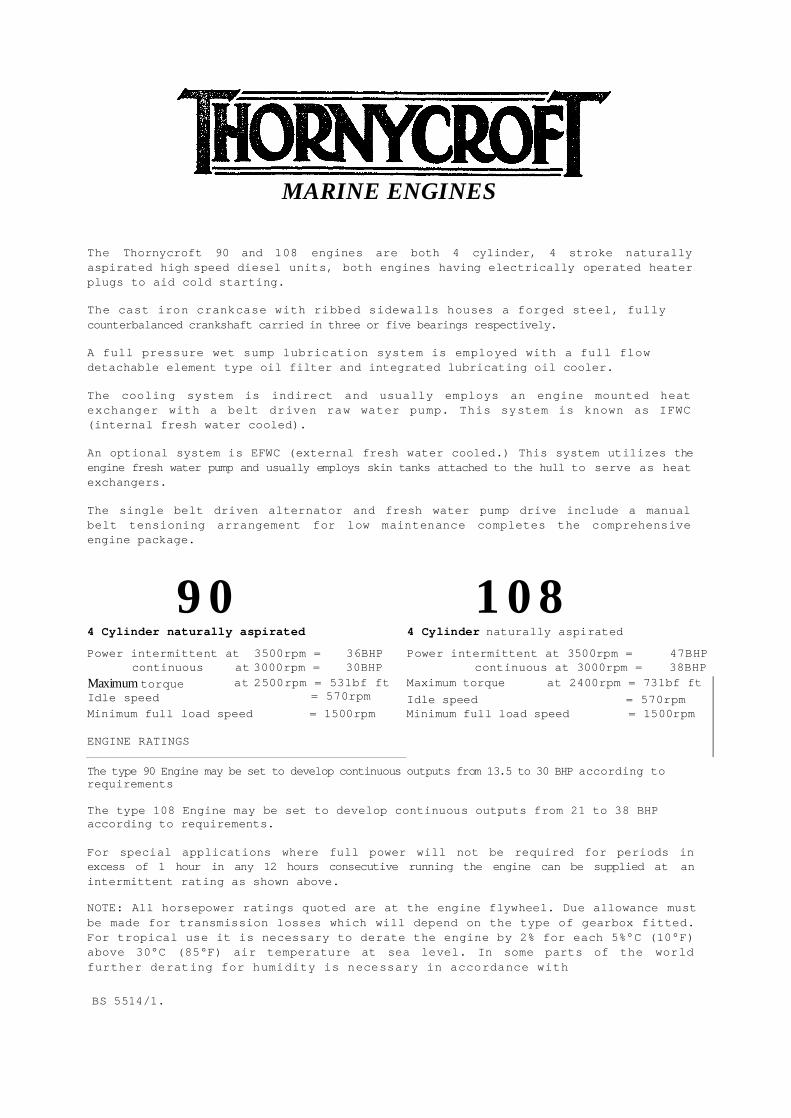
MARINE ENGINES
The Thornycroft 90 and 108 engines are both 4 cylinder, 4 stroke naturally aspirated high speed diesel units, both engines having electrically operated heater plugs to aid cold starting. The cast iron crankcase with ribbed sidewalls houses a forged steel, fully counterbalanced crankshaft carried in three or five bearings respectively. A full pressure wet sump lubrication system is employed with a full flow detachable element type oil filter and integrated lubricating oil cooler. The cooling system is indirect and usually employs an engine mounted heat exchanger with a belt driven raw water pump. This system is known as IFWC (internal fresh water cooled). An optional system is EFWC (external fresh water cooled.) This system utilizes the engine fresh water pump and usually employs skin tanks attached to the hull to serve as heat exchangers. The single belt driven alternator and fresh water pump drive include a manual belt tensioning arrangement for low maintenance completes the comprehensive engine package.
90 108 4 Cylinder naturally aspirated 4 Cylinder naturally aspirated Power intermittent at 3500rpm = 36BHP Power intermittent at 3500rpm = 47BHP
continuous at 3000rpm = 30BHP continuous at 3000rpm = 38BHP Maximum torque at 2400rpm = 731bf ft Maximum torque
Idle speed at 2500rpm = 531bf ft
= 570rpm Idle speed = 570rpm Minimum full load speed = 1500rpm
ENGINE RATINGS
Minimum full load speed = 1500rpm
The type 90 Engine may be set to develop continuous outputs from 13.5 to 30 BHP according to requirements The type 108 Engine may be set to develop continuous outputs from 21 to 38 BHP according to requirements. For special applications where full power will not be required for periods in excess of 1 hour in any 12 hours consecutive running the engine can be supplied at an intermittent rating as shown above.
NOTE: All horsepower ratings quoted are at the engine flywheel. Due allowance must be made for transmission losses which will depend on the type of gearbox fitted. For tropical use it is necessary to derate the engine by 2% for each 5%°C (10°F) above 30°C (85°F) air temperature at sea level. In some parts of the world further derating for humidity is necessary in accordance with

INITIAL STARTING OF ENGINE
PAGE _. Engine mounting and dipstick marking. Filling engine with oil. 2. Lubricant specification for engine and gearbox. Filling gearbox. 3. Coolant/Corrosion inhibitor specification. Filling cooling system. 4. Priming the engine oil system. 5. Bleeding the fuel system type 90 engines. 6. Bleeding the fuel system type 108 engines. 7. Initial start. Normal start. Running in. 8. Operating guidelines. 9. Operating guidelines.
MAINTENANCE
Maintenance schedule. Engine oil and filter change Engine oil and filter change Fuel filter change. Cleaning fuel lift pump. Gearbox oil change. Cleaning air filter. Alternator drive belt adjustment and replacement. Raw water pump adjustment and replacement. Checking and setting valve clearances. Procedure for retorquing cylinder head nuts. Removal/Refitting fuel injectors. Changing coolant. Draining raw water system. External fresh water cooled engines. Electrical system. Fault finding. Fault finding. Laying up the engine. Re-commissioning. Notes.
10. 11. 12. 13. 14. 15. 16. 17.
Type 90 engines. Type 108 engines.
18. 19 20. 21. 22. 23. 24. 25. 26. 27. 28. 29.

THORNYCROFT
Page 1 CHECKING ENGINE MOUNTING
The maximum installed angle of the engine is 15°, engine types 90/2, 108 and 108/2 (10° for engine type 90). This allows for a further rise of 4° when the craft is moving. Check the angle of installation using the centreline of the mounting feet bolts as a datum. Measure vertically on the centreline of the underside of the front mounting foot bolt to find the angle of installation Fig. 1
Fig. 1
Horizontal Line Type 90 Type 90/2 Type 108
A 93mm = 10° A 138mm = 150 A 136mm = 15° 46mm = 5° 93mm = 10° 91mm = 10°
46mm = 5° 46mm = 5° MARKING DIPSTICK, FILLING WITH OIL Your engine is despatched from the factory without engine or gearbox oil and with an unmarked engine dipstick. After the boat is launched, and is resting at its normal trim angle, remove the oil filler cap from the rocker box Fig. 2 and pour 3.9 litres for type 90, 4.5 litres for type 90/2 or 4.8 litres for type 108 of specified lubricant through the filler hole. Allow 5 minutes for .the oil to drain into the sump, withdraw the dipstick and mark it for maximum oil level Fig. 3 (Use a centre punch for marking as filing a notch can cause fatigue and eventual breakage while the engine is running). Then mark dipstick using the same method 12.7mm (%") below the maximum mark and this will be the minimum level.
CHECKING ENGINE MOUNTING, MARKING DIPSTICK, FILLING ENGINE WITH OIL


LUBRICANT ENGINE AND GEARBOX
`Page 2 ENGINE OIL
RUNNING IN OILS
Do NOT use special running-in lubricating oils for new or rebuilt engines. Use the lubricating oils specified for normal engine operation.
ENGINE OIL VISCOSITY RECOMMENDATIONS The use of a multi-graded lubricating oil has been found to improve oil consumption and improve engine cranking in cold temperatures while maintaining lubrication at high operating temperatures. A multi-grade oil conforming to MIL-L-20104B is. recommended with the viscosity grades shown in Fig. 4. The use of single grade lubricating oil is not recommended except for synthetic oils used in arctic conditions.
Atmospheric Temperature Viscosity
Above -10°C 20W50
-20°C to 10°C 1OW30 or 1OW40
Below -10°C 5W30 or 5W40
Fig. 4.
GEARBOX OIL
Borg Warner Automatic Transmission Fluid (Type A) Hurth Automatic Trnamsission Fluid (Type A) Newage PRM SAE 20 Engine Oil Minus 18°C to 0°C
SAE 30 engine Oil Above 0°C
FILLING THE GEARBOX Remove the oil filler plug combined dipstick from the top of the gearbox. This is in approximately the same position on Hurth, Newage PRM and Borg Warner. Using a plastic bottle or funnel, fill the gearbox up to the maximum mark on the dipstick. There is one level mark on the Hurth dipstick, the others have high and low marks.
THORNYCRO
FT

Fig. 5.
M Fig. 8
COOLING SYSTEM
Page 3
COOLANT Use anti-freeze during all seasons to protect the engine cooling system from corrosion as well as freeze damage. Using the following anti-freeze solution %.
25% 33% 50% Solution Solution Solution
Complete protection lO°F(-12C) 3°F(-16C) - 4°F(-20°C) Safe protection 1°F(-17C) -8°F(-22C) -18°F(-28°C)
In tropical climates where anti-freeze availability may be limited, corrosion inhibitor to protect the engine cooling system.
NOTE: Corrosion inhibitor is NOT an anti-freeze. COOLANT QUANTITIES Complete system including engine (IFWC) types 90 and 108 engines.
5.1 Litres
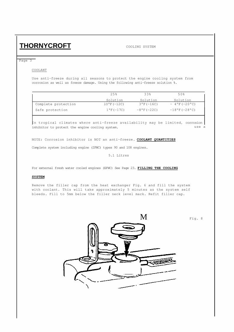
For external fresh water cooled engines (EFWC) See Page 23. FILLING THE COOLING
SYSTEM Remove the filler cap from the heat exchanger Fig. 6 and fill the system with coolant. This will take approximately 5 minutes as the system self bleeds. Fill to 5mm below the filler neck level mark. Refit filler cap.
THORNYCROFT
use a

M Fig. 9
405i l I

Page 4
PRIMING THE ENGINE OIL SYSTEM (TYPE 90/2R ENGINES ONLY)
As only a residual amount of oil is present in the oil pump, filter and oil galleries of the engine, it is therefore necessary to prime the system before the engine is run. Connect the engine starter batteries disconnect power to the fuel solenoid valve on the injection pump Fig. 7 and crank the engine over using the key starter switch until pressure registers on the oil pressure gauge. Stop cranking and check the engine and gearbox for oil or water leaks. Replace power connector.
Fig. 7
PRIMING THE ENGINE OIL SYSTEM (TYPE 90 AND/108 ENGINES) As only a residual amount of oil is present in the oil pump filter and oil galleries of the engine it is therefore necessary to prime the system before the engine is run. Connect the engine starter batteries, operate the key starter switch with the stop control out, crank the engine over until pressure registers on the oil pressure gauge. Stop cranking and check the engine and gearbox for oil or water leaks.
PRIMING THE ENGINE OIL SYSTEM THOMYCWFT

Page 5 BLEEDING THE FUEL SYSTEM
Slacken the bleed valve on the injection pump Fig. 8. Operate the lift pump Fig. 9 and when the fuel coming from the valve is free of air bubbles, tighten the valve.
Fig. 8 Slacken the unions at the injector ends of any two high pressure pipes. Fig. 10. Ensure that the stop control is in the run position and the engine speed control is in the fully open position. Crank the engine until the fuel coming from both pipes is free from air bubbles, then tighten the unions. NB. After initial start procedure has been observed start the engine and allow it to idle until it is running evenly on all four cylinders.
THORNYCROFT BLEEDING THE FUEL SYSTEM TYPE 90 ENGINES

Fig. 10
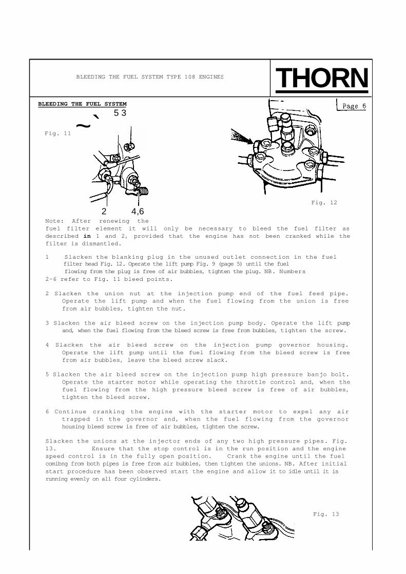
Fig. 13
BLEEDING THE FUEL SYSTEM 5 3
Fig. 11 ~`
2 4,6 Note: After renewing the fuel filter element it will only be necessary to bleed the fuel filter as described in 1 and 2, provided that the engine has not been cranked while the filter is dismantled. 1 Slacken the blanking plug in the unused outlet connection in the fuel
filter head Fig. 12. Operate the lift pump Fig. 9 (page 5) until the fuel flowing from the plug is free of air bubbles, tighten the plug. NB. Numbers
2-6 refer to Fig. 11 bleed points. 2 Slacken the union nut at the injection pump end of the fuel feed pipe.
Operate the lift pump and when the fuel flowing from the union is free from air bubbles, tighten the nut.
3 Slacken the air bleed screw on the injection pump body. Operate the lift pump
and, when the fuel flowing from the bleed screw is free from bubbles, tighten the screw. 4 Slacken the air bleed screw on the injection pump governor housing.
Operate the lift pump until the fuel flowing from the bleed screw is free from air bubbles, leave the bleed screw slack.
5 Slacken the air bleed screw on the injection pump high pressure banjo bolt.
Operate the starter motor while operating the throttle control and, when the fuel flowing from the high pressure bleed screw is free of air bubbles, tighten the bleed screw.
6 Continue cranking the engine with the starter motor to expel any air
trapped in the governor and, when the fuel flowing from the governor housing bleed screw is free of air bubbles, tighten the screw.
Slacken the unions at the injector ends of any two high pressure pipes. Fig. 13. Ensure that the stop control is in the run position and the engine speed control is in the fully open position. Crank the engine until the fuel comibng from both pipes is free from air bubbles, then tighten the unions. NB. After initial start procedure has been observed start the engine and allow it to idle until it is running evenly on all four cylinders.
BLEEDING THE FUEL SYSTEM TYPE 108 ENGINES THORNYCROF
Fig. 12

THORNYCROFT Page 7
INITIAL START
With all systems filled, primed and checked the engine may be started. Run it for 2 to 3 minutes then stop it. Top up engine, gearbox oil and water levels to the high mark. The engine and gearbox are now ready for use. Oil pressure should be observed within 15 seconds.
NORMAL STARTING PROCEDURE 1 Put gearbox selector lever in neutral.
2 Ensure the stop control is fully disengaged.
3 Set the engine speed control lever fully open. 4 Turn the key to 'H' position on starter switch and hold for 30 seconds (this
preheats the heater plugs). (This is not necessary for a warm engine. Also control level only needs to be set half open).
5 Turn the key to 'H & S' position and the starter motor will crank up the engine. CAUTION: If the starter fails to crank up the engine within 10 seconds, release the switch key and wait for the starter motor to come to a complete stop. Then turn the key to 'H & S' position again. Do not engage the starter motor for more than 30 seconds, then wait 2 minutes between unsuccessful attempts.
6 Move the throttle position to idle as soon as engine starts.
7 Oil pressure should be observed within 15 seconds. 8 To stop the engine, pull the stop control. RUNNING IN
The care given to an engine in the first 20 hours of operation will result in longer life, better performance and more economical operation. During this period follow these recommendations. 1 Warm up the engine before placing it under load.
2 Do not operate the engine at idle or full load for more than 5 minutes. 3 Avoid
constant speed.
4 Observe oil pressure and temperature gauges. 5 Check the oil and coolant levels frequently. GENERAL PRECAUTIONS
1 NEVER attempt to start the engine with the gearbox control lever in any
position other than neutral.
2 NEVER stop the engine without first engaging neutral.
3 When changing the control lever from ahead to astern or vice versa pause in neutral.
INITIAL START, NORMAL START, RUNNING IN

I Page 8
COMPLIANCE WITH THE FOLLOWING RECOMMENDATIONS CAN RESULT IN LONGER LIFE, BETTER PERFORMANCE AND MORE ECONOMICAL OPERATION OF YOUR ENGINE. Routinely perform all of the specified maintenance, including the "First Start of the Day" checks.
Use anti-freeze during all seasons to protect the cooling system from corrosion as well as freeze damage. Never operate the engine without a thermostat.
Use quality fuel that is free of water and other contaminants. Monitor the oil
pressure and temperature indicators frequently. AVOID FULL THROTTLE
OPERATION WHEN THE ENGINE IS COLD. When starting a cold engine, bring the engine up to operating speed slowly to allow the oil pressure to stabilise as the engine warms up. If temperatures are below 0°C (32°F), operate the engine at moderate speeds for 5 minutes before full loads are applied. AVOID IDLING THE ENGINE FOR MORE THAN 10 MINUTES Long periods of idling may be harmful to your engine because combustion chamber temperatures can drop so low that the fuel may not burn completely. Carbon can then form which may clog the injector spray holes and also cause valves and piston rings to stick. AVOID OVERHEATING THE ENGINE Coolant temperature must not exceed 99°C (210°F) with a 70 kPa (10 psi) expansion tank cap AND A MINIMUM OF 50% mixture of ethylene-glycol and water. IDLE THE ENGINE A FEW MINUTES BEFORE ROUTINE SHUTDOWN After full load operation, idle the engine 3 to 5 minutes before shutting it off to allow the lubricating oil and coolant to carry heat away from the combustion chamber, bearings, shafts, etc. AVOID LOW COOLANT TEMPERATURE OPERATION Continual operation at low coolant temperature below 60°C (150°F) can be
harmful to the engine. Low coolant temperature can cause incomplete combustion allowing carbon and varnish to form that can damage piston rings and injectornozzles. Also, the unburnt fuel can enter the crankcase diluting thelubricating oil causing rapid wear to other moving parts.
OPERATING GUIDELINES THORNYCROFT

Page 9
DO NOT OPERATE THE ENGINE WITH LOW OIL PRESSURE
When the engine is at normal operating temperature, the minimum oil pressures required are:
Idle (570 RPM) ........................... 1 bar (15 psi) Full Speed and Load .................... 2.3 bar (35 psi)
DO NOT OPERATE THE ENGINE WITH FAILED PARTS
Practically all failures give some warning before the parts fail. Be on the alert for changes in performance, sounds and visual tip-offs that indicate either service or repair is needed. Some important clues are:
Engine misfiring or vibrating severely Sudden loss of power Unusual engine noises Fuel, oil or coolant leaks Sudden change in the engine operating temperature Excessive smoke Loss of oil pressure
SAFETY PRECAUTIONS
Safety is built into every engine; however, like any other mechanical device, it can present serious threat to life and limb if imprudently operated and maintained. Remember that the best safeguards against accidents are to keep ever mindful of the potential dangers and to always use good common sense.
THORNYCROFT OPERATING GUIDELINES
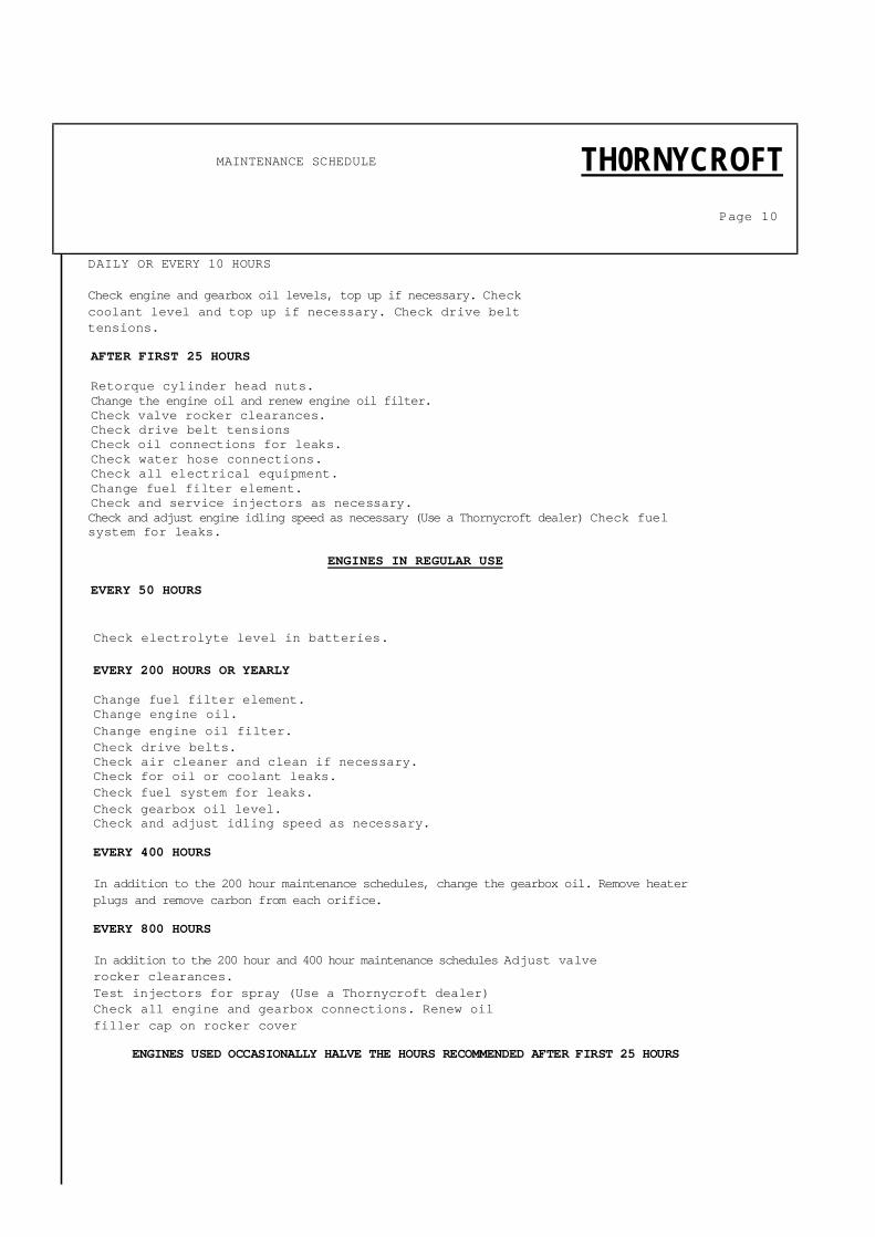
DAILY OR EVERY 10 HOURS Check engine and gearbox oil levels, top up if necessary. Check coolant level and top up if necessary. Check drive belt tensions. AFTER FIRST 25 HOURS Retorque cylinder head nuts. Change the engine oil and renew engine oil filter. Check valve rocker clearances. Check drive belt tensions Check oil connections for leaks. Check water hose connections. Check all electrical equipment. Change fuel filter element. Check and service injectors as necessary. Check and adjust engine idling speed as necessary (Use a Thornycroft dealer) Check fuel system for leaks.
ENGINES IN REGULAR USE EVERY 50 HOURS
Check electrolyte level in batteries.
EVERY 200 HOURS OR YEARLY Change fuel filter element. Change engine oil. Change engine oil filter. Check drive belts. Check air cleaner and clean if necessary. Check for oil or coolant leaks. Check fuel system for leaks. Check gearbox oil level. Check and adjust idling speed as necessary. EVERY 400 HOURS In addition to the 200 hour maintenance schedules, change the gearbox oil. Remove heater plugs and remove carbon from each orifice. EVERY 800 HOURS In addition to the 200 hour and 400 hour maintenance schedules Adjust valve rocker clearances. Test injectors for spray (Use a Thornycroft dealer) Check all engine and gearbox connections. Renew oil filler cap on rocker cover
ENGINES USED OCCASIONALLY HALVE THE HOURS RECOMMENDED AFTER FIRST 25 HOURS
MAINTENANCE SCHEDULE TH0RNYCROFT
Page 10

THORNYCROFT Page 11
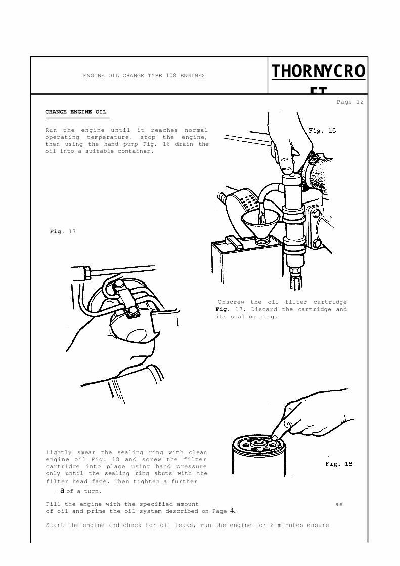
CHANGE ENGINE OIL
Run the engine until it reaches normal operating temperature, stop the engine, then using the hand pump Fig. 14 drain the oil into a suitable container.
Fig. 14
CHANGE ENGINE OIL FILTER
Slacken the centre fixing bolt '1' Fig. 15 and withdraw the filter bowl '2' and filter element '3' together. Discard the filter element and
ENGINE OIL CHANGE TYPE 90 ENGINES

sealing ring '4'.
Replace with new element and sealing ring, ensuring that the ring is correctly seated in the filter head '5' and tighten the centre bolt.
Fill the engine with the specified amount of oil and prime the oil system as described on Page 4. Start the engine and check for oil leaks, run the engine for 2 minutes ensure pressure registers on the gauge. Stop the engine and allow a few minutes for oil to settle. Check oil level, top up if necessary.
Fig. 15
Page 12 CHANGE ENGINE OIL
Run the engine until it reaches normal operating temperature, stop the engine, then using the hand pump Fig. 16 drain the oil into a suitable container.
Fig. 17
Unscrew the oil filter cartridge Fig. 17. Discard the cartridge and its sealing ring.
Lightly smear the sealing ring with clean engine oil Fig. 18 and screw the filter cartridge into place using hand pressure only until the sealing ring abuts with the filter head face. Then tighten a further - a of a turn.
Fill the engine with the specified amount of oil and prime the oil system described on Page 4. Start the engine and check for oil leaks, run the engine for 2 minutes ensure
ENGINE OIL CHANGE TYPE 108 ENGINES THORNYCROFT
as

pressure register on the gauge. Stop the engine and allow a few minutes for Oil to settle, Check oil level and top op if necessary

THORNYCROFT
Page 13
RENEW FUEL FILTER ELEMENT
Turn off the fuel supply tap then support the filter base '1' Fig. 19 and unscrew the centre bolt '2'. Detach the base and twist the element '3' to separate it from the filter head '4'. Remove the three sealing rings '5' from the head and base. Discard element and sealing rings. Clean base and head and assemble the filter using a new element and sealing rings. Fit the element with its strengthened rim uppermost. 'Turn on the fuel supply tap then bleed the air from the system as described on Page 5 or 6.
FUEL FILTER CHANGE

Fig. 19
Page 14
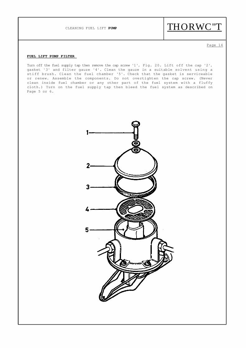
FUEL LIFT PUMP FILTER
Turn off the fuel supply tap then remove the cap screw '1', Fig. 20. Lift off the cap '2', gasket '3' and filter gauze '4'. Clean the gauze in a suitable solvent using a stiff brush. Clean the fuel chamber '5'. Check that the gasket is serviceable or renew. Assemble the components. Do not overtighten the cap screw. (Never clean inside fuel chamber or any other part of the fuel system with a fluffy cloth.) Turn on the fuel supply tap then bleed the fuel system as described on Page 5 or 6.
CLEANING FUEL LIFT PUMP THORWC"T

Fig. 20

Fig. 26
Page 15
CHANGING THE GEARBOX OIL
The gearbox oil must be changed when the gearbox has reached operating temperature. (After about 1/2 hour driving the craft).
To help the oil drain easily from the gearbox first remove the oil filler dipstick plug from the top of the gearbox. Place a suitable container under the gearbox and remove the drain plug from the underside of the gearbox and allow the oil to drain completely Fig. 21. The drain plug is in approximately the same position on the underside of Hurth, Borg Warner and Newage PRM gearboxes.
Refit the drain plug. Fill the gearbox to the maximum mark on the dipstick. Refit the filler plug, start the engine in neutral, and run the engine for 1 minute to allow the oil to circulate. Stop the engine and check the oil level. Top up if necessary to the maximum mark on the dipstick.
THORNYCROFT GEARBOX OIL CHANGE

Fig. 27
Illustration shows PRM 160 gearbox

CLEANING AIR FILTER
Page 16
CLEANING AIR FILTER
Slacken the clip on the breather pipe and pull the pipe off the air cleaner then, slacken the screw Fig. 22 this allows removal of the outer casing and the air filter gauze. Submerge the casing and gauze in a bath of clean paraffin or diesel fuel, agitate them vigorously to remove dirt particles. Shake the filter dry by hand or blow dry with compressed air, then refit.
Fig. 22
THORNYCROFT
CAUTION: WHEN USING A COMPRESSED AIR LINE GREAT CARE MUST BE OBSERVED AND
GOGGLES MUST BE WORN

Page 17
SAFETY: BEFORE ATTEMPTING THESE OPERATIONS
DISCONNECT THE STARTER BATTERIES Adjusting
Alternator Drive Belt
Type 90 alternator is shown in the illustration Fig. 23 but procedure for adjusting the alternator drive belt is the same for type 108 engines. Slacken the nuts and bolts 1-4. Move alternator away from the engine until the deflection of the belt (arrowed) is 19mm (0.75 in) when pressed using finger pressure only at the longest point between pulleys. Excessive tension will cause early wear of the belt, water pump bearing and alternator bearing. While a slack belt will slip, causing overheating of the engine and insufficient charging of the batteries. Check deflection after retightening. Replacing Alternator Drive Belt Slacken the nuts and bolts (Fig. 23) 1-4, move alternator in towards engine. Remove old belt from pulleys and replace with new drive belt. Retighten nuts and bolts. Following the instructions above readjust the drive belt tension.
Fig. 23
Adjusting Raw Water Pump Drive Belt
Slacken the nuts and bolts (Fig. 24) 1 and 2 and retension the belt as described above for the alternator. (The deflection of the belt must be 10-12mm 0.39-0.47in). Check deflection after retightening.
Replacing Raw Water Pump Drive Belt
Slacken the nuts and bolts (Fig. 24) 1 and 2. Move pump in towards engine. Remove old belt from pulleys and replace with new drive belt. Retighten nuts and bolts, following the instructions above readjust the drive belt tension.
Fig. 24
THORNYCROFT DRIVE BELT ADJUSTMENT AND REPLACEMENT ALTERNATOR AND RAW WATER PUMP
Page 18
SAFETY: BEFORE ATTEMPTING THIS OPERATION DISCONNECT THE STARTER BATTERIES
Setting Valve Clearances Engine Cold
Slacken the rocker cover bolts and remove rocker cover. Discard the gasket. Turn
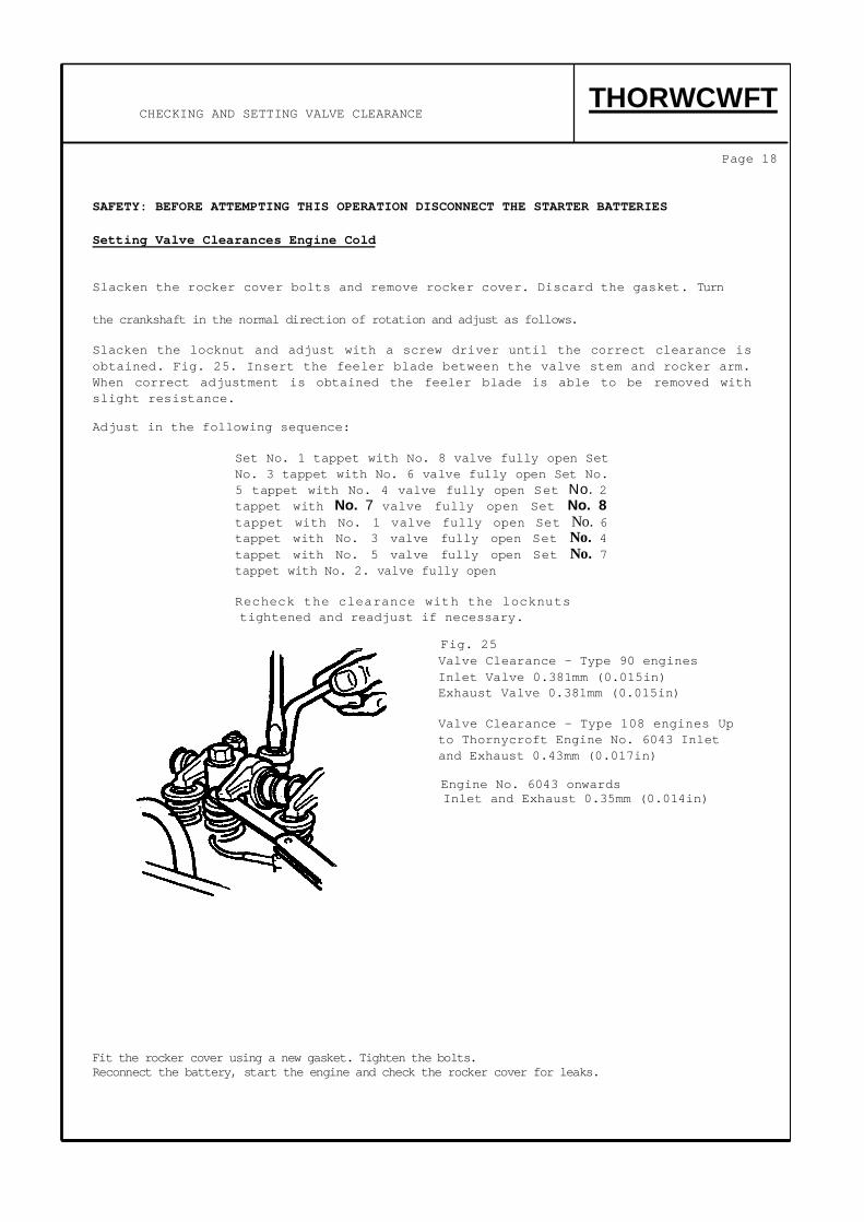
the crankshaft in the normal direction of rotation and adjust as follows. Slacken the locknut and adjust with a screw driver until the correct clearance is obtained. Fig. 25. Insert the feeler blade between the valve stem and rocker arm. When correct adjustment is obtained the feeler blade is able to be removed with slight resistance. Adjust in the following sequence:
Set No. 1 tappet with No. 8 valve fully open Set No. 3 tappet with No. 6 valve fully open Set No. 5 tappet with No. 4 valve fully open Set No. 2 tappet with No. 7 valve fully open Set No. 8 tappet with No. 1 valve fully open Set No. 6 tappet with No. 3 valve fully open Set No. 4 tappet with No. 5 valve fully open Set No. 7 tappet with No. 2. valve fully open
Recheck the clearance with the locknuts tightened and readjust if necessary.
Fig. 25 Valve Clearance - Type 90 engines Inlet Valve 0.381mm (0.015in) Exhaust Valve 0.381mm (0.015in)
Valve Clearance - Type 108 engines Up to Thornycroft Engine No. 6043 Inlet and Exhaust 0.43mm (0.017in)
Engine No. 6043 onwards Inlet and Exhaust 0.35mm (0.014in)
Fit the rocker cover using a new gasket. Tighten the bolts. Reconnect the battery, start the engine and check the rocker cover for leaks.
CHECKING AND SETTING VALVE CLEARANCE THORWCWFT

Page 19 1 PROCEDURE FOR NEW ENGINES WHICH HAVE RUN FOR 25 HOURS
A Run engine and stop when normal operating temperature is reached.
B Slacken the cylinder head nuts by approximately 1/6" of a turn (one flat of the nut) following the sequence shown using service tool 18G 1457 to reach the nuts in the centre row.
Fig. 26
I C Tighten the nuts in the sequence shown to 10.4 kgf m (75 lb ft).
THORNYCROFT PROCEDURE FOR RETORQUING CYLINDER HEAD NUTS
11 6 5 12
00 00 0o ? 1 90 090 1 0 A OQ
14 107 3 1 4 89 13

Slacken the valve rocker pedestal nuts by 1/6" of a turn (one flat of the nut) and retorque to 3.5 kgf m (25 lb ft). Adjust valve rocker clearances (Page 18).
2 PROCEDURE WHERE PART ENGINES HAVE BEEN FITTED OR WHERE CYLINDER HEADS ARE REMOVED OR REPLACED DURING REPAIR OPERATIONS
A The cylinder head nuts should not be more than finger tight until the rocker shaft assembly has been fitted.
B Tighten the nuts to 10.4 kgf m (75 lb ft) type 108 engines, 9.8 kgf m
C
D
When the
(.71 lb ft) type 90 engines in the sequence shown in procedure Using service tool 18G1457 to reach centre row. Fig. 27.
Tighten the valve rocker pedestal nuts to 3.5 kgf m (25 lb ft).
Adjust the valve rocker clearance as in procedure 1.
engine has run for Y2 hour carry out the operation described
1.
in
procedure 1.
Fig. 27

THORNYCROFT
Page 20 REMOVING FUEL INJECTORS Injector cleaning and spray testing can only be carried out with specialised equipment, therefore this must be done by a Distributor or Dealer. Fig. 28. Disconnect the feed pipe '1' and spill rail '2'. Note the sealing washers '3' on each side of the spill rail banjo union. Remove the injector securing bolts '4' and withdraw the injector. Fit protective caps to all open connections.
Fig. 28
REFITTING FUEL INJECTORS
Remove protective caps. Ensure the washers are fitted to the injectors as shown in Fig. 29. It is most important to tighten the injector fixings evenly and to the correct torque of 1.65 kgf m (12 lbf ft), overtightening or uneven tightening of the injector can distort the nozzle and will usually cause a misfire to occur when normal running temperature is reached. Reconnect the injector pipes, do not overtighten the unions.
TO REMOVE HEATER PLUGS AND CLEAN ORIFICES. Disconnect the battery. Remove electrical leads '1' Fig.29A and unscrew each plug '2' from the cylinder head. Insert a twist drill of 4.37mm (11/64in)dia. '3' into the threaded holes in the head '4'. Turn the drill, by hand, to remove carbon build-up. Remove the drill and clean any particles of carbon from conical seatings in the cylinder head. Refit the heater plugs and electrical leads. Reconnect the
REMOVAL AND REFITTING FUEL INJECTORS
Fig. 29

battery.
Fig.29A

CHANGING COOLANT
Page 21
CHANGING COOLANT
Remove filler cap from heat exchanger, place a suitable container beneath the drain plug Fig. 30. Remove plug and allow to drain. Place suitable container beneath drain tap in cylinder block Fig. 31. Remove tap and allow to drain.
Replace both plug and tap then refill with coolant of the correct strength for conditions
TAT

to be encountered. See Page. 3.
Fig. 30
i

Fig. 31

DRAINING RAW WATER SYSTEM
Page 22 DRAIN THE RAW WATER SYSTEM Slacken the six screws Fig.32 on the raw water pump. Remove end covers from heat exchanger and drain tubes either by removing the tube stack or by blowing out with compressed air. Remove oil cooler and drain tubes or blow out with compressed air. Alternatively disconnect raw water pipework before gearbox oil cooler and pipe from oil cooler into a container of anti-freeze mixture and flush through system returning anti-freeze mixture from water injection bend back into container, this ensuring that any water pockets contain anti-freeze.
NOTE: ANTI-FREEZE MIXTURE MUST BE OF CORRECT STRENGTH FOR CONDITIONS TO BE ENCOUNTERED.
Fig. 32
CAUTION: WHEN USING A COMPRESSED AIR LINE GREAT
CARE MUST BE OBSERVED AND GOGGLES MUST BE WORN.

ROUTINE MAINTENANCE OF RAW WATER SYSTEM IFWC
THESE NOTES DO NOT APPLY TO EXTERNAL FRESH WATER COOLED ENGINES Examine and clean the sea inlet strainer at regular intervals. Do Not remove the strainer when the engine is running as foreign matter can be drawn into the system and cause irreparable damage to the pump. The sea cock must be FULLY OPEN when the engine is running. If the sea cock is partially closed, air can be drawn in with consequential failure of the raw water pump and engine overheating. Check the raw water discharge pipe immediately after starting the engine to see if the raw water pump is functioning.
The engine MUST NOT run without a flow of raw water through the heat exchanger. RAW WATER PUMP, the raw water pump is self priming and fitted with a neoprene impellor. It depends on the raw water for its lubrication. DO NOT run dry. More than 30 seconds running without water will burn the impellor and be contributory to an early failure. When replacing the end cover gasket, it is essential to use the correct part; variation of the gasket thickness can cause loss of'self priming ability or seizure.

Page 23
This consists of a closed circuit fresh water system with a fresh water circulator, combined header tank and exhaust manifold, dry exhaust outlet and water/coolant tanks normally fitted to the skin of the craft. It is therefore important when filling this system with anti-freeze solution or corrosion inhibitor that the total capacity of the tanks, associated pipework and the engine cooling system is taken into consideration. Your boat builder will advise you on these figures.
We have included the box below for you to fill in these figures for your craft.
THORNYCROFT EXTERNAL FRESH WATER COOLED ENGINES ONLY (EFWC)
Name of Craft External Fresh Water Cooled System Capacity Date Change Due

ELECTRICAL SYSTEM
Page 24
Electrical System
An insulated return system is employed on the type 90 and 108 engines. The 12 volt alternator has a built-in voltage regulator which automatically adjusts the charging rate to provide sufficient electric current to keep the battery fully charged under normal operating conditions. The alternator requires no lubrication maintenance. Do NOT disconnect the battery leads while the engine is running. Ensure that the correct battery terminal is connected to a good earth on the starter A coating of a good grade of petroleum jelly will protect the terminals from corrosion.
The electrolyte level should be 6 to 9mm (0.25 to 0.38in) above the top of the plates. If the electrolyte is below the correct level, add the required amount of distilled water. Distilled water for battery use should be kept in clean, covered, non-corrodible vessels. In cold weather, add water only immediately before running the engine, so that the charging will mix the water and electrolyte and prevent freezing. If the battery is allowed to stand at low temperatures in a partially discharged condition there is a possibility that it may freeze, causing damage to the container. Take care therefore, to keep the battery as fully charged as possible. The specific gravity of the electrolyte when the battery is fully charged should be 1,275 at a temperature of 25°C (77°F). At differing temperatures the specific gravity of a fully charged battery will change. The specific gravity of any given temperature can be calculated by subtracting 0.004 from 1,275 for every 6°C change above 25°C and adding 0.004 to 1,275 for every 6°C below 25°C. Keep the battery filler plugs and connections tight and the top of the battery clean. Wiping the battery with a rag moistened with ammonia will counteract the effect of any of the solution which may be on the outside of the battery. Wear protective goggles when carrying out this operation. If ammonia is accidentally splashed in the eyes, wash out thoroughly at once with clean water and SEEK QUALIFIED MEDICAL ADVICE IMMEDIATELY. Using 'Jumper' Cables
To avoid the possibility of extensive damage to your charging system it is important to observe the following points when using battery 'jumper' cables to start an engine having a discharged battery. The positive (+) terminals of the batteries must be connected through one cable (usually red), and the negative (-) terminals connected through the other cable. If this procedure is not followed, extensive damage may be done to the charging system.
CAUTION: Since explosive hydrogen gas is always present, sparks or flames should not be allowed near the battery. When using 'jumper' cables, the cables should always be attached to the booster battery first.
THORNYCROFT

Page 25
FAULT FINDING
ENGINE WILL NOT START
Starter does not ELECTRICAL FAULT crank engine Battery run down
Lead disconnected Faulty starter switch Faulty starter motor
Starter cranks ELECTRICAL FAULT engine slowly Battery partly run down
Terminal(s) loose Connections dirty Faulty starter motor
MECHANICAL FAULT Wrong grade engine oil
Starter cranks ELECTRICAL FAULT engine normally Faulty glow plugs
Faulty wiring connection
MECHANICAL FAULT Injection timing incorrect Poor cylinder compression Blocked air intake
FUEL FAULT Fuel Not Reaching Injection Pump Insufficient fuel in tank
Blocked fuel pipeline Blocked fuel tank vent Restricted fuel filter Air leaks in pipeline
Fuel Reaching Injection Pump Air in fuel system
Faulty injectors
THORNYCROFT FAULT FINDING