THM 4L80-E - Центр...
120
INDEX Copyright © ATSG 1991 THM 4L80-E AUTOMATIC TRANSMISSION SERVICE GROUP 18639 SW 107TH AVENUE MIAMI, FLORIDA 33157 (305) 670-4161 2 POWERFLOW CHART AND SHIFT SOLENOID PATTERN ..................................................... 4 SHIFT SPEED CHART ....................................................................................................................... 5 LINE PRESSURE TESTS .................................................................................................................... 6 TROUBLE SHOOTING CHARTS ..................................................................................................... 7 OIL PASSAGE IDENTIFICATION .................................................................................................... 27 CHECK BALL LOCATIONS .............................................................................................................. 34 1991-92 WIRING SCHEMATIC ......................................................................................................... 35 TRANSMISSION DISASSEMBLY ..................................................................................................... 36 TRANSMISSION ASSEMBLY PROCESS ........................................................................................ 45 THRUST BEARING LOCATIONS .................................................................................................... 91 TROUBLE CODE DESCRIPTION ................................................................................................... 92 TORQUE SPECIFICATIONS ............................................................................................................ 94 UPDATED WIRE HARNESS AND CASE CONNECTOR FOR 1993 .......................................... 95 UPDATED ELECTRONICS FOR 1994 ............................................................................................. 99 UPDATED CENTER LUBE SYSTEM FOR 1997 ............................................................................ 104 UPDATED MANUAL 2ND BAND FOR 1999 ................................................................................... 113 UPDATED OVERRUN CLUTCH FOR 2001 ................................................................................... 116
Transcript of THM 4L80-E - Центр...

INDEX
Copyright © ATSG 1991
THM 4L80-E
AUTOMATIC TRANSMISSION SERVICE GROUP18639 SW 107TH AVENUEMIAMI, FLORIDA 33157
(305) 670-4161
2
POWERFLOW CHART AND SHIFT SOLENOID PATTERN ..................................................... 4
SHIFT SPEED CHART ....................................................................................................................... 5
LINE PRESSURE TESTS .................................................................................................................... 6
TROUBLE SHOOTING CHARTS ..................................................................................................... 7
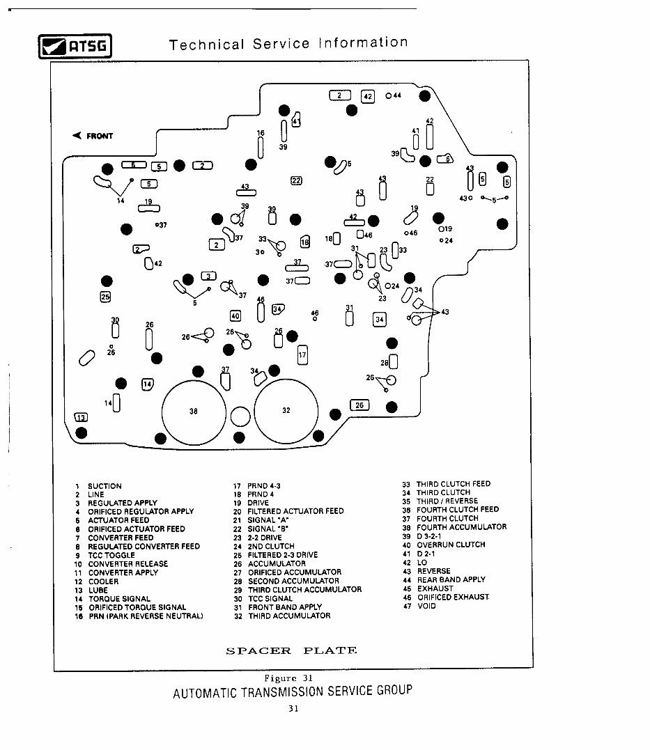
OIL PASSAGE IDENTIFICATION .................................................................................................... 27
CHECK BALL LOCATIONS .............................................................................................................. 34
1991-92 WIRING SCHEMATIC ......................................................................................................... 35
TRANSMISSION DISASSEMBLY ..................................................................................................... 36
TRANSMISSION ASSEMBLY PROCESS ........................................................................................ 45
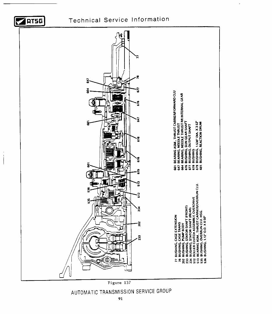
THRUST BEARING LOCATIONS .................................................................................................... 91
TROUBLE CODE DESCRIPTION ................................................................................................... 92
TORQUE SPECIFICATIONS ............................................................................................................ 94
UPDATED WIRE HARNESS AND CASE CONNECTOR FOR 1993 .......................................... 95
UPDATED ELECTRONICS FOR 1994 ............................................................................................. 99
UPDATED CENTER LUBE SYSTEM FOR 1997 ............................................................................ 104
UPDATED MANUAL 2ND BAND FOR 1999 ................................................................................... 113
UPDATED OVERRUN CLUTCH FOR 2001 ................................................................................... 116
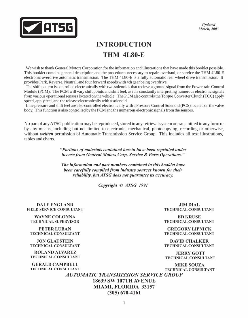
INTRODUCTION
THM 4L80-E
AUTOMATIC TRANSMISSION SERVICE GROUP18639 SW 107TH AVENUEMIAMI, FLORIDA 33157
(305) 670-4161
DALE ENGLANDFIELD SERVICE CONSULTANT
ED KRUSETECHNICAL CONSULTANT
WAYNE COLONNATECHNICAL SUPERVISOR
PETER LUBANTECHNICAL CONSULTANT
JIM DIALTECHNICAL CONSULTANT
GREGORY LIPNICKTECHNICAL CONSULTANT
JERRY GOTTTECHNICAL CONSULTANT
JON GLATSTEINTECHNICAL CONSULTANT
DAVID CHALKERTECHNICAL CONSULTANT
MIKE SOUZATECHNICAL CONSULTANT
ROLAND ALVAREZTECHNICAL CONSULTANT
GERALD CAMPBELLTECHNICAL CONSULTANT
No part of any ATSG publication may be reproduced, stored in any retrieval system or transmitted in any form or by any means, including but not limited to electronic, mechanical, photocopying, recording or otherwise, without written permission of Automatic Transmission Service Group. This includes all text illustrations, tables and charts.
"Portions of materials contained herein have been reprinted underlicense from General Motors Corp, Service & Parts Operations."
The information and part numbers contained in this booklet havebeen carefully compiled from industry sources known for their
reliability, but ATSG does not guarantee its accuracy.
Copyright © ATSG 1991
UpdatedMarch, 2003
We wish to thank General Motors Corporation for the information and illustrations that have made this booklet possible. This booklet contains general description and the procedures necessary to repair, overhaul, or service the THM 4L80-E electronic overdrive automatic transmission. The THM 4L80-E is a fully automatic rear wheel drive transmission. It provides Park, Reverse, Neutral, and four forward speeds with 4th gear being overdrive. The shift pattern is controlled electronically with two solenoids that recieve a ground signal from the Powertrain Control Module (PCM). The PCM will vary shift points and shift feel, as it is constantly interpreting numerous electronic signals from various operational sensors located on the vehicle. The PCM also controls the Torque Converter Clutch (TCC) apply speed, apply feel, and the release electronically with a solenoid. Line pressure and shift feel are also controlled electronically with a Pressure Control Solenoid (PCS) located on the valve body. This function is also controlled by the PCM and the numerous electronic signals from the sensors.
1


THM 4L80-ECENTER GEAR BOX CHANGES
FOR 1999 MODELS
CHANGE:
REASON:
PARTS AFFECTED:
INTERCHANGEABILITY:
SERVICE INFORMATION:
(4)
(2)
(1)
(3)
Beginning at the start of production for all 1999 model THM 4L80E transmissions, the planetary pinions on both carriers were produced 10% thicker than the previous models, as shown in Figure 1. This engineering change required the addition of a .041" shim in the gear train to re-center the sun gear in the new planetary pinions and affected several internal parts, that may create some confusion, and thus some mis-assembly concerns.
Increased durability and reliability.
SUN GEAR SHAFT - Required that .041" be removed from the bottom of the rear bushing journal, to accommodate the re-centering of the sun gear in the revised planetary pinion gears, as shown in Figure 4. Notice that revised sun gear shaft can be identified with a groove cut into the shaft splines, as shown in Figure 4.
ADDED .041" SHIM - There was a .041" shim added between the thrust bearing and the rear internal ring gear, to re-center the sun gear in the revised planetary pinion gears, as shown in Figure 2.
PLANETARY PINION GEARS - Were increased in length by approximately .075" in both front and rear carriers, as shown in Figure 1, for increased durability.
CENTER SUPPORT - Required a .041" recess to be machined into the center support bearing surface, to accommodate the sun gear being re-centered in the revised planetary pinion gears, as shown in Figure 3.
None of the parts listed above will interchange with any of the previous design level parts, and none of the previous design level parts can be used in the 1999 and later units.However, when all pieces listed above are used as a service package, they can be used to back service "Center Lube" model 4L80-E transmissions.The Sun Gear, Main Shaft, Rear Internal Ring Gear and all Thrust Bearings remained the same, as shown in Figures 5, 6, and 7.
SPECIAL NOTE: Some mis-assembly examples are illustrated in Figure 8 with some dimensional checks to prevent this from happening to you.
Reaction (Front) Carrier Assembly (99 Design Level) ................................................ 24202051Output (Rear) Carrier Assembly (99 Design Level) .................................................... 24202052Washer, .041" (99 Design Level) ................................................................................. 24211821Center Support Assembly (99 Design Level) .............................................................. 24217454Sun Gear Shaft Assembly (99 Design Level) .............................................................. 24207264
AUTOMATIC TRANSMISSION SERVICE GROUP
Technical Service Information
Copyright © 2003 ATSG
104

Increased In LengthBy 10% And Shim
Added To Re-CenterSun Gear
Figure 1
AUTOMATIC TRANSMISSION SERVICE GROUP
Technical Service Information
Copyright © 2003 ATSG
105

OEM PART NO.8623921
OEM PART NO.24208848
OEM PART NO.24211821
OEM PART NO.24208848
1991-1996 MODELS
1997-1998 MODELS
1999-UP MODELS
.041" ShimAdded In 1999
Figure 2
AUTOMATIC TRANSMISSION SERVICE GROUP
Technical Service Information
Copyright © 2003 ATSG
106
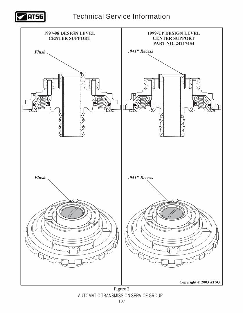
Figure 3
1999-UP DESIGN LEVELCENTER SUPPORTPART NO. 24217454
1997-98 DESIGN LEVELCENTER SUPPORT
.041" Recess
.041" Recess
Flush
Flush
*
**
*
**
AUTOMATIC TRANSMISSION SERVICE GROUP
Technical Service Information
Copyright © 2003 ATSG
107

Figure 4
1ST DESIGN LEVELSUN GEAR SHAFT
1991-96
2ND DESIGN LEVELSUN GEAR SHAFT
1997-98PART NO. 24207247
3RD DESIGN LEVELSUN GEAR SHAFT
1999- UPPART NO. 24207264
ShortenedBushing Journal
BushingJournal.041"
ShorterThis End
I.D.Groove
LongBushing Journal
AUTOMATIC TRANSMISSION SERVICE GROUP
Technical Service Information
Copyright © 2003 ATSG
108

Figure 5
PREVIOUS DESIGN LEVELSUN GEAR
1997-UP DESIGN LEVELSUN GEAR
Smaller Hole Here
DeeperGrooves
AUTOMATIC TRANSMISSION SERVICE GROUP
Technical Service Information
Copyright © 2003 ATSG
109
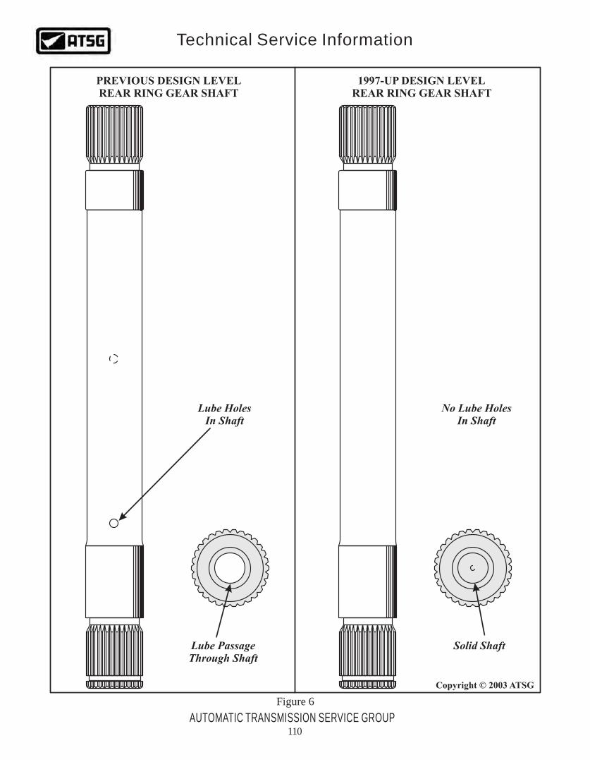
Figure 6
PREVIOUS DESIGN LEVELREAR RING GEAR SHAFT
1997-UP DESIGN LEVELREAR RING GEAR SHAFT
Lube HolesIn Shaft
Lube PassageThrough Shaft
Solid Shaft
No Lube HolesIn Shaft
AUTOMATIC TRANSMISSION SERVICE GROUP
Technical Service Information
Copyright © 2003 ATSG
110

Figure 7
PREVIOUS DESIGN LEVELREAR RING GEAR AND BEARING RACE
1997-UP DESIGN LEVELREAR RING GEAR AND BEARING RACE
No Lube PassagesThrough Splines
Four Lube PassagesThrough Splines
Round Hole InCenter Of TheBearing Race
Lube Passages InCenter Of TheBearing Race
.041" Shim AddedIn 1999 Models
AUTOMATIC TRANSMISSION SERVICE GROUP
Technical Service Information
Copyright © 2003 ATSG
111

1999 SUN GEAR SHAFTWITH 1997-98 CENTER SUPPORT
AND NO .041" SHIM
1997-98 SUN GEAR SHAFTWITH 1999 CENTER SUPPORT
AND WITH .041" SHIM
"CORRECT ASSEMBLY"WITH PROPER
SUN GEAR SHAFTAND CENTER SUPPORT
Shaft JournalApproximately
Flush With Support
Shaft JournalApproximately
.090" Above Support
Shaft JournalApproximately
.050" Above Support
Figure 8
AUTOMATIC TRANSMISSION SERVICE GROUP
Technical Service Information
Copyright © 2003 ATSG
112

THM 4L80-ENEW DESIGN MANUAL 2ND BAND
CHANGE:
REASON:
PARTS AFFECTED:
INTERCHANGEABILITY:
SERVICE INFORMATION:
Special Service Note:
Beginning at the start of production for 1999 models, all THM 4L80-E transmissions were built with a revised manual 2nd band that is wider than the previous design (See Figure 1).
Improved durability and reliability.
(1)
(2)
MANUAL 2ND BAND - Now 1-1/4 inches wide instead of the previous 1 inch wide, and manufactured with a revised band apply pin anchor, as illustrated in Figure 2.
MANUAL 2ND BAND APPLY PIN - The band apply pin has a revised overall length, 2.730" instead of the previous 2.530", to accommodate the revised apply pin anchor, as illustrated in Figure 2.
The new design "Wide Band" will retro-fit back, but you must purchase the new design band apply pin that is .200" longer than the previous design. Currently, it is only available in a service package that includes the piston and the return spring, under part number 24223081, as shown in Figure 2.
"Narrow" Manual 2nd Band ........................................................................................ 24202631"Wide" Manual 2nd Band ............................................................................................ 24210080Apply Pin Service Package (Narrow Band) ................................................................ 24200418Apply Pin Service Package (Wide Band) .................................................................... 24223081
If the "Wide Band" is used with the Narrow Band Apply Pin, the result will be No Engine Braking when selector lever is moved to the Manual 2nd position, because the apply pin is not long enough to apply the band.If the "Narrow Band" is used with the Wide Band Apply Pin, the result will be 2nd Gear Starts and tie-up on the 2-3 shift and tie-up in reverse, because you have mechanically applied the band because of the length of the pin.
AUTOMATIC TRANSMISSION SERVICE GROUP
Technical Service Information
Copyright © 2003 ATSG
113

Copyright © 2001 ATSG
MANUAL 2ND BAND
Figure 1
AUTOMATIC TRANSMISSION SERVICE GROUP
Technical Service Information
Copyright © 2003 ATSG
114

OverallLength = 2.530"
OverallLength = 2.730"
I.D. Groove
Notice The RadiusOn Apply Pin Anchor
Notice The RadiusOn Apply Pin Anchor
CONTENTS OF SERVICE PACKAGES"Wide Band" Service Package Part Number 24223081
"Narrow Band" Service Package Part Number 24200418
.995" 1.250"
End ViewEnd View
"NARROW" MANUAL 2ND BAND "WIDE" MANUAL 2ND BAND
Figure 2
AUTOMATIC TRANSMISSION SERVICE GROUP
Technical Service Information
Copyright © 2003 ATSG
115
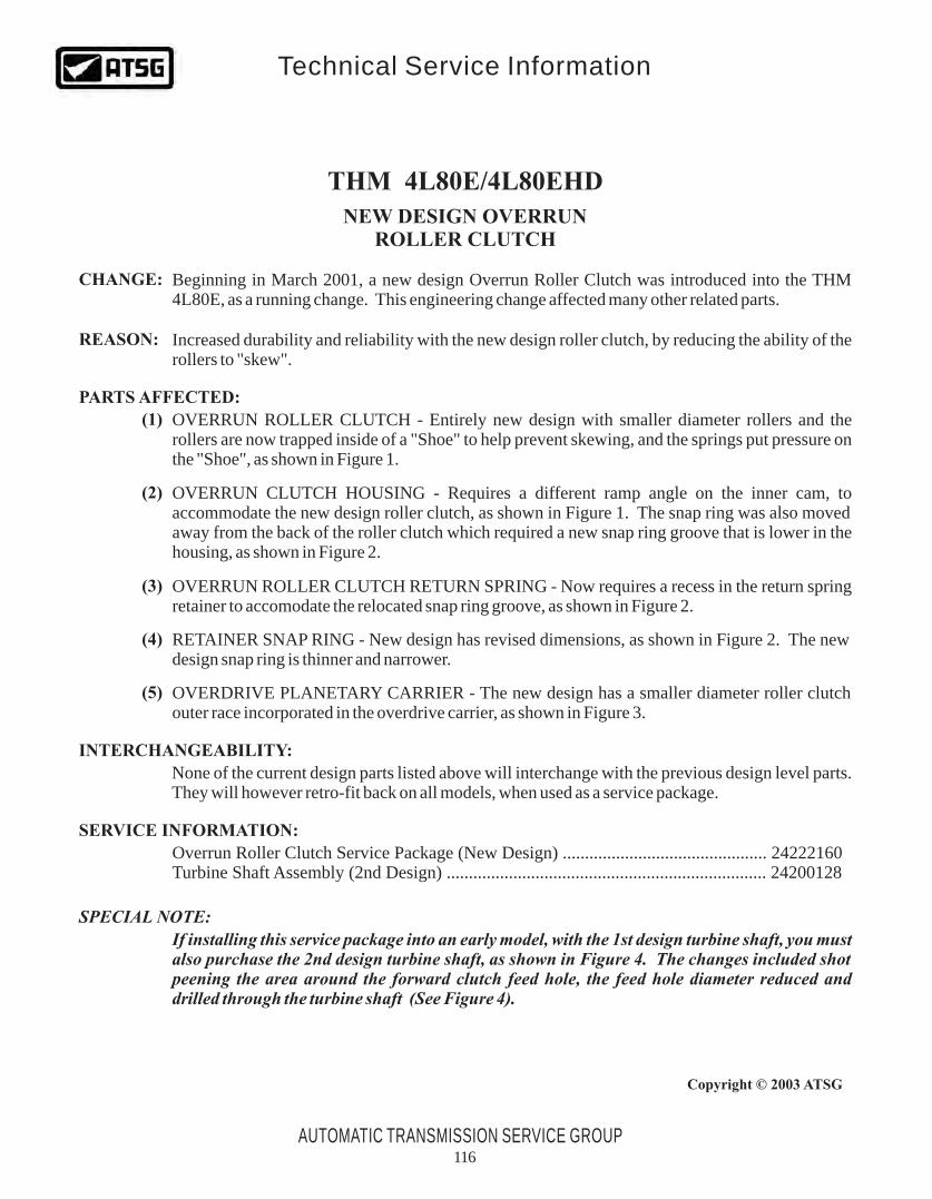
THM 4L80E/4L80EHD
NEW DESIGN OVERRUNROLLER CLUTCH
CHANGE:
REASON:
PARTS AFFECTED:
INTERCHANGEABILITY:
SERVICE INFORMATION:
SPECIAL NOTE:
(1)
(2)
(3)
(4)
(5)
Beginning in March 2001, a new design Overrun Roller Clutch was introduced into the THM 4L80E, as a running change. This engineering change affected many other related parts.
Increased durability and reliability with the new design roller clutch, by reducing the ability of the rollers to "skew".
OVERRUN ROLLER CLUTCH - Entirely new design with smaller diameter rollers and the rollers are now trapped inside of a "Shoe" to help prevent skewing, and the springs put pressure on the "Shoe", as shown in Figure 1.
OVERRUN CLUTCH HOUSING - Requires a different ramp angle on the inner cam, to accommodate the new design roller clutch, as shown in Figure 1. The snap ring was also moved away from the back of the roller clutch which required a new snap ring groove that is lower in the housing, as shown in Figure 2.
OVERRUN ROLLER CLUTCH RETURN SPRING - Now requires a recess in the return spring retainer to accomodate the relocated snap ring groove, as shown in Figure 2.
RETAINER SNAP RING - New design has revised dimensions, as shown in Figure 2. The new design snap ring is thinner and narrower.
OVERDRIVE PLANETARY CARRIER - The new design has a smaller diameter roller clutch outer race incorporated in the overdrive carrier, as shown in Figure 3.
None of the current design parts listed above will interchange with the previous design level parts. They will however retro-fit back on all models, when used as a service package.
Overrun Roller Clutch Service Package (New Design) .............................................. 24222160Turbine Shaft Assembly (2nd Design) ........................................................................ 24200128
If installing this service package into an early model, with the 1st design turbine shaft, you must also purchase the 2nd design turbine shaft, as shown in Figure 4. The changes included shot peening the area around the forward clutch feed hole, the feed hole diameter reduced and drilled through the turbine shaft (See Figure 4).
AUTOMATIC TRANSMISSION SERVICE GROUP
Technical Service Information
Copyright © 2003 ATSG
116
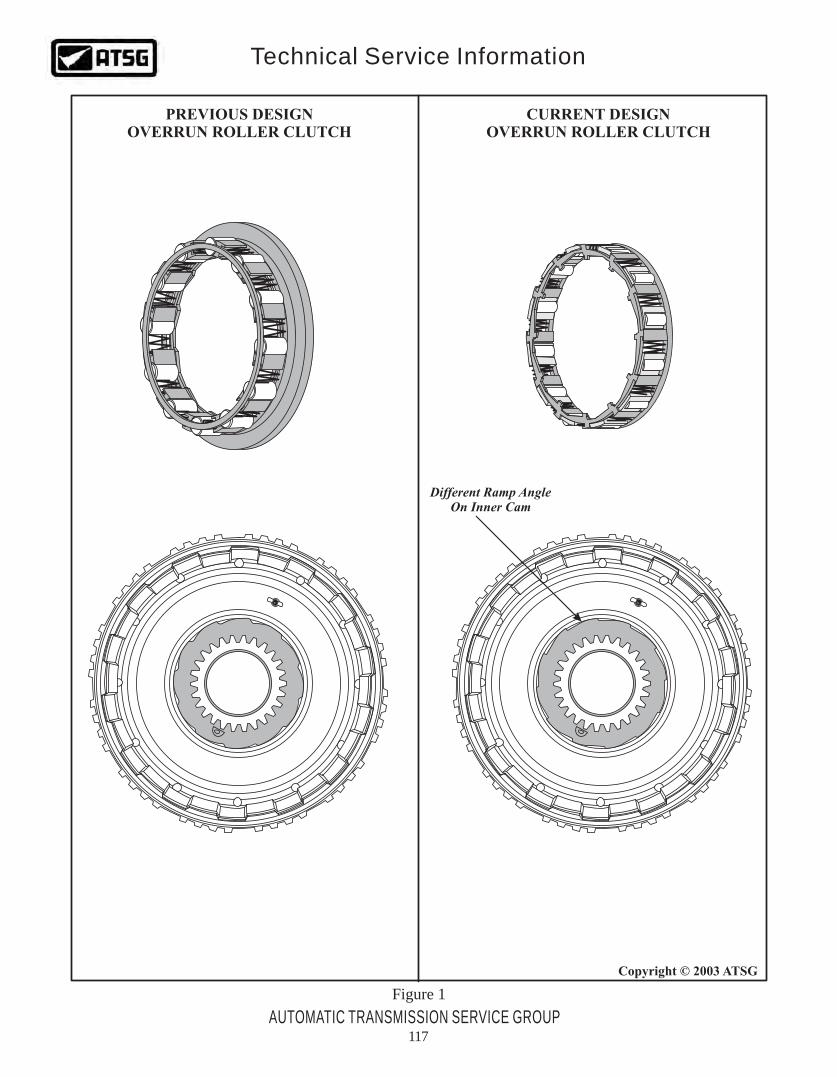
PREVIOUS DESIGNOVERRUN ROLLER CLUTCH
CURRENT DESIGNOVERRUN ROLLER CLUTCH
Figure 1
Different Ramp AngleOn Inner Cam
AUTOMATIC TRANSMISSION SERVICE GROUP
Technical Service Information
Copyright © 2003 ATSG
117

Snap Ring Thickness = .079"Snap Ring Width = .170"
Snap Ring Thickness = .060"Snap Ring Width = .140"
AddedRecess
Added SnapRing Groove
NoRecess
PREVIOUS DESIGN CURRENT DESIGN
Figure 2
AUTOMATIC TRANSMISSION SERVICE GROUP
Technical Service Information
Copyright © 2003 ATSG
118

Approx3.215"
Approx3.025"
PREVIOUS DESIGNOVERDRIVE CARRIER
CURRENT DESIGNOVERDRIVE CARRIER
Figure 3
AUTOMATIC TRANSMISSION SERVICE GROUP
Technical Service Information
Copyright © 2003 ATSG
119

Figure 4
"2ND" DESIGN TURBINE SHAFT
"1ST" DESIGN TURBINE SHAFT
Forward Clutch FeedHole Drilled Through
AUTOMATIC TRANSMISSION SERVICE GROUP
Technical Service Information
Copyright © 2003 ATSG
120