THERMOECONOMIC ANALYSIS OF A WATER TO WATER HEAT …
12
Journal of Thermal Engineering, Vol. 5, No. 3, pp. 198-209, April, 2019 Yildiz Technical University Press, Istanbul, Turkey This paper was recommended for publication in revised form by Regional Editor Ozgen Acikgoz 1 Gas and Gas Installation Program, TOBB Vocational School of Technical Sciences, Karabuk Uni., 78050, Karabuk, TURKEY 2 Automotive Technologies Program, TOBB Vocational School of Technical Sciences, Karabuk Uni., 78050, Karabuk, TURKEY 3 Mechanical Engineering Department, Faculty of Engineering & Architecture, Necmettin Erbakan Uni., 42140, Konya, TURKEY Orcid Id: 0000-0002-3976-8768, 0000-0002-7986-1684, 0000-0002-3409-9534 *E-mail address: [email protected] Manuscript Received 19 December 2017, Accepted 14 March 2018 THERMOECONOMIC ANALYSIS OF A WATER TO WATER HEAT PUMP UNDER DIFFERENT CONDENSER AND EVAPORATOR CONDITIONS B. Aksu 1, *, C. Uysal 2 , H. Kurt 3 ABSTRACT A thermoeconomic analysis of a water to water heat pump are performed under different condenser and evaporator conditions. Experiments are realized for different volumetric inlet temperatures of 14.4, 17 and 19 C and different volumetric flow rates of 50, 100, 150 lt/h for condenser cooling water. Same inlet temperatures with condenser cooling water are used for evaporator water inlet, while constant volumetric flow rate of 100 lt/h is used for each case. Modified Productive Structure Analysis (MOPSA) is used for thermoeconomic analysis. It is found that increases in inlet temperature and in volumetric flow rate cause to decrease in both the unit cost of heat delivered ( H C ) and the unit cost of entropy generation ( S C ). As a result, in the case of in T =14.4 C and = 50 lt/h, H C and S C values are obtained to be 0.0489 $/kWh and 0.0221 $/kWh, respectively, while H C and S C values are obtained to be 0.0385 $/kWh and 0.0175 $/kWh for in T =19 C and = 150 lt/h, respectively. Keywords: Water to Water Heat Pump, Condenser Cooling Water, Thermoeconomic Analysis, MOPSA INTRODUCTION Growing energy demand, limited life time and reservoirs of fossil fuels and environmental effects caused by fossil fuel usage such as greenhouse effect and global warming cause to pay a more attention for alternative energy sources. In this sense, heat pump systems can be considered one of these energy sources because of that they provide cooling or heating by using non-fossil based energy sources. Heat pump systems transfer the energy from lower temperature source to higher temperature source. Different energy sources such as air, water and ground can be used by heat pump systems. To be able to provide the energy transfer from lower temperature source to higher one, heat pump systems consume electricity. Although the performance improvement studies in the manner of thermodynamics are important, the studies for economically assessment of this kind system are also important to be able to evaluate the unit cost of products. Thermoeconomic analysis that combines thermodynamical and economic analysis is an effective tool to evaluate thermal systems. Thermoeconomic analysis provides an information for designers or engineers about the effect of some modifications or malfunctions and dysfunctions on the unit cost of system products. In this sense, several studies about thermoeconomic analysis of heat pump systems have been performed on. Waheed et al. [1] have performed a study to reduce heat pump size and heat loss developed advanced vapor recompression heat pump models. They compared the thermoeconomic and environmental performance of the developed models with the traditional distillation process. As a result, the developed models provided significant energy savings. The total annual costs for the models were 92259 US$, 92835US$, 95454 US$, and cost savings were 33.6%, 29.7% and 24.4%, respectively. Qureshi and Zubair [2] have investigated the thermoeconomic factors for the inventory of the heat exchanger at finite thermal capacities of irreversible refrigerants and heat pumps. As a result, the use of mathematical expressions would be better for determining the effect of the internal dissipation. Kodal et al. [3-4] have conducted performance analyzes using finite time thermodynamic based on a thermoeconomic objective function for irreversible refrigerators and heat pumps. They analytically derived optimum design parameters for the maximum conditions of the objective functions for refrigerators and heat pumps and have discussed the effects of internal irreversibility, economic parameters and external temperatures on global and optimal performance. Teyber et al. [5] have offered an optimization to minimize the permanent magnet and cooling cost in magnetic heat pumps. As a result, a constant temperature
Transcript of THERMOECONOMIC ANALYSIS OF A WATER TO WATER HEAT …

Journal of Thermal Engineering, Vol. 5, No. 3, pp. 198-209, April, 2019 Yildiz Technical University Press, Istanbul, Turkey
This paper was recommended for publication in revised form by Regional Editor Ozgen Acikgoz 1Gas and Gas Installation Program, TOBB Vocational School of Technical Sciences, Karabuk Uni., 78050, Karabuk, TURKEY 2Automotive Technologies Program, TOBB Vocational School of Technical Sciences, Karabuk Uni., 78050, Karabuk, TURKEY 3Mechanical Engineering Department, Faculty of Engineering & Architecture, Necmettin Erbakan Uni., 42140, Konya, TURKEY Orcid Id: 0000-0002-3976-8768, 0000-0002-7986-1684, 0000-0002-3409-9534 *E-mail address: [email protected] Manuscript Received 19 December 2017, Accepted 14 March 2018
THERMOECONOMIC ANALYSIS OF A WATER TO WATER HEAT PUMP UNDER
DIFFERENT CONDENSER AND EVAPORATOR CONDITIONS
B. Aksu1,*, C. Uysal2, H. Kurt3
ABSTRACT
A thermoeconomic analysis of a water to water heat pump are performed under different condenser and
evaporator conditions. Experiments are realized for different volumetric inlet temperatures of 14.4, 17 and 19
C and different volumetric flow rates of 50, 100, 150 lt/h for condenser cooling water. Same inlet temperatures
with condenser cooling water are used for evaporator water inlet, while constant volumetric flow rate of 100 lt/h
is used for each case. Modified Productive Structure Analysis (MOPSA) is used for thermoeconomic analysis. It
is found that increases in inlet temperature and in volumetric flow rate cause to decrease in both the unit cost of
heat delivered ( HC ) and the unit cost of entropy generation ( SC ). As a result, in the case of inT =14.4 C and
= 50 lt/h, HC and SC values are obtained to be 0.0489 $/kWh and 0.0221 $/kWh, respectively, while HC and
SC values are obtained to be 0.0385 $/kWh and 0.0175 $/kWh for inT =19 C and = 150 lt/h, respectively.
Keywords: Water to Water Heat Pump, Condenser Cooling Water, Thermoeconomic Analysis,
MOPSA
INTRODUCTION Growing energy demand, limited life time and reservoirs of fossil fuels and environmental effects
caused by fossil fuel usage such as greenhouse effect and global warming cause to pay a more attention for
alternative energy sources. In this sense, heat pump systems can be considered one of these energy sources
because of that they provide cooling or heating by using non-fossil based energy sources. Heat pump systems
transfer the energy from lower temperature source to higher temperature source. Different energy sources such as
air, water and ground can be used by heat pump systems. To be able to provide the energy transfer from lower
temperature source to higher one, heat pump systems consume electricity. Although the performance
improvement studies in the manner of thermodynamics are important, the studies for economically assessment of
this kind system are also important to be able to evaluate the unit cost of products.
Thermoeconomic analysis that combines thermodynamical and economic analysis is an effective tool to
evaluate thermal systems. Thermoeconomic analysis provides an information for designers or engineers about
the effect of some modifications or malfunctions and dysfunctions on the unit cost of system products. In this
sense, several studies about thermoeconomic analysis of heat pump systems have been performed on.
Waheed et al. [1] have performed a study to reduce heat pump size and heat loss developed advanced
vapor recompression heat pump models. They compared the thermoeconomic and environmental performance of
the developed models with the traditional distillation process. As a result, the developed models provided
significant energy savings. The total annual costs for the models were 92259 US$, 92835US$, 95454 US$, and
cost savings were 33.6%, 29.7% and 24.4%, respectively. Qureshi and Zubair [2] have investigated the
thermoeconomic factors for the inventory of the heat exchanger at finite thermal capacities of irreversible
refrigerants and heat pumps. As a result, the use of mathematical expressions would be better for determining the
effect of the internal dissipation. Kodal et al. [3-4] have conducted performance analyzes using finite time
thermodynamic based on a thermoeconomic objective function for irreversible refrigerators and heat pumps.
They analytically derived optimum design parameters for the maximum conditions of the objective functions for
refrigerators and heat pumps and have discussed the effects of internal irreversibility, economic parameters and
external temperatures on global and optimal performance. Teyber et al. [5] have offered an optimization to
minimize the permanent magnet and cooling cost in magnetic heat pumps. As a result, a constant temperature
Journal of Thermal Engineering, Research Article, Vol. 5, No. 3, pp. 198-209, April, 2019
199
range of 15 K and an optimal magnet configuration for 4.2 kg of gadolinium, using 16.3 kg of permanent magnet
material, they obtained cooling power of 3.3 kW with a second law efficiency of 0.33. Esfahani et al. [6] have
developed a thermoeconomic model of an existing system which has low and high pressure compressors. The
thermoeconomic model has been used to assess the unit cost of the fresh water and cooling to evaluate the
flexibility of the system for fuel allocation from different electricity and heat energy sources. The results showed
that the system with two compressors had high flexibility to allocate the different energy sources when the
availability of the sources was limited for a given value of fresh water and cooling production.Verda et al. [7]
have conducted thermoeconomic analysis for district heating networks operating at low temperatures. The
analyzes were made on simple samples in order to provide a quantitative evaluation of various cost terms
according to user / producer conditions, topology and properties.
Arat and Arslan [8] have investigated geothermal heat pump supported district heating system
exergetically and economically by using NPL and LLC method. The results have showed that 13776 houses
would be heated with this system and it could be an attractive investment for the region. Erbay and Hepbasli [9]
have investigated the ground source heat pump drying system in terms of exergetic and advanced
exergoeconomics. Results showed that total costs could be decrease from 4.008 $/h to 2.569 $/h. For this, the
improvements had to be made at drying tube and condenser. Sayyadi and Nejatolahi [10] have compared and
discussed the results of optimizing by the ways of thermodynamic, thermoeconomic, and both thermodynamic
both thermoeconomic according to the total revenue requirement model (TTR) of the cooling tower supported
with ground source heat pump. Further, the sensitivity of optimized systems to the interest rate, the annual
number of operating hours in cooling mode, the electricity price, and the water price are studied in detail. Erbay
and Hepbasli [11] have found that the total cost was 1.347 $/h and the exergoeconomic factor was 0.029, by
performing an exergoeconomic analysis of the ground source heat pump food dryer. Mastrullo and Renno [12]
have investigated a model of heat pump whose evaporator operates as a photovoltaic collector in the terms of
thermoeconomic and have compared the conventional heat pump with the photovoltaic heat pump
thermoeconomically in the same operating conditions. Akbulut et al. [13] have experimentally and theoretically
investigated exergoeconomic and exergoenvironmental analyses of wall cooling systems fed by a vertical type of
ground source heat pump integrated wall cooling system for cooling mode. The results showed that the energy
and exergy efficient of the whole system were 74.85% and 29.90%, respectively. The external environmental
effects of the whole system were found as 42.6% and the exergoeconomic factor as 77.68%. Qin and Hao [14]
have showed that the coefficient of performance of the sewage source heat-pump system approximates to 4.0.
They have determined that the cost of the system is around 16.77 ¥/m2 and the annual cost of saving is around
444000 ¥. When they examined the thermoeconomic cost of the system, they obtained an average value of 7.8
W/W. Erbay and Hepbasli [15] have compared the performance of the pilot scale air source heat pump food
dryer with the traditional and exergoeconomic aspects. By the results, they have determined that the most
necessary cost to reduce the cost is in the heat recovery unit. Kwak et al. [16] have performed thermoeconomic
analysis of a ground-source heat pump system with a vertical or horizontal ground heat exchanger. Modified
Productive Structure Analysis (MOPSA) method is used for thermoeconomic analysis. They have reported that
the unit cost of heat delivered is 0.063 $/kWh, while the unit cost of electricity supplied to the system is 0.14
$/kWh and the coefficient of performance of the system is 3.27.
In this study, thermoeconomic analysis of a water-to-water heat pump system is performed on under
different condenser and evaporator conditions. Same inlet temperatures of water supplied to condenser and
evaporator are used in the experiments, which are Tin= 14.4 C , 17 C and 19 C . Moreover, different
volumetric flow rates are used for the water stream supplied to the condenser ( =50 lt/h, 100 lt/h and 150 lt/h),
while volumetric flow rates of water stream supplied to evaporator are to be fixed as = 100 lt/h in all
experiments. Modified Productive Structure Analysis (MOPSA) is used for thermoeconomic analysis of the heat
pump system considered in this study. The unit costs of mechanical exergy, thermal exergy, heat delivered and
negentropy are presented and the effects of condenser and evaporator conditions on the unit cost of these terms
are discussed.
SYSTEM DESCRIPTION AND EXPERIMENTAL SETUP
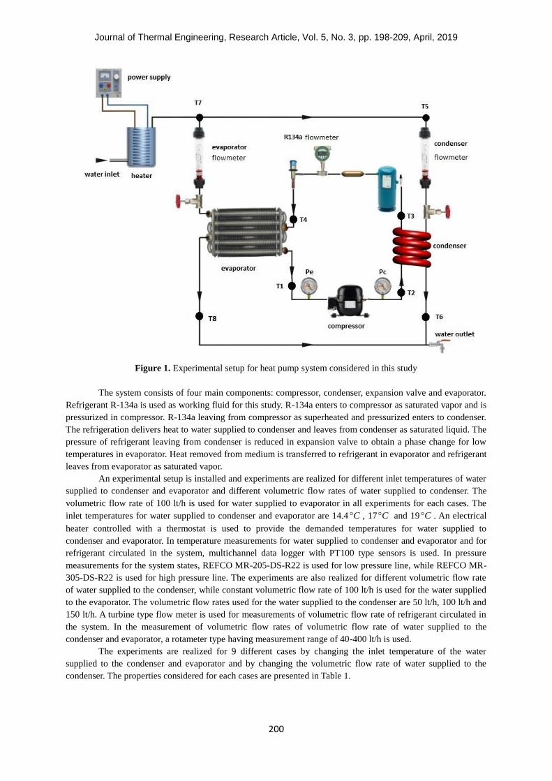
A schematic diagram of experimental setup for the water-to-water heat pump considered in this study is
shown in Figure 1.
Journal of Thermal Engineering, Research Article, Vol. 5, No. 3, pp. 198-209, April, 2019
200
Figure 1. Experimental setup for heat pump system considered in this study
The system consists of four main components: compressor, condenser, expansion valve and evaporator.
Refrigerant R-134a is used as working fluid for this study. R-134a enters to compressor as saturated vapor and is
pressurized in compressor. R-134a leaving from compressor as superheated and pressurized enters to condenser.
The refrigeration delivers heat to water supplied to condenser and leaves from condenser as saturated liquid. The
pressure of refrigerant leaving from condenser is reduced in expansion valve to obtain a phase change for low
temperatures in evaporator. Heat removed from medium is transferred to refrigerant in evaporator and refrigerant
leaves from evaporator as saturated vapor.
An experimental setup is installed and experiments are realized for different inlet temperatures of water
supplied to condenser and evaporator and different volumetric flow rates of water supplied to condenser. The
volumetric flow rate of 100 lt/h is used for water supplied to evaporator in all experiments for each cases. The
inlet temperatures for water supplied to condenser and evaporator are 14.4 C , 17 C and 19 C . An electrical
heater controlled with a thermostat is used to provide the demanded temperatures for water supplied to
condenser and evaporator. In temperature measurements for water supplied to condenser and evaporator and for
refrigerant circulated in the system, multichannel data logger with PT100 type sensors is used. In pressure
measurements for the system states, REFCO MR-205-DS-R22 is used for low pressure line, while REFCO MR-
305-DS-R22 is used for high pressure line. The experiments are also realized for different volumetric flow rate
of water supplied to the condenser, while constant volumetric flow rate of 100 lt/h is used for the water supplied
to the evaporator. The volumetric flow rates used for the water supplied to the condenser are 50 lt/h, 100 lt/h and
150 lt/h. A turbine type flow meter is used for measurements of volumetric flow rate of refrigerant circulated in
the system. In the measurement of volumetric flow rates of volumetric flow rate of water supplied to the
condenser and evaporator, a rotameter type having measurement range of 40-400 lt/h is used.
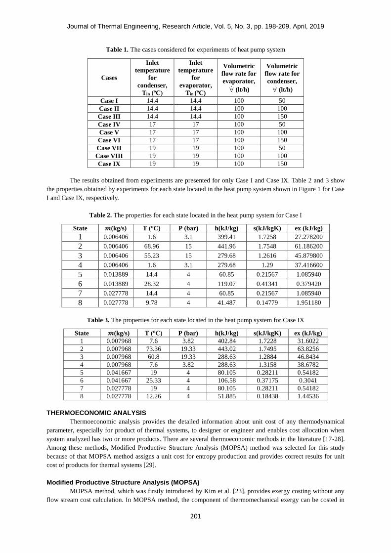
The experiments are realized for 9 different cases by changing the inlet temperature of the water
supplied to the condenser and evaporator and by changing the volumetric flow rate of water supplied to the
condenser. The properties considered for each cases are presented in Table 1.
Journal of Thermal Engineering, Research Article, Vol. 5, No. 3, pp. 198-209, April, 2019
201
Table 1. The cases considered for experiments of heat pump system
Cases
Inlet
temperature
for
condenser,
Tin (ºC)
Inlet
temperature
for
evaporator,
Tin (ºC)
Volumetric
flow rate for
evaporator,
(lt/h)
Volumetric
flow rate for
condenser,
(lt/h)
Case I 14.4 14.4 100 50
Case II 14.4 14.4 100 100
Case III 14.4 14.4 100 150
Case IV 17 17 100 50
Case V 17 17 100 100
Case VI 17 17 100 150
Case VII 19 19 100 50
Case VIII 19 19 100 100
Case IX 19 19 100 150
The results obtained from experiments are presented for only Case I and Case IX. Table 2 and 3 show
the properties obtained by experiments for each state located in the heat pump system shown in Figure 1 for Case
I and Case IX, respectively.
Table 2. The properties for each state located in the heat pump system for Case I
State �̇�(kg/s) T (°C) P (bar) h(kJ/kg) s(kJ/kgK) ex (kJ/kg)
1 0.006406 1.6 3.1 399.41 1.7258 27.278200
2 0.006406 68.96 15 441.96 1.7548 61.186200
3 0.006406 55.23 15 279.68 1.2616 45.879800
4 0.006406 1.6 3.1 279.68 1.29 37.416600
5 0.013889 14.4 4 60.85 0.21567 1.085940
6 0.013889 28.32 4 119.07 0.41341 0.379420
7 0.027778 14.4 4 60.85 0.21567 1.085940
8 0.027778 9.78 4 41.487 0.14779 1.951180
Table 3. The properties for each state located in the heat pump system for Case IX
State �̇�(kg/s) T (°C) P (bar) h(kJ/kg) s(kJ/kgK) ex (kJ/kg)
1 0.007968 7.6 3.82 402.84 1.7228 31.6022
2 0.007968 73.36 19.33 443.02 1.7495 63.8256
3 0.007968 60.8 19.33 288.63 1.2884 46.8434
4 0.007968 7.6 3.82 288.63 1.3158 38.6782
5 0.041667 19 4 80.105 0.28211 0.54182
6 0.041667 25.33 4 106.58 0.37175 0.3041
7 0.027778 19 4 80.105 0.28211 0.54182
8 0.027778 12.26 4 51.885 0.18438 1.44536
THERMOECONOMIC ANALYSIS
Thermoeconomic analysis provides the detailed information about unit cost of any thermodynamical
parameter, especially for product of thermal systems, to designer or engineer and enables cost allocation when
system analyzed has two or more products. There are several thermoeconomic methods in the literature [17-28].
Among these methods, Modified Productive Structure Analysis (MOPSA) method was selected for this study
because of that MOPSA method assigns a unit cost for entropy production and provides correct results for unit
cost of products for thermal systems [29].
Modified Productive Structure Analysis (MOPSA)
MOPSA method, which was firstly introduced by Kim et al. [23], provides exergy costing without any
flow stream cost calculation. In MOPSA method, the component of thermomechanical exergy can be costed in
Journal of Thermal Engineering, Research Article, Vol. 5, No. 3, pp. 198-209, April, 2019
202
separate form as thermal and mechanical exergy costs. Therefore, general exergy balance equation can be written
for MOPSA application as follows:
�̇�𝑥𝐶𝐻𝐸 + ( ∑ �̇�𝑥
𝑇
𝑖𝑛𝑙𝑒𝑡
− ∑ �̇�𝑥𝑇
𝑜𝑢𝑡𝑙𝑒𝑡
) + ( ∑ �̇�𝑥𝑃
𝑖𝑛𝑙𝑒𝑡
− ∑ �̇�𝑥𝑃
𝑜𝑢𝑡𝑙𝑒𝑡
)
+ 𝑇𝑜(∑ �̇�𝑖𝑖𝑛𝑙𝑒𝑡 − ∑ �̇�𝑖𝑜𝑢𝑡𝑙𝑒𝑡 ) = �̇�𝑥𝑊 (1)
In Equation 1, first term on the left side express the chemical exergy of fuel supplied to the system.
Second and third terms on the left side are thermal and mechanical components of thermomechanical exergy of
any stream, respectively. Fourth term on the left side denote exergy destruction of the component considered.
The term on the right side of Equation 1 the exergy value of work, which is equal to the value of work.
Thermoeconomics is an engineering branch that combines thermodynamics and economics analysis.
Therefore, economic analysis should be applied to realize the thermoeconomical analysis of a thermal system. In
this study, the annualized (levelized) cost method proposed by Moran [30] is used to estimate the capital cost of
components. The present worth factor (PWF) and the capital recovery factor (CRF) are given as follows,
respectively:
1
1n
PWFi
(2)
(1 )
1 1
n
n
i iCRF
i
(3)
where i and n terms denote the interest rate and the life time of system, respectively. The salvage value of the
system can be calculated as follows:
SV TCI (4)
where and TCI represent the salvage value ratio and the total capital investment of the system. The present
worth (PW) and the annual capital cost of the system ( AC ) are given as follows, respectively.
PW TCI SV PWF (5)
𝐴�̇� = 𝑃𝑊 × 𝐶𝑅𝐹 (6)
The capital investment cost of overall system is calculated as follows:
�̇�𝑠𝑦𝑠𝑡𝑒𝑚 = 𝜙𝐴�̇�
𝜏 (7)
where and denote the maintenance factor and the total annual number of operating hours of the system at
full load capacity. The capital investment cost rate of kth component of the system can be calculated as follows:
�̇�𝑘 = �̇�𝑠𝑦𝑠𝑡𝑒𝑚𝑃𝐸𝐶𝑘
𝑇𝐶𝐼 (8)
where PEC express the purchased equipment cost of kth component in the system.
The general cost balance equation for MOPSA based adding unit cost of related terms in the exergy
balance equation given in Equation 9 can be written as follows:
Journal of Thermal Engineering, Research Article, Vol. 5, No. 3, pp. 198-209, April, 2019
203
𝐸�̇�𝐶𝐻𝐸𝐶0 + ( ∑ 𝐸�̇�𝑖𝑛𝑇 − ∑ 𝐸�̇�𝑜𝑢𝑡
𝑇
𝑜𝑢𝑡𝑙𝑒𝑡𝑖𝑛𝑙𝑒𝑡
) 𝐶𝑇 + ( ∑ 𝐸�̇�𝑖𝑛𝑃 − ∑ 𝐸�̇�𝑜𝑢𝑡
𝑃
𝑜𝑢𝑡𝑙𝑒𝑡𝑖𝑛𝑙𝑒𝑡
) 𝐶𝑃
+𝑇0(∑ �̇�𝑖𝑛𝑖𝑛𝑙𝑒𝑡 − ∑ �̇�𝑜𝑢𝑡𝑜𝑢𝑡𝑙𝑒𝑡 )𝐶𝑆 + �̇�𝑘 = 𝐸�̇�𝑊𝐶𝑊 (9)
whereT and P superscripts represent thermal and mechanical components of thermomechanical exergy,
respectively. 0C , SC and WC are the unit exergy cost of fuel, entropy and work, respectively. TC and PC are
also the unit exergy cost of thermal and mechanical components of thermomechanical exergy, respectively.
MOPSA Application for Water-to-Water Heat Pump
The exergy balance equations are obtained by applying the general exergy balance equation given in
Equation 1 to each components of the heat pump system shown in Figure 1. The obtained equations are given as
follows:
Compressor:
(𝐸�̇�1𝑇 − 𝐸�̇�2
𝑇) + (𝐸�̇�1𝑃 − 𝐸�̇�2
𝑃) + 𝑇0(�̇�1 − �̇�2) = 𝐸�̇�𝑊 (10)
Condenser:
(𝐸�̇�2𝑇 − 𝐸�̇�3
𝑇 + 𝐸�̇�5𝑇 − 𝐸�̇�6
𝑇) + (𝐸�̇�2𝑃 − 𝐸�̇�3
𝑃 + 𝐸�̇�5𝑃 − 𝐸�̇�6
𝑃)
+𝑇0(�̇�2 − �̇�3 + �̇�5 − �̇�6) = 0 (11)
Expansion valve:
(𝐸�̇�3𝑇 − 𝐸�̇�4
𝑇) + (𝐸�̇�3𝑃 − 𝐸�̇�4
𝑃) + 𝑇0(�̇�3 − �̇�4) = 0 (12)
Evaporator:
(𝐸�̇�4𝑇 − 𝐸�̇�1
𝑇 + 𝐸�̇�7𝑇 − 𝐸�̇�8
𝑇)𝐶𝑇 + (𝐸�̇�4𝑃 − 𝐸�̇�1
𝑃 + 𝐸�̇�7𝑃 − 𝐸�̇�8
𝑃)
+𝑇0(�̇�4 − �̇�1 + �̇�7 − �̇�8) = 0 (13)
In this study, for economic analysis, the interest ratio (i) and the life time of the system (n) are assumed
to be 10% and 5 years, respectively. In addition; the salvage value ratio ( ), the maintenance factor ( ) and the
total annual number of operating hours of the system at full load capacity () are selected to be 12%, 1.06 and
2880 hours, respectively.
The cost balance equations are obtained by applying the general cost balance equation given in
Equation 9 to each components of the heat pump system illustrated in Figure 1 and are given as follows:
Compressor:
(𝐸�̇�1𝑇 − 𝐸�̇�2
𝑇)𝐶𝑇 + (𝐸�̇�1𝑃 − 𝐸�̇�2
𝑃)𝐶𝑃 + [𝑇0(�̇�1 − �̇�2)]𝐶𝑆 + �̇�𝑐𝑜𝑚 = 𝐸�̇�𝑊𝐶𝑊 (14)
Condenser:
(𝐸�̇�2𝑇 − 𝐸�̇�3
𝑇)𝐶𝑇 + (𝐸�̇�2𝑃 − 𝐸�̇�3
𝑃)𝐶𝑃 − �̇�𝑟𝑜𝑜𝑚𝐶𝐻 + [𝑇0(�̇�2 − �̇�3)]𝐶𝑆 + �̇�𝑐𝑛𝑑 = 0 (15)
Expansion valve:
(𝐸�̇�3𝑇 − 𝐸�̇�4
𝑇)𝐶𝑇 + (𝐸�̇�3𝑃 − 𝐸�̇�4
𝑃)𝐶𝑃 + [𝑇0(�̇�3 − �̇�4)]𝐶𝑆 + �̇�𝑒𝑥𝑝 = 0 (16)
Journal of Thermal Engineering, Research Article, Vol. 5, No. 3, pp. 198-209, April, 2019
204
Evaporator:
(𝐸�̇�4𝑇 − 𝐸�̇�1
𝑇)𝐶𝑇 + (𝐸�̇�4𝑃 − 𝐸�̇�1
𝑃)𝐶𝑃 + (𝐸�̇�7 − 𝐸�̇�8). 0 + [𝑇0(�̇�4 − �̇�1)]𝐶𝑆 + �̇�𝑒 𝑣𝑎 = 0 (17)
whereroomQ term represents the heat transfer rate delivered to medium heated and it is formulated as follows:
�̇�𝑟𝑜𝑜𝑚 = (𝐸�̇�𝑇6 − 𝐸�̇�𝑇
5) + (𝐸�̇�𝑃6 − 𝐸�̇�𝑃
5) + 𝑇0(�̇�6 − �̇�5) (18)
With writing from Equation 14 to Equation 17, all cost balance equations required to calculate the
unknown unit cost parameters assigned as TC , PC , SC and HC are obtained. The value of the unit cost of
electricity supplied to the system ( WC ) is 0.0586 $/kWh [31]. The unit cost of heat gained by evaporator is
assumed to be 0, similarly with Reference [16].
The overall cost balance equation is obtained by summing Equation 14 to Equation 17 as follows:
−�̇�𝑟𝑜𝑜𝑚𝐶𝐻 + ∑ �̇�𝑘 = 𝐸�̇�𝑊𝐶𝑊 (19)
The unit cost of heat obtained by solving Equation 14 to Equation 17 should be same with the result
obtained by Equation 19.
RESULTS AND DISCUSSION
The effect of volumetric flow rate and inlet temperature of condenser cooling water on the unit cost of
heat delivered to medium by a water-to-water heat pump system is investigated. Three different volumetric
volume rates ( = 50 lt/h, 100 lt/h and 150 lt/h) and three different inlet temperatures ( inT = 14 C , 17 C and 19
C ) of condenser cooling water are considered. For evaporator, same inlet temperatures are used with that of
condenser for each case. However, constant volumetric flow rate of 100 lt/h are used for each case. By this way,
the exergy and thermoeconomic analyses are applied for 9 different cases of the heat pump system. However, the
results obtained for only Case I and Case IX are presented in this paper.
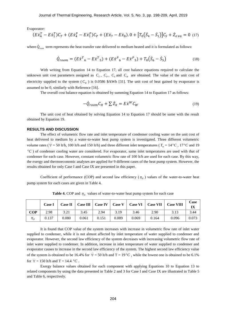
Coefficient of performance (COP) and second law efficiency ( II ) values of the water-to-water heat
pump system for each cases are given in Table 4.
Table 4. COP and II values of water-to-water heat pump system for each case
Case I Case II Case III Case IV Case V Case VI Case VII Case VIII Case
IX
COP 2.98 3.21 3.45 2.94 3.19 3.46 2.90 3.13 3.44
II 0.137 0.080 0.061 0.151 0.089 0.069 0.164 0.096 0.073
It is found that COP value of the system increases with increase in volumetric flow rate of inlet water
supplied to condenser, while it is not almost affected by inlet temperature of water supplied to condenser and
evaporator. However, the second law efficiency of the system decreases with increasing volumetric flow rate of
inlet water supplied to condenser. In addition, increase in inlet temperature of water supplied to condenser and
evaporator causes to increase in the second law efficiency of the system. The highest second law efficiency value
of the system is obtained to be 16.4% for = 50 lt/h and T = 19 C , while the lowest one is obtained to be 6.1%
for = 150 lt/h and T = 14.4 C .
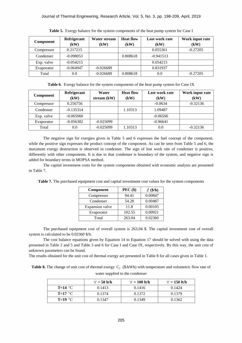
Exergy balance values obtained for each component with applying Equations 10 to Equation 13 to
related components by using the data presented in Table 2 and 3 for Case I and Case IX are illustrated in Table 5
and Table 6, respectively.
Journal of Thermal Engineering, Research Article, Vol. 5, No. 3, pp. 198-209, April, 2019
205
Table 5. Exergy balance for the system components of the heat pump system for Case I
Component Refrigerant
(kW)
Water stream
(kW)
Heat flow
(kW)
Lost work rate
(kW)
Work input rate
(kW)
Compressor 0.217215 0.055361 -0.27205
Condenser -0.098053 0.808618 -0.941513
Exp. valve -0.054215 0.054215
Evaporator -0.064947 -0.026689 0.831937
Total 0.0 -0.026689 0.808618 0.0 -0.27205
Table 6. Exergy balance for the system components of the heat pump system for Case IX
Component Refrigerant
(kW)
Water
stream (kW)
Heat flow
(kW)
Lost work rate
(kW)
Work input rate
(kW)
Compressor 0.256756 -0.0634 -0.32136
Condenser -0.135314 1.10313 1.09487
Exp. valve -0.065060 -0.06506
Evaporator -0.056382 -0.025099 -0.96641
Total 0.0 -0.025099 1.10313 0.0 -0.32136
The negative sign for exergies given in Table 5 and 6 expresses the fuel concept of the component,
while the positive sign expresses the product concept of the component. As can be seen from Table 5 and 6, the
maximum exergy destruction is observed in condenser. The sign of lost work rate of condenser is positive,
differently with other components. It is due to that condenser is boundary of the system, and negative sign is
added for boundary terms in MOPSA method.
The capital investment costs for the system components obtained with economic analysis are presented
in Table 7.
Table 7. The purchased equipment cost and capital investment cost values for the system components
Component PEC ($) Z ($/h)
Compressor 94.41 0.00847
Condenser 54.28 0.00487
Expansion valve 11.8 0.00105
Evaporator 102.55 0.00921
Total 263.04 0.02360
The purchased equipment cost of overall system is 263.04 $. The capital investment cost of overall
system is calculated to be 0.02360 $/h.
The cost balance equations given by Equation 14 to Equation 17 should be solved with using the data
presented in Table 2 and 5 and Table 3 and 6 for Case I and Case IX, respectively. By this way, the unit cost of
unknown parameters can be found.
The results obtained for the unit cost of thermal exergy are presented in Table 8 for all cases given in Table 1.
Table 8. The change of unit cost of thermal exergy TC ($/kWh) with temperature and volumetric flow rate of
water supplied to the condenser
= 50 lt/h = 100 lt/h = 150 lt/h
T=14 C 0.1413 0.1416 0.1424
T=17 C 0.1374 0.1372 0.1379
T=19 C 0.1347 0.1349 0.1362
Journal of Thermal Engineering, Research Article, Vol. 5, No. 3, pp. 198-209, April, 2019
206
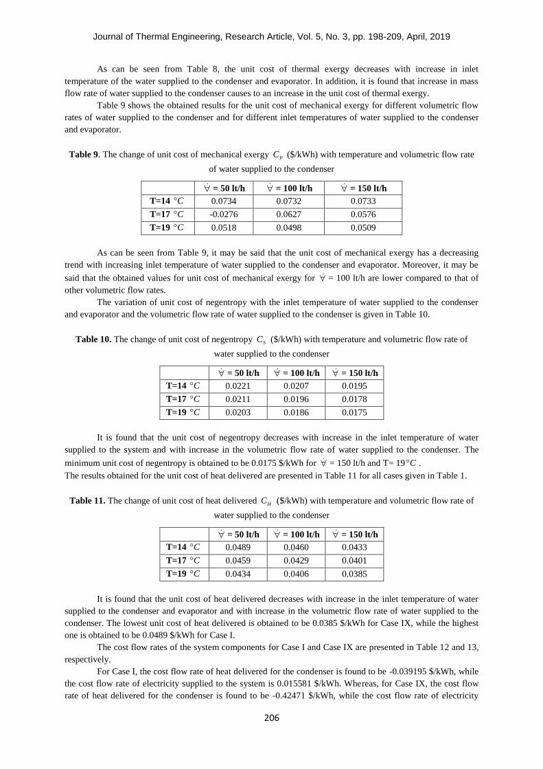
As can be seen from Table 8, the unit cost of thermal exergy decreases with increase in inlet
temperature of the water supplied to the condenser and evaporator. In addition, it is found that increase in mass
flow rate of water supplied to the condenser causes to an increase in the unit cost of thermal exergy.
Table 9 shows the obtained results for the unit cost of mechanical exergy for different volumetric flow
rates of water supplied to the condenser and for different inlet temperatures of water supplied to the condenser
and evaporator.
Table 9. The change of unit cost of mechanical exergy PC ($/kWh) with temperature and volumetric flow rate
of water supplied to the condenser
= 50 lt/h = 100 lt/h = 150 lt/h
T=14 C 0.0734 0.0732 0.0733
T=17 C -0.0276 0.0627 0.0576
T=19 C 0.0518 0.0498 0.0509
As can be seen from Table 9, it may be said that the unit cost of mechanical exergy has a decreasing
trend with increasing inlet temperature of water supplied to the condenser and evaporator. Moreover, it may be
said that the obtained values for unit cost of mechanical exergy for = 100 lt/h are lower compared to that of
other volumetric flow rates.
The variation of unit cost of negentropy with the inlet temperature of water supplied to the condenser
and evaporator and the volumetric flow rate of water supplied to the condenser is given in Table 10.
Table 10. The change of unit cost of negentropy SC ($/kWh) with temperature and volumetric flow rate of
water supplied to the condenser
= 50 lt/h = 100 lt/h = 150 lt/h
T=14 C 0.0221 0.0207 0.0195
T=17 C 0.0211 0.0196 0.0178
T=19 C 0.0203 0.0186 0.0175
It is found that the unit cost of negentropy decreases with increase in the inlet temperature of water
supplied to the system and with increase in the volumetric flow rate of water supplied to the condenser. The
minimum unit cost of negentropy is obtained to be 0.0175 $/kWh for = 150 lt/h and T= 19 C .
The results obtained for the unit cost of heat delivered are presented in Table 11 for all cases given in Table 1.
Table 11. The change of unit cost of heat delivered HC ($/kWh) with temperature and volumetric flow rate of
water supplied to the condenser
= 50 lt/h = 100 lt/h = 150 lt/h
T=14 C 0.0489 0.0460 0.0433
T=17 C 0.0459 0.0429 0.0401
T=19 C 0.0434 0.0406 0.0385
It is found that the unit cost of heat delivered decreases with increase in the inlet temperature of water
supplied to the condenser and evaporator and with increase in the volumetric flow rate of water supplied to the
condenser. The lowest unit cost of heat delivered is obtained to be 0.0385 $/kWh for Case IX, while the highest
one is obtained to be 0.0489 $/kWh for Case I.
The cost flow rates of the system components for Case I and Case IX are presented in Table 12 and 13,
respectively.
For Case I, the cost flow rate of heat delivered for the condenser is found to be -0.039195 $/kWh, while
the cost flow rate of electricity supplied to the system is 0.015581 $/kWh. Whereas, for Case IX, the cost flow
rate of heat delivered for the condenser is found to be -0.42471 $/kWh, while the cost flow rate of electricity
Journal of Thermal Engineering, Research Article, Vol. 5, No. 3, pp. 198-209, April, 2019
207
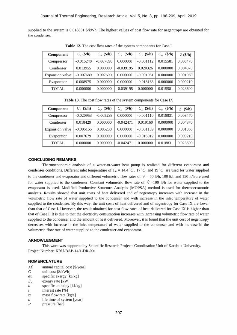
supplied to the system is 0.018831 $/kWh. The highest values of cost flow rate for negentropy are obtained for
the condenser.
Table 12. The cost flow rates of the system components for Case I
Component TC ($/h) PC ($/h) HC ($/h) SC ($/h) WC ($/h) Z ($/h)
Compressor -0.015240 -0.007690 0.000000 -0.001112 0.015581 0.008470
Condenser 0.013955 0.000000 -0.039195 0.020326 0.000000 0.004870
Expansion valve -0.007689 0.007690 0.000000 -0.001051 0.000000 0.001050
Evaporator 0.008975 0.000000 0.000000 -0.018163 0.000000 0.009210
TOTAL 0.000000 0.000000 -0.039195 0.000000 0.015581 0.023600
Table 13. The cost flow rates of the system components for Case IX
Component TC ($/h) PC ($/h) HC ($/h) SC ($/h) WC ($/h) Z ($/h)
Compressor -0.020953 -0.005238 0.000000 -0.001110 0.018831 0.008470
Condenser 0.018429 0.000000 -0.042471 0.019160 0.000000 0.004870
Expansion valve -0.005155 0.005238 0.000000 -0.001139 0.000000 0.001050
Evaporator 0.007679 0.000000 0.000000 -0.016912 0.000000 0.009210
TOTAL 0.000000 0.000000 -0.042471 0.000000 0.018831 0.023600
CONCLUDING REMARKS
Thermoeconomic analysis of a water-to-water heat pump is realized for different evaporator and
condenser conditions. Different inlet temperature of Tin = 14.4 C , 17 C and 19 C are used for water supplied
to the condenser and evaporator and different volumetric flow rates of = 50 lt/h, 100 lt/h and 150 lt/h are used
for water supplied to the condenser. Constant volumetric flow rate of =100 lt/h for water supplied to the
evaporator is used. Modified Productive Structure Analysis (MOPSA) method is used for thermoeconomic
analysis. Results showed that unit costs of heat delivered and of negentropy increases with increase in the
volumetric flow rate of water supplied to the condenser and with increase in the inlet temperature of water
supplied to the condenser. By this way, the unit costs of heat delivered and of negentropy for Case IX are lower
than that of Case I. However, the result obtained for cost flow rates of heat delivered for Case IX is higher than
that of Case I. It is due to that the electricity consumption increases with increasing volumetric flow rate of water
supplied to the condenser and the amount of heat delivered. Moreover, it is found that the unit cost of negentropy
decreases with increase in the inlet temperature of water supplied to the condenser and with increase in the
volumetric flow rate of water supplied to the condenser and evaporator.
AKNOWLEGMENT
This work was supported by Scientific Research Projects Coordination Unit of Karabuk University.
Project Number: KBU-BAP-14/1-DR-001
NOMENCLATURE
𝐴�̇� annual capital cost [$/year]
C unit cost [$/kWh]
ex specific exergy [kJ/kg]
�̇�𝑥 exergy rate [kW]
h specific enthalpy [kJ/kg]
i interest rate [%]
�̇� mass flow rate [kg/s]
n life time of system [year]
P pressure [bar]

Journal of Thermal Engineering, Research Article, Vol. 5, No. 3, pp. 198-209, April, 2019
208
s specific entropy [kJ/kgK]
�̇� entropy rate [kW/K]
T temperature [ C ]
�̇� capital investment cost rate [$/h]
salvage value [%]
total annual number of operating hour of system [h]
maintenance factor
cnd condenser
com compressor
exp expansion valve
eva evaporator
H heat
in inlet
P mechanical
S entropy
T thermal
W work
0 dead state
CHE chemical
P mechanical
T thermal
W work
CRF capital recovery factor
MOPSA modified productive structure analysis
PEC purchased equipment cost
PW present worth
PWF present worth factor
SV salvage value
TCI total capital investment
REFERENCES
[1] Waheed, M. A., Oni, A. O., Adejuyigbe, S. B., Adewumi, B. A., Fadare, D. A. (2014). Performance
enhancement of vapor recompression heat pump. Applied energy, 114, 69-79.
[2] Qureshi, B. A., Zubair, S. M. (2013). Cost optimization of heat exchanger inventory for mechanical
subcooling refrigeration cycles. International Journal of Refrigeration, 36(4), 1243-1253.
[3] Kodal, A., Sahin, B., Ekmekci, I., Yilmaz, T. (2003). Thermoeconomic optimization for irreversible
absorption refrigerators and heat pumps. Energy Conversion and Management, 44(1), 109-123.
[4] Kodal, A., Sahin, B., Yilmaz, T. (2000). Effects of internal irreversibility and heat leakage on the finite time
thermoeconomic performance of refrigerators and heat pumps. Energy Conversion and Management, 41(6), 607-
619.
[5] Teyber, R., Trevizoli, P. V., Christiaanse, T. V., Govindappa, P., Niknia, I., Rowe, A. (2017). Permanent
magnet design for magnetic heat pumps using total cost minimization. Journal of Magnetism and Magnetic
Materials, 442, 87-96.
[6] Esfahani, I. J., Yoo, C. (2014). A highly efficient combined multi-effect evaporation-absorption heat pump
and vapor-compression refrigeration part 2: Thermoeconomic and flexibility analysis. Energy, 75, 327-337.
[7] Verda, V., Caccin, M., Kona, A. (2016). Thermoeconomic cost assessment in future district heating
networks. Energy, 117, 485-491.
[8] Arat, H., Arslan, O. (2017). Exergoeconomic analysis of district heating system boosted by the geothermal
heat pump. Energy, 119, 1159-1170.
[9] Erbay, Z., Hepbasli, A. (2017). Assessment of cost sources and improvement potentials of a ground-source
heat pump food drying system through advanced exergoeconomic analysis method. Energy, 127, 502-515.
[10] Sayyadi, H., & Nejatolahi, M. (2011). Thermodynamic and thermoeconomic optimization of a cooling
tower-assisted ground source heat pump. Geothermics, 40(3), 221-232.
[11] Erbay, Z., Hepbasli, A. (2017). Exergoeconomic evaluation of a ground-source heat pump food dryer at
varying dead state temperatures. Journal of cleaner production, 142, 1425-1435.
Journal of Thermal Engineering, Research Article, Vol. 5, No. 3, pp. 198-209, April, 2019
209
[12] Mastrullo, R., Renno, C. (2010). A thermoeconomic model of a photovoltaic heat pump. Applied Thermal
Engineering, 30(14-15), 1959-1966.
[13] Akbulut, U., Utlu, Z., Kincay, O. (2016). Exergoenvironmental and exergoeconomic analyses of a vertical
type ground source heat pump integrated wall cooling system. Applied Thermal Engineering, 102, 904-921.
[14] Qin N., Hao P. Z. (2017). The operation characteristics of sewage source heat pump system and the analysis
of its thermal economic benefits. Applied Thermal Engineering. 124, 1083-1089
[15] Erbay Z., Hepbaşlı A. (2017). Advanced exergoeconomic evaluation of a heat pump food dryer. Biosystems
Engineering. 124, 29-39
[16] Kwak, H. Y., You, Y., Oh, S. D., Jang, H. N. (2014). Thermoeconomic analysis of ground‐ source heat
pump systems. International Journal of Energy Research, 38(2), 259-269.
[17] von Spakovsky M. R., Evans R. B. (1993). Engineering functional analysis-part I. ASME J Energy Resour
Technol. 155, 86-92.
[18] Rosen, M. A., Dincer, I. (2003). Exergy–cost–energy–mass analysis of thermal systems and processes.
Energy Conversion and Management, 44(10), 1633-1651.
[19] Tsatsaronis G., Lin L., Pisa J. (1993). Exergy costing in exergoeconomics. ASME J Energy Resour
Technol. 155, 9-16.
[20] Tsatsaronis, G., Moran, M. J. (1997). Exergy-aided cost minimization. Energy Conversion and
Management, 38(15-17), 1535-1542.
[21] Tsatsaronis, G., Park, M. H. (2002). On avoidable and unavoidable exergy destructions and investment
costs in thermal systems. Energy Conversion and Management, 43(9-12), 1259-1270.
[22] Tsatsaronis G., Lin L. (1990). On exergy costing in exergoeconomics. In: Tsatsaronis G, Bajura RA,
Kenney WF, Reistad GM, editors. Computer-aided energy systems analysis. New York: ASME, 1-11.
[23] Kim, S. M., Oh, S. D., Kwon, Y. H., Kwak, H. Y. (1998). Exergoeconomic analysis of thermal systems.
Energy, 23(5), 393-406.
[24] Lazzaretto A., Tsatsaronis G. (1997). On the quest for objective equations in exergy costing. In:
Ramalingam ML, Lage JG, Mei VC, Chapman JN, editors. Proceedings of the ASME advanced energy systems
division. New York: ASME, 413-428.
[25] Lazzaretto A., Tsatsaronis G. (1999). On the calculation of efficiencies and costs in thermal systems. In:
Aceves SM, Garimella S, Peterson R, editors. Proceedings of the ASME advanced energy systems division. New
York: ASME, 421-430.
[26] Erlach, B., Serra, L., Valero, A. (1999). Structural theory as standard for thermoeconomics. Energy
Conversion and Management, 40(15-16), 1627-1649.
[27] Lozano, M. A., Valero, A. (1993). Theory of the exergetic cost. Energy, 18(9), 939-960.
[28] Frangopoulos, C. A. (1987). Thermo-economic functional analysis and optimization. Energy, 12(7), 563-
571.
[29] Uysal, C., Kurt, H., Kwak, H. Y. (2017). Exergetic and thermoeconomic analyses of a coal-fired power
plant. International Journal of Thermal Sciences, 117, 106-120.
[30] Moran, M. J. (1982). Availability analysis: a guide to efficient energy use. Englewood Cliffs NJ, Prentice
Hall,
[31] Enerjisa Başkent Electricity Retail Sales Co.