Thermal analytical winding size optimization for different conductor shapes
18
ARCHIVES OF ELECTRICAL ENGINEERING VOL. 64(2), pp. 197-214 (2015) DOI 10.1515/aee-2015-0017 Thermal analytical winding size optimization for different conductor shapes RAFAL P. WOJDA ABB Corporate Research Center, DMPC R&D Team Starowislna 13a, 31-038, Kraków e-mail: [email protected] (Received: 10.09.2014, revised: 25.11.2014) Abstract. The aim of this paper is to derive an analytical equations for the temperature dependent optimum winding size of inductors conducting high frequency ac sinusoidal currents. Derived analytical equations are useful designing tool for research and development engineers because windings made of foil, square-wire, and solid-round-wire windings are considered. Temperature dependent Dowell’s equation for the ac-to-dc winding resistance ratio is given and approximated. Thermally dependent analytical equations for the optimum foil thickness, as well as valley thickness and diameter of the square-wire and solid-round-wire windings are derived from approximated thermally dependent ac-to-dc winding resistance ratios. Minimum winding ac resistance of the foil winding and local minimum of the winding ac resistance of the solid-round-wire winding are verified with Maxwell 3D Finite Element Method simulations. Key words: Dowell’s equation, Eddy currents, FEM, inductors, optimization, proximity effect, skin effect, thermal effects, winding losses 1. Introduction Power inductors are important elements in power conversion process. This is because their ability to store the magnetic energy in the magnetic field blocks the flow of the alternating currents. Moreover, power inductors along with the capacitors form a resonant circuit, which shapes the voltage in the power amplifier, or as a filter, which shapes the current waveform in the power converter. Additionally power inductors and capacitors are used in impedance matching, where the active devices are matched to the load or another power stage of the power system [1-3]. They are also used in the noise filtering [4-6]. Common failure mechanisms in inductors are mainly owing to excessive temperature rise [7, 8]. The excessive temperature causes cracks in the ferrite core and hence decreases the inductance of the inductor or the transformer. The inductance reduced due to the cracks of the core results in increased peak of the current in the winding and cause unexpected current stresses in the active devices that may lead to destruction of the active device. Therefore, in the design process of the power inductors beside magnetic requirements, the thermal limita- tions should be also taken into the consideration. Brought to you by | University of Otago Authenticated Download Date | 7/6/15 12:34 PM
-
Upload
setaresohail -
Category
Documents
-
view
219 -
download
1
Transcript of Thermal analytical winding size optimization for different conductor shapes

ARCHIVES OF ELECTRICAL ENGINEERING VOL. 64(2), pp. 197-214 (2015)
DOI 10.1515/aee-2015-0017
Thermal analytical winding size optimization for different conductor shapes
RAFAL P. WOJDA
ABB Corporate Research Center, DMPC R&D Team
Starowislna 13a, 31-038, Kraków e-mail: [email protected]
(Received: 10.09.2014, revised: 25.11.2014)
Abstract. The aim of this paper is to derive an analytical equations for the temperature dependent optimum winding size of inductors conducting high frequency ac sinusoidal currents. Derived analytical equations are useful designing tool for research and development engineers because windings made of foil, square-wire, and solid-round-wire windings are considered. Temperature dependent Dowell’s equation for the ac-to-dc winding resistance ratio is given and approximated. Thermally dependent analytical equations for the optimum foil thickness, as well as valley thickness and diameter of the square-wire and solid-round-wire windings are derived from approximated thermally dependent ac-to-dc winding resistance ratios. Minimum winding ac resistance of the foil winding and local minimum of the winding ac resistance of the solid-round-wire winding are verified with Maxwell 3D Finite Element Method simulations. Key words: Dowell’s equation, Eddy currents, FEM, inductors, optimization, proximity effect, skin effect, thermal effects, winding losses
1. Introduction Power inductors are important elements in power conversion process. This is because their ability to store the magnetic energy in the magnetic field blocks the flow of the alternating currents. Moreover, power inductors along with the capacitors form a resonant circuit, which shapes the voltage in the power amplifier, or as a filter, which shapes the current waveform in the power converter. Additionally power inductors and capacitors are used in impedance matching, where the active devices are matched to the load or another power stage of the power system [1-3]. They are also used in the noise filtering [4-6]. Common failure mechanisms in inductors are mainly owing to excessive temperature rise [7, 8]. The excessive temperature causes cracks in the ferrite core and hence decreases the inductance of the inductor or the transformer. The inductance reduced due to the cracks of the core results in increased peak of the current in the winding and cause unexpected current stresses in the active devices that may lead to destruction of the active device. Therefore, in the design process of the power inductors beside magnetic requirements, the thermal limita-tions should be also taken into the consideration.
Brought to you by | University of OtagoAuthenticated
Download Date | 7/6/15 12:34 PM

Rafal P. Wojda Arch. Elect. Eng.
198
Power losses in inductors are caused by dc and ac currents flow in the winding, hysteresis and eddy currents loss in the magnetic core, as well as due to the dielectric losses in the insulators of the winding and core. For the high power inductors, from aforementioned losses, significant role plays the winding losses [9-21, 31-36]. While core and dielectric loss are decreased by selection of low-loss materials, the winding losses are significantly reduced by optimization of the winding conductor size [16, 17, 19]. Two approaches for winding size optimization and inductor winding loss minimization are known in the high frequency and high power inductor designing process. First approach, consider utilization of computer-aided design, where 2D/3D model of the inductor is solved directly from Maxwell’s equations utilizing finite element methods (FEM) [22-24, 30]. In this method solution is accurate but adaptation of the solution to the other cases is a very difficult task. Additionally, FEM approach is very time and memory consuming. Second approach is utilization of analytical equations in designing process. This approach gives similar results to FEM simulations and measurements [23-28] and winding optimization is almost instant and can be performed without using computer. Additionally, analytical equations gives a lot of insight into various dependencies of winding resistances and they can be easily used in industrial environment. The most commonly used theory considering winding resistance was introduced by Dowell in 1966 [9]. Dowell determined directly from the Maxwell’s equation the magnetic flux N cutting the winding space, from which he derived winding impedance based on the voltage induced in the conductor due to magnetic flux N. In his theory, Dowell derived equations based on the assumption that the magnetic field in the inductor is parallel to the conductor, and as a result the curvature, end, and edge effects are neglected. Moreover, Dowell assumed that the winding operates at room temperature. This paper consider the analytical optimization of the inductor winding size utilizing temperature dependent Dowell’s equation for sinusoidal currents. Utilization of the derived equations for the optimum conductor size can be applied in design of the magnetic com-ponents used in inverters, power amplifiers, filtering and matching circuits. The main objectives of this paper are: • adaptation of thermal effect into Dowell’s equation; • approximate thermally dependent Dowell’s equation; • derive temperature dependent optimum foil thickness; • derive temperature dependent valley thickness of the square-wire winding; • derive temperature dependent valley diameter of the solid-round-wire winding; • verify derived thermally dependent Dowell’s equations for the foil and the solid-round-
wire winding using Maxwell 3D Finite Element Method (FEM); • verify the ac winding resistance of derived equation for the temperature dependent opti-
mum foil thickness using 3D FEM; • verify the ac winding resistance of derived equations of the temperature dependent valley
diameter of the solid-round-wire winding using 3D FEM.
Brought to you by | University of OtagoAuthenticated
Download Date | 7/6/15 12:34 PM

Vol. 64 (2015) Thermal analytical winding size optimization for different conductor shapes
199
2. Dowell’s winding resistance and its approximation For the winding conductor conducting sinusoidal current
( ) ( ),2sinsin tfItIi mml πω == (1)
the winding resistance of the inductor at room temperature is described by Dowell’s equation [9]
,)cos()cosh()sin()sinh(
3)1(2
)2cos()2cosh()2sin()2sinh( 2
⎥⎦
⎤⎢⎣
⎡+−−
+−+
==AAAAN
AAAAA
RRF l
wdc
wR (2)
where Im is the current amplitude, ω is the angular frequency, t is time, f is the current fre-quency A is the effective thickness or diameter of the winding conductor at room temperature, Nl is the number of layers, Rw is the winding ac resistance, and Rwdc is the winding dc re-sistance. From (2) it can be seen that the winding resistance ratio is a complex nonlinear equation consisting of hyperbolic and trigonometric functions, and therefore, analytical optimization is impossible. In general, winding resistance depends on the winding size, operating frequency, and tem-perature. Dowell’s equation has been derived for the winding operating at the room tempe-rature. However, most of industrial devices consisting of magnetic components operates at temperatures much higher than the room temperature. Therefore, for the efficient inductor design, there is a huge need for adaptation of Dowell’s equation and optimization of the wind-ing sizes including thermal effects. Thermally dependent skin depth of the winding conductor is given by *
( ) ,)()(
1)(
2000 fT
fTTT w
www πμ
ρσπμσωμ
δ === (3)
where σw(T) is the temperature dependent winding conductor conductivity, μ0 is the free space permeability, and ρw(T) is the temperature dependent conductor resistivity. The resistivity of the conductor is strongly dependent on the temperature and is described by
( ) ( ) ( )[ ],1 00 TTTTw −+= αρρ (4)
where ρ(T0) is the resistivity of the conductor at the room temperature, T0 = 293.15 K is the room temperature, T is the conductor temperature, and α is the temperature coefficient of the winding conductor. For the copper winding, α = 0.00393 (K!1) and ρ(T0) = 1.724 × 10!9 (Ω/m) [7, 8, 16]. Substituting (4) into (3) one obtains the temperature dependent skin depth of the winding conductor
( ) .)](1[)(0
00
fTTTTw πμ
αρδ −+= (5)
Brought to you by | University of OtagoAuthenticated
Download Date | 7/6/15 12:34 PM

Rafal P. Wojda Arch. Elect. Eng.
200
Due to complexity of Dowell’s equation the analytical optimization is impossible and there-fore, approximation of Dowell’s equation is required. Expanding hyperbolic and trigonometric functions into Maclaurin’s series the first term of Dowell’s equation is approximated by
.3041
)2cos()2cosh()2sin()2sinh( 4A
AAAAA
+≈−+ (6)
Fig. 1. Foil winding ac resistance as functions of temperature and foil thickness
at b = 48 mm, f = 100 kHz, Nl = 16, and lw = 5 m Similarly, second term of Dowell’s equation can be expanded into Maclaurin’s series yielding approximated expression
.61
)cos()cosh()sin()sinh( 3A
AAAA
≈−− (7)
Substituting (6) and (7) into (2), one obtains the approximate ac-to-dc winding resistance ratio
.2for45
151 42
≤−
+≈ AANF lR (8)
3. Thermal optimization of the foil winding For the foil winding inductor, the effective thickness of the conductor is given by [9, 10, 16]
.w
hAδ
= (9)
Substituting (5) into (9) one obtains the temperature dependent effective thickness of the conductor
Brought to you by | University of OtagoAuthenticated
Download Date | 7/6/15 12:34 PM

Vol. 64 (2015) Thermal analytical winding size optimization for different conductor shapes
201
( )( )
,)](1[)( 00
0
TTTfh
ThTA
w −+==
αρπμ
δ (10)
where h is the foil thickness. The temperature dependent foil winding dc resistance is given by
( ) ,)](1[)()( 00
bhlTTT
bhlTTR www
wdc−+
==αρρ (11)
where lw is the winding conductor length and b is the foil width. Substituting (10) into (2) ones obtains temperature dependent Dowell’s Equation [29]
( )
( ) .))(cos())(cosh())(sin())(sinh(
3)1(2
))(2cos())(2cosh())(2sin())(2sinh(
)()(
2
⎥⎦
⎤⎢⎣
⎡+−−
+−+
=
==
TATATATAN
TATATATATA
TRTRTF
l
wdc
wR
(12)
The temperature dependent ac winding resistance of the foil winding is given by
( )
.))(cos())(cosh())(sin())(sinh(
3)1(2
))(2cos())(2cosh())(2sin())(2sinh(
)](1)[(
2
000
⎥⎦
⎤⎢⎣
⎡+−−
+−+
−+=
TATATATAN
TATATATA
TTTfblTR
l
ww αρπμ
(13)
Figure 1 shows 3D plot of foil winding ac resistance as functions of temperature and foil thickness at b = 48 mm, f = 100 kHz, Nl = 16, and lw = 5 m. It can be seen that for the certain thickness of the foil, i.e. optimum thickness, the winding ac resistance exhibit a global mini-mum. Moreover, it can be seen that as the temperature increases, the optimum thickness in-creases. Additionally, as the temperature increases, the winding resistance increases. Substituting (10) into (8) the temperature dependent approximated ac-to-dc winding re-sistance ratio for the foil winding is given by
( ) ( ) .)](1)[(45
)15(145
1512
00
042
42
⎭⎬⎫
⎩⎨⎧
−+−
+=−
+=TTT
fhNTANTF llR αρ
πμ (14)
The approximated temperature dependent ac winding resistance of the foil winding is given by
( ) ( ) ( )
.)](1)[(45
)15(1)](1)[(
)](1)[(45)15(1)](1)[(
2
00
032
00
2
00
042
00
⎪⎭
⎪⎬⎫
⎪⎩
⎪⎨⎧
⎭⎬⎫
⎩⎨⎧
−+−
+−+
=
=⎪⎭
⎪⎬⎫
⎪⎩
⎪⎨⎧
⎭⎬⎫
⎩⎨⎧
−+−
+−+
=
==
TTTfhN
hblTTT
TTTfhN
bhlTTT
TRTFTR
lw
lw
wdcRw
αρπμαρ
αρπμαρ (15)
Brought to you by | University of OtagoAuthenticated
Download Date | 7/6/15 12:34 PM

Rafal P. Wojda Arch. Elect. Eng.
202
Taking the derivative of (15) with respect to the foil thickness and equating the result to zero one obtains
.0
)](1)[(15)15(1)](1)[(
)(
2
00
022
200 =
⎪⎭
⎪⎬⎫
⎪⎩
⎪⎨⎧
⎭⎬⎫
⎩⎨⎧
−+−
+−−+
=
=
TTTfhN
hblTTT
dhTdR
lw
w
αρπμαρ
(16)
This yields the temperature dependent optimum foil thickness
( ) .15
15)](1[)(2
0
00
−−+
=l
optNf
TTTThπμαρ (17)
Substituting (17) into (15) one obtains ac winding resistance at global minimum
.
15153
)](1[)(4
42
000min
−
−+=
l
ww
Nb
fTTTlR
αρπμ (18)
4. Thermal optimization of the square-wire winding
For the square-wire winding inductor, the effective thickness of the conductor is given by [10, 16]
.ηδw
hA = (19)
Substituting (5) into (19), one obtains the temperature dependent effective thickness of the square-wire winding conductor
Fig. 2. Normalized square-wire winding ac resistance as functions of temperature and square wire
thickness at η = 0.8, f = 100 kHz, Nl = 10, and lw = 12 m
Brought to you by | University of OtagoAuthenticated
Download Date | 7/6/15 12:34 PM

Vol. 64 (2015) Thermal analytical winding size optimization for different conductor shapes
203
( )( )
.)](1[)( 00
0
TTTfh
ThTA
w −+==
αρηπμη
δ (20)
The temperature dependent square-wire winding dc resistance is given by
( ) 200
2
)](1[)()(h
lTTTh
lTTR wwww
−+==
αρρ (21)
and the temperature dependent normalized ac winding resistance of the square-wire is given by
( )
.))(cos())(cosh())(sin())(sinh(
3)1(2
))(2cos())(2cosh())(2sin())(2sinh(
)()
)((
)(
2
2
⎥⎦
⎤⎢⎣
⎡+−−
+−+
=
===
TATATATAN
TATATATA
Th
Th
TFTF
l
ww
Rr
δ
η
δ (22)
Figure 2 shows the 3D plot of normalized ac winding resistance of the square winding as functions of square-wire thickness and temperature at η = 0.8, f = 100 kHz, Nl = 10, and lw = 12 m. It can be seen that the behaviour of the square-wire winding resistance at constant frequency is different than for the foil winding. As the thickness of the square-wire winding increases, the winding resistance decreases, reaches local minimum, then increases, reaches local maximum, and then decreases, while for the foil winding it remains constant. This is be-cause for the foil winding, width and thickness of the foil are independent variables, while for the square-wire, these variables are self-dependent. Similarly, as for the foil winding, as the temperature increases, the valley thickness of the square-wire winding increases. However, as the temperature increases the local minimum of the winding ac resistance remains constant. The approximated temperature dependent ac-to-dc winding resistance ratio for the square-wire winding is
( ) ( ) .)](1)[(45
)15(145
1512
00
042
42
⎭⎬⎫
⎩⎨⎧
−+−
+=−
+=TTT
fhNTANTF llR αρ
ηπμ (23)
The approximated temperature dependent ac winding resistance of the square-wire winding is given by
( ) ( ) ( )
.)](1)[(45
)15(1)](1)[(
)](1)[(45)15(1)](1)[(
2
00
022
200
2
00
042
200
⎪⎭
⎪⎬⎫
⎪⎩
⎪⎨⎧
⎭⎬⎫
⎩⎨⎧
−+−
+−+=
=⎪⎭
⎪⎬⎫
⎪⎩
⎪⎨⎧
⎭⎬⎫
⎩⎨⎧
−+−
+−+
=
==
TTTfhN
hlTTT
TTTfhN
hlTTT
TRTFTR
lw
lw
wdcRw
αρηπμαρ
αρηπμαρ (24)
Brought to you by | University of OtagoAuthenticated
Download Date | 7/6/15 12:34 PM

Rafal P. Wojda Arch. Elect. Eng.
204
Fig. 3. Normalized winding ac resistance of the solid-round-wire winding as functions of temperature
and round wire diameter Taking the derivative of (24) with respect to the square-wire thickness and equating the result to zero one obtains
.0
)](1)[(45)15(1)](1)[(
)(
2
00
022
300 =⎪⎭
⎪⎬⎫
⎪⎩
⎪⎨⎧
⎭⎬⎫
⎩⎨⎧
−+−
+−−+=
=
TTTfhN
hlTTT
dhTdR
lw
w
αρηπμαρ
(25)
This yields the temperature dependent valley thickness of the square-wire winding
( ) .15
45)](1[)(4
20
00
−−+
=l
vNf
TTTThηπμαρ (26)
5. Thermal optimization of the solid-round-wire winding For the solid-round-wire winding inductor, the effective diameter of the winding conductor is given by [16]
.4
75.0
ηδ
πw
dA ⎟⎠⎞
⎜⎝⎛= (27)
where d is the diameter of the solid-round-wire winding. Substituting (5) into (27) one obtains the temperature dependent effective diameter of the solid-round-wire winding conductor
( ) .)](1[)(4)(4 00
075.075.0
TTTfd
TdTA
w −+⎟⎠⎞
⎜⎝⎛=⎟
⎠⎞
⎜⎝⎛=
αρηπμπη
δπ (28)
Brought to you by | University of OtagoAuthenticated
Download Date | 7/6/15 12:34 PM

Vol. 64 (2015) Thermal analytical winding size optimization for different conductor shapes
205
The temperature dependent solid-round-wire winding dc resistance is given by
( ) 200
2
)](1[)(4)(4d
lTTTd
lTTR wwwwdc
παρ
πρ −+
== (29)
and the temperature dependent normalized solid-round-wire ac winding resistance is given by
( )
.))(cos())(cosh())(sin())(sinh(
3)1(2
))(2cos())(2cosh())(2sin())(2sinh(
)(
)4
(
))(
(
)(
2
75.0
2
⎥⎦
⎤⎢⎣
⎡+−−
+−+
==
TATATATAN
TATATATA
Td
Td
TFTF
l
ww
Rr
δ
ηπ
δ (30)
Figure 3 shows 3D plot of the normalized solid-round-wire winding ac resistance as functions of temperature and wire diameter at η = 0.8, Nl = 6, f = 100 kHz, and lw = 8 m. It can be seen that the behavior of the normalized ac winding resistance for the solid-round-wire windings is similar to the behaviour of normalized winding ac resistance for the square-wire windings. Moreover, it can be seen that the minimum of the winding ac resistance for the solid-round-wire winding is independent on the temperature. However, the diameter of the wire at which the local minimum occurs increases as the temperature increase. Approximated temperature dependent ac-to-dc winding resistance ratio for the solid-round-wire winding is
( ) ( ) .)](1)[(45
)15(4
145
1512
00
0423
42
⎭⎬⎫
⎩⎨⎧
−+−
⎟⎠⎞
⎜⎝⎛+=
−+=
TTTfdNTANTF ll
R αρηπμπ (31)
The approximated temperature dependent ac winding resistance of the solid-round-wire winding is given by
( ) ( ) ( )
.)](1)[(45
)15(4
1)](1[)(4
)](1)[(45)15(
41)](1[)(4
2
00
0423
200
2
00
0423
200
⎪⎭
⎪⎬⎫
⎪⎩
⎪⎨⎧
⎭⎬⎫
⎩⎨⎧
−+−
⎟⎠⎞
⎜⎝⎛+
−+=
=⎪⎭
⎪⎬⎫
⎪⎩
⎪⎨⎧
⎭⎬⎫
⎩⎨⎧
−+−
⎟⎠⎞
⎜⎝⎛+
−+=
==
TTTfdN
dlTTT
TTTfdN
dlTTT
TRTFTR
lw
lw
wdcRw
αρηπμπ
παρ
αρηπμπ
παρ (32)
Taking the derivative of (32) with respect to the solid-round-wire diameter and equating the result to zero one obtains
Brought to you by | University of OtagoAuthenticated
Download Date | 7/6/15 12:34 PM

Rafal P. Wojda Arch. Elect. Eng.
206
.0
)](1)[(45)15(
41)](1)[(
)(
2
00
0223
300 =
⎪⎭
⎪⎬⎫
⎪⎩
⎪⎨⎧
⎭⎬⎫
⎩⎨⎧
−+−
⎟⎠⎞
⎜⎝⎛+−
−+=
=
TTTfdN
dlTTT
ddTdR
lw
w
αρηπμπ
παρ
(33)
Fig. 4. Valley diameter as a function of frequency for the solid-round-wire winding as a function
of the temperature at η = 0.9, f = 20 kHz, and Nl = 2
This yields the temperature dependent valley thickness of the solid-round-wire winding
( ) .)15(
4
45)](1[)(4 2
30
00
−⎟⎠⎞
⎜⎝⎛
−+=
l
v
Nf
TTTTdπηπμ
αρ (34)
Table 1. Parameters of simulated inductors
Inductor number
Inductance (:H)
Temperature(EC)
Frequency (kHz)
ILm (A)
Turns N
Layers Nl
h or d (mm)
I II III
57 1470 6570
70 70 70
225 13.5 6.4
1.5 0.2 0.2
4 20 40
4 2 4
0.1 1 1
Figure 4 shows the valley diameter as a function of the temperature at η = 0.9, f = 20 kHz, and Nl = 2. It can be seen that as the temperature increases the valley diameter increases non-linearly. Substituting (34) into (32) one obtains the minimum winding resistance of the solid-round-wire winding
Brought to you by | University of OtagoAuthenticated
Download Date | 7/6/15 12:34 PM

Vol. 64 (2015) Thermal analytical winding size optimization for different conductor shapes
207
.45
)15(48
275.0
0(min)
−⎟⎠⎞
⎜⎝⎛
=l
ww
NflR
π
ημ (35)
Note that for the solid-round wire winding, the local minimum of the winding ac resistance is independent on the temperature and therefore, the ac resistance at minimum is similar for different temperatures.
6. Simulation verification In this section verification of the derived equations utilizing 3D Maxwell environment is done. The 3D FEM is used in order to take into the consideration of the curvature end and edge effect that are not considered in the 1D model especially when solid-round-wire wind-ings are analyzed. Three inductors, one with the foil winding (Fig. 5) and two with solid-round-wire windings (Fig. 6 and Fig. 7) are analyzed and simulated.
Fig. 5. 3D Model of the four layer foil winding inductor
Fig. 6. 3D Model of the two layer solid-round-wire winding inductor
Brought to you by | University of OtagoAuthenticated
Download Date | 7/6/15 12:34 PM

Rafal P. Wojda Arch. Elect. Eng.
208
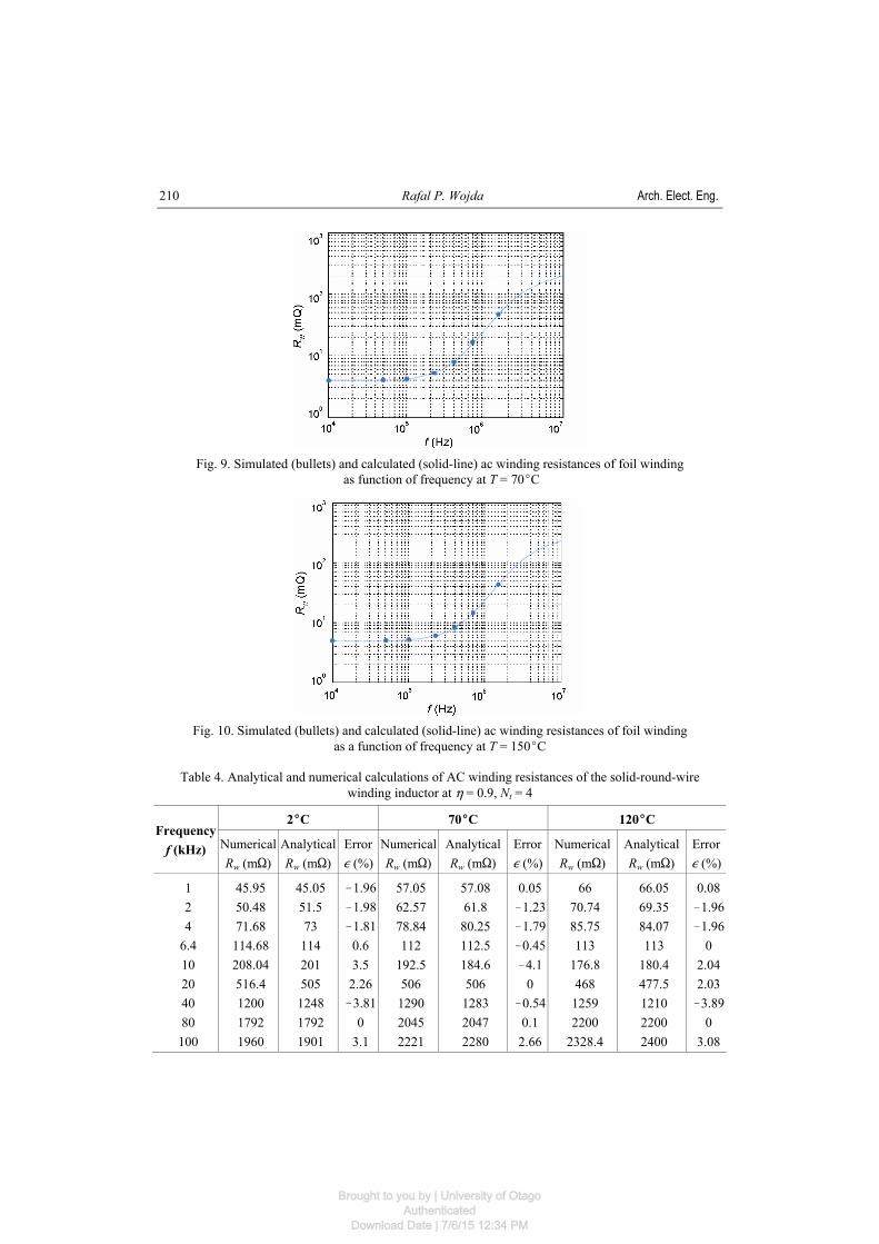
Table 1 lists parameters of the modeled inductors. The designed inductors are based on the Magnetics Inc. 0R42616 ferrite ungapped pot core. The ungapped core was selected in order to eliminate the influence of the induced eddy currents in the winding from the air gap fringing flux. The initial permeability of the core material is μr = 2300, the mean turn length (MTL) is lT = 5.3 cm, and the breadth of the bobbin is bb = 11 mm. Simulations have been performed at different conductor temperatures using Maxwell 3D eddy current solver at selected frequencies. Table 2 lists analytical and numerical calculations of the ac winding resistances as well as relative errors at temperatures T = 0, 70, 150EC for foil winding inductor. The analytical and numerical calculations are also showed in Figures 8-10, where the solid line represents the analytical predictions of ac winding resistance (calculated from Dowell’s equation) and bullets represents numerical predictions of the ac winding resistance (obtained from the FEM eddy-current analysis). It can be seen that the analytical calculations of ac winding resistance for the foil winding tracks the numerical calculations of ac winding resistance with high accuracy. Moreover, it can be seen that above certain frequency, the ac winding resistance of the foil at T = 0EC is higher than for the foil at T = 70 and 150EC. This cause excessive power loss in the winding and excessive temperature rise of the inductor. Therefore, it is substantial to take into account the influence of the temperature in designing process of the inductor windings. Note that for the foil winding Dowell’s equation at T = 0EC overestimates the numerical ac winding resistance on average by 3.6% and maximum by 12.6%. At T = 70EC, Dowell’s equation over-estimates the numerical ac winding resistance on average by 0.2% and maximum by 1.41%. On average at T = 150EC, Dowell’s equation underestimates ac winding resistance by 0.06%. Tables 3 and 4 list the analytical and numerical calculations of the ac winding resistances for the solid-round-wire windings at temperatures T = 2, 70, 150EC for two- and four-layer winding inductors, respectively. Note that for both inductors calculations of solid-round-wire winding ac resistances are similar. Though Dowell’s equation disregards curvature, end, and edge effects, for solid-round-wire windings it underestimates the simulated ac winding resis-tance on average by 0.9%. Moreover, calculated winding resistances at the local minimum are also similar to the simulated values. This proves that analytical Equations (17), (26), and (34) are a very good and ease to use equations for first step of inductor winding design process.
Fig. 7. 3D Model of the two layer solid-round-wire winding inductor
Brought to you by | University of OtagoAuthenticated
Download Date | 7/6/15 12:34 PM

Vol. 64 (2015) Thermal analytical winding size optimization for different conductor shapes
209
Table 2. Analytical and numerical calculations of AC winding resistances of the four-layer foil winding inductor
0EC 70EC 150EC Frequency f (kHz) Numerical
Rw (mS) Analytical Rw (mS)
Error , (%)
NumericalRw (mS)
Analytical Rw (mS)
Error , (%)
Numerical Rw (mS)
Analytical Rw (mS)
Error , (%)
11 50
100 225 400 700 1500
3.065 3.15 3.39 4.175 8.69 176.6 512
3.2 3.2 3.6 4.7 8.4 180 530
4.4 1.59 6.19 12.57!3.341.93 1.73
3.978 4.04 4.231 5.255 7.945 163.7 473.6
3.99 4.05 4.2 5.24 7.98 166 474
0.3 0.25 !0.73!0.290.44 1.41 0.08
5.022 5.069 5.222 6.036 8.234 144.6 428.9
5.02 5.06 5.22
6.038 8.25
144.7 427
!0.04 !0.18 !0.04 0.03 0.19 0.07 !0.44
Fig. 8. Simulated (bullets) and calculated (solid-line) ac winding resistances of foil winding
as function of frequency at T = 0EC
Table 3. Analytical and numerical calculations of AC winding resistances of the solid-round-wire winding inductor at 0 = 0.9, Nt = 2
2EC 70EC 120EC Frequency f (kHz) Numerical
Rw (mS) Analytical Rw (mS)
Error , (%)
NumericalRw (mS)
Analytical Rw (mS)
Error , (%)
Numerical Rw (mS)
Analytical Rw (mS)
Error , (%)
1 2 4 10
13.5 20 40 80
100
21.18 22.98 25.56 44.17 56.34 83.12 156 247 291
21.84 22.47 25.06 42.88 56.18 86.97 162.7 240.3 264.5
3.12 !2.22!1.96!2.92!0.284.63 4.29 !2.71!9.11
27.2 29.1 31.1 46
55.7 81.2 179 283 311
28.1 28.53 30.5 44.3 55.4 82.8 171.3 273.8 305.3
3.31 !1.96!1.93!3.7!0.541.97 !4.3!3.25!1.83
32.56 33.65 39.9 48.6 58 86 177 294
343.3
32.56 33.01 34.76 46.34 58.06 83.16 175.1 297.1 331.1
0 !1.9 !12.88 !4.65
0.1 !3.3 !1.07 1.05 !3.55
Brought to you by | University of OtagoAuthenticated
Download Date | 7/6/15 12:34 PM
Rafal P. Wojda Arch. Elect. Eng.
210
Fig. 9. Simulated (bullets) and calculated (solid-line) ac winding resistances of foil winding
as function of frequency at T = 70EC
Fig. 10. Simulated (bullets) and calculated (solid-line) ac winding resistances of foil winding
as a function of frequency at T = 150EC
Table 4. Analytical and numerical calculations of AC winding resistances of the solid-round-wire winding inductor at 0 = 0.9, Nt = 4
2EC 70EC 120EC Frequency f (kHz) Numerical
Rw (mS) Analytical Rw (mS)
Error , (%)
NumericalRw (mS)
Analytical Rw (mS)
Error , (%)
Numerical Rw (mS)
Analytical Rw (mS)
Error , (%)
1 2 4
6.4 10 20 40 80
100
45.95 50.48 71.68
114.68 208.04 516.4 1200 1792 1960
45.05 51.5 73
114 201 505 1248 1792 1901
!1.96!1.98!1.81
0.6 3.5
2.26 !3.81
0 3.1
57.05 62.57 78.84 112
192.5 506 1290 2045 2221
57.08 61.8
80.25 112.5 184.6 506
1283 2047 2280
0.05 !1.23!1.79!0.45!4.1
0 !0.54
0.1 2.66
66 70.74 85.75 113
176.8 468 1259 2200
2328.4
66.05 69.35 84.07 113
180.4 477.5 1210 2200 2400
0.08 !1.96 !1.96
0 2.04 2.03 !3.89
0 3.08
Brought to you by | University of OtagoAuthenticated
Download Date | 7/6/15 12:34 PM

Vol. 64 (2015) Thermal analytical winding size optimization for different conductor shapes
211
7. Conclusion
There are many publications considering analytical optimization of the winding conductor size for the conductor temperature equal to room temperature [10, 16-19]. However, com-mercially available power devices, i.e. converters, power amplifiers, rectifiers, filtering and matching circuits operates at temperatures much higher than the room temperature, and there-fore, optimization of the winding conductor taking into consideration thermal effect is crucial in these devices design process. Current literature lacks an analytical optimization of the wind-ing conductor including thermal effects. In this paper, thermal analytical optimization of the winding conductor sizes, thickness and diameter, have been performed. Main advantage of derived equations is that they are easy to implement in the design process of the winding con-ductors conducting sinusoidal currents. Temperature dependent 1D ac winding resistance of the inductor winding has been derived and approximated. Moreover, the conductor temperature dependent analytical optimization of the foil winding thickness has been performed as well as temperature dependent valley thick-ness and diameter of the square-wire and solid-round-wire winding have been derived. The derived equations for the optimum foil thickness and valley diameter of the solid-round-wire windings have been validated by the 3D FEM simulations. The simulations showed that the temperature dependent ac winding resistance calculated from Dowell’s equation tracks the FEM results with high accuracy. Moreover, it has been shown that the equations for the optimum foil thickness (17) and the optimum diameter of the solid-round-wire windings (34) are a very good designing tool for windings operating at different temperatures. The following conclusions can be drawn from the analysis of this paper: $ For the foil winding, the ac resistance at the global minimum is temperature dependent and
it increases as temperature increase;
Fig. 11. Simulated (bullets) and calculated (solid-line) ac winding resistances
of the four-layer solid-round-wire winding inductor as a function of frequency at T = 2oC $ As the temperature increases the optimum foil thickens increases non-linearly. $ For the foil winding inductors, Dowell’s equation overestimates the winding resistance on
average by 1.23%.
Brought to you by | University of OtagoAuthenticated
Download Date | 7/6/15 12:34 PM

Rafal P. Wojda Arch. Elect. Eng.
212
Fig. 12. Simulated (bullets) and calculated (solid-line) ac winding resistances
of the four-layer solid-round-wire winding inductor as a function of frequency at T = 70EC
Fig. 13. Simulated (bullets) and calculated (solid-line) ac winding resistances
of the four-layer solid-round-wire winding inductor as a function of frequency at T = 120EC $ For the square-wire and solid-round-wire windings, the ac resistance at the local minimum
is independent on temperature. $ As the temperature increases, the valley thickness and valley diameter increases non-
linearly. $ For the solid-round-wire winding inductors, Dowell’s equation underestimates the winding
resistance on average by 0.9%. References [1] Kazimierczuk M.K., RF Power Amplifiers. John Wiley & Sons, Chichester, UK (2008). [2] Kazimierczuk M.K., Czarkowski D., Resonant Power Converters. 2nd ed. IEEE Press/John Wiley
& Sons, New York, NY (2011). [3] Kazimierczuk M.K., Puleswidth Modulated DC-DC power converters. John Wiley & Sons, Chi-
chester, UK (2009).
Brought to you by | University of OtagoAuthenticated
Download Date | 7/6/15 12:34 PM

Vol. 64 (2015) Thermal analytical winding size optimization for different conductor shapes
213
[4] Yu Q., Holmes T.W., Naishadham K., RF equivalent circuit modeling of ferrite core inductors and characterization of core materials. IEEE Trans. Electromagn. Compat. 44(1): 258-262 (2002).
[5] Huang R.F., Zhang D.M., Tseng K.-J., Determination of dimension independent magnetic and dielectric properties for MnZn ferrite cores and its EMI applications. IEEE Trans. Electromagn. Compat. 50(3): 597-602 (2008).
[6] Naishadham K., Closed-form design formulas for the equivalent circuit characterization of ferrite inductors. IEEE Trans. Electromagnet. Compat. 53(4): 923-932 (2011).
[7] Wrobel R., Mellor P.H., Thermal design of a high-energy-density wound components. IEEE Trans. Ind. Electron. 58(9): 4096-4104 (2010).
[8] Wrobel R., Mlot A., Mellor P.H., Contribution of end-winding proximity losses to temperature variation in electromagnetic devices. IEEE Trans. Ind. Electron. 59(2): 848-857 (2011).
[9] Dowell P.L., Effects of eddy currents in transformer winding. Proc. IEE 113(8): 1387-1394 (1966). [10] Snelling E.C., Soft Ferrites, Properties and Applications. 2nd ed. London, U.K.:Butterworth (1988). [11] Kutkut N.H., A simple technique to evaluate winding losses including two-dimensional edge effect.
IEEE Applied Power Electronics Conference, Atlanta, Feb. 1997. [12] Kutkut N.H., Divan D.M., Optimal air-gap design in high-frequency foil windings. IEEE Applied
Power Electronic Conference, Atlanta (1997). [13] Bartoli M., Reatti A., Kazimierczuk M.K., Modelling iron-powder inductors at high frequencies.
IEEE Industry Applications Society Annual Meeting, pp. 1225-1232 (1994). [14] Murthy-Bellur D., Kazimierczuk M.K., Harmonic winding loss in buck DC-DC converter for
discontinuous conduction mode. IET, Power Electron. 3(5): 740-754 (2010). [15] Kondrath N., Kazimierczuk M.K., Inductor winding loss owing to skin and proximity effects
including harmonics in non-isolated pulse-width modulated dc-dc converters operating in continuous conduction mode. IET, Power Electron. 3(6): 989-1000 (2010).
[16] Kazimierczuk M.K., High-Frequency Magnetic Components. John Wiley & Sons, Chichester, UK (2014).
[17] Wojda R.P., Kazimierczuk M.K., Winding resistance of litz-wire and multi-strand inductors. IET, Power Electron. 5(2): 257-268 (2012).
[18] Wojda R.P., Kazimierczuk M.K., Analytical optimization of solid-round-wire windings. IEEE Trans. Ind. Electron. 60(3): 1033 - 1041, 2013.
[19] Wojda R.P., Kazimierczuk M.K., Magnetic field distribution and analytical optimization of foil windings conducting sinusoidal current. IEEE Magnetics Letters 4 (2013).
[20] Koteras D., Calculation of eddy current losses using the electrodynamic similarity laws. Archives of Electrical Engineering 63(1): 107-114 (2014).
[21] Budnik K., Machczynski W., Magnetic field of complex helical conductors. Archives of Electrical Engineering 62(4): 533-540 (2013).
[22] Strouboulis T., Zhang L., Babuska I., Assessment of the cost and accuracy of the generalized FEM. International Journal for Numerical Methods in Engineering 69(2): 250-283 (2007).
[23] Gradzki P.M., Jovanovic M.M., Lee F.C., Computer-aided design for high-frequency power transformer. Annual Applied Power Electronics Conference and Exposition, Los Angeles, CA, USA, 1990, pp. 336-343. (1989).
[24] Lotfi A.W., Gradzki P.M., Lee F.C., Proximity effects in coils for high frequency power applications. IEEE Trans. Magn. 28(5): 2169-2171 (1992).
[25] Cheng K.W.E., Evans P.D., Calculation of winding losses in high frequency toroidal inductors using single strand conductors. IEE Electr. Power Appl. 141(2): 52-62 (1994).
[26] Cheng K.W.E., Evans P.D., Calculation of winding losses in high frequency toroidal inductors using multi-strand conductors. IEE Electr. Power Appl. 142(5): 313-322 (1995).
[27] Robert F., Mathys P., Schauwers J-P., Ohmic losses calculation in SMPS transformers numerical study of Dowells approach accuracy. IEEE Trans. Magn. 34(4): 1255-1257 (1998).
[28] Pernia A.M., Nuno F., Lopera J.M., 1D/2D transforer electric model for simulation in power converters. 26th Annual IEEE Power Electronics Specialists Conf., Atlanta, GA, USA, June 1995, vol. 2, pp. 1043-1049 (1995).
Brought to you by | University of OtagoAuthenticated
Download Date | 7/6/15 12:34 PM
Rafal P. Wojda Arch. Elect. Eng.
214
[29] Ayachit A., Kazimierczuk M.K., Thermal effects on inductor winding resistance at high frequen-cies. IEEE Magnetic Letters 4 (2013).
[30] de Gersem H., Hameyer K., A finite element model for foil winding simulation. IEEE Transactions on Magnetics 37(5): 3427-3432 (2001).
[31] Wojda R.P., Kazimierczuk M.K., Analytical winding foil thickness optimisation of inductors conducting harmonic currents. IET Power Electronics 6(5): 963 973 (2013).
[32] Wojda R.P. Kazimierczuk M.K., Analytical winding size optimisation for different conductor shapes using Ampre’s Law. IET Power Electronics 6(6): 1058-1068 (2013).
[33] Wojda R.P., Kazimierczuk M.K., Analytical optimisation of solid-round-wire windings conducting dc and ac non-sinusoidal periodic currents. IET Power Electronics 6(7): 1462-1474 (2013).
[34] Wojda R.P., Kazimierczuk M.K., Optimum foil thickness of inductors conducting DC and non-sinusoidal periodic currents. IET Power Electronics 5(6): 801-812 (2012).
[35] Wojda R.P., Kazimierczuk M.K., Proximity-effect winding loss in different conductors using magnetic field averaging. COMPEL:The International Journal for Computation and Mathematics in Electrical and Electronic Engineering.
[36] Kazimierczuk M.K., Wojda R.P., Foil winding resistance and power loss in individual layers of inductors. Int. J. Electron. Telecommun. 56(3): 237-246 (2010).
Brought to you by | University of OtagoAuthenticated
Download Date | 7/6/15 12:34 PM