Theoretical Estimation of the Influence of Some Main ... · Subscrlpt denoting rudder. Lateral if...
27
da'4J FL;i]:-. i'1,J. (n OF Tii:i 1.i.5.M.8. 77 THE SOCIETY OF NAVALARCHITECTS AND MARINE ENGINEERS OneWorld Trade Center. Suite1369, NewYork, N.Y. 10048 Papsr to be p.esenled al thsChesaPeake Sailing Yacnt Synposium. annapolis Maryland' J anuary 20. 1979. d F Fll f G cz g H h I J KG I{M k Gireh difference Parameter ' Subscripts denoting entrance. Force, freeboard, subscriPt denoting "frictional". Lateral force of sail. Freeboard to foot of mast. Froude nun rer. Driving: force of sails. Subscript denoting fore-body. Girth, subscrj-pt denotinq center of gravrt'y. Righting ann. Acceleration due to gravity. Height. subscript denoting hull. vertical hetght of section of hull-' Height of foretriangl'e, subscript denoting "induced". galf angle of entrance of load wa- terline, Base of foretriangle. Height of center of gravity above bottom of keel Height of transverse rnetacenter above bottom of keel. Subscript denoting kee1. form fac- tor in frictlonal resistance formu- lation. Subscript denoting combined keel and trimtab configuration. Length. Rated hull length. Longitudinal center of buoyancy. Length of run. Dimensionless waterline length. Mass. rnonent. Hdight of maj-nsail boom above foot of mast, Subscript denoting midship ' subscrlpt denoting maxirnum. Subscript denoting minimum. subscript denotinq over-all. Subscript denoting Profile of entrance. Subscript dehoting profile of run. Subscripls denoting run ' Reynolds number. Subscrlpt denoting rudder. Lateral if ind resistance force. subscript denoting heeled residuary resis tance. Rated sail area, wetteil surface skin girth. geight of spinnaker. AR bv, CE C!,rp ktt L Lt I,CB Lrun 1!, M MSBH m nax man oa pr Rrr Rn RUD RI4r, s Theoretical Estimation of theInfluence of Some Main Design Factors on thePerformance of International Twelve Meter Class Yachts Petervan Oossanen, Visiior, Netherlands Ship Model Basin, Wageningen, TheNetherlands ABSTRACT A theoretical study is carried out to determine the influence on per- fcrnance of some main d.esign factors of International Tivelve Meter Class Yachts, such as length, sail area, beam, alraft and stability. This is realized by de- siqning a serj,es of Twelve Meter Yachts in which the length, sail area, beam, draft and the position of the vertlcal center of gravity are systematica.Lly varied. For the design of the canoe body. a mathematical procedule is used. The yachts of this series are each analyzed with respect co the various polnts of sailing. on cornparing boat speed, speed made good to lrindward, heel and leeway angles for the different yachts for various true wincl speeds, a number of conclusions are reached on the optimum values of the design factors lnvestj-gated. A main result of the study is that the most important question to be answereil in designing a Twelve Meter is whether the yacht must perform best in the close- hauled condition in true wind speeds in excess of about 15 knots, or whether the yacht must perform best in wind speeds not exceealing 15 knots, ln r^'hich case no differentiation is necessary between the different points of sailing. NOMNNCLATURE Projected area, holst of mainsail, sail area. Aspect ratio. Subscript denoting aft-body. subscript denotj.ng apparent ilrind. Bean or breadth, foot of mainsail, subscript denoting boat. Span of liftinq surface. Dimensionfess breadth of rraterline. Block coefficient. Center of effort of sail. Friction coefficient. chain girth. T,ift coefficient. Prismatic coeff icient. coefficient of half angle of entrance of waterline. waterplane coeff icient. subscript denoting canoe body, chord- len.rth of liftinq surface.
-
Upload
vuongkhanh -
Category
Documents
-
view
219 -
download
1
Transcript of Theoretical Estimation of the Influence of Some Main ... · Subscrlpt denoting rudder. Lateral if...
da'4JFL;i]:-. i'1,J. (n
OF Tii:i 1.i.5.M.8.
77
THE SOCIETY OF NAVAL ARCHITECTS AND MARINE ENGINEERSOne World Trade Center. Suite 1369, New York, N.Y. 10048
Papsr to be p.esenled al thsChesaPeake Sailing Yacnt Synposium. annapolis Maryland' J anuary 20. 1979.
d
F
Fll
fG
czgHh
I
JKG
I{M
k
G i reh d i f f e rence Pa rame te r 'Subscripts denoting entrance.Force, freeboard, subscriPtdeno t i ng " f r i c t i ona l " .
La te ra l f o r ce o f sa i l .Freeboard to foot of mast.Froude nun rer.Driving: force of sai ls.Subscript denoting fore-body.Girth, subscrj-pt denotinq center ofgravrt 'y.Righting ann.Accelerat ion due to gravity.He igh t .subscript denoting hul l . vert icalhetght of section of hul l- 'He igh t o f f o re t r i ang l ' e , subsc r i p tdeno t i ng " i nduced " .galf angle of entrance of load wa-te r l i ne ,Base o f f o re t r i ang le .Height of center of gravity abovebottom of keelHeight of transverse rnetacenterabove bottom of keel.Subscript denoting kee1. form fac-tor in fr ict lonal resistance formu-l a t i on .Subscript denoting combined keeland tr imtab configuration.Length.Rated hul l length.Longitudinal center of buoyancy.Length of run.Dimensionless waterl ine length.Mass. rnonent.Hdight of maj-nsai l boom above footo f mas t ,Subscript denoting midship 'subscrlpt denoting maxirnum.Subscript denoting minimum.subsc r i p t deno t i nq ove r -a l l .Subscript denoting Profi le ofen t rance .Subscript dehoting profi le of run.Subscripls denoting run 'Reynolds number.Subscrlpt denoting rudder.Lateral i f ind resistance force.subscript denoting heeled residuaryres i s t ance .Rated sai l area, wettei l surface
sk in g i r t h .geight of spinnaker.
AR
bv,
CE
C!,rp
ktt
LL tI,CBLrun1!,MMSBH
mnaxmanoa
prR r rRnRUDRI4r,
s
Theoretical Estimation of the Influence of Some MainDesign Factors on the Performance of InternationalTwelve Meter Class YachtsPetervan Oossanen, Vis i ior , Nether lands Ship Model Basin, Wageningen, The Nether lands
ABSTRACT
A theo re t i ca l s t udy i s ca r r i edout to determine the inf luence on per-fcrnance of some main d.esign factors ofInternational Tivelve Meter Class Yachts,such as l eng th , sa i l a rea , beam, a l r a f tand s tab i l i t y . Th i s i s r ea l i zed by de -siqning a serj ,es of Twelve Meter Yachtsi n wh i ch t he l eng th , sa i l a rea , beam,draft and the posit ion of the vert lcalcenter of gravity are systematica.Llyvaried. For the design of the canoe body.a mathematical procedule is used. Theyachts of this series are each analyzedw i th respec t co t he va r i ous po ln t s o fsai l ing. on cornparing boat speed, speedmade good to lr indward, heel and leewayangles for the dif ferent yachts forvarious true wincl speeds, a number ofconclusions are reached on the optimumvalues of the design factors lnvestj-gated.A main result of the study is that themost important question to be answerei lin designing a Twelve Meter is whetherthe yacht must perform best in the close-hauled condit ion in true wind speeds inexcess of about 15 knots, or whether theyacht must perform best in wind speedsnot exceealing 15 knots, ln r^ 'hich case nodifferentiat ion is necessary between thed i f f e ren t po in t s o f sa i l i ng .
NOMNNCLATURE
Pro jec ted a rea , ho l s t o f ma insa i l ,sa i l a rea .Aspect rat io.Subscript denoting aft-body.subscript denotj .ng apparent i l r ind.Bean o r b read th , f oo t o f ma insa i l ,subscript denoting boat.Span o f l i f t i nq su r face .Dimensionfess breadth of rraterl ine.B lock coe f f i c i en t .Cen te r o f e f f o r t o f sa i l .F r i c t i on coe f f i c i en t .chain girth.T,i f t coeff icient.P r i sma t i c coe f f i c i en t .coeff icient of half angle ofentrance of waterl ine.waterplane coeff icient.subscript denoting canoe body, chord-len.rth of l i f t inq surface.
vVrnq
w?
vr1
78
SPBH geight of splnnaker boon abovefoot of mast.
sk subscrlpt denoting skeg.sr subscript denoting combj.netl skeg
and rudder configuration.T Draft. subscrlpt denotj-ng transom.t D imens ion less dra f t , subscr iP t
denoting transom.tt Subscript denotj.ng trimtab.tw Subscrlpt denotlng true wind.t/c Thickness-chord length ratio of
I i € + i h d c t r r f a ^ a
ve loc i ty .speed made good to wlndward.Subscript denoting waterline 'subscript denoting waterplane.Subscrj-pt denoting wlnd (atr) .Subscript denotlng waterline 'dlnensionless vraterltne length.lenqth coordinace.oimensional breadth coordinate.Vertlcal- distance from load water-1 ine .
z Depth coordinate.B leeway angle.Btw Optinum heading angle relative to
tlue r,t ind dlrection.A Dlsplacenent of hulI.V voh]me of displacement.e Drag-lift ratio of saifs or
1 i F + i n d c l r r € ^ ^ a
L Dimensionless depth coordinate 'n Dimensionless breadth coorcl inate.I Taper rat io of l i f t ing surface.lc
Sweepback angle of quarter-chordl i ne o f l l f t i nq su r face .
Ag svieepback angl! of hinge l ine oftr lmtab or rudder.
v Kinenatic viscos i ty.q D imens ion less l eng thcoo rd ina te .p Fluid density.rm Half angle of trait ing edge of
^ cross-sectlon of l l f t ing surface.
0 Heel angle.
1. INTRODUCNION
since 1958, races between TnrelveMeter class Yachts for the AmericarsCup have general ly resulted in veryclose f inishes. With the exceplion oft he two B l i t l sh cha l f enges i n 1958 and1964 [ r ] r ) , t he d i f f e rence be tween Lheaverage speed of conpeling yachts overthe Americars Cup course has usua.Llybeen less than 0.1 knot ' Sett ing asidethose cases r1'hen racing tact ics requireyachts to remain in ctose vicinity(thereby f inishing cfose together), thisfact leads to the concl-usion that thed i f f e rences i n t he ove ra l l sa i l l ngperformance between Tlrelve Meter Yachtslre small . Recentl-y, this fact has 1edsome to bel j-eve that this type of yachL
can no longer be irnproved upon and lhatan optlmum size and forn has been reachedwithin the constraincs imposed by theTwelve I ' teter Rating RuIe. This poinL ofview is indeed supported by the factthat in the very fe!,r cases in which adesigner has attemPted to signif icantlydepart from contemporary Practice withrespec t Eo t he cho i ce o f ma ln des ignparirneters (HERITAGE in 1970 [1] andi. lAnrwsn ln 1974 12) ) ' rath?F disappoint-inq results were obtained z/. As a con-se {uence , i t i s d i f f l cu l t t o j us t i f y
or prove t l ' le clairn that the design ofTwelve Meters can be inproved. Yetamongst those who adhere to lhis bel lefcan be found some prominent naval archi-tects and yacht designers, Part icularlythose who are, or have been, engaged inTwelve Meter design. A general conten-t ion of this group is, hovtever, that i tw i l l r equ i re cons ide rab le sys tema t i cresearch to real ize a new Twelve l{eterYacht with signl-f icantly improved per-fornance.
The nain air of the study on whichthis paper is based was to f ind someevidence in support of the claln thatpresent-day Twelve Meters can be lm-proved by choosinq another trade-offbetlreen 1ength and sai l area, beam anddraft. etc. The trade-off between water-I ine lengLh and sai l area is probabl-ythe nos ! lmpo r tan t l n t h i s r esPecLsince both the minimum displacement andthe maximum draft ( to botton of keel)are f lxed once lhe rraterl ine length lsse lec ted .
Numbers in brackets designate refer-ences l isted at the end of thls paper.
The successful design and conceptiono f INTRIPTD in 1967 l 3 l i s no t i n -conslstent with this
-s€atement since
the success of this Twelve Meterwas not due to a new trade-off be-tween the main design Paraneterssuch as l enqLh and sa i l - a rea , bu tto a breaktf irough In the deslgn ofkeel and rudder.
x
z
r )
2 )
In defining a procealure for deter-nining the optimrm values of the maindesign factors for Twelve Meter Yachts,two dif ferent apploaches can be adopted.The f irst anal most desirable of theseconsists of carrying out extensivetests, in snooth and rough water, witha large number of scafed nodels tos tudy t he e f f ec t o f l eng th , d i sp lace -menL, beam, draft and stabi l i ty onhydrodynamic drag and side folce forvarious forward speeds. leeway (yaw) andheel angles. On assuming a set of valuesfor the saj. l dr iving and sai l heel ingforces for various wind velocit ies andcourse angles, the result ing boat speed.s,Iee!,ray and heel angles can be deter-mined for the running, reachlng andclose-hauled condit ions. This approach.ho\a/ever, is very expensive and time-consumlng due to the large number of - ,models ani l test pararneters involved l l .
A second, perbaps more practicalapproach for a part icular design. is tocarry out a systematic series of calcu-lat ions to determine the inf luence ofthe main design factors on speed,leeway anal heef, for various true windvelocit ies and boat headings. I f thedevelopnent of the theoretical nod.elfor these calculat ions is careful lyexecuteal, the results should at leastbe quali tat ively correct. This wasrecJntly demonstrated by r ' lyers [5]Analyses of the resufts of these cal-culat ions vri l l lead to val i .d conclusionsvri th respect to \^ 'hich values of themain design parameters are most desir-able for optimum performance, for aspec i f i c po in t o f sa i l i ng . The t es t i ngof only a sma11 series of models, cen-tereal arounil the theoretical ly deter-mined optimum, is then needeal to checkthe calculat ions and to obtain accurateful l-scafe predict ions.
In this paper, a theoretical modelfor the cal-culat ion of the sai l ing per-formance of yachts is adopted to sys-tenatical- ly deterrnine the inf luence ofIength. displacement, canoe body draft,beam on the waterl ine and stabi l i ty onthe running, reaching and close-hauledperformance for various tarind speeds.It forrns part of the required study tocarry out the second type of optimi-zation program alescribed. above, Theresults sho\,r that the most inportantquestion to be ans\^rereal ln designinga T\{e1ve Meter is whether the yacht mustperform best in the close-hauled condi-t ion in true wind speeds in excess ofapproximately 15 knots or whether theyacht must perform best in wind speedsnot exceedinq 15 knots, l-n whiqh caseno dif ferentiat ion is necessary betnreendifferent points of sai l ing.
79
In this paper only the smooth uraterperformance is considered. For thisreason the glven results should be con-sidered tentat ive unti l the resul-ts ofsystenatic tests or calculat ions forthls type of yacht become avai lable.
2. THE INTERNATIONAL TWELVE METER CLASSRATING RUIE
The International Tvelve MeterClass Ratlng RuIe requires that thefol lowing explession is satisf ied:
L + 2 d . - F + r ' S _ r r r2 . 3 1
w h e r e L = L . + I . 5 ( 2 G - - L 2 \ + l ? G - 2 h \ / 1l !
( 2 )
i n wh i ch :L, = length of the hul l along' a watet-
' l ine 180 mm above the load r\ta!er-l i n e ( s e e F i g I ) ;
c r = g i r t h o f one -ha l f o f t he bo l r sec --
t i on l oca ted a t t he f o re -end ing o f| } t a T - L r r ' l l l a h ^ F l t + ^ - h ^ i h +
780 run above the load water.Line( s e e F i q . r ) . I n c a l c u l a t i n g L I ,t h e v a l u e o f I . 5 ( 2 G f - 1 . 2 ) n a y n o tbe l - ess t han 0 .36 me te rs ;
c = o i r t h o f . l nF -h^ l f o f t he s te rn*
section located at the aft-endingof the Lr hul l lenqth to the decka t t he s i de ( see r i q . L ) . I n ca l -
' ' ? o fs u r d L r r l 9 ! t L r r e v d r u .
l2ca-2ha) /3 may not be less Lhan1 . . 2 m e t e r s ;
h = v r r t i . a l h F i d h f o F f h e s e c t i o n a L*
t he a fL -end j . ng o f t he L l hu l ll a n d l - h : + r h a c i A A ^ f + h a r ' ^ . h +
Further,
. l - r / c c - . / : r ( 3 )
in which:SG* = s l i n g i r t h ( a l ong hu l l su r f ace )" '
fron a point 1500 mn beLow theload \^ 'aterl ine to the deck at theside, of one-half of the hulf att he sec t i on l oca ted 0 .55 Lw I f r omihp f d rF -pnd ind . r f f - he l oad waLe r -l i n e ( s e e F i g . I ) ;
cG- = s6 .1 t t g i r l h ( g i r t h a l ong hu l r ,"
bridging any ho.Llows in the hul lby a straight l ine) from a point1500 mm below the load waterl- ineto t he deck a t t he s i de , a l so a tt he sec t i on l oca ted ^rhe r^rc-an.r i n- .r ri""io#'"u1*t e r l i n e ( s e e F i g . I ) .
A1so,
r ' = ( F r , , - + F - + F T . , ) / 3 ( 4 )
in which:Fr.- -= freeboard at the fore-ending of-L t
the Lr hu l l leng th ;
l) For IOR type yachts, this approachis be_ing persued by cerritsria eta 1 I 4 l .
80
F- = freeboard at the girth stat ion 1o-" '
cated 0.55 l4^'1 from the fore-ending of the load waterl inei
Fr- = freeboard at the aft-ending of" l t
th. Lr hul l length (Ftr1 - is equalt o h a + 0 . 1 8 m e t e r s ) .
^ -
The value of F for use in the RatingFormuLa (r) may not exceed 1.21 meters.In addit ion
F , < 0 . 8 2 5 F ," la - " l f
and
1 . 2 F - < F . < 1 . 5 F *n ' - l l f
The sheer is to be a fair qoncave curve.F ina I ly ,
^ A x B 0 . 8 5 I x Jn = - z - - - - - - - - z -
ln ithich:A = heisht (hoist) of triangular main-
sail from toP of boom ln meters.The top of the mainsall may notexceeal a height equal to 25 metersneasured fron a Polnt 180 run abovethe deck at the siale' abreast ofthe mast;
B = foot of triangular mainsail in
I = helght (hoist) of genoa measurealfrorn a point 180 mn above the deckat the slde at the fore-si-de of themast. This height may not exceed1 8 . 7 5 m e t e r s ;
J = foot of genoa from the fore-side ofthe nast to the aft-side of thefore-stay. The genoa may not extenalmore than 4.8 meters behind thefore-side of the mast.
In effect, the above Rating Ruleis relatively simple cornpared to thernternational offshore Rule (IoR). forexanple. In additj-on to this RuLe.howeirer, the International Yacht RaclngUnion (IYRU) has adopted many Linita-tions on other dl.nensions since the rulewas tlevLsed in 1906. The most importantof these are the follolt ing:- The maximum draft pernltted is thataccording to the formuLa:
T = 0 . 1 6 1 - - , + 0 . 5 ( 6 )max
in $rhich Tmax is the maximum draft tobottom of lieel in tneters ' and L\irl isthe rraterlLne length in meters' If thedraft exceetts Trna:<, lhree tines theexcess is to be added to the left-handslde of the Rating fornula (l).- The minlnum dlsplacenent perrd-ttedis Lhe value following from the formula:
f l = t n , r . * n - r s ) 3 l ' r ' )v m i n - \ v . . ! w 1 w . r J ,
ln which V-ih is the minimum displace-ment in cuEid meters and LwI is thewaterl ine length in meters. I f the dis-placement is less than requl-red byio rmu la (? ) , t he de f i c i ency i n wa te r -Ltne l-ength corresponaling to the actuaL
stenn section section ot O.55 Lwlg lrom forword'. perpendiculor bow sectjon
o t L1 f
lengths ore in mm
ot Llo
oxis ofruooer
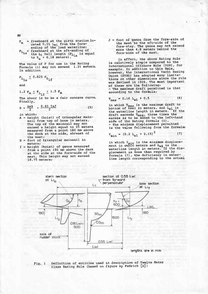
Definit ion of entl t ies used in descript ion of Tw-e1ve Meter
class Rattng Rule (based on f igure by Pedrick L6l )! l g . r

displacement is doubled and addetl to theteft-hand-side of the rat inq fornula (1).- The minimum beam, measured at a heighto f one - th i r d t he f r eeboa rd , a t t he 10 -cation of maxinum beam. may not be lessthan 3 .6 ne te rs . Any de f i c i ency i s t obe mult ipl ied by 4 and added to r, asdefined 1!l formula (2) .- The afterbody of the yacht mustbe so shaped Lha t t he g i r i : h d i f f e rence ,defined in the same way as Lhe girLhdifference of the section at theaft-ending of the LI hul1 length,of the section at the location ofthe intersection of the slern prof i leand the waterl ine located 360 mmabove the l oad i va te r l i ne , i s ] a rge rt r han 65 pe r cen t o f t he s te rn g i r t hd i i f e rence a t Lhe L r hu l l - l eng thend ing . I n add l t i on ; t he l oca t i ono f t h i s sec t i on mav no t be-Less than 380 nun aft of the section atthe LI hul1-length ending.- Furthermore, no hol lorats are permittedin the surface of the hul l between theload waterl ine and the sheer l ine' ex-cept in a very 1oca1 area near the aft-end of the vraterl i .ne.
Other l ini lat ions are placeal on thesize of spinnakers, headboards, battens,deck-openings, equipment on board, mastal imensions, booms, the number of personson board during a race, the use of lareand expens i ve rna te r i a l s e t c . , a l l o frrhlch are described in the Tvrelve MeterRatinq Rule and Measurenent Instruct ionsassueo Dy l ne r rRU L / l ,
Due to the rather severe restr ic-t ion set on displacement, maxinum draftanal ninimum beam, the hu1l forn ofTwelve }teter Yachts tend to look moreal ike than do yachts designed accordingto the International Offshore Rule.This is an indication that, even thoughthe Twelve Meter RaLing RuIe is relat i-vely simple, i t is also more severe.The prj-ncipal trade-off is that betweenlength and sai l area. canoe body draftis also inportant since this determlnesthe va lue o f 2d i n f o rmu la ( I ) . A sha l -low canoe body rr i l1 lead to a relat l-vely large 2d value.
3. DESIGN OF SYSTEMATIC SERIES OF TWELVEMETER YACHTS
3 .1 Des iqn o f Canoe Bodv
To fac i l i t a te t he sys tema t l c de -sign of a large number of Twelve MeterYachts according to the Rating Rule, adimensionless mathematical representa-tlon of the entire canoe body r,ras ale-veloped. For this purpose lhe canoebody is divided into 2 parts; the partforwaral of the maxirnum sectlon (thee.trance) and the part aft of the maxi-num section (the run). The naximrmsection is defined as the section withthe greatest breadth and greatest dlafLFor both entrance and run, the breadth
81
offset from the centerplane of the hull-is aleveloped as an analytical functionof length and depth ordinates. fn thisra'ay the breadth offset is defined forevery locatlon on the hulf surface'for the entrance' the analytical ex-pression for the local breadth is devel-opeal as a function of canoe body draft/n \ +ha f raah^er. l .at thp nost forwardpolnt of the huII (Fnax) , the length ofthe load waterl ine of the entrance(L,\,r le ) . the overal l length of the hu1lfoiward of the maximum sectLon (Loae) 'the breadth on the waterl ine of the max-imum section (e\^,f) , the extrapolatedbreadth of the huII at the maximum sec-t ion at a height above the load $rater-l ine corresponding to the valueF6ay (Bplns1) ' the maximum section coef-f icient (c6) ' the half angle of en-trance of the load waterl ine ( ie), andthe block coeff ici ,ent of the entrance(Cp - ) . Fo r t he run , t he ana l y t i ca l ex -p r6 i s i on f o r t he l oca l b read th o f f se tfrom the centerplane is developed asa functl-on of the enti t ies Ts, F141,B - r , B r ' * . * , de f i ned above , as we l l ast i i ; le;r ' . iEi i of the load waterl ine of therun ( r * . i - ) , The b fock coe f f i c i en t o ft he ru f f " ( cB . ) , t he ex t rapo la ted b read tho f t he t r ans6m ( i n a ve r t i ca l p l ane ) a ta height above the load lraterl ine equalt o F - - . (B4 ' ) , and t he he igh t o f t helowe'JE"point of Lhe transom above theLoad wa te r l i ne (HT) . A desc r i p t i on o fthe developnenE of the analyLical re-presentation of entrance ani l run isgiyen in Appendix l .
The values adopted for the aboveparameters in defining the systematicseries of Trrelve Meter Hulls are givenin Tab le I .
The maxinum freeboard (at the mostforward point of the hu1l) , Fmax, isdependent on the freeboard valuesF r . , - , F - and F r . . ( see equaL ion 4 ) and
the sheer l ine through these freeboardvalues. The sheer l- ine adopted for eachof the Twelve Meters comprising thesysternatic series is the curve vthj.ch canbe defined by f i t t ing a second degreepolynomial- through the values
F , = 1 . 3 7 m , F - = l . l 4 m a n d
F , = 1 . 1 2 r n .
The value of the maximum sectioncoeff icient was selected on the basisof keeping the prismatic coeff lcient oft he canoe body equa l t o 0 .55 , v i z :
uu = 6135 to/
\ ,rhere the block coeff iclent based onthe imrersed volume of the canoe boalyi s de f i ned as :
" = o '-Bc 1l '1. Blr l , Tc( e )
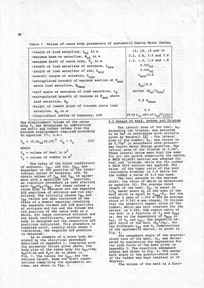
- length of loaal waterl ine' I ,wl in m
-maxinum beam on ltaterline, Bwl in m
-maxinum draft of canoe body' Tc in m
-Iength of load waterl lne of entrance, LwIe
-length of load waterl ine of run' Lwlr
-overal l length of entrance' Loae
-extrapolated breadth of maxlmum sectlon at Fmax
above load waterl ine. BFmax
-half angle of entrance of l-oad waterl ine' iE
-extrapolated breadth of transom at Fmax above
load waterl ine, BT
-height of lowest poj.nt of transom above load
waterl ine, l lT in m
-longitudlnal center of buoyancy' LCB
1 3 , 1 4 , 1 5 a n d 1 6
3 . 2 , 3 . 4 | 3 . 6 a n d 3
I . 2 , 1 , 4 t I . 6 a n d 1
0 .55r,w10 .45Lw1
L!tle'/o ' 8
Bwr/ o .9
arclan (Bw1/L!rIe)
" ' - -Fmax
0 . 6
23 of LwI afL af Lw!:2
8
8
a2
Table I Values of canoe body parameters of systenatic Twelve Meter Series
The displacenent volume of the canoebodv V- was determined by subtractingthe- ke;l- and rudder volume from themininum displacement required accoralingt o e q u a t i o n ( 7 ) ' t . e . :
r . , r ^ t 3 - n -. k v , ( r o )
rrhere1
vk = volume of keel in m- ,
Vr = volume of rudder in n-
The value of the block coeffLclento f en t rance . CD- , and run ' CRr , a redependent on tF- posit ion of-the longi-tudLnal center of buoyancy, LcB. Toobtain values of cEo and cRr in agree-nen t w i t h a spec i f iSd LCB
- -pos i t i on '
an i terat ion Procedure is used start j-ngwith CR.=CF-=CF^. For these values a
canoe 65dy-is d6signed and the separateLcB poslt ions of entrance and run cal-culaled. The init ial ly chosen cBe andCR. va.lues are then corrected on thelE-sis ot a moment equation involvingthe separate volumes and LCB posit ionsof entiance anal run and the volume andLcB posit ion of the canoe body as arrhole. For these correcteal entrance analrun block coeff icients, another canoebody is designetl and the respective LcBposit ions calculated. Th j-s procedure,lsiepeated untl l ' usual ly after about 5iterat ions, the required LCB posit ioni s ob ta ined .
As an example of a canoe body de-signed by the analyt ical proceduredescribed in Appendix 1, conplying l t i ththe parameter values given above, thebody plan of the canoe body for Lwt=I4m,Bwl=3.4rn and Tc=I .4m is sho'?tn inF iq . 3 . The va lues f o r cp - , f o r t hevai. ious lenqth, beam and-draft combi-nations comprising the systematic se-r i es , a re shown i n F ig . 2 .
3.2 Desiqn of Keel, Rudder and Trimtab
The lateral area of the keel ' Ak,lncludinq the tr imtab' '^ 'as selectedto be 5m2 in accordance tn' i th cr. i ter iaqiven bv Marshalt f8l The lateralirea of- lhe rudder, Ar, was chosen to
be O .75mz i n acco rdance w i t h p resen t -
day Twelve Meter design practice. fhelaierai- area of the t; intab is 0.6rn2.These lateral areas were kePt the same
for aI1 the yachts comprlsing the series'
A NACA 63,A015 section was adopted forkeel and
-tr imtab, rvhi le for the rudder
a NACA 0012 sectl-on was apPlied. Thevalue of the taPer rat io of the keel( includtnq tr imtab) is 0.6 ra'hi le forthe rudder a value of 0.4 was used.
The keel extends to the maxlmumdraft, the value of which is determinedbv equation (6) . The average chordt i nq€ t r o t t he kee l , E r . , i s equa l t os,/r i rneter where bk l 'd Lhe span of thekeel which is equal co TnAy-Tc. For therudde r a sDan o f L332 m-a i i d an ave ragecho rd o f 0 :563 n was chosen . r t f o l l owsthat the geometric aspect rat io of therudder" which was kept constant for these r i es , i s 2 .366 . I he aspec t r aL io o fthe keel is a functlon of T^ anal Tmaxor, due to the dependency of T*.* onLs l r o f T " a1d !w I . .
The ,geome t rac as -pect raclo or cne ,(eer rrrP2,/e].) , torthe dif ferent LwI and Tc combinationso f t he sys tema t i c se r i es , i s g i ven i nF i q . 4 .
The sweepback angle of the quarter-
chord l lne of the keel, lk, was deter-mined by maxinizinq the exPression for
t he s i de f o r ce o f Lhe kee l g i ven i n
ADDendix 2. The result ing sweepbackangles are shor.rn in Fig. 4- The sweep-back angle of the quarter-chord l ineof the rudder was kept constant at 10aleqrees.
The volume of the keel l-s a func-

t ion of taper ratio' sPan, averagechord tength, and the tyPe anal maximumlhlckness of the section used. In thecases at hand, the volume of the keelcan be expressed as:
( r 1 )
. , 8 3
A,/30, in accoralance with l tyersr ' [5].
3 .3 Des iqn o f sa i IP Ian
The saifplan of a Twel"ve Meter isrelat ively sinple to al imension. Thenaximum height of rnainsai l and fore-tr iangle are f ixed by the Ratinq Rule(see equatlon 5) ' A destgner can only
vary the foot of the naLnsail and thebase of the foretr ianqle. This was exe-ecuted by choosing a nalnsai l foot lengthequal to 3/8 of the nainsai l hoist wheBtl ie rated sai l area is equal Lo 172.5m'.The hoist of the mainsal l was set equalt o 24 .5m ( co r respond ing t o a he igh t o fthe mainsail boorl above the deck of0 ,5n ) , l ead ing t o a ma insa i l a rea o fr12 .55m2 . The base o f t he f o re t r i ang leJ , when I = 18 .75m, t hen becomes ( see
_ o.r ef i . rn. f t r l *ro*rtvk = -------:2-l-:-::-
^k +f ^k+ L
where E,, = averaqe chord length of keel^ ( i nc l ud inq L r im tab )
bL = sPan of keel- - ! j ^ ^ r k e e l^ k - L 4 y e r
The volumes of the keel for the vartousdes igns a re shown i n F ig ' 4 . The vo lumeo f t he rudde r i s 0 .037mJ th roughou t t heseraes ,
The centre of gravity of the keelis only dependent on the taPer ratioand the span vrhen the thickness-chordIength ratio of the section used iseveryvrhere the same. For Lhis case. the
equac ion 5)
0 . 8 5 x I 8 . 7 5
fol lorr lng formula can be derived:
:r f t ] - { tr-rul + ( r-).k) 2/4)u r - _ - - _ _ _ _ _ _ - _"k t i + lk + I
* TIn.*- bk (r2)
where z^ = distance of center of gravi-"k ty of keel below the load
rraterl ine.The mass of the keel was calcul'ated
l ' lu=95ooou, h ' i th Hk = 0 .84'-max( r 3 )
whereMk = nass of keel in kg,
ML = maxlmum mass of keel,--max
A = displacement of yacht in kg.
The combined center of gravity ofcanoe body, mast and r igging was chosenso as to obtain a value for the centerof gravity of the yaqht as a whole inaccordance with present-day values.Fo r L . , r= I4 rn , B , . , r=3 .4m and T^=L4m, t hecentei 'of q.utt i ty of ehe yacht as a wholeis situated about 1 meter below theload vaterl lne, i thich corresponals toa cornbined mass of canoe body, nast antlr igging of 8552 kq (the mass of thekeel being I-1763 kg, with a center ofgravity si tuated I meter beLovr theload rraterl ine. I t was found that whenus ing equa t i ons { r2 ) and ( I 3 ) t o de te r -nlne the mass anal center of gravity oft he kee l , iC was su f f i c i en t ( a t l eas tfor this study) to assune that thecenter of gravity of the canoe body issituated in the plane of the load wa-te r l i ne and t he cen te r o f g rav i t y o frnast and r igging at a helght of 9.75mabove the load itaterline !,rhen the massof nast and r igging is take! equal to
creases with decreasing waterl inelength, r^ 'hi le the height of the mast re-mains the same, thls cri ter ion is probablyfar from accurate for Twelve Meter Yachtg.
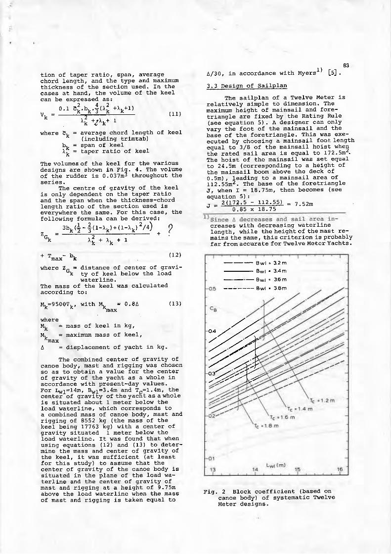
Fig. 2 Block coefficient (baseal oncanoe body) of systenatic TwelveMeter deslgns.
2
Bwl = 3 .2 m
B w l = 3 4 m_-_ ._ gw j : 36m
Bwl . 3.8m
%
t ion of taper ratio, span. averagechord length, and the type and maximumthickness of the section used' fn thecases at hand' the volume of the keelcan be expressed as:
' , t - - 8 3
A/30, in accordance v,t iCh I ' {yers" L5l .
3 . 3 D e s i q n o f s a i l p l a n
The saj- lplan of a Twelve Meter isrelat lvely slmple to dimension. Themaxinum height of mainsai l and fore-tr iangle are f ixed by the Rating RuIe(see equa t i on 5 ) . A des igne r can on l y
vary the foot of the nainsai l and thebase of the foretr iangLe. This l tas exe-ecuted by choosing a matnsai l foot lengthequal to 3,/8 of the rnainsai l hoist r^ 'heB
tl ie rated sai l area is equal to r '12.5m2.The hoist of the mainsai l was set equalt o 24 .5m ( co r respond ing t o a he lgh t o fthe mainsai l boom above the deck ofo .5n ) , l ead tnq t o a ma insa i l a rea o f112 .55m2 . The base o f t he f o re t r i ang leJ, \ , /hen I = I8.75m, then becones (see
equa t i on 5 ) :
. j - 2 1 L 7 2 . 5 - I I 2 . 5 5 ' J = i . 5 2 m- 0 - 8 5 x 1 8 . 7 5
creases with decreasj"ng waterl inelength, vrhi le the height of the nast re-nalns the same. this cri ter ion is probablyfar from accurate for Tr.Jelve Meter Yachts.
The volunes of the keel for the various
t t 2
* 0 . r e i . b k . i ( r i + l k + r )vk = -------:-2--:-.--.-
^k +/^k+ t
where Er. = average chord length' ' / i - ^ t ! ' A i h d + ? i h r - A t \ )
bt- = sPan of keel- - ! : - - r k e e l^ k - L a P s r
fol lowing formula can be derived:
3bL (+ - 4 ( r - l r . ) + (1 - r k ) 2 /4 )o - -----::---=---- - +'k t i + rk + 1
( 1 1 )
of keel
desl-gns are shown Ln Fig. 4. The volumeof the rudder is 0.037mJ throughout the
The centre of gravj. ty of the keelis only dependent on the taper rat ioand the span lrhen the thj-ckness-chordIength rat io of the section used iseverywhere the same. For this case, the
?
* TIn.*- bk (12\
where z- = distance of center of gravi-"k ty of keel below the load
waterline.The mass of the keel was calcul-ated
I " 1L=9500V1 , r , t i t h k - - 0 .84
"max
\,rhereMk = nass of keel 1n kg,
Mt = maximum mass of keelt_-max
A = displacement of yacht in kg.
( r 3 )
The conbined center of gravity ofcanoe body, mast and r igging stas chosenso as to obtain a value for the centerof gravl-ty of the yacht as a whole inacco rdance i { i t h p resen t -day va lues .Fo r l h , l =14n , 8 , . , r=3 .4n and T^= I . 4m, t hecen te l ' o f g rav i i y o f t he yacEL as a who leis situated about I meter belot theload vaterl ine, which corresponals toa combined mass of canoe body, mast andrigging of 8552 kg (the nass of thekeel being 17763 kg) with a center ofgravity sl tuated I meter below theIoad rvaterl ine. I t was found that whenus ing equa t i ons (12 ) and ( I 3 ) t o a l e te t -nine the mass anal center of gravity oft he kee l , i t was su f f i c i enc (a t l eas tfor this study) !o assume that thecenler of gravlty of the canoe body issLtuated ln lhe plane of the load vra-t e r l i ne and t he cen te r o f g rav i t y o fnas t and r i gg ing a t a he igh t o f 9 .75nabove the load inraterline rrhen the nassof mast and r igging is taken equal to
Fig. 2 Block coefficient (based oncanoe body) of systenatic Twefvet le te r des igns .
B w l = 3 2 m
B w l = 3 4 m---.- 8wl : 3.6 m
Bwl = 3.8m
tt
UnLike the mainsail, t l ,e actual area ofthe genoa is larger sl-nce only 85 percent of the foretriangle is rated, whilethe base of the genoa may overl'ap themainsail by an amount correspondj"ng toa length of 4.8m fron the foresl-de ofthe nast. This overlap is not lncludedin the rated sail area at all. I lence' inthe case of a rated sall area ofl?2 .5m2 and a maLnsa i l a rea o f 112.55n"the actual area of the genoa is1 8 . ? 5 x 7 . 5 2 x 0 . 5 + 4 . 8 x 1 8 . 7 5 x 0 . 5 = 1 1 5 . s n z .For other ratetl sail area values, thefoot of the mainsail and the base of theforetriangle ttere mul-tiplj-ed by a val-uek equal to:
. ac tua l ra ted sa i l a rea' -
1 7 2 . 5to obtaj"n corresponding sizes of mAin-sail and genoa.
In accoralance with Present-daypractice on Twelve Meters' the spinnakerboom was positLoned 5 meters above thedeck from the foot of the mast, and thearea-of the spinnaker was set equal to225m1. These spinnaker characteristicswere kept the same for all the yachts
85comprising the series.
3 .4 Rat lnq Charac ter is t i cs o f Sys terna t icTwelve Meter series
The dif ferent length ancl girthcharacterist j .cs ' as defined in theRating Rule' were calculated for eachtlesign to determine the al lowable ratedsai l area in accordance lr i th the RatingEquatlon (equation l) . The dependencyof the nain entLt ies in the RatingEquation on the length of the Load wa-terl ine, the beam on the vJaterl ine andthe canoe body draft, are shown inF i g s . 5 , 6 a n d 7 .
Flg. 5 shows the val-ue of the ratedlengith, as defined. by equation (2), asa function of Load r^'aterl ine length'beam and canoe body draft. From thisf igure i t fol lo\, ts that the smalles!rated length, for a given waterl inelength, is obtained for a large canoebody draft. In the region near lrr l=l3m'this is only due to a shorter Ll hui" lIength. For increasing waterl- ine lengths'howeve r , t he va lue o f f . 5 (2Gf -1 .2 ) be -comes Larger than 0'35n' at f i lst for
B w l - 3 2 m
B w l = 3 4 m
B w l = 3 6 m- - - - - - - Bw l = 3 .8m
T c = 1 2 m
T c - 1 - 6 m
T c = 1 . 8 m
B w l = 3 2 m
B w l = 3 a m
B w t = 3 6 m
B w t = 3 8 m
T c ' 1 6 m
Tc =1 4m
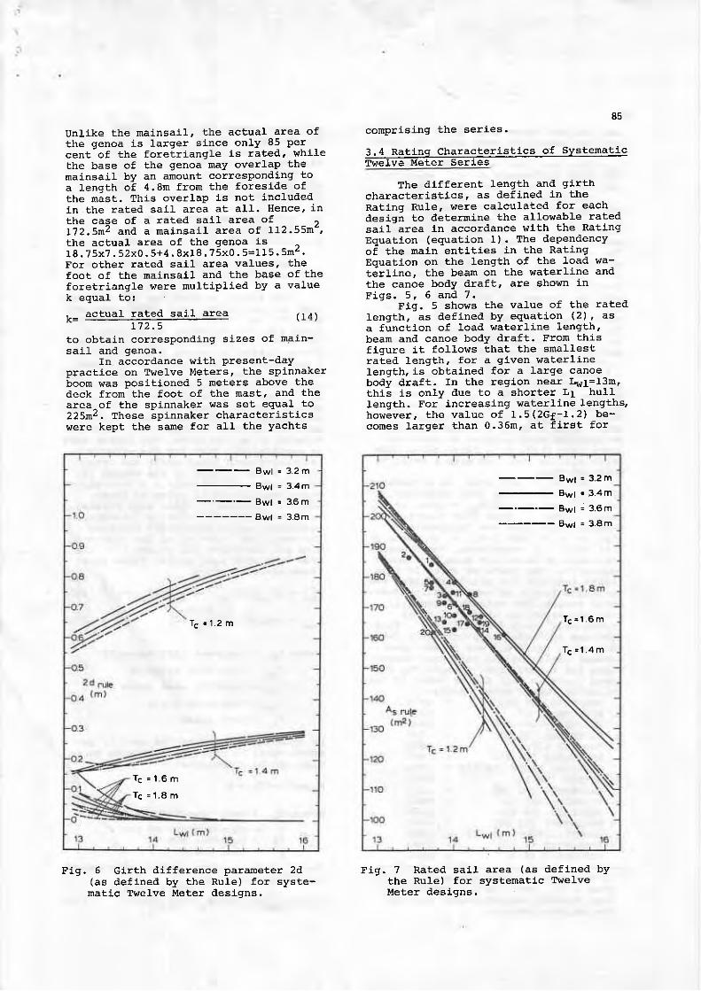
Fig. 6 cirth difference parameter 2d(as de f ined by the Ru le) fo r sys te-
mati.c Tlrelve lleter tleslgns.
Fig. 7 Rated sail area (as defined bythe Rule) for systenatlc Twelve!.!eter designs.

86
the snallest canoe body draft andsmallest waterline beam on1y, but grad-.ual1y also for T"=1'44 unti-r. near1 , , " .1= i6n , th is a lao occurs fo r Tc=I .6m'T f i6 q i r th d i f fe rence a t L rA ' equaf to126^-zn^l 11, never exceedEd r.2m.*
ThE dependency of the girth differ-ence parameter 2al on the length of theload rr'aterl ine' the maxirnum draft ofthecanoe body, and the beam on the Loadwaterline, is shown in Fig. 5' sincethe larqest difference between the skin-and chaingirth at the maximum sectionwill occur for the snallest canoe bodydraftl) , i t is not surprising to seethat the largest 2d value eventuatesfor T^=1, .2m. A lso fo r Tc=1.4m a re la t i -vely Iarge 2d val-ue stiI l occurs. Afact whlch is not so obvioug' ho\^/ever 'is that for snalf values of the maxijnumsectlon coefficient, such as occurs forIa.,r=l3m, a large canoe body draft anala"Iarge waterline beam, the sectionshape !ri1l not be without a shallol,hotiow. This is the reason for the small2d vaLues in F ig . 6 fo r these sases-These cases are not so interesting' how-ever, since usually a Large beam wlllbe combined with a small or moderatecanoe body draft or a large canoe bodydraft wil l be combined rr' i th a small ormoalerate beam.
The rated sail area, as a functionof the length on the load waterline'for different T- and B.-,1 values' isshown in tiq. 1l rron Lfi is f igure itbecomes clear just hoi! ' "expensive" ashallow canoe body draft is in terms ofsail area, In comparl-son, the oppositeinfluence of waterline beam is almostnegligible. The numbered spots in this-fi;ura indicate the rated. sai-1 area andwalerline length of some existlng Tr^'efveMeter Yachts. The data on rated sail"area anal waterline length of theseyachts were taken fron Hoyt [r] - Thisplot can be used to approximately deter-mine which trade-off lras establishedbetween sail area and main hull dilnen-slons for a partlcular design. The num-bered spots j"n this flgure refer to thefolloLring Twelve Meter Yachts.
- 1 9 5 8- 1 9 5 8- 1 9 5 8- 1 9 5 8
12. DAME PATTIE (KA 2) - 196713 . COLUMBIA (uS 16 ) - 196 ' l
CoURAGEOUS (US 26) - L97414 . TNTPEPTD (US 22 ) - r 97O
vAr,rANT (US 24) - L97O15 . GRETEL IT (KA 3 ) - I 97O15 . HERTTAGE (US 23 ) - 197017 . FRANCE (F r ) - 1970.r8. sourHERN CROSS (KA 4l ' 19'1419 . TNTREPID (U5 22 ) - 7974
tro. MARTNER (US 25) - 1974
4. DESCRIPTION OF THEORY ADOPTED FORCALCUI,ATING SAILTNG PERTORMANCE
The theory adopteal fo! the calcula-t ion of boat speed' heel and leeway an-gle, for any conbination of true windspeed and course angle, j .s simil_ar tothe method described by Myers L5l , Thetheory basical ly adopts 5 equations in5 unknowns. In addit ion to boat speed,heel and leeln'ay angle. the apParent rt lndangle and the apparent hrind speed arealso unknown. fn cornparison to Myerslmethod, however, some parts of the theoryhave been ref ined, l thi le other partsvrere not included because they \tere con-sidered to be too crude. The latter caseis part icularly true for the effectsassociaLed with rough water ani l roughair, A brief outl ine of the method isgiven belolr. In Appendix 2 a more elab-orate descript ion is given of thoseparts of the theory which vrere ref ined.
From the wind velocity tr iangle, 2equations qan be determined relat lngthe angle and velocity of the apparenthrind and the angle and velocity of thetrue wind n. l th boat speed. These equa-t ions are as fol lows:
tv:\, = (vtws in Btvr)
'+ (Vtwcos B tw+VB) - (r5)
l . coLUMarA (us 16)2 . SCEPTRI (K 17 )3. WIATHERI,Y (US 17)4. AASTERNER (US 18)5 . V r l 4 (US r5 )5. WEATHERLY (US 17) - T962
AMERICAN EAGLE (US 27\ - 19647. GRETEL (KA 1)8. EASTERNER (US 18)9 . COLUMBIA (US 16 )
INTRXPID (US 22)IO .NEFERTI f I (US I9 )
CONSTELLATTON (US 20) - 1964- L964- 1964
( 1 6 )
where Va!, = apparent wind velociey
V tw = t r ue w ind ve loc i t y- - ' - " a n g l epaw - a l i yar Er r u wr r ru
tstw = lrue w1no angre
v B - l v d L J P c E s
on equating the sum of the heeling mo-ments equal to zero the following equa-tLon can be formulated:
M"cos2o-Acz = o ( 1 7 )
v s a n s _, EW EW.
"aw
- 1962- 7962- 1962- 7967- L962
where Ms
tl ln the cases at hanal the section situ-
a ted 0 .55w I f r on t he Lv , ' I f oxe -end ing( the f o rwa rd pe rpend l cu la r ) i s a l sothe maximrn section.
Por B^- -<80o, the sa i l over tu rn ing momentcan b6"Expressed as:
= sai l overturning moment
= displacement of Yacht= r ighting arn= heel angle11 . SOVERETGN (K 1.2)
KURREWA V (K 3)
A
u"joorv]"r {c".cn.a") cose( r 8 )
vrhere p . .= nass dens l ty o f w lnd (a i r )
C = l i f t . d F f f i . i a n r - o f s a i l
cE = height of center of effort ofsa i l
As = sail area of each sall
. = F f f a ^ t i r r p d r : d - l i f t r a t i o o f' total sail areaThe surunatlon over C,.CE.A^ refers tothe summation of the"lrroduEt C,.CE.A^for each sail, over at1 the salls caF-rietl.For lhe mainsail the follovrinq valueswere used f5] :c L = 2 . 3 s 7 B a w - r . 0 ? 3 8 3 \ ,
c E = A / 3 + F M + M S B H
where A = height (hoist) of nainsail- ' '^ foot of nast
t4ier = hetgnt of tnainsail boonabove foot of mast
For the genoa the foll"ot ing values forC, and CE were usedt
c " = 0 . o a r B l o , + O , 3 4 4 B a w + r , 0 4
C E = I / 3 + F l lwhere I = height (hoist) of genoa
When p.r>80o, the sail overturning no-
ment is exDressed as:
ru"=|o"v]"r t c". cn. a, ) cos$ ( 2 1 )
where, for the nainsaif, Cl=1.2 with thesane cE as before.F ^ r + h 6 c h i h h . l a r .
tCL=- ' .2638; \ r + l .324Bae - 0 .3
CE= SIr/2 + FM + SPBH
r.there SL = helght of splnnaker
(221
SPBH = height of spinnaker boonabove foot of mast
The above values for C. were derivedfrom I'tyers [5] ,The effect of aspect ratio, camber, tr,ristand sheeting angles on l ift and drag arenot taken into account.
the value of the rlghting armt cZ,in equat ion ( I7 ) can be expressea l as :
G z = ( K M ( o ) - K G ) s l n O Q 3 ,where (M(0) = height of transverse meta-
cenlre above bottom ofkeel at tbe heel angleconsidered
KG = height of center of gravl-ty above bottom of keel
The sail drlving force must be inequil ibriun \.rith the to!a1 resistance ofl h e y a c h t . i . e . !
a7where F- = dr lv inq force of sal ls
R = f r i . r i d n F l r a < i s t a n c e- 'F
Rea = res la luary res is tance a t hee lang le Q
R = i n . l r r . : F d r F q i e f a n c e- ' rRW = wind resistance
In equation (24) effects associated withrough water and rough air are not in-cludeal. For 3 <8 0o:
s i n ( B a w - e s ) . c o s $
coses
(261
_ 1 - - 2! R=zPrdvavrl tuL'Asl ( 2 s )
( r 9 )
( 2 0 )
where C, of mainsai l and genoa are ale-f ined adcording t 'o equations (t9) and( 2 0 )
0 .089c . - ^ . .e"=o.oaafr-w u s r e n = a f f a d l - i r r a a ^ . + ^ t s - r
" eff sai l area
when 8 . ">80o , t he f o t l ow ing re l a t i on f o r!R as useo :
1 )FR=ipwv;wt ( cLAs ) cososin-i (21)
lrhere CL of mainsaLl equals 1.2 and CL
for the spinnaker is according to equa-t i o n ( 2 2 ) .
The wind resistance is calculated. ^ ^ ^ r : I - - + ^
1 )Rw=ipvrv;wcl. Awcos Baw ( 2 8 )
r^there A,., = frontal area exposeal to wind* o f mast , r igg ing , hu1 l andqfew
In equat ion (28) C, was se t equa l tounity.
The calculation of the frlctionalresistancer the resid.uary resistance andthe intluced reslstance is described inAppendix 2.
Equil ibriun of the forces acting onthe yacht in the lateral direction re-sults in the following equatl-on!
c l ! -_ o t _ db' K t* -t9) B*=o l2g)' r,'^wr,-"rr-. nuD- tiIB;*aE;**_h ..
where FL = lateral sail force
R- = Iateral winal resistanceto l .ce
F-- = lateral force due to t r imtab
F---- = lateral force due to rudder- RUD' - - - - due t o kee l' k
F-,- = lateral force due to skeg
F- = Iateral force due to canoe- boaly
Bh = leeway (dri f t) an91e
For R >80o the ' l a t e ra l
sa i l f o r ce can_ - - - aw- - -
be expresseal as:
- r _ _ 2 - , _ -! L=ZPvrvawr tuLAs, .cos . ( Baw-e s ) . coso
( 3 0 )
F n - R r - R n - R t - R W = 0 ( 2 4 l
coses

l rhere c. of mainsai l equals r.2 and cL
of the €pinnaker is defined accorctLng
to equa t i on (22 ) .-- -='r;" iaterai wincl resistance can be
r"=!orv]rr tc".n") cos!. coso
expresseal as:
n"o=|o"v],oco.n"osine."
88where c. of rnainsall and genoa are cal-
.ot.t"dt.aaotding to equations (19) and
i r0 ; ; - " "4 i - acc6rd ins to equat ion (26) '
nor '&- - tgOo the la te ra l sa i l fo rce can
be e*Piessed as:
V-. d and B. is carried out by means of
af i ieratioff procedure in vF' Afterchoosinq an lnittat value f6r vR' lorgiven vtlues fo: Yt, and 8a"r v;w andA are calcuraceqi?Bn ( rS) and (16) . An i te ra t lon Proce-a;;; i; ihen carrled out, starting with
[-]-ol- a"-'a.t.rnlne the heel angte which
l . t i i i i e " equat ion (17) . The hee l ang le
rt".-i" u" i icreased if the left-hand"ia.
-ot- "q"u cion (r7) is positive and has
il-i.-a""i".".d r'then the left-hand slde
i" "eq"tf.te. With the resulting values7^- e - - v and 6 , s t i t l fo r the or ig i -
i"rriu8fi""8H v,. ihe vafue of the leeway
anqli is then Ealculate'l from equatron
l -Jd t . i i " " r ry , the vaLue-o f the le f t -hand s ide o f equat lon (24) i s ca lcu la ted 'i i--lr: i" vatue is negatlve, the original-iv chosen v--value is too large becauselit""--irt. suft of the hytlrodynamic resis-i in.. .o*pott"ttts is too high' rf the-le f t -hand s ide o f equat ion (24) resur tsin ""i it i . '" values, the orlginally chosen
;- ;; l;" is too snarr. on rePeatinq the
;B.;i;t; piocedure for 2 nore boat speed
"ii i .., "it" of which is too snall and one
"i-tttf"n ls loo large' it is possible to
( 3 r )
(32 \
where &.- = Iateral area exposed-to windof nas t ' r lgg ing , nur l anocrew
rn equat ion (32) , as in equat ion (28) 'C- was set equal to unity.-L
nrr" cal;ulalion of the total hydro-avnanic side force due to keel' tr intab'.irJJ"i, "r"s and canoe body ts describedin Appendix 2.-- "irr"
solution of equations (15) '( 1 6 ) , ( 1 7 ) , ( 2 4 ) a n d ( 2 9 ) f o \ v . r ' 8 6 1 ' ,
Vtw ' 6 knots--- Tc
-.--- Tc------- Tc
= 1 . 2 m
= 1 . 6 m
. 1 . 8 mheodirE ongle 90'{ reoching )
VB (krDrs)
t*Oino onoe tao' \
( rlrnnrig wlttrspinnokef)
'---*a
14 L* r ( - )
Fiq. I calculated boat speed for a true- wind sDeed of 6 knots (effect of LwIanil Tc-on running and reachinq) '
' ' |B w l = 3 2 m
B w l = 3 4 m
Bwl = 36m
B w l = 3 8 m
Lw l (m)
heoding ongle l8o'(running with spinnoker )
F ig , 9 Ca tcuJ -a ted boa t speed fo r a t r ue- ' reind speed of 6 knots (effect of twl
and er1 on running and reachinq) '

estlmate, by inlerpolation' a correctedvo va lue fu l f i l l i nq equat ion (24) qu i tec lose ly . For th is cor rec ted vn va lue thecomplete process is repeated'-again alsofor a larger and a smaller vafue for vF.Usualty after 4 or 5 of these lteratiohs'the boat speed is determined within theset accuracy.
In the above alescription of thetheoretical nodeL for the calculationof the sail ing performance of yachts'some important aspects are not dealtrrith. One of these Ls the calculation ofthe effective true rrLnd velocity foreach of the sails fron the input valuevalj-d at the top of the nast. Thj-s isnecessary since the true winal speedincreases vrith helghu above sea 1evel.Another aspect not dealt with in theabove descrl.ption is the effective in-crease in waterline Length lrhen theyacht heels to some heel angle 0.
895. RESULTS OF SAILING PERFORMANCE CAI.CU.LATIONS FOR SYSTEMATIC TWELVE METERSERIES
5.1". Running and Reaching
Results of perfornance calculationsfor the running condltionr with spinnaker'at heading angles of 1800 and I40o, andfor the reachlng condition at a headingang le o f 90o, a re shown in F iguresS ' 910, L l , 12 and 13 . Thege f igures showthe calculated boat speed as a functionof waterline tength for different T^and B--r values. Three true wind speEdva lueE 'are cons idered: 6 , L5 and 24knots .
Figures 8 and 9 show the resultsfor a true wind speecl of 6 knots. As canbe seen, the j-nfluence of waterll"nelength is very significant. The snallestpossible yacht' vrigh the largest Possiblesa i l a rea , w i l l per fo rm the bes t . The in -fluence of canoe body draft is also verysignificant as can be seen fron Figure 8.This influence can be nearly conpletelyexpl"ained by the fact tha! ghe largevalue for the gtrth differenqe parameter
Fig. I0 Calculated boat speecl for atrue wind speed of t5 knots (effect
of twl and Tc on running andreacn ] . ng r ,
Vtw = 15 knotsB w t = 3 2 mg w l = 3 4 m
Bwt = 36m
Bwl = 3'8m
14 Lwl (m )
hmding ongle 90"(reoching)
heoding ongle 18d( running with spinnoker)
-Fig. 11 Calculated boat speed for atrue wind speeal of 15 knots (effectof Lwl anal Bw1 on running andreacnangr .
T c - l 2 m
T c ' 1 4 m
T c = 1 6 m
T c = 1 8 m
heoding ongte lzlo'(running with spirhoker)
heoding ongre re-oN-*=(running with spinnoke.)
Lwl (m )
neoor{l ongre 9u
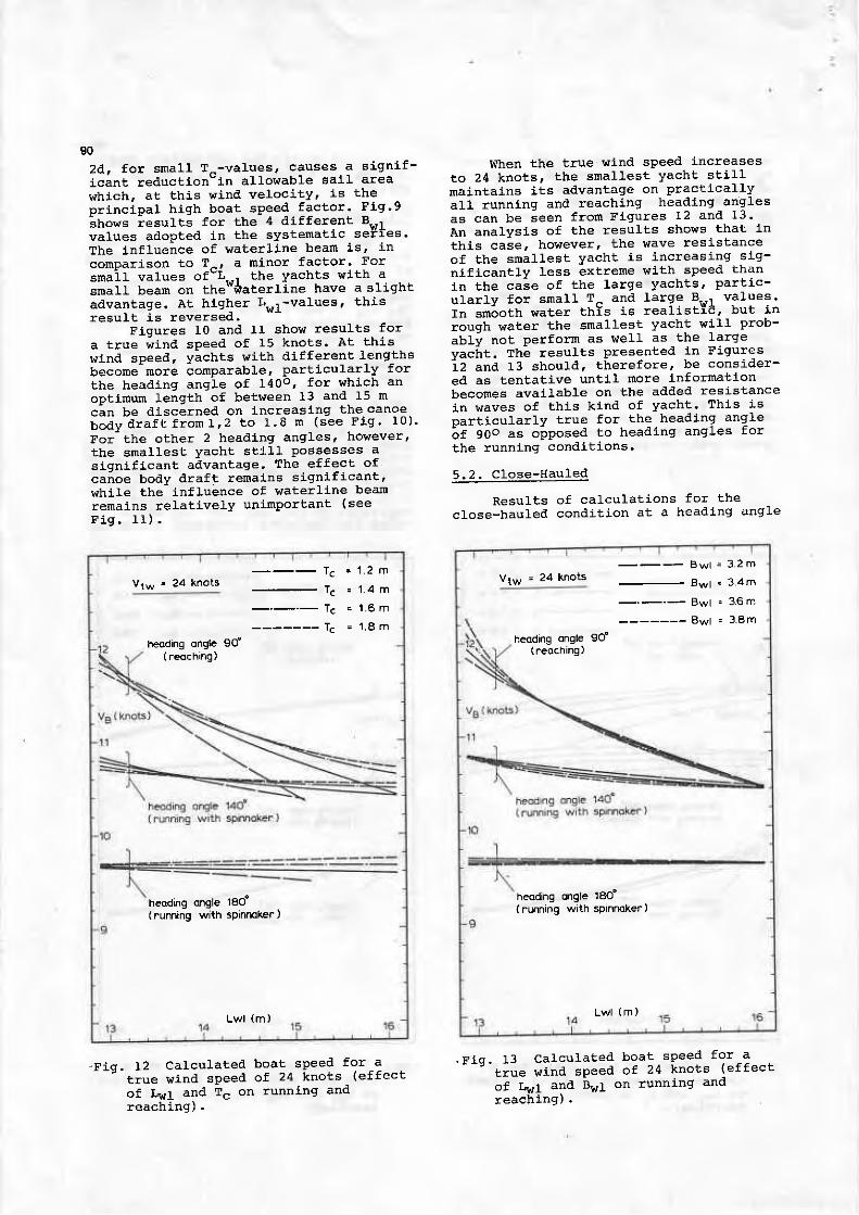
90
2a l , f o r sna l l T^ - va lues , causes a s i gn i f -icant reduction' ln al lowable sai l area
which, at thls wind velocity ' ls thep r i nc ipa l h i gh boa t sPeed fac to r . F i g ' 9
ihows resulcs for the 4 al i f ferent Bwl
values adopted in the systematlc seraes'
The lnf luence of waterl ine beam is, in
conpa.r ison to 1^, a ninor factor. For
snai l values of"L--" the yachts wlth asmall bearn on the**aterl ine have a sl ight
advantage. At higher Lwl-values ' thisrasu l t i s r eve rsec l .
Fiqures I0 and II show results for
a true wind speed of 15 knots. At thi.s
lr lnd speed. yachts with t l i f ferent lengths
becotne- more -ornparable, particularly for
the headlng angLe of 1400, for which an
optirnum length of bete/een 13 and 15 m
c-an be discerneal on lncreasing the canoe.
b o d y d r a f t f r o m 1 , 2 t o 1 . 8 m ( s e e F I g . r u ) '
For the other 2 headl-ng angles' however'the smallest yacht st i l l possesses asignif icant advantage. The effect ofcanoe body draft renains signif icant 'whi le the inf luence of waterl ine beamremains relat ively uninPortant ( seeF i g . l 1 ) .
When the true '.Jind speed increasesto 24 knots , the smal les t yacht s t i l lmaintains its advantage on placticallyal,1 running and reaching heatllng angl"esas can be leen frorn Fiqures t2 and 13.An analysi.s of the resutts sho!,s that inthis case, however, the wave resistanceof the snallest yacht is increasing saq-nificantly less extreme with sPeed i:han1n the case of the large yachts. partic-ularlv for srnall T^ and large B,.,! values'In srnaoth water thYs is realistie, but inroush water the smallest yacht v'1I] Prob-abli not perforln as well as the largevacirt. rne resulls presentecl in Figuresiz ana t3 should, therefore, be consider-ed as tentative untl l nore inforrnationbecomes avail-able on the aalded resistancein waves of this kind of yacht. This isDarticularlv true for the heading angle6 i soo . . o iposed to head ing ang les fo rthe running conditions.
5 .2 . C lose-Hau led
Results of calculations for theclose-hauled conditlon at a heading angl-e
B w l = 3 2 m
B w l ' 3 4 m
B w l ' 3 6 m
B w l = 3 8 m
heoding ongle 90'(aeoching)
Lw l (m)
heoding ongle 18o'( running with spinnoker)
'F iq . 13 Ca lcu la ted boat sPeed fo r -a- - ' ' t i , . t " w lnd speed o f 24 knots (e f fec t
of rr,If ana B"1 on runni'ng andreaqh ing) .
Vtw ' 24 knotsT c ' 1 2 m
T c = 1 4 m
T c = ' 1 6 m
T c = l 8 m
Lwl (m )
heodng onge 9u( reoching)
heoding ongle 18o'(running with spinnokea )
' r i q . t2 Ca lcu la ted boat speed fo r -a' true wind speed of 24 knots (effect
of LwI and Tc on runnlng andreach j -ng) .
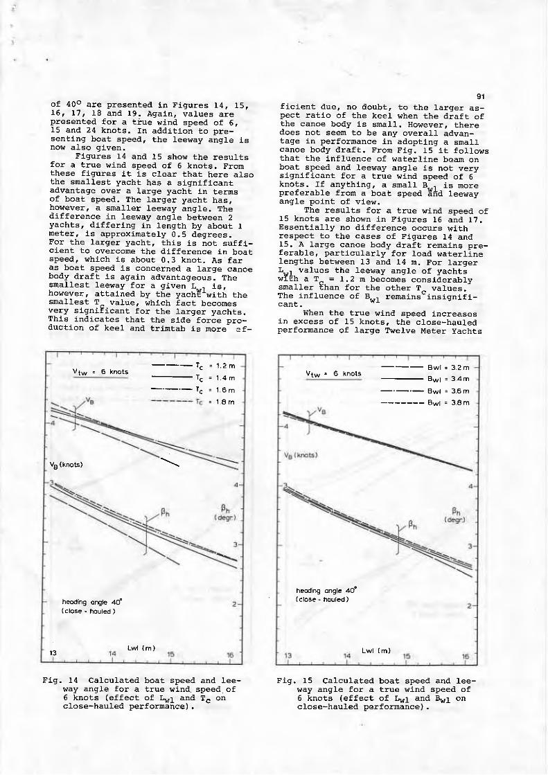
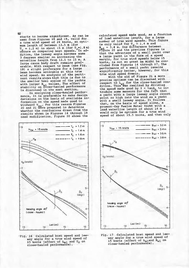
of 40o are presentetl ln Figures 14, 15,15 , f 7 , 18 and 19 . Aga in , va lues a represented for a t iue wind speed of 6,15 and 24 kno ts . I n add i t i on t o l ] rF -senting boat speetl . the f".""V-"I i i . f"now also given.
Figures 14 and t5 show the resultsfor a true wind speed of 6 knots. Fromthese f igures i t is clear that here alsothe sma l l es t yach t has a s i gn i f i can tadvantage over a large yacht ln ternsof boat speed. The larger yacht has,however, a snal ler leevray angle. Thedifference in leeway angle between 2yachts, dif ferlng in length by about Ineter, is approximately 0,5 degrees.For the larger yacht. this is not suff i-cient to ovelcome the dif ference ln boatspeed, n'hLch is about 0.3 knot. As faras boat speed Ls concerned a large canoebody draft is again advantageous, Thesna l l es t l eeway f o r a g i ven L - - i i s ,however, attained by the yacht 'with thesmallest T^ value, which fact becomesvery signif icant for the .Iarger yachts.This indicates that the slda fnrce -.^-duction or re.r ."J il^t"[-i=-iJi."Jr-
FLg. 14 Calculated. boat speed and 1ee-way angl-e for a true wind speed of6 . kno ts (e f f ec t
9 f r " f and Tc oncrose-nauleo perrormanceJ .
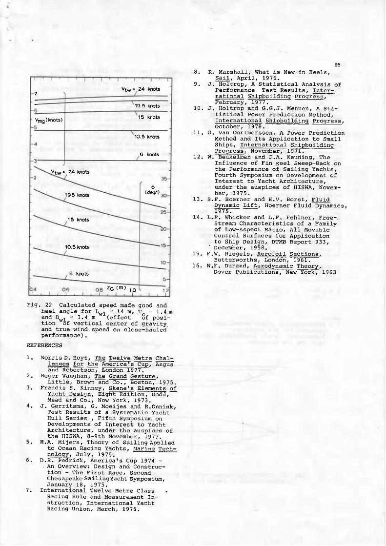
91ficient due, no doubt, to the larger as-pect rat io of the keel when the draft ofthe canoe body is small . However, theredoes not seem to be any overal l advan-tage in performance in adoptinq a snalfcanoe body draft. Fron F19. t5 i t fol lowsthat the lnf luence of rraterl ine bearn onboat speed and leeway angle is not verysignif icant for a true wind speed of 6knots. f f anything, a small B.-.r is norepreferable from a boat speed 5fid leewayangle point of view.
The results for a true wind speed of15 knots are shown in Figures 16 and 17.Essential ly no dif ference occurs withrespect to the cases of Fj-gures t4 and15. A large canoe body draft rernains pre-ferable, part. icularly for load t aterl inelengths between L3 and 14 n. For larqerLul values the feei,ray angJe of yachtiw i t h a r ^ = 1 .2 n become i cons ide rab l ysmaller Ehan for the other T^ values.The inf luence of B.,,r remains" insigni f i -can t -
When the true wind speed increasesin excess of 15 knots, the close-hauledperfornance of large Twelve Meter yachts
B w l = 3 2 m
B w l = 3 4 m
Bwl = 3-6 m
B w l " 3 8 m
heoding onglc 4Cf(c lose - houled )
Lw l (m)
___ Tc
_._._ lc
= 1 . 2 m
= 1 . 8 m
VE (knoG)
heoding ongb 4d(close - houted )
't3 Lwl {m)
Fig. 15 Calculated boat speed and lee-way angle for a true wind speed of5 knots (effect of Lwl and Bvl onclose-hauLed performance),
92starts to becone significant. As can beseen from Figures r8 and 19, valit l fora true wind speed of 24 knots, an optl-mum lensth of between r3.5 n (forr = t . 5 m ) t o a b o u L 1 5 n ( f o r T - = 1 ' 8 m )o8",rt" on comparing boat speeds.-In ad-dition' the leeway an91e becomes sone3 deqrees smaller on increasing thewate i l ine length f rom 13.5 to 15 n ' AIarge canoe body draft remains Pre:-e rab le . w i th respec t to beam (see F lg '19) a sliqht Preferance for a largebeam becomes noticable at this truewind speed. An analysis of the perti-nent rasults shows that this is due tothe snaller heel angles of the yachts* i th l . to . t g - - , va tues . The e f fec t o fstabitiLt on Etose-hauted perforrnanceis dlscussed l-n the next section'
In analysing close-haul'ed perfor-mance, it is preferable to make designdec is ions on Lhe bas is o f ava i lab le in -fornation on the sPeed made good towindward v--. For this reason Figures20 and 2I i lEre prepared to i leterminewhether the conalu;ions drawn from theresui-ts shown in Figures 14 through 19need modification. Figure 20 shows the
'Fig. f5 Calculated boat speed and-lee-vrav anqle for a true r.vind speed of
ts-knols (effect of l , !r1 and Tc on
close-hauled Performance) .
calculated speecl made good. as a functlon
of load watei l ine l-ength, for a large
number of true wind speeils. This f igure
is onlv val- j . t l for T^ = I.4 m and
e = l . a m . one d i f f e rence be tween
nY*ure 20 and the previous f igures rs
th;t the advantage of a small yacht over
a .Iarge Yacht In the forn of a sPeed
marqi i , ior true wint l speeds befow 15
knols, ls not so great as might be con-
cluded frorn Figures 14 through 17' The
performance of a small yacht remaj.ns' s i qn i f i cane l y
be t t e r , howeve r ' f o r t h i s
true wind speeal domain.with the ald of Flgure 21 a nore
oreclse optlmum can be discerned with
iespect t ; L--" for the close-hauled con-
d i t i on . Th i s *das rea l i zed by d i v i d i ng
the speeal nade good by 1 + tanBh to j-n-
trodule sorne neasure for the fadt that
a vacht lr i th a large leeway an91e cannot
ooint as high into the wind as a yacht
; i th a smatl leeway angLe. I t fof lov"s
that, on the basis of sPeed alone' a
Dres;nt-day Twelve Meter Yacht I t i th a
ioad waterl ine Length of about 14 m
would only be oPtinum for a true wind
ipeed of i lout ig.s knots' and then only
15 knotsB w l - 3 2 m
B w l = 3 4 m
B w t ' 3 6 m
B w l = 3 8 m
Lwl (m )
heoding ongle 40'
{c lose - houled )
_ - - T c : 1 2 m
- T c : 1 _ 4 m
_ . _ . _ T c : 1 6 m
- - - - - - - Tc = 18m
\ = _ _
Lwr (m)
heoding ongle 40'( close - houled )
Fig. 17 Calculated boat spee' l and-lee-
wav anqle for a true win'l speed of
t5-knols (effect of Lwland Bwl on
close-hauled Perfornance) .

for the close-hauled condit ion.I n F igu re 2 I , t he op t imum head ing
ls also presented as a function of truelr ind speed and waterl lne length. Fronthis f lgure i t appears that for truer,t ind speeds below about 12.5 knots, theoptiroun heading angle decreases on in-creasing the load waterl ine, whlle forhigher lr ind speeds the reverse ls true.This should be taken lnto account innaking a decislon on the optlmum L..1value for a certaln rn' ind speed.
93
dj-splacenent ratio of these yachts. Atypical val-ue of the distance of the ver-tical cenler of gravlty below the loadwaterline of a moilern Twelve Meter is inthe order of I m. A further inqrease instabil ity !,ri l l be very dlff l.cult to real-lze. For l19ht wlnds, the results qlvenin Fl,gure 22 lndicate that only a nargin-al improvement in performance can be at-tained by increasing stabil lty,
6. FINAL REI.4ARKS AND CONCLUSIONS
A study such as Is reported in thispaper must be considered preliminary andtentative untLl confirnation is obtai-netlfrom actual nodel or full-scale neasure-ments. Nevertheless, a compLete theoret-ical approach in determining the saj-l ingperfornance of a yacht has already beensholrn to be qualitatively correct so thatthere L'ould seem to be very l itt le basisto distrus! the results lf consldered ona comparative base. If these results areconsidered to be qualltatively correctthe follovring conclusions can then bealrawn:
Flgure 22 presents the results ofspeed made qood calculat ions for dif fer-ent values of the location of the ver-t ical center of gravity below the loadwa te r l l ne 2 . . Fo r t h i s f i gu re L . , , 1=14 m ,8 . . 1=3 .4 rn a i d T_ = I . 4 m . The ma i f i r e -s f i l t s o f t hese Ea l cu la t i ons a re t ha tfor high Lrind speeds an increase in sta-bi l i ty results in an apprecLable in-c rease i n V_^ . P resen t -day Twe lve Me te rYachts, how€Ver, already have a largestabi l i ty due to the very large bal last/
Fig. r8 CalcuLated boat speed and lee;way angle for a true \^' l"nd speed of'24 knots (effect of Lwl and Tc onclose-hauled performance) .
vtw = 24 knotsB w l ' 3 . 2 m
Bwl = 3 4rn
B w l = 3 6 m
B w l = 3 8 m
ph
9rt(degn)
heoding ongle 4d( close - houled )
Lwl (m )
VA ( knots )
Fig. L9 calculated boat speed and 1ee-way angle for a true wind sPeed of24 knots (effect of LwI and Bul onclose-hauled perf ornance) .
5 .3 . E f f ec t s o f s tab i l i t v on C lose -HauIed Performance
T c ' 1 2 m
T c = 1 6 m
T c " 1 8 m
heoding ongle 40'{ close - houled )

94
-F ig . 20 ca l cu la ted boa t speed made qoodana l l eeway ang le f o r Tc= I . 4m andB , - , r - 3 . 4 m ( e f f e c L o f L L , t a n d t r u e w i n ds iEea on c l ose -hau l ed Fe r fo rmance ) .
The rBost important question to be an-swereal before desiqning a fwelve Meteris whether the yacht must perform bestin the close-hauled condit ion in truewind speeds in excess of approximately15 knots, or whether the Yacht mustperforn best in l t ind speeds not exceeal-i ng 15 kno ts , i n r 1 ' h i ch case no d i f f e r -en t i a t i on i s necessa ry be tween thed i f f e ren t po in t s o f sa i l i ng .
For true wind speeds not exceeding ap-ploximately t5 knots, the optimum Twelvel l e te r s i ze seems to be cons . i de rab l ysma l l e r t han p resen t -day des igns .
A l a rge va lue o f t he g i r t h d i f f e rencefactor 2d nearly alv"ays leads for al ltrue wind speeds considereal to non-optimum periormance. This is val id forrunn ing , r each ing and bea t i ng . A conse -quence of this is the f inding that aIarge canoe body draft leads to betterpe r fo rmance .
A na jo r e f f ec t assoc ia ted w i t h t he beamon the \raterl ine coul-d not be founalexcep t f o r a s l i gh t p re fe rence f o r asmalf waterl ine beam for a snal l t lvelve
l4e te r .
- A large beam and a low posit ion of thecenter of gravity improves the close-hau led pe r fo rnance f o r h i gh t r ue w indspeea l s .
on t he bas i s o f t hese conc lus ions i tw o u l d s e e m c h a t L h e o v e r a l l s a i l i n g p e r -
formance of present-day Twelve l{etelYachts can be improved upon in true winalspeeds up t o abou t 15 kno ts . I t wou ld a l so
seem tha t i n t ha t case i t i s i nco r rec tnot to maximize the al lowable sai l area
wh ich , on t he bas i s o f l he resu l t s shownin F igu re 7 , i s r a re l y ca r r i ed ou t . Thenon-optimum performance of some recentTvrelve tr leter Yachts l t i th a large l taterl ine
leng lh o r a sna f . I sa i i a rea seems Lo beexp la ined .
F lq . 21 . Ca tcu la ted speed maa le good ,
corrected for leeway, and optlmunh e a d i n g a n q l e f o r T c - I . 4 m a n dB . , r - 3 . 4 n ( e f f e c t o f L . , r a n d L r L l e w i n ds i6ea on c l ose -hau led " i e r f o rmance ) '
Lwl ( m)
19 5 knots
24 knots
7
19.5 knots
Vmg ( knots )15 knots
1O.5 knots
6 knots
ytw.. 24 knots
19.5 knotsa
(d€r)
15 knots
10.5 kmis
6 knots
ZG (m) t .o
! 4ead and Co , , New Yo rk . 1973 ,,J. Gerri tsrna, c. Moeljes and R.Onnink,
Test Results of a Systematic yachtHulI Series r Fif th Symposlum onDevelopments of Interest to yachtArchitecture, under the auspices oft he H ISWA, 8 -9 th Novenbe r , 1977 .
H .A , M i j e r s , Theo ry o f Sa i l i ng App l i edto Ocean Racinq Yachts, ! .rarine lech-l g l ogy , , Ju ry , r 9 l 5 .
D .R . Ped r i ck , Amer i ca rs Cup 1974 -. An Ovelview: Design and Construc-
t ion - The First Race, SecondChesapeake Sail ingYacht Syrnposium,J a n u a r y 1 8 , I 9 7 5 .
International Tnrelve Metre Clas sRacing Rule and Measureuent In-struct ion. fnternational YachtRac ing Un ion , March , I 976 .
g5
8. R. Marshall , lalhat is New in Kee1s.€gq , Ap r i l , I 976 .
9 . , t . Ho f t r op , A S ta t i s t i ca l Ana l ys i s o fPerformance Test Results, fnter-national Shipbui ldinq progrEEE-Feb rua ry , 1977 .
10 . J . Ho l t r op and G .G ,J . Mennen , A S ta -t l s t i ca l Po \ , r e r P red i c t l on Me thod ,I n te rna t l ona l Sh ipbu i l d i ng P rog ress ,dcto5er. T978--.:
11. c, van Ooitmerssen, A Power predict ionMethod and Its Appl- icat ion to Sma11Ships, InternatLonal Shipbui ldingProg ress , November . 1971 .
12 . W. Beuke lman and J ,A . Keud inq , TheInfluence of Fin Keel Si,reep-Back onthe Pe r fo rmance o f Sa i l i ng Yach ts ,Fourth Symposium on Development offnterest to Yacht Archl lecture,under the auspices of HISWA, Novem-b e r . 1 9 7 5 ,
1 3 . S . F . H o e r n e r a n d H . V . B o r s t ,Dynamic lt:!q!. Hoerner Fluid79'7 5 .
14 . L .F . Wh icke r and L .F . Feh lne r . F ree - .Stream Characterist ics of a Familyof Low-Aspect Rati .o, A1l- MovableControl Surfaces for Appficationto Sh ip Des ign , DTMB Repo r t 933 ,' Dece rnbe r . 1958 ,
15 . F .W. R iege l s . Ae ro fo i l Sec t i ons ,Bu t t e rwo r ths , London , I 961 .
16 . W.F . Du rand , Ae rodynamic I IS9 I I ,Dover Publications, Nerit Yorkr I963
Dynamics,
Fig. 22 Calculated speed nade good andhee l ang le f o r L , . , . r = t 4 m , T^ = I . 4 r nand B , . , r = 3 .4 m
" - (e f f ec t 6 f pos i -
t i on "d f
ve r t i ca f cen te r o f q rav i cvanal_true r,r ind speed on closelhauleipe r !o rmance r .
REFERENCES
l . No r r i sD . Hov t , The Twe lve Me t re Cha I -lenses foi S!_g-gE;i;;-is-G; A"9".and Robe r t son , London 1977 .
2 , Roge r Vaughan , The Grand Ges tu re ,Lirt lef Bro!rn-and-t6; B6;Ed; 19 75.
3 . F ranc j , s S . K inney , Skene rs E le rnen ts o fYacht Design, Eight Edit ion. Dodd,
! ruad
7 ,
96
Appendix No. I
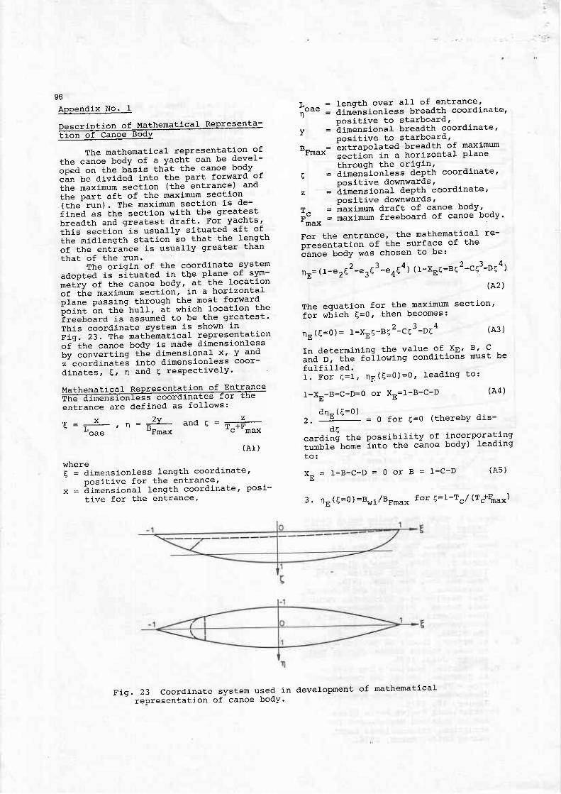
Desc r i o t i on o f Me thema t i ca l Rep resen ta -
t ion of Canoe BodY
The mathematical representation of
the canoe body of a yacht can be devel-
oped on Ehe basis that the canoe booy
I!"-U. ai" ia.a into the part forward of
the maxinum sectlon (the entrance) ano
the part aft of the maxlmum secclon
i f ne ' r un ) . The max imum sec t i on i s t l e -
i ined as the sectj-on with the greatest
u i " i a tn and g rea tes t d ra f t . Fo r yach ts '
t f t is section-is usually si l :uated aft of
ihe miafength stat ion so that the lenqth
of the ent;ance is usually greater than
that of the run 'The origin of the coordinate systet l
adooted is si tuaeed in the plane of sl 'm-
metiv of Lhe canoe body, at the location
oi l i re maximurn secLion, in a horizontal
oi. t t . oa". i t tq through the most forvtar ' l
i " i " t L " t he hu1 l , a t wh i ch t oca t j on t he
ireeboard is assumeal to be the greatest '
This coordinate systen is shown in
r i o . z : . The na th ;ma t i ca l r ep resen taL ion
o i - t ha . . t t o . body i s made ' l imens ion less
by convert ing the dimensional x' y and
z- coordinatei into dinensionless coor-
d ina tes , 6 , n and 4 resPec t i ve l y '
entrance are defined as f oI lor ' /s:
E = ---I-, " = #- and r = rcft;"oae -Fmax
(A1 )
whereE = d imens ion less l eng th coo rd inaLe ,
posit ive for the entrance.x = i imensional length coordinate, posi-
t ive for the entrance '
T . = I enq th ove r a l l o f en t rance ,loae = aln6nsionless breadth coordinate'
Dos i t i ve t o s ta rboa rd ,v = dimensional breadth coordinate,'
oos l t i ve t o s ta rboa rd ,B*---= LxtraPolated breadth of maximrm- fmax
sec t i 6n i n a ho r i zon ta l P fanethrough the origan,
! = dinen;ionless deplh cooral inate,
Posit ive alownwards," = l i r nens iona f dep th coo rd ina te '
Dosit ive downwar' ls,n = i taxirnum draft of canoe body,
;c = maxinum freeboard of canoe body'- max
For the entrance' the mathematical re-
p resen ta t i on o f t he su r face o f t he
ianoe body was chosen to be:
A ) . l 4 .no= l r -e rEz-erE -e4€ ' ) ( r -XE( -BL - -c 6 - -Dq
- )
(A2 )
The equation for the maxinum section'fo r w l i i ch q=0, then becones:
ng (E=o) = l-xEa.,Be2 -ca3 -DeA (A3 )
I n de te rm in ing t he va lue o f XE ' B ' c
and D, the fol lowing con' l j - t ions nus! De
fu l f i l l ed .1 . ! ' o r 4 = 1 , n g ( E = 0 ) = 0 ' l e a d i n g t o :
I-x"-B-c-D=0 or xE=l-B-c-D (A4 )
dn - ( €=0 )Z- --!--L--- = O for t ,=O (thereby dis-
d rcaraini the Possibil i ty of incorporatj-ngt"*Ui"'rr"*" into the clnoe body) leading
t o :
Xe = 1-B-c -D = O or B = I -c -D (A5)
3 . n " (6=0)=Br I /BF*ax fo r 6= t -Tc l (T i f {nax)
F i g . 2 3 c o o r d i n a t eY 6 n r 6 c a n + r f i ^ n
system useal ino f canoe body .
development of mathematical
(thereby requir ing that on the load r,ra-terl ine the beam of the maximum sectioni s equa l t o Bw I ) l ead ing t o :
b - r + ( r + r ) 2 - D ( ( r - r ) 2 - ( r - r ) 4 )C=
* ; : : (A6 )
( 1 - r ) ' - ( 1 - r ) -
where t=Tc/ (Tc+Fmax) and bw=BLrllBp^ax
t4. rltnE
(q=0) dl=chbwt (thereby requil ing
that the naximum section has a certalnsection coefflcient defined asca= (An/ ( \ r .Tc) ) lead ing to :
! t ?c 6 b w c = 1 - ( r - r ) - ; ( r - ( r - r ) " ) j ( 1 - ( r - r ) ' ) +
n q
- ( r - ( r - t ) - )
On subsLiluting for B and C the expres-sions according to {A5) and (A6) , thisIeads to D=DI /D2, \ , rhere :
r - , r - * t 3D]=CEb, . , t - t+ (+ ) i
r i - , ' - . t 3 ' , - , , - * t 4/L. - r t / r _+ \ - \ ,:_--t_i_-_=_ _ i__.!_:___:Lr
- -( r - t ) ' - ( 1 - r ) -
^ r - ( r - r ) 3 r - ( r - t ) 5 ( r - r ) 2 - ( 1 - r ) 4"2=----5--__--5-- ; : l - l l l l - l l l - l l l l � � .
t - . - r ) ' - ( r - t ) '
, r - ( r - r ) 3 r - ( r - r ) 4 ,, 3 - ---v- t
97which has the property that for 6=0'4 -^= I (sa t is fy ing equat ion (A4) ) , andaIEo the property that for €=I, 4pe=0which is necessary since for q=r 'the
profi le or centerplane of the canoebody intersects the sheer lLne in thehorizontal plane chrough the origin forwhlch L=0. The value of the constant uin equation (AI2) j-s determined by re-qui.ring that the profi le of the canoebody nust satisfy the requirenent thatE=Lwle/Loae for _g=1-1 -(thereby requiringthat on the load waterl-ine the lengthof the entrance j-s equal to Lwle). whlchleads to :
r w ^ - cu=--j---------= (Al 3 )
rwl - rw!
"n".J tr" I ""r.r"o".,on further requiring that the Load vra-terl ine has a speclf ied half angle ofentrance, i t is necessary thatdn - - 2L - - , ^=+ = ;*" . tan io for !=I-t andol 6wI
E=lwo rn'hich, on dif ferentiat ing equation(Al.); wlth use of equation (Att) alt l(A r2 ) , and on subs t i t u t i ng f o r e2 t heexpression accordlng to equation (A9),leads to:
l ^ - l ? - e 4 ( I r - I 2 )e?=.".. :---- ' 3 ' 2
(Ar4 )
ln whi.ch
r^=-3L"r" ran iFr (B ( r -r) + 2c lL-tl2 +- "w1
+3D (r- t ) 3 + 1!) . tzurr .+a (r-u) 1w3)
12= (B ( 1-r) +2c (r- t ) 2+:o t r - t ) 35!)
. ( 2urw:+4 ( r-u) r'r:)
13= (B ( r- t ) +2c ( r- t ) 2+:o tr- t ) 35!)
. ( 2urvr3+4 (r-u) lw:)
r4= (B ( 1-r) +2c (r- t ) 2+:o tr- t ) 35!)
. (2urw:+4 (1-u) rw3) (Ars)
Final ly, the requirement that the im-nersed voh]me of the entrance has acertain value leads to:]w^ q - ^
| " i i = n " , t , r ) dadg=cBe . rwe . bv r . t (A l6 )
where
. ' = v a" w l e ' - w l " c
The equation of the " lraterl ine" Ln thehorizontal plane through the foremostpoint on the sheer l ine, for which 4=0,i s :
nu {e=o) =t-erE 2-"a €3 - .nE 4 (A8)
The breadth of this waterl ine = 0 forE= I , wh i ch l eads t o :
e 2=1-e3 -e4 (A9 )
For every other value of E, equation(A8) is unequal to 0. In aleterminingthe equation of the centerplane or pro-f i le of the canoe body, for \ ,rhichnE=o and e=6De, we can conslaler there-r o r e :
(A7)
( A r 0 )
(Arr. )
2 1 / !I -xFe-- -Be:- -c( : - -D1:- =0
or
Y a h = o l = - f - - o ' - . . ' 2 - . ' ' 3' pe
To satisfy both eguations {A4) and(A l f ) , 6 - - musC be a f unc t i on o f g suchtha t whe f i 'E+o , 6^ .+1 . I n choos ing sucha func t i on , i t sFdu ld be rea l i zed t ha t4oe=f(6) is in fact the actual, equationof the center plane or prof i le whichsa t l s f i es equa t i on (A l0 ) , A f unc t l onsaC is f y i ng t hese requ i remen ts , i s :
The first lntegration Leads to:lw
cBe, rwe.bw. t= i"" tr-"r62-", 13-"nE4l
. ( ( l ; : l - - ( r - r ) q 1 r - t 1 3 { 1 r - t 1 a +'9pe
( A r 7 )
lpe=t -uE 2- ( r -u) 64 ( A r 2 )

98n ( r A ) " , r _ n r 2 r 2 *
€ ( r - t ) - r ( i 5 ( ] - t ) - ) 4 n e - i . - - . . p e
' ' 1 i a t 5 ) d ! ( A r 8 )+ (; i(r-r) -) (p;te p;f iDrP"On substituting for er and e" the ex-pressions according t6 equatlons (A9);nd (A14) respectlvely, this secondin tegra t ion f ina l l y leads to :
(1o- I , ) (kn-km)cBe . lvre . bw. r-kl-k - .-:--]T;I;j-
k33= (+-: ( r-t) 21.1-${r"6$l'l r'81
k3 4= (;-B ( r-t) 2r.r-$qr"7J$9-r's,
1as=j rr-t) 2. 1rw+{311'3 ru121i75f431q71
. u 4 4 , 9 .+ - - r w ,
k42=€(r-t) '. tt5tt?u,,rtt'u '12t'7 +
r"33 r"e+!ffr"l1
wz=+E o-t't2 .1 l'oaJoa 11"5*9fr1'8*
,"f3r"r o*e{jr'l2r
1aa={1r- t t 2. 1rgs/roa 11'7 *sju 1 's *
,"1ir"11*$fr' l3 tin r,Thich u41 = -u. u42 = ,12 +2.t.-2
u 4 3 = - u 2 + 2 u , u 4 4 = 1 t - u ) 2
:<so= tf-! t r-o 2,-, t"*urt1'3+]fft"5 t
*! I :1"7, uia 1"e;t5e1"rl*f$r"r3 l
k52=- (2-2rr-t121.11g3*3u,-,s I r's*9frr"? *
ffr 1qe+$fr't r +ffr"l 3+!ff rwr 5 r
ks3=- (?-? ( r-t) 2 1.1{1,}"st:-"6*rfrr"8*
+sffir't 0#$r"12+u5 !rvrr 4+si811,16 )
k54=- (FB (r-t) 2l.tlHs r ?,-,srr'7+!frrwe +
, oiir'r r*fj:.'l3' "i3r"ts*rffr"r7 I
i -n t rh ich u51 = -u , o52 = 3o2+3. l -3 ,
u53 = -u3-6u2+6u. u54 = 3u3-6u+3,
u 5 5 = - - 3 u 3 + 6 u 2 - 3 u , u 5 6 = - 1 r - u ) 3
te o=!, t rw+lye r 1s,3 +}fi1r5ft6 31"7a$11we+
..r'65s"r 1+Iffr"r3 t"f 3r"15*9$r"r7 t
k6 r:+. (+Js"6 1 1"s;$31"7$31"e4
*cff r"1 I *!$r'1 3*=ff r"1 5+$:."17 *
, u 6 8 . - - r 9 ,. . rg ' * ,
k63=f . (++c11,,,6 | u32rw8+s$lwro+
*{jr"l 2*!$r"1 a' "f 3r"r
6'9$r"r 8*
( A 1 9 )
wherek l= k l0+k2 0+k3 0+k4 0+k5 0+k6 0+k? 0kn= k1 2+k22+k3 2+k42+k52+k62+k'1 2kn= kr 3+k23 +k3 3+k4 3+k5 3+k53+k73kp= k l4+k24+k3 4+k44 +k54+k6 4+k74
ln which
, - , n - ( r - r ) 2 / l . n ( ( r + t w ) / ( 1 - l w ) ) +K LU= --t- 1-----21-:iJ--
. ( 1-u) arctan ( IvrVi:[) ,y'I:[ ( 2_u)
. - ^ ( r - t ) - , l n ( ( t - 1 w ) / ( r + I w ) )K! Z=------7__ (___-__-r_r=__:i_ T
2
, arctan (1e, y'I:u) ,VT-u ( 2-u)
, . - ( r - t ) 2 , 1 r , 1 1 1 - 1 " ; . 1 r + 1 r 1 ;^rJ---------:-\-------;-=-::i-2 2 l 2 - s l
. ln ( ( 1 -u) 1w2+1).r-G=il-Tz:uI-
L , r - ( l - r ) 2 r l w , l u ( ( r - l w ) , / ( l t t w ) ) +r r + =__7--- r;[______l7liT_
aretan(1wV1:[) r
/FE(1-u) (2 -u)
. e t r - t t 3 c t r - t ) 4k20=Iw ( - ( r - t )+ -s f f
+
. D ( 1 - t ) -
.a_- - -5 - '
' 3 - ' - ' 3 ^ ' t - t ) 4k22--1!L(- ( r - r )+g+
D ( r - t ) 'a - - - - |
, , - r - 4 . - . . B ( r - t ) 3 . c ( r - t ) 4*.zl=-:? (- ( I - t 1 +--:-:----:':- *T
. D ( 1 - r ) ' ,a-- 5-r' 5 ' - 3 - ' r - c ) 4
k24--rg (- (r-t)+!l+ +"-t-Z- .
. D ( r - r ) - ,T_--5-,
k3o= (++ (i-r) 2r.tr"-$r"3- $| 1"s'
" , _ _ 3 . -,c,2= t+Z o - Lt 21. 1 -$4r"s Jjttl r"7 1
. u 6 8 . 2 0 .-dLw I
- , 5r<e a=-t. rf{u6 r 1w7 | u32rwe+!fflv,r 1r
'uf Ir"r3+!ffr"r s*!ffr"r7*3Sr"r e*
. u 6 8 . 2 1 ..r-zlLw l
in wh ich u6 I = -u , u62 = 6u2+4.u ' -4 ,
u 6 3 ; - 4 u 3 - 1 2 u 2 + l z u ,
u64 = u4+t2u3- 6u2-t2u+6,
u65 = -4u4 -8u3 +24r t2 - t2u ,
u66 = Gu4-Bu3- 6 r t2+72u-4 ,
u67 = -4u4+t2u3 - t2 .o2*4ou,
u 6 8 = ( 1 - u ) 4 .
k7 o= iB. r rw{u; rrw3+rfr1'sff1'7,.
' "34 r"e+9ff r"1 1;'7-9.1"1 3+"ffr"] s+
. u 7 8 , 1 7 . u 7 9 . I 9 u 8 0 . 2 1 .+-Trw 59rw + 2Tr-\,t ,
, 3k72=-#. (r3-+o7r1"5 ru+21"7a{31"e 1
*r!-11"1 1 +{jr"r 3+=ff r"r s+9fir"r 7+
asZ91"r e*fr rw2 r*9$$r,23 I3 D , 1 w 4 . 5 u 7 r . 6 u ' 7 2 . I\ -l----6--', .-u-'"8ffir"r o*
+"i1r"r 2*!ffr"ra*=ffr"l 5#Sr,18 +. u 2 8 . 2 0 t r 7 g - 2 2 ! 8 0 - 2 4 .-F
2orw -7rw *j4t, I
3 D , l w 5 . s u ? r . 7 j r l z - |r 5 r-J-rw '-u-'"'*3ffr"r r*
' "73 r"r 3*{f r'1 s#ff rwl 7+=lf r'1 e+
. u 7 8 , 2 l . u 7 9 , 2 3 u 8 0 . 2 5 .-Trw f?3-rw *- 25t, l
i n wh ich u71 = -u , u72 = t0u2+5u-5 ,u73 = -10u3-20u2+20u,
u74 = 5u4+3 0u3-20u2-2ou+10u75 = -u5-20u4 - r ou3 -60u2 -3 ou ,u76 = 5u5+25u4-5 ou3+3 ou- r ou7 i = - t 0u5+5 0o3-60o2*20ou78 = I ou5-2 5u4+t 0u3+2 ou2-2ou+5
u79 = -5u5+2 ou4-3 oo3*z oo2-5ou8o = _ ( r_u) 5
(A2o)
oovrhereq = dimensionless length coordinate,
negative for the run,x = dimensional length coordinate,
n a d r + i r 7 a f ^ , + h a n r h
x^= extrapolated length of run to where- the breadth of the !.raterl ine in thehorizontal plane through the origlni.s zero.
The breatlth and depth ordinates are thesafte as those for the entrance,
For the run, the mathematical re-presentatl-on of the surface of thecanoe body is:
2 7 . 4 .nR= ( 1 - r2 E ' - r3 € ' - r4 E
" ) . ( t -x r6 -B6
- -c E ' -o6 ' ;
(A221in '.Jhich B, c anal D are the same asthose for the entrance. Analogous tothe entrance, the equation of the cen-te rp lane or p ro f i le o f the run is :
, , 4r-x_e^--B4-; - ce^; - Dc^- = 0
f rom lr 'hich fol lows,
X =-i..- - Rr -Cr '-r)r "
in which
r = I - ' , r 2 - t r - t , r 1 4
(A23 )
(A24l�
R U n - 1 n ethe run
Here also, the value of the constant vis determined by requir ing thatE=Lw l t / xo f o r q=1 -1 . Due to t he f ac t ,however, that xo is as yet undetermined,i t j .s necessary to st ipulate a secondrequirement to solve xo anal v or, alter-natively, to select a value for v Ln accor-dance with obtaining an appropriateprof. i le or centerplane shape. The lattermethod was chosen in preference of thefirst and v lras assig:nedl the value 2.Consequently, xo can be deternj.ned bysubsti tut ing e=fu1r/x. j and a=I-C inequa t i on (A24 ) t o ob ta in :
(A25)
in wh ich L , ,1 . i s a negat ive quant i t y .The e66idinates of the lolrest
point on the transom must also satisfyequat ion lA24 lL) , Th is can on ly be ac-complisheal if either the E-. or thec-coordinate of the lowest point on thetransom can be freely chosen. In thepresent study it was decided to specifythe height of the transom rather lhanspecify the over-all length of the runfrom the maximum section to the transom(rarhere the transom intersects the pro-fiLe curve) . By subsLitutinq E=L^^-/x^and (= I -h t in equat ion (A24) , th6- ia l ieof loar can be aletermineal as!
are defined as fo11or4's:
E =+ - , no= #L - , 6 = . - r f - l e z r r"o - - -Fmax - c 'maxI ) This fact can be used to
requirement to solve x^assigned a value such a-s
deflne a secondand v i f v is notin the case at hand..
Matherdatical Representation ofdimensionl.ess coordinaCes for

100
(A26 )
(A2't )
in r^ 'hich H- = heighL of lowest polnt oftranson ( i f i centerplane) above the loadsraterl ine.
To determine the value of r. 'r . and r, 1n equation (A22) the fol lSr ' t-i i lg requirernents were st ipulated.
l . For €=-1, the breatl th of ghe nater-
l ine j .n the horizontal. plane throughthe o r i g j - n ( f o r 4=91 i s ze ro , wh i chresults i .n:
1 - r2 ' t 3 - t 4 = 0 o r r 2= f - r3 - r4 (A28 )
2. For E=Lout/xo and 4=0' nD=B.n,/BFnax(thereby rE[i,irYng th;t the^extraiil i i iteabreadth of the transom in the hori"zon-tal plane through the origin equals BT)leading to:
:.-b.-13ar-rn (13., - r3ar)
112= ( l:t )
2. t;{;=-;j;*r" t (r+tw)/( 1-rw)
p13_(r : t ) 2 .
tz ; ]o_ _; { ; +
) )
Appendlx No. 2
The frictlonal resistance of ayacht can be exPressed as:
1 )
\+ov; (cFc ( r +kc) sc+cFk ( r +kk) sk+
( A 3 3 )
( A 3 4 )
( A 3 s )
( A 3 6 )
+cFr ( l+kr) sr )
in which( A 2 9 )3- r3", - r3.,
1n which
bt=BT/Brhax and loar=1,oar/xo
3. The requirement that lhe inmersedvolume of the run has a certain value,Leads to
. f '
. rP 'n - ( E , 6 ) d6dE=c. - . h t - . b - - . tb l : t K l , r r l d
9 rwhere C- -=-------ft---5-- r , r1 r ' -w l ' -c
1"t=1"r./"o
The lntegration is executed in the samemanner as for the entrance. The f inalexpression for 14 becomes:
-( r - b r -16a r ) ( kn -kn )
c- .1e, .b . t-kl-krn---:a----==-b r r v ' ( t 3a - - t 6a - )
Co^ = f r i c t i ona l d rag coe f f i c i en t o fcanoe body,
c - , - = f r l c t i ona l d rag coe f f i c i en t o fk e e l ,
C-- = fr ict ional drag coeff icient ofrudder,
k^ = forrn factor for canoe body,kI = forn factor for keel,kl = form factor for rudder,S', = wetted hul l area of canoe body,s: = wetted hul.L area of keel 'sl = ". t t .a hul1 area of rudder.
For CE,^, CFt and c!.r the fol lowing for-mula
'cin bb-'used !
- -
( A 3 0 )
(A3r )
- 0 . 0 7 5 1 8 0 0ur'=ll------lT-ll7 - -^-{ . Log lo { xn / - z l ^n
which is valj-d for Reynolds nuqLber" i i " . " , n - , l a rge r t h i n 5 x 10⁵ . Fo rlower vati ies of Rn the f lol t is consi-dered conpletely laminar, in which casethe fol lowing fornula is val id:
q
c-=+*-1 (for R- < 5 x I0-)r I ^n
( A 3 2 )
ra'here kl, km,kn and kp are equal to thesame explessions as for the entrancewith the understanding that now v lssubstltuted for u and hrr for Iw. whenu or v is greater than 1 the expressionsfor k lo , k I2 , k13 and k l4 a re no longervalld honever. For u=v=2 the appropri-ate expressions become as follows.
/ r - + \ - r Ikro-_15L.{;i;r -;i6+rn I (r+1w),4r-lw) ) )
Equation (A35) is based I 'n the assunp-t ion that for IL= 5 x f05 transit lon toturbulent f1o!t- 's ' tarts to occur' and thatfor R-= 5 x 10o the f lo' .r 1s entirelyturbul,ent,
The calculat ion of the Reynoldsnumber for canoe body, keel and rudderis based on the fol lowing forrnulas:
_ 0 . 8 v B . L w l
*n"=---;-
( A 3 7 )l(* =-
" k v
r v
kp-km-( 1Aa.-13a.) (kn-km)
-:t------ "7---:-( r oa3 - l oa r ,

'-l
The form factor of the canoe body lscalculated according to a formula givenby Eoltrop L9J , viz.r
^ . r 1 ) e / , , 0 . 9 2 5 0
kc= -0 . 07+ (Tc l I .w ' ) " ' - - - - . (B "1 , - r , r r r ,
- n q r r q o 6 q 0 6. ( 0 . 9 5 - C p ) ' ' - " " . ( r - C p + o . 0 2 2 5 L C B )
- . ' - ' -
in which0 . 0 6 c ^ . L c B
/t-a +----__L \" r u n - v r l ' - ' p ( 4 C ^ - f ) 'v
The form factor for the keel andis calculated according to:
k,_=1 . 2: + 70 ( i-) '
-k -k
, < = t - + o u t - ,-r -r
in whlch
E- = tntckness-chord lenqth rat lo
I = thictrness-chord fength rat lo' ! rudder.
Final ly, the vetted surface of thecanoe body is calculated according toa f o rmu ] -a g i ven by Ho l t r op f l o ] , v i z . :
, I = - , ^ , - ,s c = L w l ( 2 T c + B w t ) .
V c d . ( 0 . 4 5 3 0 + 0 . 4 4 2 5 . c 8 _ +
- c- 0 . 2 I6 zC- -U . t J { J J 4 b / ; -+U . J 6 9 6C- - - )0 . c w P
( A 4 1 )
in whlch cwn is lhe water plane coeff i-c i en t de f i nbd acco ra l i ng t o :
f = * H' W - L . . r . B . , r
P w r w :
lrhere \p=area water p1ane.
The residuary resLstance of ayacht is calculated by means of a methoddeveloped by Van oortmerssen t11] whichis based on a theoretlcal model. of the\^rave reslsl:ance of a tlro-dirensionalpressure distr ibution such as occursalong a ship with no paral lel middLebody. The values of the coeff icientsln this model were correlated rr i thvarious hul l forn parameters for nearly1000 res i s tance da ta po in t sove r a l a rqespeed range from model tests with about100 sma11 ships of various kinds. Thefinal equatj .on for the residuary resis-tance (defined as the total resistanceminus the fr ict ional resistance) is as
in which the Frouale ,,otu"., t.=u"7y6o-1.01ls based on the effective wattir lLnelength at a heel angle 0. rn equation(A43) the expressions for the coeffl-c ien ts C l , C2, Ca and C4 are as fo l lows:
lo0ocr=79. 32r34-0 . o9287LcB-0 . 0 o2ogLcB2 +
-246. 45896Cp+187. 13 664C3- r . 4 2 |g3L/B l t r+
g . 1 1 g98 (L , /Br1) 2+0. r5727c \dr -0 . OOOeaCf l r *
-2. 52862l-\t1/'t c+0. 506r 9 (Bwl/Tc) 2 +
+ 1 . 6 2 8 5 1 C 6
1 o o0c2=5 7 1 4 . 883 97+l 9 . 83r,cB+2 . 6 69 9't r 'cB2 +
-79 562, O24Cp+1 40s9. gO 4C3+87. 33 61 6LlBwI+
- 1 3 . 3 6 9 3 8 ( L/Bw r) 2 - t . o a szCrr+o . o 2 1 ( clrl )
2+
+216 .44g23BwL/Tc-35 .07 6 02 (Bw , / t " )2 +
-12A .12535C6
lo0Oca=-908.44 37 7+2.527 o lLcB. �o .351gALcy ' .+
75s . r 866cp-48. 9 39s2c3+9. 8687 3L /B\ :L+
-o .77 6s2 (L/ BwL) 2+3 . 7 9 0 2 ocwl-0.0 r 87 9( Cwt) 2+
-9 .243g98\rr/r c+r . 2 85 7r (8w1,/Tc) 2 +
+ 2 5 0 , 6 4 9 1 C d
I0 00C4=3 0 I2 . 14 5 49+2 .71431r .cB+
+o .2552 / l:, jcB\z- 9 r 98 , 80 84cp+5886.6 04 r 6c3+
-r5g . 92694r,/B,er+r6 .2362L lL/BwLr2 +
-0. 820 r 4cwl+o .0 o225c2wl+236 .37 9781 /rc+
-44 .7 ' t 82 (Bwr / r c l2 +207 .2558c6
- ) 1 A 1 da n d m = 0 . 1 4 3 4 7 " n ' ' - - ' -
In the above relations
crl=iu: L/Bwl
(A38)
( A 3 9 )
rudder
of keel,
of
( A 4 0 )
( A 4 2 )
o f
o f( A 4 4 )
where iF= half angle of entrance ofload waterline in degrees. The val-uefor I, used in the above e-quations isthe heeled value of the load r,taterl lneIength accordl.ng to I'lyers [5] .
If the above fonnulation for theresiduary resistance is to be used inconjunction with the frictional resis-tance accoraling to equation (A34), acorrection to the above fornulas isrequired beqause the forn factor kc ltasnot taken into account by Van Oortme-rssen.Hence:
| . -2^ . ^RR=RR^-ioV;CFckcSc (A45)
whet""R"o is the value accorcling to(A'43 )
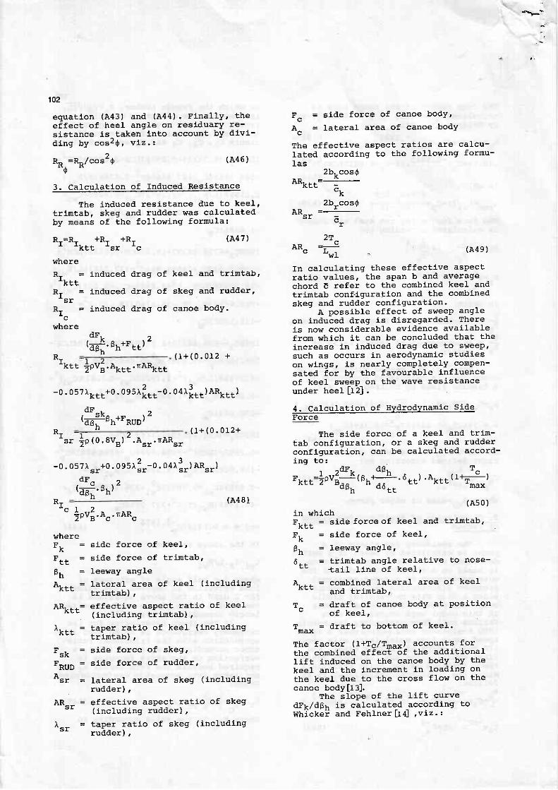
-]ovl.eo... nanu*
-0. 057trkf t+0. oes.r i t r -0. o4r i t t ) AR:.r t )
o ! ., s K ^ , -t ;7-PhTr Frrh/
102
equatlon (A43) and (A44) . Finally. theeffect of heel angl-e on resldualy re-sistance is taken j.nto account by divj--d ing by cos?q, v12. ,
R^ =R- /cos 'O (A46)0
3. calculatlon of Induced Resistance
The induceal resistance due to keel'tr imtab. skeg and rualder was calculatedby means of the following formula:
R,=R- +Rr +Rr_ ' k t t _s r _c
where
R- = induced drag of keel and tr imtab,,< EL
R- = Lnduced draq of skeg
Rr = induced drag of canoe_ c
wheredF.
r----.1! a +n tz' d 8 n ' " h - t t '
Fc = sii le force of canoe bodY,
Ac = Iateral area of canoe body
The effective aspect ratios are calcu-lated according to the following formu-las
2bkcos0AR,_,-=-
-k
2b-cos0lP =----:-
- r
AR. - (A49 )
In calculat ing these effect ive aspectrat lo values. the sPan b and averagechord E refer to the combined keel ' andtr intab configuration and the combinedskeg and rudder configuratl 'on.
A posslble effect of sweep angleon incluced drag is disregarded. Thereis now considerable evidence avai lablefron lrhich i- t can be concluded that theincrease in induced drag due to sweep.such as occurs in aerodynamlc studleson wings, Ls nearly completely compen-sated for by the favourable inf luenceof keel gwe_ep- on the wave resistanceunder heel Lt 2l '
4. calculat ion of Hydrodynanic sideIorce
The side force of a keel and tr im-tab configuratlon, or a skeq and rudderconfiguration, can be calculaled accord-ingi to:
, "dr,. dBL T^Fkrt=;ov;i ( Bnf . 6 tr) .Aktt ( r+r-)
"Ph " " t t
(As0 )in whlchFk t t = s i de fo rceo f kee l and t r im tab '
Fk = s l de f o r ce o f kee l ,
Fh = leeway angle '
6-- = tr imtab angle relat ive to nose-ta i l l i ne o f kee l ,
A. . . = comblned lateraf area of keelKcE
and t r im tab ,
T^ = draft of canoe body at Posit lon" o f k e e l ,
Tmax = draft to bottom of keel '
The factor ( l+Tc,/Tmax) accounts forthe conbined effecE of the addit ionall i f t tnaluced on the canoe body by thekeel and the lncrenent in loadlng onthe keel due to the cross f low on thecanoe body [t : ] .
The slope of the l l f t curvedFk /dBh i s ca l cu la ted acco ra l i ng t oWh]cke i and Feh lne r l t d , v i z . t
(A47 )
and rudder,
body.
side force of kee1,
sl-de force of trimtab '
leeway angle
lateral area of keel (includinglt r i r tab) ,
effective aspect ratio of keel(including triJltab),
taper ratio of keel (includlngt r ln tab) ,
side force of skeg,
side force of rudder,
lateral area of skeg (inqludinqrudder ) ,
effective aspect ratj-o of skeq/ ; - ^ r , , r i - ^ ? ! t n ^ 6 f \
taper ratlo of skeg (includingrudder) ,
( 1 + ( 0 . 0 1 2 +
a-'r. . ] o t o , a u " t 2 . A " r . n A R " , ( r + ( 0 . 0 r 2 +
-0.057) .sr+0. ogSr l r -0. Oal3. r ) anr . )dF^ )
' d p h . " h ,(A481
" |ovfr'4". na*"
. I
where
- t t
A R . . . =K t t
,< Et
. RUD
"'-s!
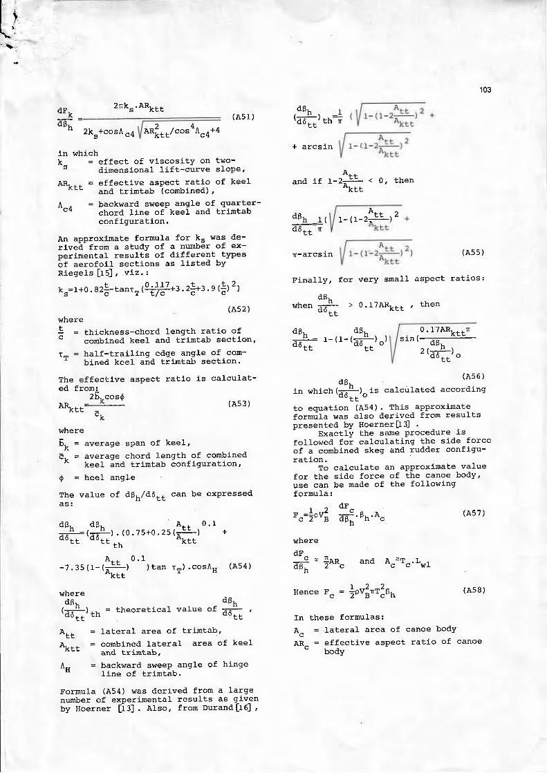
Ll lt - l
103
2k +cos^ ̂ / anf,r.,l.o.a,'t"n+a
in whichk - = e f f ec t o f v i scos i t y on two -
" di.mensional l- i f t-curve slope,
AR, - , , = e f f ec t i ve aspec t r a t i o o f kee land tr imtab ( conbined) ,
A-, = backvJard sweeP angle of quarter-c'r chord l ine of keel and tr intab
conflguration.
An approxirate formula for ks was de-rivei- from a study of a numb6r of ex-perlmental results of dif ferent typeso f ae ro fo i l sec t i ons as t i s t ed bYR iege l s [ r 5 ] , v l z . :
+ n r l ? + t )ks=l+0. 82cj - tanr r ( \ r? : -+3 .2:+3. 9 ( ; ) - )
(As2)
thickness-chord lenqth ratio ofconbined keel and trimtab section'
hatf-trail ing edqe anqle of com-bined keel and trimtab sectlon.
The effective aspeqt ratio is calculat-ed fron:
26 , -cos0AR. =____!_ (A53)
nrhere
E. = averaqe span o f kee l ,K -
E,. = average chord length of conbined^
keel and tr imtab configuration'
0 = heel angle
The value of dBh,/d6tt can be exPreEseda s :
dFt
o F h( A 5 1 )
(A54 )
6Bh
*" t t
d6r. r' d d r r ' t h r
. f arcsln
and i f 1-2;-: < 0, thenK E E
dg*_---:.i_:: \d6t t r
whereE
Att = lateral area of tr ir l tab'
A r * , = co rnb ined l a te ra l a rea o f kee land tr imtab,
l- = back!,rard sweep angle of hinge" I i ne o f t r im tab .
Fornula (A54) vas derived from a largenumber of experjrental results as g-j.v-enby Hoe rne r [ i : ] . a r so , f r on Du rand l r5 ] ,
Flnally' for very small aspect ratios:
dB,when =-#- > 0. f /ARr- , - ' Lnen
o o ,
dB, dB,.
atft='-tt-tuntr"r0 . l TAR] r i n
d i n / - - - _
^ , * ' h ,, \ET]- ' 'OE E
dBr . (A56 )
in which (; ;L)^ is calcutated according- " t t -
t o equa t i on (A54 ) . Th i s app rox ima teformrj la was also derived from resultspresented by goerner[3]
Exactly the same Procedure is
fol lowed for calculat ing the side forceof a cornbined skeg and rudder configu-rat10n.
To calculate an apProximate valuefor the side force of the canoe body,use can be made of the fol lowinqformula:
^ o!r ^ = { o v j ; 7 9 . e n . a ^ ( A s 7 )
where
a& 7'^c' n
Hence Fc = joufl"tl nn
In these formulas:
Ac = lateral area of
ARc = effect ive asPectoocly
(As5)
(AsB)
canoe body
ratio of canoe
dBr. dBr.d 6 r r ' d 6 r t '
A . . 0 , 1. ( 0 . 7 5 + 0 . 2 s ( i : ! - ) +. KEE
t n
A . . 0 , 1- 7 . 3 5 ( 1 - ( - - ! L ) ) t a n r T ) . c o s ^ H
wheredBr-
(;rL) *" = theoretical value of- " t t - "
2rTks.ARktt