The Wings3D Handbook - Oortman3D · 1 The Wings3D Handbook (Wings3D 1.0) Chapters Planned Chapters...
29
1 The Wings3D Handbook (Wings3D 1.0) Chapters Planned Chapters Started Chapters Mostly Completed 1. “Getting Started” “Getting Started” 2. “Your First Model” 3. “Materials” “Materials” 4. “Lights” 5. “YafRay” “YafRay” 6. “Tweak Mode” 7. “UV Mapping” Dated: 12-May-09 By: Oortman3D The cover page will be changed when the Wings3D Handbook is near completion.
Transcript of The Wings3D Handbook - Oortman3D · 1 The Wings3D Handbook (Wings3D 1.0) Chapters Planned Chapters...

1
The
Wings3DHandbook
(Wings3D 1.0)
Chapters Planned Chapters Started Chapters Mostly Completed
1. “Getting Started” “Getting Started”
2. “Your First Model”
3. “Materials” “Materials”
4. “Lights”
5. “YafRay” “YafRay”
6. “Tweak Mode”
7. “UV Mapping”
Dated: 12-May-09
By: Oortman3D
The cover page will be changed when the Wings3D Handbook is near completion.
2
Chapter 1
Getting StartedThis Handbook assumes that you know how to install Wings3D and that you are currently looking at
the GUI (Graphical User Interface) with a blank stare on your face thinking now what?...
When reading this handbook note the following: Bold font is used for hot-keys.
Italic font is used for Menu commands and the > symbol is used between a series of commands.
All Commands are surrounded by brackets [command] in order to separate them and make them stand out.
The following abbreviations are used for Mouse Button commands: [LMB] Left Mouse Button, [MMB] Middle Mouse Button, [RMB] Right Mouse Button.
Menu Bar Commands are selected by clicking with the [LMB]. Context Sensitive Menu [RMB] Commands are selected by clicking with [LMB], [MMB], [RMB], or even [Alt+Click]. Watch the Information Line for available command options.
Within menus, “Enable” means a check mark is present and “Disable” means a check mark is NOT present.
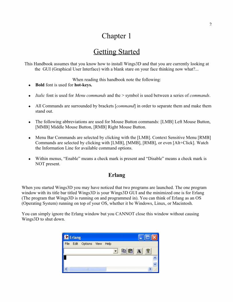
Erlang
When you started Wings3D you may have noticed that two programs are launched. The one program window with its title bar titled Wings3D is your Wings3D GUI and the minimized one is for Erlang (The program that Wings3D is running on and programmed in). You can think of Erlang as an OS (Operating System) running on top of your OS, whether it be Windows, Linux, or Macintosh.
You can simply ignore the Erlang window but you CANNOT close this window without causing Wings3D to shut down.
3
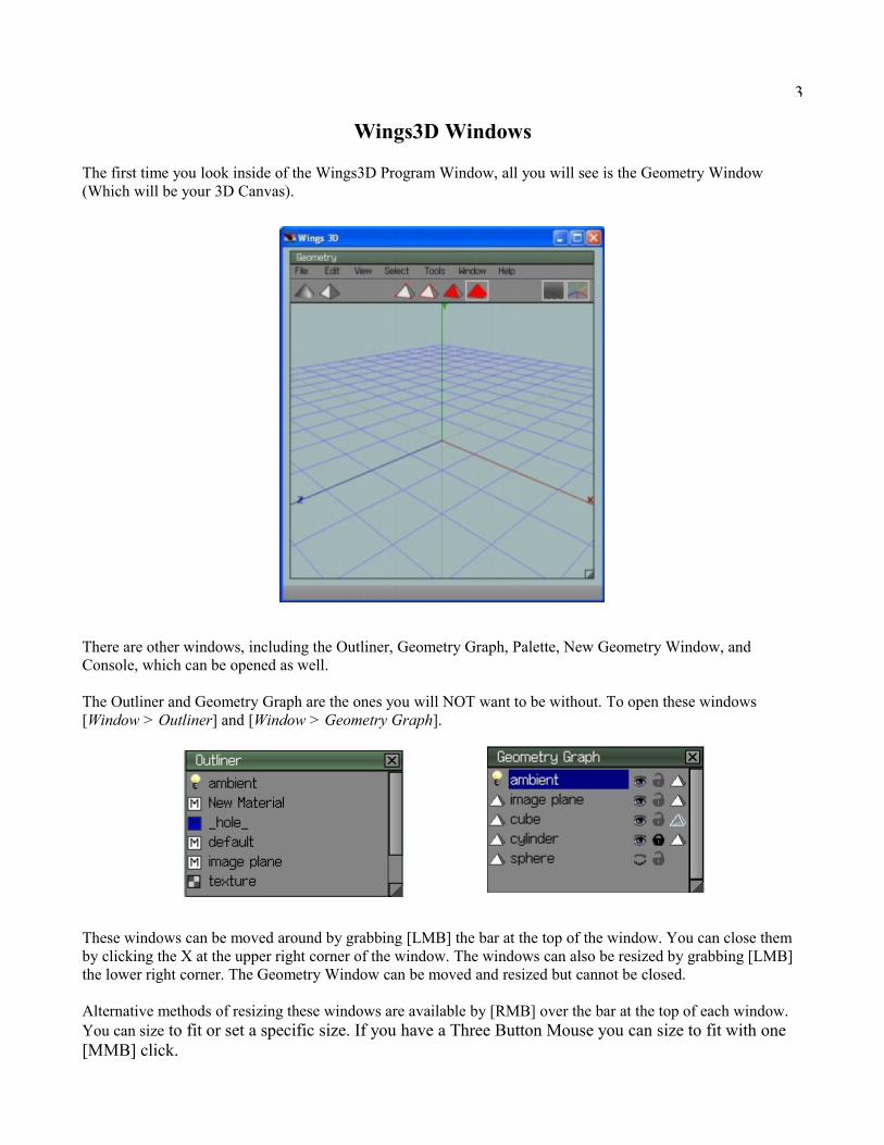
Wings3D Windows
The first time you look inside of the Wings3D Program Window, all you will see is the Geometry Window (Which will be your 3D Canvas).
There are other windows, including the Outliner, Geometry Graph, Palette, New Geometry Window, and Console, which can be opened as well.
The Outliner and Geometry Graph are the ones you will NOT want to be without. To open these windows [Window > Outliner] and [Window > Geometry Graph].
These windows can be moved around by grabbing [LMB] the bar at the top of the window. You can close them by clicking the X at the upper right corner of the window. The windows can also be resized by grabbing [LMB] the lower right corner. The Geometry Window can be moved and resized but cannot be closed.
Alternative methods of resizing these windows are available by [RMB] over the bar at the top of each window. You can size to fit or set a specific size. If you have a Three Button Mouse you can size to fit with one [MMB] click.

4
The ability to set a specific size for the Geometry window is helpful if you want to control your field of view at a specific image size when you are ready to Render (Export your model/scene as a 2D Image).
The Geometry Window has the added option of Hiding/Showing the Toolbar. The next time you start Wings3D the window sizes and positions will be the same as you left them. The Camera axis view will however be reset to the default view. If you want to keep an important camera axis view for the future, you can save the View [View > Saved Views: > Save Options Box > Enter a View Name > OK]. You can even save files containing only Saved Views for use as templates to be imported using the Merge command [File > Merge].
User Preferences
As is the case with most programs you will need to set your User Preferences [Edit > Preferences].
General PreferencesUnder the General Tab, you may want to change the setting for Selection Color from Red to a Brighter color to enhance the visibility of selected entities.
Another handy feature is Smart Highlighting which when enabled allows you to select either Vertex, Edges, or Faces by hovering over them instead of having to preselect the selection mode. Beginners may want to leave this feature disabled. Smart Highlighting is most useful when using the [Tools > Tweak] command.
Enabling “Force Axis-Aligned Ortho” will temporarily switch to Ortho mode when you View Along any of the Axis [X],[Y],[Z], etc.

5
Camera Preferences
Under the Camera Tab, you will need to set the number of Mouse Buttons depending on what type of mouse you have.
A Three Button Scroll Mouse is preferred when using Wings3D but an old Three Button Mouse or Two Button Mouse will work quite well.
You can also set the Camera Mode to various settings.
If you have a Three Button Scroll Mouse you will want to use Wings3D Camera Mode.
If you have an old Three Button Mouse or Two Button Mouse set the Camera Mode to Nendo.

6
Advanced Preferences Under the Advanced Tab, make sure that “Use Highlight as Temporary Selection” is enabled so that the Highlight Aim [A] function is available.
For Highlight Aim Targets enable both “Selected Geometry” and “Unselected Geometry”.
Constraints Preferences
Under the Constraints Tab, you can change the various distance, scale and rotation controls to suit your needs. Deleting the value or entering '0' will reset the constraint to the Wings3d default setting.
7
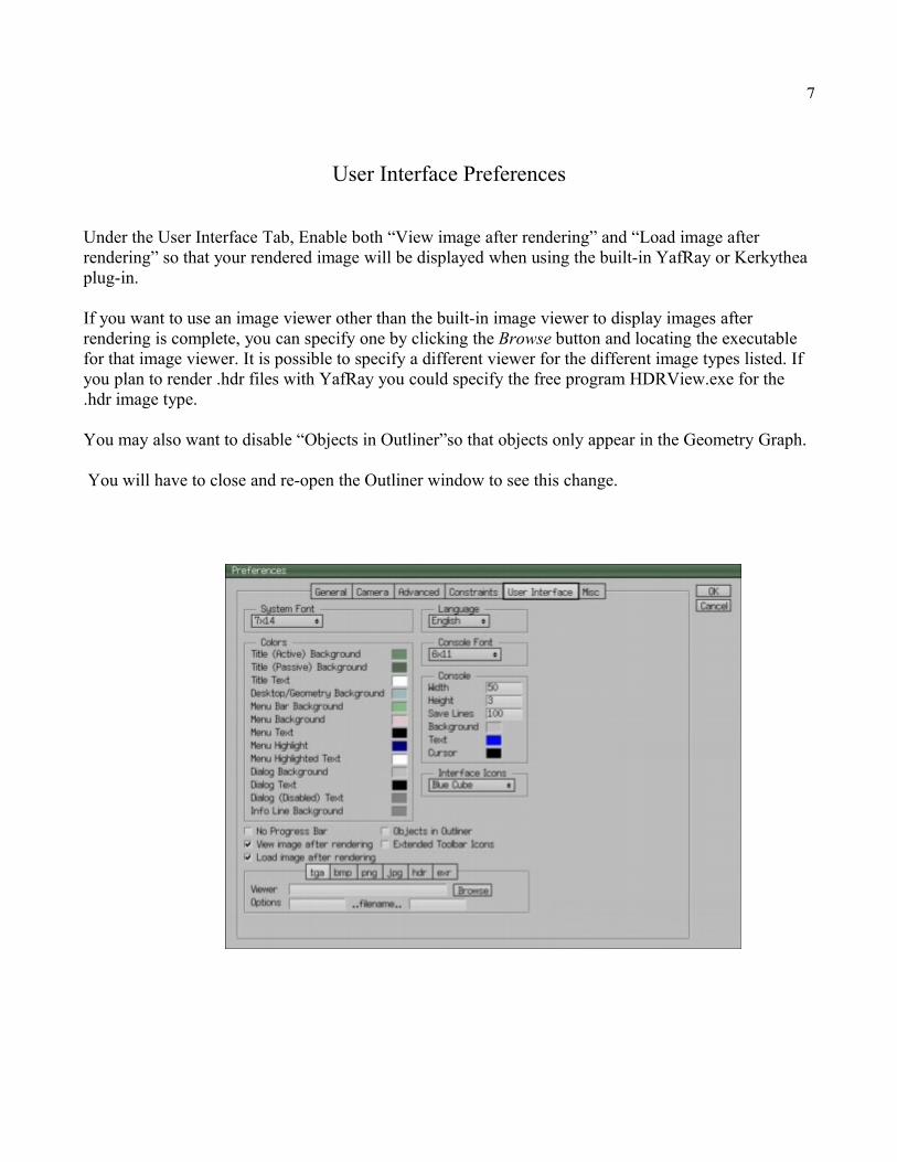
User Interface Preferences
Under the User Interface Tab, Enable both “View image after rendering” and “Load image after rendering” so that your rendered image will be displayed when using the built-in YafRay or Kerkythea plug-in.
If you want to use an image viewer other than the built-in image viewer to display images after rendering is complete, you can specify one by clicking the Browse button and locating the executable for that image viewer. It is possible to specify a different viewer for the different image types listed. If you plan to render .hdr files with YafRay you could specify the free program HDRView.exe for the .hdr image type.
You may also want to disable “Objects in Outliner”so that objects only appear in the Geometry Graph.
You will have to close and re-open the Outliner window to see this change.
8
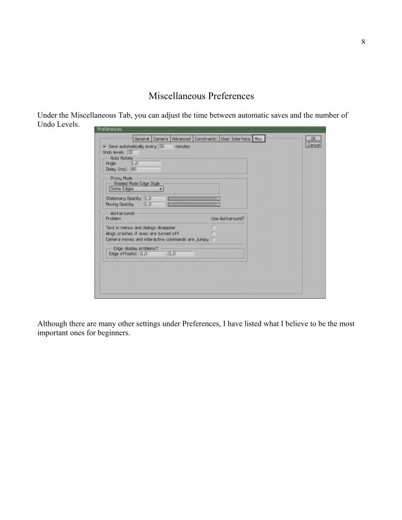
Miscellaneous Preferences
Under the Miscellaneous Tab, you can adjust the time between automatic saves and the number of Undo Levels.
Although there are many other settings under Preferences, I have listed what I believe to be the most important ones for beginners.
9
Navigation
The method for activating the Camera (Allows you to Tumble, Zoom, Pan) in the Geometry Window depends on whether you have a two or three button mouse (Middle Mouse Button assumed to be set to its Default Setting in your Operating System's Settings. Special MMB settings may prevent its use.).
If you have either a Three Button Scroll Mouse (Wings3D Camera Mode) or old Three Button Mouse (Nendo Camera Mode) you simply click the [MMB] to activate the Camera.
If you have a Two Button Mouse (Nendo Camera Mode) you will need to hold down the Ctrl Key at the same time you click your [RMB] to activate the Camera.
After the Camera is activated, moving the mouse allows you to tumble the model/scene in 3D space.
The method for Zooming the Camera, after the Camera is activated, is dependent on whether you have a Three Button Scroll Mouse, old Three Button Mouse, or Two Button Mouse.
With a Three Button Scroll Mouse (Wings3D Camera Mode) you can use the Scroll Wheel to zoom in and out. You can also Hold down the Alt Key while rolling the wheel for a smaller zoom factor. The Scroll Wheel Zoom Factor and Alternate Zoom Factor can be adjusted in the User Preferences [Edit > Preferences > Camera Preferences].
With a Three Button Mouse (Nendo Camera Mode) you hold down the [RMB] while moving the mouse forward and backward.
With a Two Button Mouse (Nendo Camera Mode) zooming is accomplished by holding down the [RMB] while moving the mouse forward and backward.
The method for Panning the Camera, after the Camera is activated, depends on the Camera Mode Setting.
With Wings3D Camera Mode (Three Button Scroll Mouse) you Pan by simply holding down the [MMB] while moving the mouse in various directions.
With Nendo Camera Mode Panning is made possible by hitting the [Q] key and then moving the mouse in various directions.
The Pan Speed / Step Increment can be adjusted under the Camera Tab of Preferences [Edit > Preferences > Camera Preferences]. It is also possible to Pan using the Arrow Keys of your Keyboard.
An additional feature which is very helpful is the Highlight Aim feature. Simply mouseover highlight or select a Vertex, Edge, Face, or Body (Object) and [View > Highlight Aim] [A] and the selected entity/entities becomes the central point of focus. Highlighted items take the primary focus over selected items. “Use Highlight as Temporary Selection” must be enabled under Advanced Preferences.
In order to get back to the default camera view simply [View > Reset View] [R].
10
The GUI
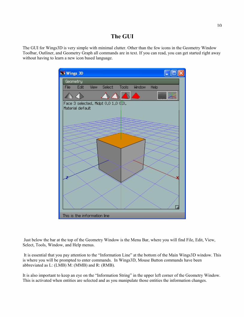
The GUI for Wings3D is very simple with minimal clutter. Other than the few icons in the Geometry Window Toolbar, Outliner, and Geometry Graph all commands are in text. If you can read, you can get started right away without having to learn a new icon based language.
Just below the bar at the top of the Geometry Window is the Menu Bar, where you will find File, Edit, View, Select, Tools, Window, and Help menus.
It is essential that you pay attention to the “Information Line” at the bottom of the Main Wings3D window. This is where you will be prompted to enter commands. In Wings3D, Mouse Button commands have been abbreviated as L: (LMB) M: (MMB) and R: (RMB).
It is also important to keep an eye on the “Information String” in the upper left corner of the Geometry Window. This is activated when entities are selected and as you manipulate those entities the information changes.

11
Geometry Window Toolbar
Just below the Menu Bar, is the Geometry Window Toolbar. In the middle of this Toolbar, you will see four icons for selecting different modes.
From left to right they are Vertex Mode [V], Edge Mode [E], Face Mode [F], and Body (Object) Mode [B]. If you are wondering where all the modeling commands are, they are just a [RMB] click away. Depending on which mode you are in, different commands will show up when you click the [RMB].
When you are ready to model you will need to start with a Primitive (Basic Shape). These will show up when you click the [RMB] while no entities are selected [Space-bar].
On the left side of the Geometry Window Toolbar are two icons.
The one to the far left will let you switch between Flat Shading and Smooth Shading mode. The Tab Key [Tab] can also be used to switch the mode between Flat and Smooth Shading. While in Smooth Preview Mode [Shift-Tab], clicking the icon or hitting the Tab Key [Tab] allows you to see both the smoothed model and its control cage.
The second icon from the left will let you switch between Perspective and Orthographic viewing mode [O].
On the right side of the Geometry Window Toolbar are icons for switching On/Off the Ground Plane Grid and the Axes.
It is best to leave the Axes visible, since this helps you to know where X,Y and Z are at all times.
12
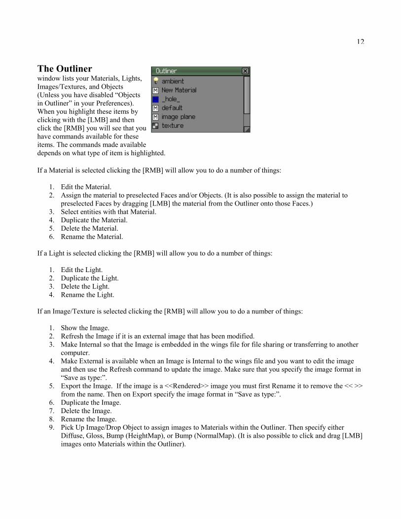
The Outliner window lists your Materials, Lights, Images/Textures, and Objects (Unless you have disabled “Objects in Outliner” in your Preferences). When you highlight these items by clicking with the [LMB] and then click the [RMB] you will see that you have commands available for these items. The commands made available depends on what type of item is highlighted.
If a Material is selected clicking the [RMB] will allow you to do a number of things:
1. Edit the Material.2. Assign the material to preselected Faces and/or Objects. (It is also possible to assign the material to
preselected Faces by dragging [LMB] the material from the Outliner onto those Faces.)3. Select entities with that Material.4. Duplicate the Material.5. Delete the Material.6. Rename the Material.
If a Light is selected clicking the [RMB] will allow you to do a number of things:
1. Edit the Light.2. Duplicate the Light.3. Delete the Light.4. Rename the Light.
If an Image/Texture is selected clicking the [RMB] will allow you to do a number of things:
1. Show the Image.2. Refresh the Image if it is an external image that has been modified.3. Make Internal so that the Image is embedded in the wings file for file sharing or transferring to another
computer.4. Make External is available when an Image is Internal to the wings file and you want to edit the image
and then use the Refresh command to update the image. Make sure that you specify the image format in “Save as type:”.
5. Export the Image. If the image is a <<Rendered>> image you must first Rename it to remove the << >> from the name. Then on Export specify the image format in “Save as type:”.
6. Duplicate the Image.7. Delete the Image.8. Rename the Image.9. Pick Up Image/Drop Object to assign images to Materials within the Outliner. Then specify either
Diffuse, Gloss, Bump (HeightMap), or Bump (NormalMap). (It is also possible to click and drag [LMB] images onto Materials within the Outliner).

13
The Geometry Graph window lists your Objects, Lights, and Image Planes. When you highlight these items by clicking with the [LMB] and then click the [RMB] you will see that you have commands available for these items. You can Duplicate, Delete, or Rename these items.
In this window you have the added ability to Hide/Show (Eye icon), Lock/Unlock (Lock icon), and switch between Shaded/Wireframe (Pyramid icon - next to Lock icon) any items in this window by clicking the [LMB]. When you click the [RMB] while the cursor is over one of these icons you can Hide all other Objects, Lock all other Objects, and/or Wireframe all other Objects. If you click the [RMB] over Geometry icons (Pyramid or Light icon next to an item description) you select all Objects. Click [RMB] again and the item by the cursor is selected and all others are deselected.
Menu Bar
As mentioned earlier, at the top of the Geometry Window is the Menu Bar, where you will find File, Edit, View, Select, Tools, Window, and Help menus.
Next to some items within these menus you will see a small box. Clicking the box will give you additional options for those commands. When you highlight menu items a description of each command will show up on the “Information Line” at the bottom of the Main Wings3D Program Window.
I have listed hot-keys (keyboard short-cuts) for some of the menu commands. Any command that appears in a menu can be assigned a hot-key. Make sure that Caps Lock is turned off.
Simply highlight the menu command you want hot-keyed, then press the [Insert] or [/] key followed by the key you want to assign the command to.
To delete a custom hot-key highlight the command, then press the [Del] or [\] key.
Be careful not to assign hot-keys using existing short-cut keys. You can find a full list of Defined hot-keys under the Help menu.
One hot-key which you will use often but does not show up within the Menu Bar menus is the Backspace key [Bksp], which is used to delete selected items. The Delete key [Del] can be used to give the same results as the Backspace key.
14
File Menu
Under the File menu you will find, among others, the following important commands:
1. New = Start a new File.2. Open = Open an existing File.3. Merge = Merge another wings file into your current file. This is useful when you want to use Materials,
Lighting Environments, or Saved Views from a library of presets. Note that any Saved Views in the current file will be lost when you Merge in the new file/files.
4. Save = Save the File.5. Save As = Save the File as a new File name.6. Save Selected = Save selected items as a new File name.7. Save Unused Materials = Enable to Include unused Materials when Saving a .wings file. Great for
saving a file containing only materials for a library of material presets to Merge into future files. 8. Import = Import a variety of 3D file formats as well as .AI and .PS (Adobe or Inkscape) 2D shapes.9. Export = Export a variety of 3D and 2D file formats. (.obj is preferred over .3ds)10. Export Selected = Export selected items as a variety of 3D and 2D file formats.11. Import Image = Used to import images for use as textures.12. Render = Export a 2D image of your 3D scene using a variety of Rendering Programs.
Edit Menu
Under the Edit menu you will find, among others, the following important commands:
1. Undo/Redo [Ctrl+Z] = Undo/Redo last command.2. Undo [Ctrl+Alt+Z] = Undo a number of previous commands.3. Redo [Ctrl+Shft+Z] =Redo a number of previous Undo commands.4. Preferences = Setup user Preferences.5. Plug-in Manager = Enable and Disable Plug-ins.6. Plug-in Preferences = Setup installed Plug-ins.
View Menu
Under the View menu you will find, among others, the following important commands:
1. Toggle Wireframe [W] = Toggle Wireframe on/off.2. Quick Smoothed Preview [Shift+Tab] = Preview model with single subdivision.3. Show Saved BB = Show the Saved Bounding Box (See Tools Menu).4. Reset View [R] = Reset Camera to default view.5. Aim [A] = Center Camera focus on selected item/items.6. Frame [Shift+A] = Center Camera focus on all items in scene.7. Orthographic View [O] = Switch between Orthographic and Perspective View.8. Saved Views = Save the current Camera view.9. Camera Settings = Adjust Camera Clipping Planes.10. Scene Lights = Light model/scene with lights in scene. If no lights are present the model will turn black
as you would expect with no lighting. This should be left disabled in most cases. Having Scene Lights enabled is most useful if you are setting up lights for rendering.
11. One Light/Two Lights = Set the number of Work Lights. This also affects OpenGL Renders.12. View Along = View the model along the specified Axis. Hot-keys are as follows:
[X] X Axis,[Y] Y Axis,[Z] Z Axis,[Shift+X] -X Axis,[Shift+Y] -Y Axis,[Shift+Z] -Z Axis.

15
13. Auto Rotate [U] = Spin the Model/Scene, - To Slow Down, + To Speed Up.
Select Menu
Under the Select menu you will find, among others, the following important commands:
1. Deselect [Space] = Clear selected items.2. Similar [I] = Select items similar to already selected items.3. Edge Loop [L] = Select adjacent edges to form a loop of edges.4. Edge Ring [G] = Select parallel edges to form a ring of edges.5. Inverse [Ctrl+Shift+I] = Inverse Selection to select the unselected and deselect the selected items.6. Store Selection = Store selected items as a group named “StoredSelection”. It is possible to store a
separate group within each of the four selection modes (Vert, Edge, Face, Body).7. Recall Selection = Recall items saved as group “StoredSelection”. The type of Items recalled will
depend on the active selection mode (Vert, Edge, Face, Body).8. New Group = Create a Named Group of items.9. Delete Group = Delete a Named Group.10. Select Group = Select from list of Named Groups.
Tools Menu
Under the Tools menu you will find, among others, the following important commands:
1. Align = Align two or more entities along various axes options.2. Center = Center one or more entities along various axes options.3. Save Bounding Box = Creates a Scaling/Placement Measuring Tool.4. Scale to Saved Bounding Box = Scale to dimensions of Bounding Box along various axes options.5. Scale to Saved Bounding Box Proportionally = Scale to dimensions of Bounding Box along various axes
options, while maintaining Proportions.6. Move to Saved Bounding Box = Move to dimensions of Bounding Box along various axes options.7. Virtual Mirror Create = Mirror object about a selected face/plane. Used for symmetrical objects.
Changes made to original side of mirror plane produces same changes to virtual geometry on opposite side of mirror plane and vice versa.
8. Virtual Mirror Break = End Virtual Mirror and delete mirrored virtual geometry.9. Virtual Mirror Freeze = End Virtual Mirror and preserve mirrored virtual geometry.10. Put on Ground = Move selected objects placing them on ground plane.11. Connect = Draw edges connecting any combination of edges and/or vertex.12. Snap Image = Apply Textures (Images loaded with [File > Import Image]) to selected faces. Used while
in Face Mode. For best results apply textures while aligned to faces along each axes separately, whether X,Y,Z.
13. Tweak = Enter advanced geometry editing mode. Most often used for Organic modeling. To exit Tweak mode hit the ESC key.
16
Window Menu
Under the Window menu you will find, among others, the following important commands:
1. Outliner = Open Outliner Window2. Geometry Graph = Open Geometry Graph Window3. Palette = Open Palette Window.4. New Geometry Window = Open additional Geometry Windows.5. UV Editor Window = Open the UV Editor Window.
Help Menu
Under the Help menu you will find several helpful bits of information. Here you will find a listing of all the predefined hot-keys, as well as user-defined hot-keys.
Context Sensitive Menus
What makes modeling with Wings3D so efficient is the use of context sensitive pop-up menus which are accessed by right clicking [RMB] in the Geometry Window.
There are five context sensitive menus: Primitives Menu. (Available when no entities are selected [Space-bar]) Vertex Menu. Edge Menu. Face Menu. Object Menu.
Depending on what type of entity (Vertex, Edge, Face, Body) is selected [LMB], different menus will pop-up with commands that can be used for that specific type of entity. Next to some items within these menus you will see a small box. Clicking the box will give you additional options for those commands.
As you use different commands to manipulate the geometry of your 3D model keep an eye on the “Information Line” at the bottom of the Main Wings3D Program Window for prompts.
You will also want to keep an eye on the “Information String” in the upper left corner of the Geometry Window for information on the entities you have selected. When you see a changing D (Distance) or % (Percentage) value, you can hit the Tab key [Tab] and enter a specific numeric value or a mathematical expression (12/4, 2*6, 5+1, 4-2, etc.).
Holding down either the Shift, Ctrl, or Shift-Ctrl keys adds Distance or Percentage Constraints depending on the active command: Shift = 1 or 100%, Ctrl = 0.1 or 10%, Shift-Ctrl = 0.01 or 1% (Assuming Constraints are at Default Settings in Preferences [Edit > Preferences > Constraints]).
Within the various context sensitive menus you will notice a command called [Absolute Commands], which will allow you to enter specific numeric values.
These options along with the use of Bounding Boxes will help you to build a 3D model to scale. You must however remember that Wings3D is not intended to be used as a precision manufacturing design tool.
17
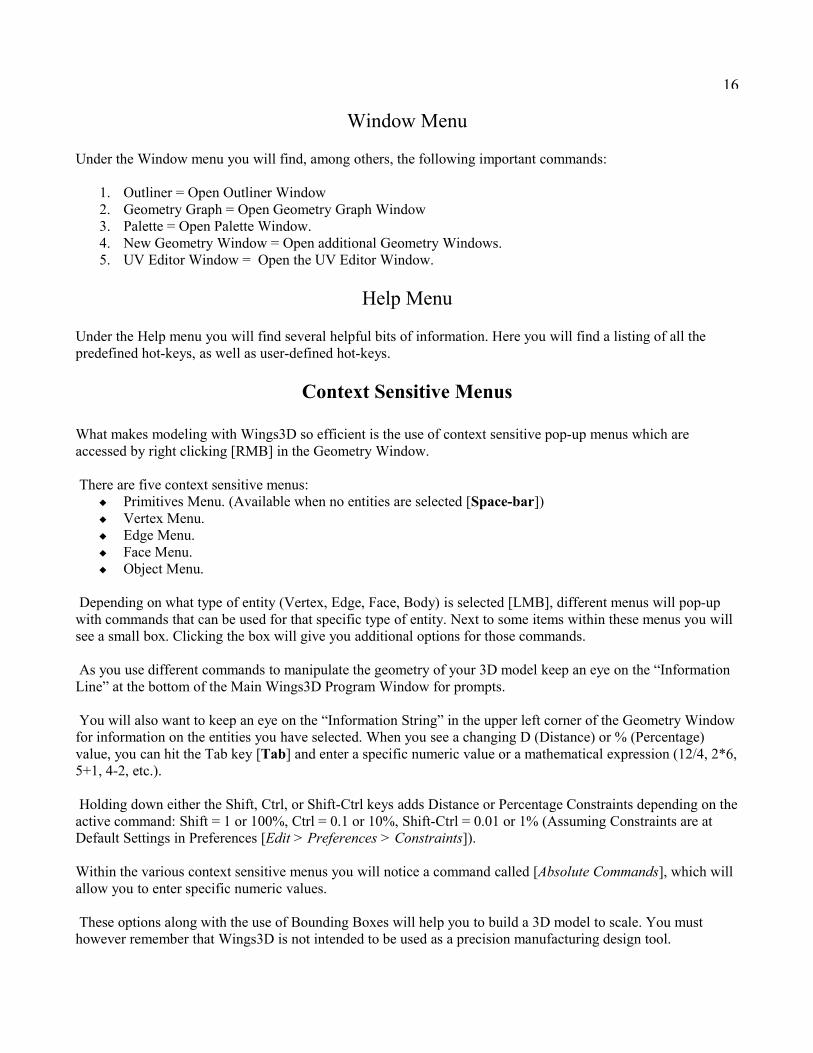
Selecting Entities
As previously mentioned, different context sensitive menus appear depending on which entity selection mode is active. No matter which mode is selected entities are selected by clicking with the [LMB]. Clicking the same entity again will cause it to be deselected.
Multiple entities, including those hidden by geometry, can be selected by clicking and dragging a window across an area. These entities do not have to be completely within the window.
Holding down the Ctrl key will allow multiple entities to be deselected. These entities do not have to be completely within the window.
Holding down the Shift key allows you to window select only those entities that are completely within that window.
Holding down the Shift and Ctrl keys and selecting a window allows only those entities that are completely within that window to be deselected.
Another method of multiple selection is available by clicking with the [LMB] and keeping the button pressed as you paint over additional entities of that type. Multiple entities can be deselected by the same method.
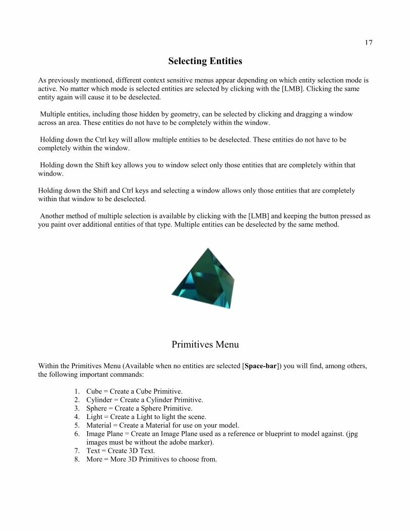
Primitives Menu
Within the Primitives Menu (Available when no entities are selected [Space-bar]) you will find, among others, the following important commands:
1. Cube = Create a Cube Primitive.2. Cylinder = Create a Cylinder Primitive.3. Sphere = Create a Sphere Primitive.4. Light = Create a Light to light the scene.5. Material = Create a Material for use on your model.6. Image Plane = Create an Image Plane used as a reference or blueprint to model against. (jpg
images must be without the adobe marker).7. Text = Create 3D Text.8. More = More 3D Primitives to choose from.

18
Vertex Menu
Within the Vertex Menu you will find, among others, the following important commands:
1. Move = Move Vertex2. Rotate = Rotate Vertex3. Scale Uniform = Scale Vertex Uniformly.4. Scale Axis = Scale Vertex on either X,Y,or Z axes.5. Scale Radial = Radial Scale Vertex.6. Absolute Commands = Access Absolute Commands.7. Extrude = Extrude from Vertex.8. Flatten = Flatten two or more Vertex.9. Connect [C] = Connect two or more Vertex.10. Bevel = Create Flat surface at Vertex.11. Dissolve [Del]= Delete selected Vertex.12. Deform = Access Deform tools including: Crumple, Inflate, Inflate Cylindrical, Taper, Twist,
Torque and Shear.13. Vertex Color = Set color of selected Vertex.
19
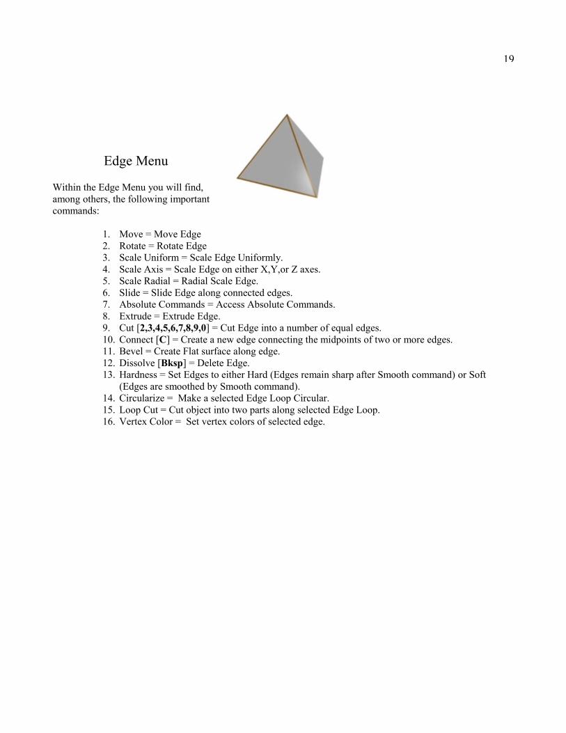
Edge Menu
Within the Edge Menu you will find, among others, the following important commands:
1. Move = Move Edge2. Rotate = Rotate Edge3. Scale Uniform = Scale Edge Uniformly.4. Scale Axis = Scale Edge on either X,Y,or Z axes.5. Scale Radial = Radial Scale Edge.6. Slide = Slide Edge along connected edges.7. Absolute Commands = Access Absolute Commands.8. Extrude = Extrude Edge.9. Cut [2,3,4,5,6,7,8,9,0] = Cut Edge into a number of equal edges.10. Connect [C] = Create a new edge connecting the midpoints of two or more edges.11. Bevel = Create Flat surface along edge.12. Dissolve [Bksp] = Delete Edge.13. Hardness = Set Edges to either Hard (Edges remain sharp after Smooth command) or Soft
(Edges are smoothed by Smooth command).14. Circularize = Make a selected Edge Loop Circular.15. Loop Cut = Cut object into two parts along selected Edge Loop.16. Vertex Color = Set vertex colors of selected edge.

20
Face Menu
Within the Face Menu you will find, among others, the following important commands:
1. Move = Move Face2. Rotate = Rotate Face3. Scale Uniform = Scale Face Uniformly.4. Scale Axis = Scale Face on either X,Y,or Z axes.5. Scale Radial = Radial Scale Face.6. Absolute Commands = Access Absolute Commands.7. Extrude = Extrude Faces separately.8. Extrude Region = Extrude Faces as a group.9. Extract = Extract a copy of the selected Face/Faces.10. Sweep = Extrude Faces with Greater Control. Good for Organic Modeling. (Great for Tree
Branches, Horns, Ribbons, etc.) Use with [Shift+D] for a quick spiral.11. Flatten = Flatten Face/Faces on specified axes.12. Inset = [LMB]Create Face inside selected Face/Faces. [RMB] Inset a group/region of Faces.
[MMB] Offset a group/region of Faces.13. Intrude = Carve out interior of object with selected faces becoming openings. (Great for carving
out inside of Vases, Wine Bottles, etc.)14. Bevel = Round off edges of selected Face/Faces.15. Bridge = Build geometry between two selected Faces. This can also be used to cut holes in
objects.16. Bump = Create an Inset Face and Move the new Face along its Normal creating either a Bump
or dimple from selected Face/Faces. (Inset a group/region of Faces by selecting the Faces to be Inset, then doing an inverse selection [Select > Inverse], then Bump while holding down the Shift Key.)
17. Lift = Lift a Face using a selected edge as a hinge.18. Put On = Put one object onto another using the preselected Face as the mating surface.19. Mirror = Mirror Body/object about a preselected Face making mirrored geometry part of object.
Select Mirror command with [RMB] to create a separate Body/object.20. Dissolve [Bksp] = Delete Face.21. Tesselate = Break Selected Faces into Triangles, Quads, or Convert Triangles to Quads.22. Hide = Hide Selected Face.23. Vertex Color = Set vertex colors for selected Faces.24. UV Mapping = Create UV Map for selected Face/Faces.
21
Object Menu
Within the Object Menu you will find, among others, the following important commands:
1. Move = Move Object (Constrain to 1.0 step with Shift Key or 0.1 step with Ctrl Key or 0.01 step with Shift-Ctrl)
2. Rotate = Rotate Object (Constrain/Speed Up to 15 degree step with Shift Key or Slow Down to 1 degree step with Ctrl Key).
3. Scale Uniform = Scale Object Uniformly (Constrain to 100% step with Shift Key or 10% step with Ctrl Key or 1% step with Shift-Ctrl).
4. Scale Axis = Scale Object on either X,Y,or Z axes.5. Scale Radial = Radial Scale Object.6. Absolute Commands = Access Absolute Commands.7. Flip = Flip the Object about either X,Y,or Z axes.8. Invert = Turn Object inside-out or outside-in. (Flips Normals)9. Smooth [S] = Subdivide the Object to make smooth. Not to be used often, since this increases the
polygon count. It is better to use Quick Smoothed Preview [Shift-Tab] to see how the object will smooth. Your object can be smoothed during export if needed. It can also be smoothed during the rendering process.
10. Combine = Combine multiple Objects into a single Object.11. Separate = Separate combined Objects into individual Objects.12. Weld = Merge a pair of faces that are almost touching. The tolerance can be adjusted.13. Cleanup = Delete isolated vertices and/or short edges. The tolerance for edge length can be adjusted.14. Auto-Smooth = Set Edges hard or soft depending on the angle between faces. The angle setting can be
adjusted.15. Duplicate = Make a copy of the Object.16. Delete [Bksp] = Delete the object.17. Show All = Show All Faces. Used on an Object which has had some of its Faces previously Hidden.18. Vertex Color Mode/Material Mode = Toggle between Vertex and Material Color Modes.19. Object To Area Light = Convert an Object to an Area Light. This command can be used to turn a
cylinder into a fluorescent lamp or a lightbuld shaped object into a light bulb. Limit the number of faces in your object since each face is counted as another Area Light which increases rendering time. When using YafRay, if you want the material of a lightbulb shaped object to appear to emit light you must Extract the faces from the object just slightly away from the object. Then invert the Extracted object so that it shines back onto the lightbulb shaped object, which will reflect the light from the Extracted Area Light. The last step is to convert the Extracted object to an Area Light. Start with a Power setting of 80 for the newly created Area Light.
20. Colors to Materials/Materials to Colors = Convert Vertex Colors to Materials (Materials automatically created and shown in Outliner). Object with Materials applied, Colors are Converted to Vertex Colors.
21. Vertex Color = Apply Vertex Color to Object.22. UV Mapping = Create UV Map for the selected Object.
22
OpenGL Render
After you have created one of your Wings3D masterpieces you will want to share it with your friends and/or fellow Wingers. To do this you will need to Render, which is a way of exporting a 2D image of a 3D scene.
Before you Render, be sure to use the Cleanup command [Object Mode > RMB > Cleanup] to make sure there are no isolated vertices, which can on occasion produce artifacts on surfaces.
If you want to create a photo-realistic image of your scene you could try using the built in YafRay Plug-in, Kerkythea Plug-in or any other Plug-in designed for that purpose.
If all you need is a quick render to show off your modeling skills you can use the integrated OpenGL Rendering engine. The quality of the images produced is fairly good and Vertex Colors, Textures, Shadows, and Alpha Background are supported.
If you want to control the size of the rendered image, you will need to set the size of the Geometry Window (See the “Wings3D Windows” section of Chapter 1).
The first time you render click the small box next to OpenGL [File > Render > OpenGL] to adjust the OpenGL Render Options. The options available are as follows:
1. Quality = Different Quality levels to choose from.2. Sub-division Steps = Smooths all objects to the specified level (Use a setting of 1 or 2)3. Background Color = Sets the background color.4. Render Alpha Channel = Transparent background instead of color background.5. Render Shadows = Objects will cast shadows. (Disable if using two Work Lights with no other
lights present or when an Ambient Light is present).6. Render Self-Shadows = Enable when Bump Maps are used. (The Maps must have been applied
by using either the Snap Image Tool or UV Mapping).7. Image Window = When the render is completed it will be displayed in a window and will appear
in the Outliner Window. If this option is chosen, you can Export the image from the Outliner Window after you have Renamed the image, removing the << >> from the name.
8. File = Specify the file name so that the image will be written to a file instead of being displayed in a window and in the Outliner Window. Remember that this file will be overwritten without warning the next time you render.
Tip1: If you are seeing jagged edges in your rendered image, even when using the Super and Premium Quality Settings, you may need to Smooth Preview [Shift-Tab] the scene. Any changes to the size of the Geometry Window will require a new Smooth Preview.
Tip2: If your material seems bleached out try reducing the Specular setting of that material.
Tip3: Another setting that affects your rendered image is the Work Lights setting [View > One Light/Two Lights]. The One Light setting adds less shading to your objects.
Tip4: In order for lights in the scene to affect the render you must make Scene Lights active [View > Scene Lights].
23
Chapter Review
Always Remember to watch the Information Line and Information String.
Commands worth a second mention:
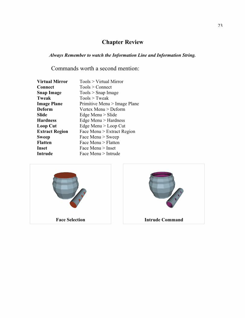
Virtual Mirror Tools > Virtual MirrorConnect Tools > ConnectSnap Image Tools > Snap ImageTweak Tools > TweakImage Plane Primitive Menu > Image PlaneDeform Vertex Menu > DeformSlide Edge Menu > SlideHardness Edge Menu > HardnessLoop Cut Edge Menu > Loop CutExtract Region Face Menu > Extract RegionSweep Face Menu > SweepFlatten Face Menu > FlattenInset Face Menu > InsetIntrude Face Menu > Intrude
Face Selection Intrude Command
24
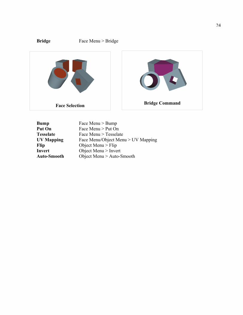
Bridge Face Menu > Bridge
Bump Face Menu > BumpPut On Face Menu > Put OnTesselate Face Menu > TesselateUV Mapping Face Menu/Object Menu > UV MappingFlip Object Menu > FlipInvert Object Menu > InvertAuto-Smooth Object Menu > Auto-Smooth
Face Selection Bridge Command
25
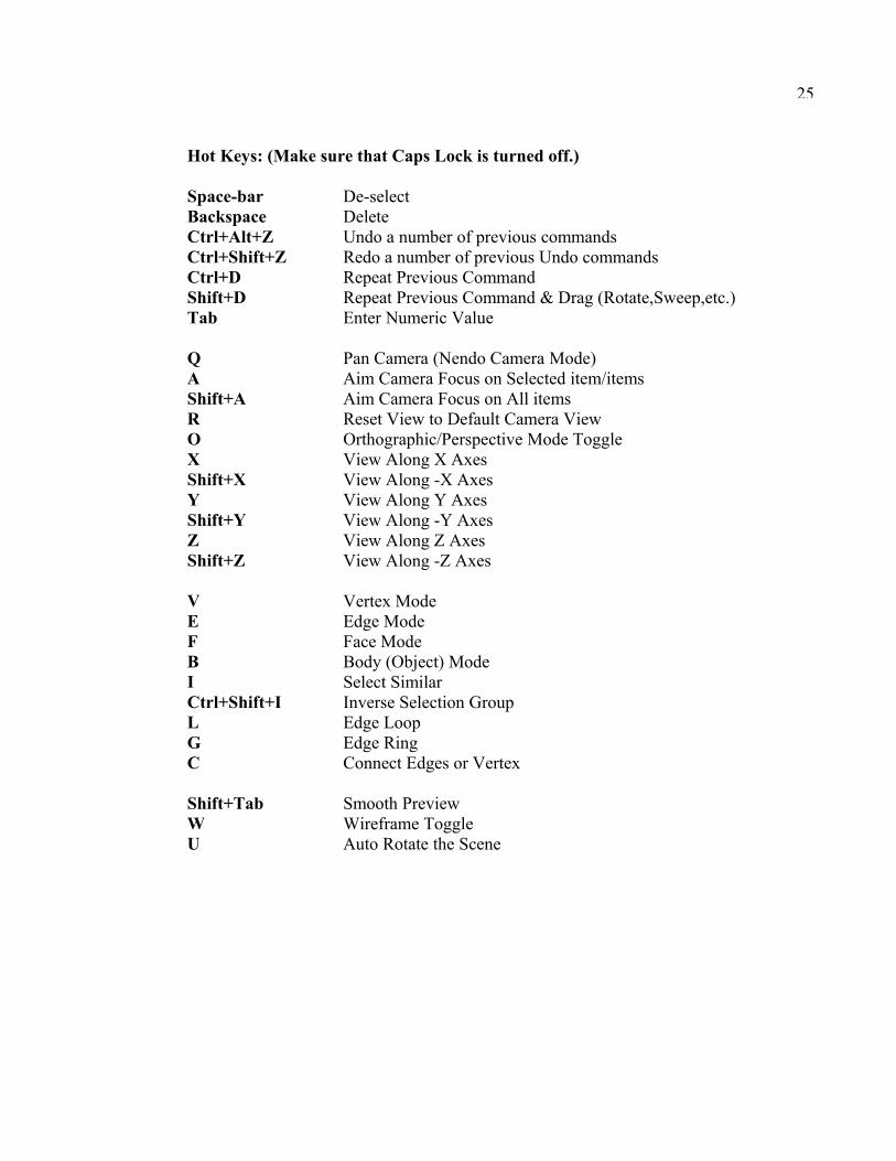
Hot Keys: (Make sure that Caps Lock is turned off.)
Space-bar De-select Backspace DeleteCtrl+Alt+Z Undo a number of previous commandsCtrl+Shift+Z Redo a number of previous Undo commandsCtrl+D Repeat Previous CommandShift+D Repeat Previous Command & Drag (Rotate,Sweep,etc.)Tab Enter Numeric Value
Q Pan Camera (Nendo Camera Mode)A Aim Camera Focus on Selected item/itemsShift+A Aim Camera Focus on All itemsR Reset View to Default Camera ViewO Orthographic/Perspective Mode ToggleX View Along X AxesShift+X View Along -X AxesY View Along Y AxesShift+Y View Along -Y AxesZ View Along Z AxesShift+Z View Along -Z Axes
V Vertex ModeE Edge ModeF Face ModeB Body (Object) ModeI Select SimilarCtrl+Shift+I Inverse Selection GroupL Edge LoopG Edge RingC Connect Edges or Vertex
Shift+Tab Smooth PreviewW Wireframe ToggleU Auto Rotate the Scene

26
Chapter 3
MaterialsBy default every Wings3D file contains two predefined Materials. If you look in the Outliner window you will see two box icons with an “M” with the Material descriptions “default” and “_hole_”.
The “default” material is the gray looking material applied to your model by default. The “_hole_” material can be applied to surfaces that you want to have ignored during various file exports. Surfaces with the “_hole_” material show up as transparent during Smooth Preview and in OpenGL Renders. These two materials cannot be deleted and it is best not to change their properties. The default color settings for these two materials can be changed in the user preferences [Edit > Preferences > General].
In order to control the surface properties of your model you will want to create new Materials [RMB > Material > Enter a new material name > OK]. On clicking OK the Material Properties Window will appear.
At the top of the window you will see controls for Diffuse, Ambient, Specular, Emission, Shininess, and Opacity. When Textures have been applied to your model, you will also see those Textures listed in the Material Properties Window. The types supported are Diffuse, Gloss, Bump (HeightMap), and NormalMap. Textures should be applied using the Snap Image tool so that UV Coordinates will be added with the texture. The Diffuse Texture can also be applied using the more advanced UV Mapping Command, which will be covered in the Chapter on UV Mapping.
This chapter will cover all these material properties. Material properties for external rendering software such as YafRay and Kerkythea will be covered in a separate chapter which will include information on Installation, Plug-in Configuration, Absorption, Dispersion, Refractive Caustics, Reflective Caustics, and More.
Color Swatches & Eyedropper Tool
Within the Material Properties Window you will see a color swatch next to various property controls. These will be either black or white by default. When you click [LMB] a color swatch a new window will open allowing you to change the color by adjusting the RGB (Red, Green, Blue) and/or HSV (Hue = Color, Saturation = Intensity, Value = Brightness) settings by either moving the sliders or entering numeric values. It is at this point that you can use the Eyedropper Tool. Moving the cursor away from the Choose Color Window will cause the eyedropper to automatically appear. Simply click a color anywhere within the Wings3D window set and the top portion of the color swatch will show that new color.
If you have an image which contains a special color you want to reproduce, you can use the Eyedropper Tool to grab the color from that image. In order to do this first load the image [File > Import Image...] and then view the image with the Wings3D image viewer [Outliner > LMB the Image > RMB > Show]. Now when you return to the Choose Color Window you can use the Eyedropper Tool to grab the color from the image in the viewer.
27
Diffuse
The Diffuse setting controls the true color of the Material as it would appear under Ambient white light. The Slider controls the V (Value = Brightness) setting within the HSV color model. Click the color swatch to the right of the Diffuse Slider Control to open the Choose Color Window.
Ambient
The Ambient setting affects the Diffuse color by simulating the presence of an Ambient light. The Slider controls the V (Value = Brightness) setting within the HSV color model. Click the color swatch to the right of the Ambient Slider Control to open the Choose Color Window.
Specular
The Specular setting controls the color that is reflected by the Material as a result of light shining on it. Gold Metal has a yellow/orange Specular Color. The Slider controls the V (Value = Brightness) setting within the HSV color model. Click the color swatch to the right of the Specular Slider Control to open the Choose Color Window.
Emission
The Emission setting controls the color that is emitted by the Material, a sort of glow. The Slider controls the V (Value = Brightness) setting within the HSV color model. Click the color swatch to the right of the Emission Slider Control to open the Choose Color Window.
Shininess
The Shininess setting controls how much light is reflected by the Material. Reducing the Shininess will increase the size of the Specular highlight.
Opacity
The Opacity setting controls how much light passes through the Material. Reducing the Opacity will increase the level of Transparency, with 0.0 being clear.
28
Textures & Snap Image Tool
When you are ready to apply a Texture/Image Map to your model you will want to use the Snap Image Tool [Tools > Snap Image]. This tool can be used to apply either a Diffuse, Gloss, Height Map, or Normal Map and will automatically add UV Coordinates.
Before you can use the Snap Image Tool you will need to load [File > Import Image...] your Texture/Image Map. If you try to use the Snap Image Tool without first loading an image you will get an error message stating that “No Images are Present”.
For best results apply textures while aligned to faces along each axes separately, whether X,Y, or Z. You should also make sure you are in Orthographic view as opposed to Perspective view. The Snap Image Tool is to be used while in Face Mode [F]. While in other modes, you will not have access to the most important “Snap Image” command.
The first thing you will be prompted for when you use the Snap Image Tool is the Image which you want to Snap to the selected faces. After you select your image, it will appear in the background of the Geometry Window.
When you click with the [RMB] you will see the Snap Image commands at the top of the context sensitive menu. Selecting the “Scale Snap Image” or the “Move Snap Image” command gives you access to commands for adjusting the Scale and Placement of the Texture.
When you are satisfied with the look and position of the texture, [RMB] and use the “Snap Image” command to snap the image to the selected faces. To exit the Snap Image Tool, [RMB] and select “Exit Snap Mode”.
29
Chapter 5
YafRay
You can render with YafRay using the built-in YafRay plug-in to produce Photo-realistic images. YafRay is capable of producing images with some fairly advanced effects. It is possible to produce effects like Absorption and Dispersion. You can get good Refractive (Glass) and Reflective (Metal) Caustics when you add a Photon Light (Spotlight) to your scene. You can even create scenes with Global Illumination when you add a Pathlight (Ambient) and Global Photonlight (Ambient).
Installation and Configuration
Although the YafRay plug-in is included as part of Wings3D, you will have to install the YafRay rendering program separately. YafRay is Open Source and can be freely downloaded from www.yafray.org. When you install YafRay, make sure you change the installation directory from the default to something like C:/YafRay, since using directory names with spaces (i.e. “Program Files”) can cause problems.
After you have installed YafRay, you must configure the YafRay Plugin [Edit > Plug-in Preferences > YafRay]. When the YafRay Options window is displayed, the only thing you have to change is the “Executable” field. You can either type in the path and file name for the YafRay Executable or Browse to the YafRay Executable and then close the window by clicking OK.
If you have not already done so, you will want to enable both “View image after rendering” and “Load image after rendering”, under the User Interface Tab of Preferences [Edit > Preferences], so that your rendered image will be displayed and listed in the Outliner Window when rendering is complete. This is also discussed in the User Preferences section of Chapter 1.
YafRay Materials
All the basic Material settings except for Ambient and Emission will have an affect on the rendered materials when you render with YafRay. In order for material Textures to show up when rendering with YafRay there must be additional Modulators present under the Material YafRay Options.