
The use of topology optimisation in the conceptual design of...
16
ABSTRACT Conventional commercial aircraft fuselages use all-aluminium semi-monocoque structures where the skin carries the external loads, the internal fuselage pressurisation and is strengthen using frames and stringers. Environmental and economic issues force aircraft designers to minimise weight and costs to keep air transport competitive and safe. But as metal designs have reached a high degree of perfection, extraordinary weight and cost savings are unlikely in the future. Carbon composite materials combined with lattice structures and the use of topology optimisation have the potential to offer such weight reductions. The EU FP7 project Advanced Lattice Structures for Composite Airframes (ALaSCA) was started to investigate this. This article present some of this research which has now led to the development of a new airframe concept which consists of: a load carrying inner skin; transverse frames; CFRP-metal hybrid stiffeners helically arranged in a grid configuration; insulating foam and an additional aerodynamic outer skin. AERONAUTICAL JOURNAL NOVEMBER 2013 VOLUME 117 NO 1197 1 Paper No. 3978. Manuscript received 22 March 2013, accepted 6 September 2013. The use of topology optimisation in the conceptual design of next generation lattice composite aircraft fuselage structures Steffen Niemann [email protected] Boris Kolesnikov [email protected] Heike Lohse-Busch [email protected] Christian Hühne [email protected] DLR, Braunschweig Germany Osvaldo M. Querin [email protected] Vassili V. Toropov [email protected] Dianzi Liu [email protected] University of Leeds Leeds, UK
-
Upload
nguyenxuyen -
Category
Documents
-
view
215 -
download
1
Transcript of The use of topology optimisation in the conceptual design of...

ABSTRACTConventional commercial aircraft fuselages use all-aluminium semi-monocoque structures where the skin carries the external loads, the internal fuselage pressurisation and is strengthen using frames and stringers. Environmental and economic issues force aircraft designers to minimise weight and costs to keep air transport competitive and safe. But as metal designs have reached a high degree of perfection, extraordinary weight and cost savings are unlikely in the future. Carbon composite materials combined with lattice structures and the use of topology optimisation have the potential to offer such weight reductions. The EU FP7 project Advanced Lattice Structures for Composite Airframes (ALaSCA) was started to investigate this. This article present some of this research which has now led to the development of a new airframe concept which consists of: a load carrying inner skin; transverse frames; CFRP-metal hybrid stiffeners helically arranged in a grid configuration; insulating foam and an additional aerodynamic outer skin.
AeronAuticAl JournAl november 2013 volume 117 no 1197 1
Paper No. 3978. Manuscript received 22 March 2013, accepted 6 September 2013.
The use of topology optimisation in the conceptual design of next generation lattice composite aircraft fuselage structuresSteffen Niemann [email protected] Kolesnikov [email protected] Lohse-Busch [email protected] Hühne [email protected], Braunschweig Germany
Osvaldo M. Querin [email protected] V. Toropov [email protected] Liu [email protected] of Leeds Leeds, UK

2 the AeronAuticAl JournAl november 2013
NOMENCLATUREALaSCA Advanced Lattice Structures for Composite AirframesAR aspect ratioCFRP carbon-fibre-reinforced-plasticscLoad compliance value for specific load caseCTot total structural complianceEI bending stiffnessGJ shear stiffnessLamAiR Laminar Aircraft Researchn number of the analysed finite elementN total number of finite elements in the designable part of the structureR fuselage radiusVn volume of the analysed finite elementV0 maximum volume of the designable structureγmax maximum shear strainεcmax maximum compressive strainεtmax maximum tensile strainθgs angle between the grid stiffenersρ design variable and artificial element density used by the SIMP method, or material
densityωload weighting factor for specific load case
1.0 INTRODUCTIONConventional commercial aircraft fuselages use all-aluminium semi-monocoque structures, which exploit the isotropic properties of the metal. The skin carries the external loads from the wings, empennage, engines, etc. as well as the internal pressurisation of the fuselage. The skin is then strengthened using a series of frames and stringers which are either riveted or bonded(1). These components are used to make large tubular sections, which are then joined with fasteners to form the complete fuselage.
Environmental and economic issues force future aircraft designs to maximise efficiencies in weight and cost to keep air transport competitive and safe. But as metal designs have reached a high degree of perfection, extraordinary weight and cost savings are unlikely to be achieved in the future(2).
Carbon composites have high values of specific strength and rigidity, but the way in which they are currently used only provide a weight benefit of 10–20 %(3). Carbon fibre reinforced plastics (CFRP) have a specific strength 5 to 6 times higher and a specific rigidity 2-3 times higher than aluminium alloys(4). The potential of composites has therefore not been completely realised using conventional aircraft airframe layouts(5).
In the 1980s, the composite lattice structure was developed by the Russian Central Research Institute for Special Machinery (CRISM) for rocket structures(6), Fig. 1(7). These structures consist of ribs either helically or ring shaped made of unidirectional composites fibres using automatic filament winding. The skin of the cylindrical or conical shells is usually manufactured from carbon fabric and only carries an insignificant part of the loading (tension, compression and shear). The high mechanical properties of the unidirectional composites of the lattice ribs are the main factor for their high weight efficiency. The automatic filament winding process ensures an

Querin et al the use of topology optimisAtion in the conceptuAl design of A next generAtion... 3
integral structure with a low manufacturing cost. These structures are most efficient if they are undisturbed, (i.e. without cut-outs etc.) and at present are therefore predominantly applied in sections of space rockets(3).
These experiences open up new opportunities for the optimisation of composite aircraft fuselage barrels(2). To determine this potential, a demonstrator was built as the DLR black fuselage concept(8,9). However, the barrel section was never implemented in a flying aircraft.
In order to address some of the issues associated with the implementation of composite lattice structure into commercial aircraft, the EU FP7 project titled Advanced Lattice Structures for Composite Airframes (ALaSCA) was started. This project consisted of carrying out a compre-hensive investigation into the benefits of using the geodesic composite lattice structures used in the rocket industry and transferring the technology to the design of composite aircraft fuselages(10).
The aim of this article is to present some of the work carried out within the ALaSCA project, which demonstrates that topology optimisation can be an integral tool in the design of composite lattice aircraft fuselage barrel sections. The article presents: (1) the topology optimisation problem, results and their interpretation; (2) the different aspects of the primary composite lattice aircraft fuselage structure design, and (3) results and conclusions of this study.
Figure 1. A typical composite lattice structure without the external skin.
Figure 1 A typical composite lattice structure without the external skin
Figure 2 The LamAiR aircraft configuration +
Figure 3 Side view of the fuselage showing the different bays
Figure 2 The LamAiR aircraft configuration.

4 the AeronAuticAl JournAl november 2013
1.1 Aircraft configuration and loads
This study used the aircraft configuration of the DLR funded project LamAiR, Fig. 2. The aim of that project was to increase the technology readiness level of the laminar airflow technology for short and medium range aircraft configurations(11).
The LamAiR aircraft configuration consists of a long fuselage barrel section mounted ahead of a forward swept wing and rear mounted turbine engines. Since the passenger and cargo doors (large cut-outs) are in the front cockpit-section or behind the wing, a long undisturbed barrel section can be designed as the main fuselage section. A composite lattice structure, together with the use of topology optimisation are ideally suited for this type of configuration as it can lead to a light weight and cost efficient fuselage design. This configuration was therefore used in this study.
The loads for the fuselage barrel were analysed with the Preliminary Aircraft Design and Optimisation (PrADO) program(12). Four critical flight load cases were investigated and used to dimension the barrel. These load cases were: (1) two gust load cases (vertical and lateral) at low altitude; (2) one gust load case (vertical and lateral) at its maximum altitude and (3) a static internal pressure test load case whilst on the ground. Due to the rear position of the wing, this type of fuselage configuration experiences higher loads than an equivalent conventional swept back wing configuration.
1.2 Requirements and sizing criteria
This study considered structural stability (local and global), strength and stiffness requirements. The local stability considered the stiffener column buckling, stiffener crippling and skin bay buckling; and the global stability considered the global fuselage structural stability and the panel buckling between the frames.
The strength requirements were considered as global strain limits which could not be exceeded anywhere within the structure. These strain cut-offs were different for tension, compression and shear and their values were: εcmax = 3,000μs, εtmax = 4,500μs and γmax = 5,000μs. To guarantee comptibility of the barrel sections at the interfaces with the cockpit and wing sections and to satisfy the aero-elastic requirements, the following minimum bending (EI) and shear (GJ) stiffness values were specified: ExIymin
= 4·0 × 1015 Nmm2, ExIzmin = 3·0 × 1015 Nmm2, and GxyJmin = 2·5 × 1015
Nmm2 Additional requirements such as damage tolerance and repair were only considered qualitatively.
2.0 TOPOLOGY OPTIMISATIONIn aluminium structures, the fuselage stiffeners are commonly arranged in the same direction as the axis of the fuselage and are evenly distributed along its circumference. The use of composite materials(7) allows for these stiffeners to be arranged along any axis. The Solid Isotropic Material with Penalisation (SIMP)(13) topology optimisation method was used to determine their optimal orientation. This was achieved using Altair’s OptiStruct program(14) which has its own finite element analysis solver.
The optimisation problem consisted of minimising the compliance of the fuselage section subject to the applied loads. This optimisation problem is given by (1). Note that the buckling requirements were not considered at this stage.
. . . (1)
min
subject to
C
V V
n N
Tot
n nn
N
01
11
,...,
min
Querin et al the use of topology optimisAtion in the conceptuAl design of A next generAtion... 5
where: CTot is the total compliance for the structure, calculated using (2) described in section 2·3; N is the total number of finite elements in the designable part of the structure; n is the number of the analysed finite element; ρ is the design variable and artificial element density used by the SIMP method to optimise each finite element in the structure. Since the fuselage skin thickness could vary from 30mm (full stiffener present) down to 0·1mm (only outer skin membrane present), the value of ρmin used was 0·00333. Vn is the volume of the analysed finite element and V0 is the maximum volume of the designable structure.
2.1 Fuselage section
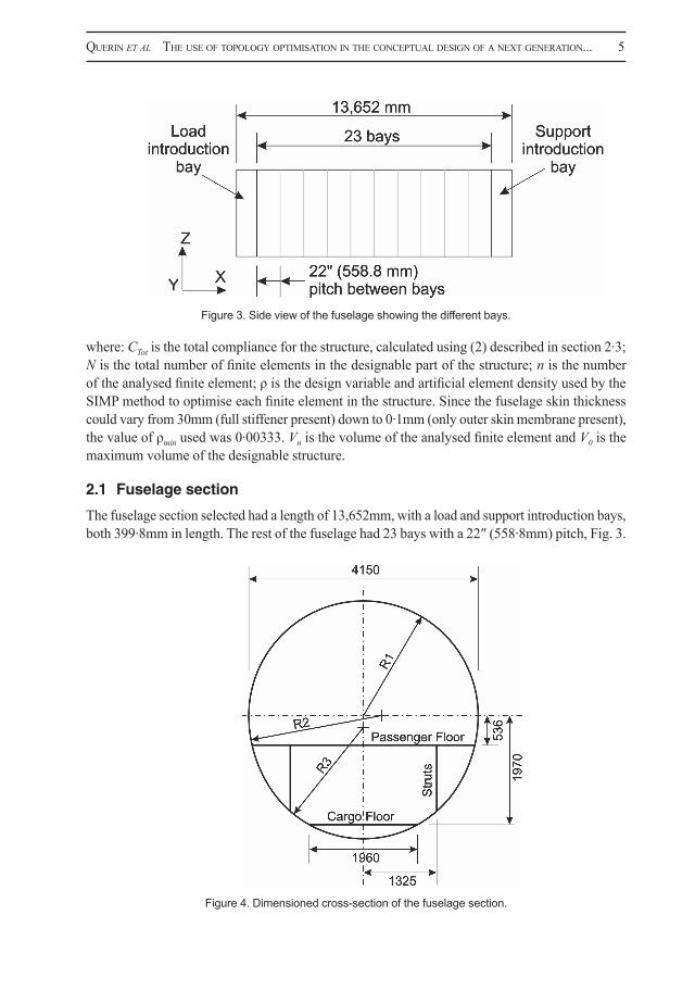
The fuselage section selected had a length of 13,652mm, with a load and support introduction bays, both 399·8mm in length. The rest of the fuselage had 23 bays with a 22″ (558·8mm) pitch, Fig. 3.
Figure 1 A typical composite lattice structure without the external skin
Figure 2 The LamAiR aircraft configuration +
Figure 3 Side view of the fuselage showing the different bays
Figure 3. Side view of the fuselage showing the different bays.
Figure 4 Dimensioned cross-section of the fuselage section
Figure 5 Fuselage section showing the loads applied at the free end
Figure 4. Dimensioned cross-section of the fuselage section.

6 the AeronAuticAl JournAl november 2013
Figure 4 Dimensioned cross-section of the fuselage section
Figure 5 Fuselage section showing the loads applied at the free end
Figure 5. Fuselage section showing the loads applied at the free end.
Figure 6 Fuselage cross-section showing the passenger and cargo floor loads
2.3 Optimization Parameters
The fuselage was optimised for each load case individually. The compliance values of the optimal
topologies for the individual load cases were then used to determine the multi-load weighting factors.
These were used to calculate the multi-load case compliance value of (2), which was used to optimise
all load cases applied simultaneously. The logic behind this was that if the compliance value for the
optimal topology of one of the load cases was higher than the others, that particular load case was
critical. Hence it should have a higher weighting in the total weighted compliance. The weighting
factors for the fuselage without windows were: 1 =0.4483, 2 =0.1604,3 =0.3913, and with
windows were: 1 =0.700, 2 = 0.252,3 = 0.048.
332211
3
1ccccC
LoadLoadLoadTot
(2)
2.4 Optimal Layout of Stiffeners
The fuselage section was optimised: 1) without windows, and 2) with windows. The results are given
in Figure 7 and Figure 8 respectively.
Figure 6. Fuselage cross-section showing the passenger and cargo floor loads.

Querin et al the use of topology optimisAtion in the conceptuAl design of A next generAtion... 7
The cross section was made from three different radii and included a passenger and a cargo floor with struts connecting the two, Fig. 4. For the sising process of Section 4, a more simplified circular fuselage cross-section with a 2·0m radius was used.
Two different fuselage models were optimised, one with windows and one without. The model without windows used 25,584 shell elements, 5,842 beam elements and one RBE2 element(14), making it a total of 31,427 FE, Fig. 7. The model which included windows used 25,100 shell elements, 5,842 beam elements and one RBE2 element, making it a total of 30,943 FE, Fig. 8.
2.2 Applied loads
The loads applied consisted of: a) distributed masses on the fuselage and its frames; b) point loads on the passenger and cargo floors; and c) point loads and moments at the free end of the fuselage barrel section.
There were five loads applied at the free end as three separate load cases, with the notation of Fig. 5. Load case 1 consisted of a vertical shear force Qz = 211,711N and moment My = 446,965Nm. Load case 2 consisted of a torque about the x axis applied in both directions, T = ±280kNm. Load case 3 consisted of a horisontal shear force Qy = ±80kN and a bending moment Mz = 249,614Nm applied in both directions. As part of Load case 1, a 3·47 load factor was applied acting in the negative z direction on the mass of the fuselage and rings present at the bay locations. The fuselage mass of 2,461·9kg was evenly distributed over the entire fuselage and the ring frames mass of 1,322·8kg was evenly distributed over the 23 rings. The passenger and cargo floor loads shown in Fig. 6 had the magnitudes: FPassenger = 3,238·5N, FCC = 1,510N and FCL = 755N.
2.3 Optimisation parameters
The fuselage was optimised for each load case individually. The compliance values of the optimal topologies for the individual load cases were then used to determine the multi-load weighting factors. These were used to calculate the multi-load case compliance value of Ref. 2, which was used to optimise all load cases applied simultaneously. The logic behind this was that if the compliance value for the optimal topology of one of the load cases was higher than the others, that particular load case was critical. Hence it should have a higher weighting in the total weighted compliance. The weighting factors for the fuselage without windows were: ω1 = 0·4483, ω2 = 0·1604, ω3 = 0·3913, and with windows were: ω1 = 0·700, ω2 = 0·252, ω3 = 0·048.
. . . (2)
2.4 Optimal layout of stiffeners
The fuselage section was optimised: 1) without windows, and 2) with windows. The results are given in Fig. 7 and Fig. 8 respectively.
2.5 Comments on the topology results
The results of Figs 7 and 8 show two very distinctive features which have emerged as a consequence of the topology optimisation process: 1) Substantially sized backbones on the upper and lower extremities of the fuselage cross-section, and 2) Smaller rib-like stiffeners which start and end on the backbones, and which criss-cross each other at different angles ranging from approximately 45° for fuselages with windows and approximately 60° for fuselages without windows. The ideal stiffener arrangement would therefore have continually varying angles. These would start parallel to the fuselage axis and vary to have a maximum angle where these pass the window locations, Fig. 9.
C c c c cTot Load LoadLoad
1
3
1 1 2 2 3 3

8 the AeronAuticAl JournAl november 2013
Figure 7 Optimal stiffener layout for the fuselage without windows
Figure 8 Optimal stiffener layout for the fuselage with windows
Figure 7 Optimal stiffener layout for the fuselage without windows
Figure 8 Optimal stiffener layout for the fuselage with windows
Figure 7. Optimal stiffener layout for the fuselage without windows.
Figure 8. Optimal stiffener layout for the fuselage with windows.

Querin et al the use of topology optimisAtion in the conceptuAl design of A next generAtion... 9
Figure 9 Fuselage barrel showing the continually varying angle stiffener arrangement
Figure 10 Fuselage section showing the angled stiffeners with different stiffener density above and below the window region
Figure 9. Fuselage barrel showing the continually varying angle stiffener arrangement.
3.0 INTERPRETATION OF TOPOLOGY OPTIMISATION RESULTS
The topology results suggest a strong stiffening backbone with ribs which run from these backbones in a stiffener arrangement with variable angles, Fig. 9. However, these stiffeners are very complex and expensive to manufacture due to their continual varying sizes. Whereas stiffeners with constant cross-section and curvature are much easier and less expensive to produce if continuous production process, like pultrusion(15) are used.
For this reason, the design suggested by topology optimisation was simplified by using stiffeners of constant angle. These stiffeners were then aligned along geodesic lines on the fuselage skin, Fig. 10· An added benefit of this arrangement is that it prevents secondary bending of the stiffeners.
4.0 DESIGN OF THE PRIMARY AIRCRAFT FUSELAGE STRUCTURE
To size the skin and stiffeners for the design of Fig. 10, an analytical investigation was carried out using standard beam theory, composite laminate theory and linear buckling. This investigation used different thicknesses for each component in order to find the most suitable one. The material used for the skin was Hexcel 8552/AS4(16), which is a CFRP material with the following individual ply properties: Young’s modulus E0° = 141GPa, E90° = 10GPa, density ρ = 1,550kg/m³.

10 the AeronAuticAl JournAl november 2013
4.1 Grid aspects
The use of the lattice structure of Fig. 10 generates non-rectangular skin bays segments in a grid-like arrangement which considerably improves the buckling resistance of these skin bays(17), Fig. 11(b). It is therefore possible to either decrease the skin thickness or increase the stiffener’s distance in comparison to the rectangular skin bays. An advantage of the grid arrangement is that the number of stiffeners is doubled for the same overall mass, Fig. 11.
A negative consequence of these grid stiffeners with very thin laminate thicknesses is that they exhibit reduced axial stiffness when compared to conventional stiffened panels. This is primarily due to the aircraft industry requirements for repair and joining damage tolerance. In order to address this problem, a newly developed CFRP-metal-hybrid-material was used(18,19). This material has a high longitudinal stiffness because each CFRP unidirectional ply is bonded with a thin steel foil. The CFRP-metal hybrid is then stacked to produce the required laminate thickness. A penalty of using the CFRP-metal hybrid material is that it has a significantly higher density of 1,990kg/m³, an increase of 28% compared to conventional CFRP.
4.2 Analysis of grid arrangements
The design concept consists of a load bearing skin, stiffeners in grid arrangement made from a CFRP-metal-hybrid-material and frames as circumferential stiffeners. The use of typical C-shaped frames was fixed in advance in order to properly apply the cabin loads into the primary structure. The aim of this part of the study was to increase the buckling resistance of the proposed new structure of Fig. 10.
Figure 10. Fuselage section showing the angled stiffeners with different stiffener density above and below the window region.
Figure 9 Fuselage barrel showing the continually varying angle stiffener arrangement
Figure 10 Fuselage section showing the angled stiffeners with different stiffener density above and below the window region

Querin et al the use of topology optimisAtion in the conceptuAl design of A next generAtion... 11
A comparison of rectangular and triangular skin bays was carried out in order to obtain the buckling factor for the triangular skin bay. The study was done using the software packages MSC Nastran and MSC Patran(20). The finite element model was made using the Nastran-Quad4 shell element using isotropic material properties (rather than orthotropic) in order for this study to focus on the geometric effects of these panels.
Three models were analysed, Fig. 12(a): (1) a rectangular skin bay with simply supported edges; (2) a single triangular skin bay with simple supported edges; and (3) a rectangular panel with a triangular grid structure with simple support edges and symmetrical boundary conditions. Two finite element meshes were investigated: (1) Medium, with an element size equivalent to 1/20th the width of each configuration; and (2) Fine, with an element size equivalent to 1/40th the width of each configuration. Since both meshes produced the same results, the Medium mesh was used for all subsequent analysis. A skin thickness of 3/1,000th of the width of each configuration was used to comply with thin plate theory.
All three configurations were modelled with increasing aspect ratio (AR) (length/width) from 0·5 to 30 and loaded with a pure compressive and shear loads (configuration 2 used compression only) recording the buckling factors. The angle between the grid stiffeners (θgs) was directly calculated from the aspect ratio of each panel using (3). Hence the range of angles analysed varied from θgs = 90°(AR = 0·5) to θgs = 1·91° (AR = 30).
. . . (3)
The buckling factors were normalised to the lowest buckling factor, which was model (1) and are shown in Fig. 12(b). The buckling result of the analysis on the barrel configuration of Fig. 10 is also shown in the same figure for comparison.Two factors were observed in the triangular bays which contribute to their increased buckling resistance:1. The effective width of the buckled region decreased as the AR was increased.2. The fixed support at the apex of the triangle provided extra stiffening.
This resulted in a 30% increase in the buckling factor when compared with a rectangular bay of equivalent AR.
(a)
(b)
Figure 11 Comparison of: (a) the conventional stringer stiffened panel and (b) the grid arrangement
(a)
(b)
(c)
Figure 12 (a) The three buckling models, (b) the calculated buckling coefficients and (c) the buckling mode shapes for the three models obtained from the finite element analysis
Figure 11. Comparison of: (a) the conventional stringer stiffened panel and (b) the grid arrangement.
gs AR
2 12
1Tan

12 the AeronAuticAl JournAl november 2013
4.3 Comparison of the semi-monocoque concepts
Four semi-monocoque concepts were analytically analysed using the barrel section dimensions of Figs 3 and the concept of Fig. 10: (1) A conventional semi-monocoque with CFRP stiffeners and 1·625mm skin thickness; (2) A conventional semi-monocoque with CFRP-metal hybrid stiffeners and 1·625mm skin thickness; (3) A grid arrangement with CFRP stiffeners and 1·625mm skin thickness; and (4) A grid arrangement with CFRP-metal hybrid stiffeners and 2·75mm skin thickness. The stringer and frame arrangement was the same for all four concepts, with only one design variable, the stringer cross-sectional area. The frame pitch used was 500mm. The stringer pitch above the window line was 150mm, giving a total of 24 stringers. The stringer pitch below the window line was 105mm, giving a total of 81 stringers, Fig. 10.
The only structural components used in the weight comparison were the fuselage skin, stiffeners and frames, Fig. 13. The results for each configuration were normalised with respect to the base concept 1. The use of CFRP-metal hybrid stiffeners in concept 2 gave a 14·4% weight reduction. The use of a grid arrangement gave a 17·7% weight reduction, and the combination of grid and CFRP-metal hybrid stiffeners gave the best weight reduction, totalling 20%.
4.4 Grid concept
The grid arrangement concepts provide the best weight savings, however they are also the most challenging to manufacture. If the stiffeners are placed on one side of the skin, at the location where the stiffeners cross, one of them has to be cut to let the other one through. This reduces the structural integrity of the cut stiffeners and requires a significant weight penalty to remedy. For this reason, a new design was developed as part of this work. The stiffeners in one helical direction are placed on the inside of the skin, and those in the opposite direction are placed on the outside of the skin, Fig. 14. A consequence of this is that the stiffeners on the outside have to
(a)
(b)
Figure 11 Comparison of: (a) the conventional stringer stiffened panel and (b) the grid arrangement
(a)
(b)
(c)
Figure 12 (a) The three buckling models, (b) the calculated buckling coefficients and (c) the buckling mode shapes for the three models obtained from the finite element analysis
(a) (b)
(c)
Figure 12. (a) The three buckling models, (b) the calculated buckling coefficients and (c) the buckling mode shapes for the three models obtained from the finite element analysis.

Querin et al the use of topology optimisAtion in the conceptuAl design of A next generAtion... 13
be covered by an aerodynamic skin and require additional material to be added in order to fill the space between the internal pressurised skin and the aerodynamic outside skin, Fig. 14. These two extra components had to then be added to the weight estimation calculation.
The aerodynamic skin consisted of 0·2mm thick aluminium, which also serves as the lightning strike protection layer. The filling material selected was the closed-cell foam Rohacell 31 IG with a Young’s modulus of 36MPa and density of 31kg/m³(21). This material is very light, provides good thermal insulation and is applicable for primary structures. The combination of an outer skin and internal foam also provide increased impact resistance of the primary structural components. In order to determine which concept provided the best weight savings, the additional weights of these new components (skin, foam, lightning strike material) were added to those of the primary structure from Fig. 13 and are given in Fig. 15. As was done for Fig. 13, the results for each configuration
Figure 13 Structural weight comparison for the four investigated concepts
Figure 14 Airframe grid concept showing the primary structure elements
30.0 33.5 30.0
50.9
62.444.5
44.6
21.5
7.6
7.67.6 7.6
0
10
20
30
40
50
60
70
80
90
100
Concept 1 Concept 2 Concept 3 Concept 4
% W
eigh
t per
uni
t len
gth
Skin Stiffeners Frames
Bearing Skin Stiffener grid
Frame
Aerodynamic skin
Foam core
Bearing Skin Stiffener grid
Frame
Aerodynamic skin
Foam core Figure 13 Structural weight comparison for the four investigated concepts
Figure 14 Airframe grid concept showing the primary structure elements
30.0 33.5 30.0
50.9
62.444.5
44.6
21.5
7.6
7.67.6 7.6
0
10
20
30
40
50
60
70
80
90
100
Concept 1 Concept 2 Concept 3 Concept 4
% W
eigh
t per
uni
t len
gth
Skin Stiffeners Frames
Bearing Skin Stiffener grid
Frame
Aerodynamic skin
Foam core
Bearing Skin Stiffener grid
Frame
Aerodynamic skin
Foam core
Figure 13. Structural weight comparison for the four investigated concepts.
Figure 14. Airframe grid concept showing the primary structure elements.

14 the AeronAuticAl JournAl november 2013
Figure 15 Comparison of the structural weight of all the concepts including the thermal insulation
foam and aerodynamic skin with lightning strike protection material
Figure 16 Final ALaSCA fuselage barrel concept incorporating a grid structure and using an inner skin between the CFRP-metal hybrid stiffeners
27.1 30.0 27.1
45.7
55.740.0 40.0
19.3
6.4
6.4 6.4 6.4
6.4
6.4 8.6 8.6
4.3
4.3 5.7 5.7
0
10
20
30
40
50
60
70
80
90
100
Concept 1 Concept 2 Concept 3 Concept 4
% W
eigh
t per
uni
t len
gth
Skin Stiffeners Frames Foam Aerodynamic skin
Figure 15. Comparison of the structural weight of all the concepts including the thermal insulation foam and aerodynamic skin with lightning strike protection material.
Figure 16. Final ALaSCA fuselage barrel concept incorporating a grid structure and using an inner skin between the CFRP-metal hybrid stiffeners.
Figure 15 Comparison of the structural weight of all the concepts including the thermal insulation
foam and aerodynamic skin with lightning strike protection material
Figure 16 Final ALaSCA fuselage barrel concept incorporating a grid structure and using an inner skin between the CFRP-metal hybrid stiffeners
27.1 30.0 27.1
45.7
55.740.0 40.0
19.3
6.4
6.4 6.4 6.4
6.4
6.4 8.6 8.6
4.3
4.3 5.7 5.7
0
10
20
30
40
50
60
70
80
90
100
Concept 1 Concept 2 Concept 3 Concept 4
% W
eigh
t per
uni
t len
gth
Skin Stiffeners Frames Foam Aerodynamic skin

Querin et al the use of topology optimisAtion in the conceptuAl design of A next generAtion... 15
were normalised with those of the base concept 1. The lightning strike protection for concepts 1 and 2 was provided by a copper mesh with an area density of 370g/m², and the thermal insulation was provided by a mineral wool layer with an area density of 600g/m². For concepts 3 and 4, the lightning strike protection was provided by a thin aluminium layer with an area density of 540g/m² and the thermal insulation was provided by the Rohacell 31 IG closed-cell foam with an area density of 775g/m².
The inclusion of insulating material and of the lightning strike protection material to the aerody-namic skin resulted in a slight change in the weights of the four concepts. The use of CFRP-metal hybrid stiffeners in concept 2 with the copper mesh gave a 12·9% weight reduction. The grid arrangement of concept 3 with the aluminium light protection layer gave a 12·1% weight reduction so is now heavier than concept 2. But concept 4 with the combination of grid and CFRP-metal hybrid stiffeners and aluminium light protection still gave the best overall weight reduction of 14·3%.
4.5 Final fuselage barrel concept
By implementing all of these findings, the design of Fig. 10 was re-evaluated and the new design concept for the ALaSCA fuselage barrel is now given in Fig. 16. There is a decrease in the number of stiffener over the length of the barrel due to a decrease in the fuselage loading. This is comparable with the topology optimisation results of Figs 7 and 8.
5.0 CONCLUSIONTopology optimisation was applied to the fuselage barrel subjected to three load cases. The topologies which emerged revealed the need for stiffeners to be concentrated on the upper and lower extremities of the fuselage cross section and for these to form a criss-cross mesh pattern along the sides of the fuselage.
This research has led to the development of a new airframe concept. It consists of a load carrying inner skin with transverse frames and CFRP-metal hybrid stiffeners arranged helically in a grid configuration. The stiffeners are oriented in opposite directions on either side of the inner skin. This was then covered with thermally insulating foam and an outer aerodynamic skin made from aluminium. An aspect yet to be resolved of this design is the ability to carry out inspections during service.
ACKNOWLEDGEMENTSThe authors acknowledge the support of the European Commission and the Russian government within the currently run FP7 Advanced Lattice Structures for Composite Airframes (ALaSCA) research project.
REFERENCES1. bruhn, E.F. Analysis and Design of Flight Vehicle Structures, Jacobs Publishing Inc, 1973.2. shAnygin, A., fomin, v. and KondAKov, i. Designing Pro-Composite Aircraft Concepts and Layouts to
Maximise Potential Benefits of High Specific Strength of CFRP, 28th Congress of the International Council of the Aeronautical Sciences, 23–28 September 2012, Brisbane, Australia, Paper: ICAS 2012-1.7.3.
3. vAsiliev, V.V. and rAzin, A.F. Anisogrid composite lattice structures for spacecraft and aircraft applications, Composite Structures, October 2006, 76, (1–2), pp 182–189.
4. dAniel, I.M. and ishAi, O. Engineering Mechanics of Composite Materials, Oxford University Press, 2nd ed, 2005.

16 the AeronAuticAl JournAl november 2013
5. ostrower, J. flightglobal.com, 15 March 2011. (Online). http://www.flightglobal.com/news/articles/boeing-to-miss-787-performance-spec-albaugh-354340/.
6. vAsiliev, V.V., bArynin, V.A. and rAzin, A.F. Anisogrid lattice structures – survey of development and application, Composite Structures, November–December 2001, 54, (2–3), pp 361-370.
7. vAsiliev, V.V., bArynin, V.A. and rAzin, A.F. Anisogrid composite lattice structures – Development and aerospace applications, Composite Structures, February 2012, 94, (3), pp 1117–1127.
8. herbecK, l., wilmes, h.r., KolesniKov, b. and Kleineberg, m. Technology and design development for a CFRP fuselage. In 25th SAMPE Europe Conference, Paris, France, 2003.
9. wilmes, h., KolesniKov, b., finK, A. and KindervAter, C. New design concepts for a CFRP fuselage. In Workshop at German Aerospace Centre (DLR) on Final Project of Black Fuselage, Braunschweig, Germany, 2002.
10. EU Research Project, Advanced Lattice Structures for Composite Airframes (ALasCA), Project Reference: 265881, 2010 – 2013, Available: http://eu-project.vc/cordis-news/eu-research-projects-37.html (Accessed 18/07/2013).
11. seitz, A., Kruse, m., wunderlich, t., bold, J. and heinrich, l. The DLR Project LamAiR: Design of a NLF Forward Swept Wing for Short and Medium Range Transport Application, 29th AIAA Applied Aerodynamics Conference, June 2011, AIAA 2011-3526.
12. gerhold, T. Overview of the hybrid RANS TAU-Code, Notes on Multidisciplinary Design, 2005, 89, pp 81-92.
13. bendsøe, M. and sigmund, O. Topology Optimization: Theory, Methods and Applications, Springer, 2003.14. Altair OptiStruct19, (Online). Available: http://www.altairhyperworks.com/Product, 19,OptiStruct.aspx.
(Accessed 18/07/2013).15. meyer, R.W. Handbook of Pultrusion Technology, Chapman and Hall, 1985.16. Hexcel. (Online). Available: http://www.hexcel.com/Resources/DataSheets/Prepreg-Data-Sheets/8552_
eu.pdf (Accessed 23/07/2013).17. tAn, h.K.v., bettess p. and bettess J.A. Elastic buckling of isotropic triangular flat plates by finite
elements, Applied Mathematical Modelling, October 1983, 7, (5), pp 311-316.18. stefAniAK, d., KolesniKov, b. and KAppel, e. Improving impact endangered CFRP structures by
metal-hybridisation, Proceedings of 12th European Conference on Spacecraft Structures, Materials and Environmental Testing, European Space Agency, (Special Publication) ESA SP, v 691 SP, 2012.
19. wiedemAnn, m., sinApius, m. and melcher, J. Innovation Report, Institute of Composite Structures and Adaptive Systems, DLR, Germany, 2012.
20. MSC Software. Simulating Reality, Delivering Certainty, (Online. Available: http://www.mscsoftware.com/ (Accessed 19/07/2013).
21. RohaSell-on-Line. (Online. Available: http://www.rohasell-on-line.com/products.html (Accessed 23/07/2013).


