Fibre Optic Distributed Temperature Sensing Systemopticalsensing-hk.com/pdf/catalog3.pdf · The...
8
Advanced. Dependable. Functional. Fibre Optic Distributed Temperature Sensing System
Transcript of Fibre Optic Distributed Temperature Sensing Systemopticalsensing-hk.com/pdf/catalog3.pdf · The...
Advanced. Dependable. Functional.
Fibre Optic Distributed Temperature Sensing System
Advanced. Dependable. Functional.
Introduction of FODTS
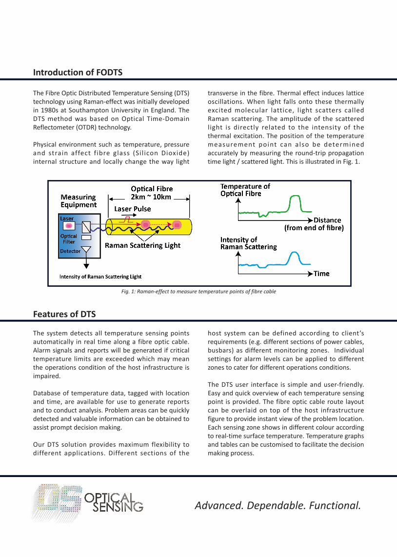
The Fibre Optic Distributed Temperature Sensing (DTS) technology using Raman-effect was initially developed in 1980s at Southampton University in England. The DTS method was based on Optical Time-Domain Reflectometer (OTDR) technology.
Physical environment such as temperature, pressure and strain affect f ibre glass (Si l icon Dioxide) internal structure and locally change the way light
transverse in the fibre. Thermal effect induces lattice oscillations. When light falls onto these thermally excited molecular lattice, l ight scatters called Raman scattering. The amplitude of the scattered light is directly related to the intensity of the thermal excitation. The position of the temperature measurement point can also be determined accurately by measuring the round-trip propagation time light / scattered light. This is illustrated in Fig. 1.
Features of DTS
The system detects all temperature sensing points automatically in real time along a fibre optic cable. Alarm signals and reports will be generated if critical temperature limits are exceeded which may mean the operations condition of the host infrastructure is impaired.
Database of temperature data, tagged with location and time, are available for use to generate reports and to conduct analysis. Problem areas can be quickly detected and valuable information can be obtained to assist prompt decision making.
Our DTS solution provides maximum flexibility to different applications. Different sections of the
host system can be defined according to client’s requirements (e.g. different sections of power cables, busbars) as different monitoring zones. Individual settings for alarm levels can be applied to different zones to cater for different operations conditions.
The DTS user interface is simple and user-friendly. Easy and quick overview of each temperature sensing point is provided. The fibre optic cable route layout can be overlaid on top of the host infrastructure figure to provide instant view of the problem location. Each sensing zone shows in different colour according to real-time surface temperature. Temperature graphs and tables can be customised to facilitate the decision making process.
Fig. 1: Raman-effect to measure temperature points of fibre cable
Advanced. Dependable. Functional.
The Science Behind FODTS
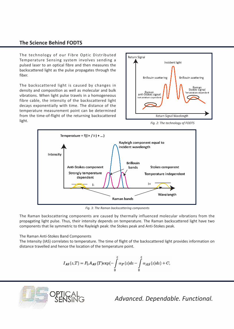
The technology of our F ibre Optic Distr ibuted Temperature Sensing system involves sending a pulsed laser to an optical fibre and then measures the backscattered light as the pulse propagates through the fiber.
The backscattered light is caused by changes in density and composition as well as molecular and bulk vibrations. When light pulse travels in a homogeneous fibre cable, the intensity of the backscattered light decays exponentially with time. The distance of the temperature measurement point can be determined from the time-of-flight of the returning backscattered light.
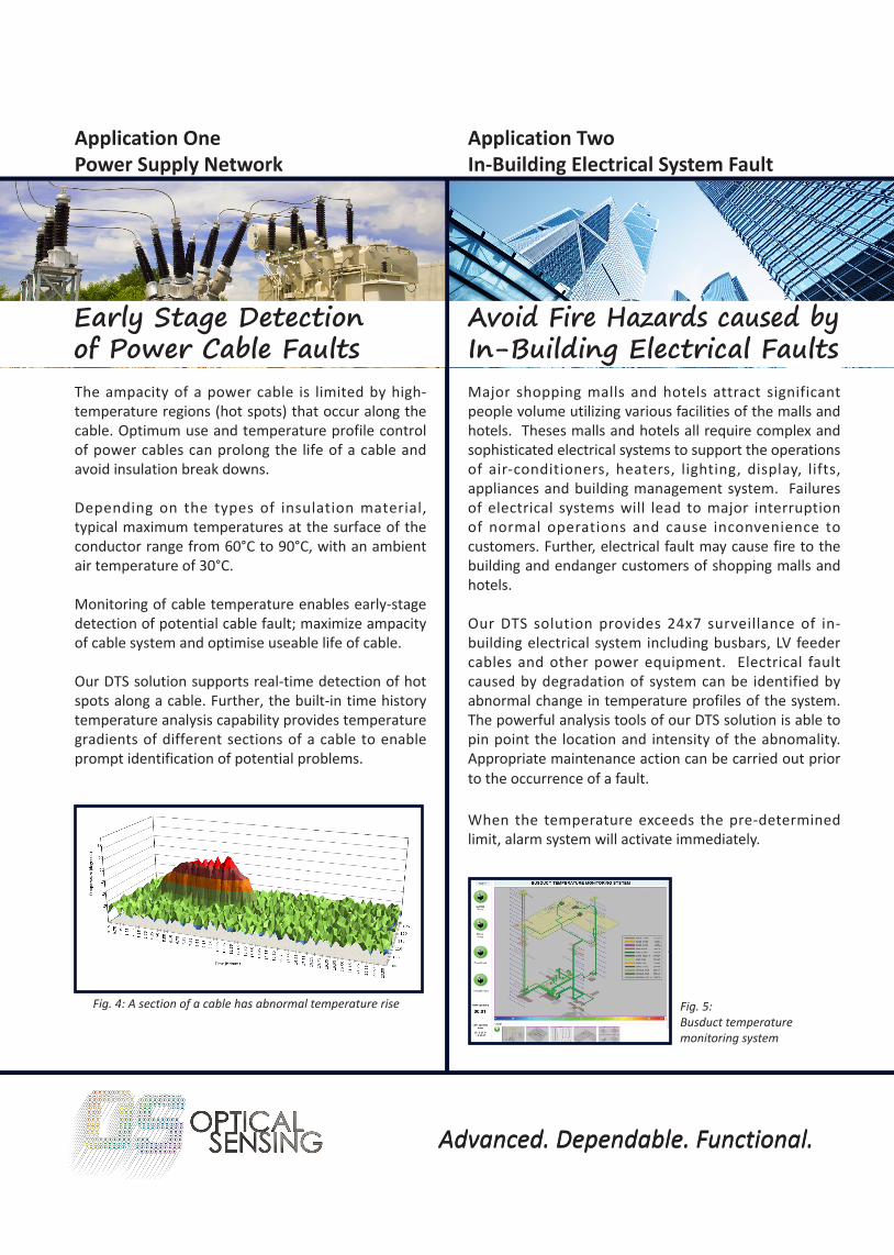
The Raman backscattering components are caused by thermally influenced molecular vibrations from the propagating light pulse. Thus, their intensity depends on temperature. The Raman backscattered light have two components that lie symmetric to the Rayleigh peak: the Stokes peak and Anti-Stokes peak.
The Raman Anti-Stokes Band ComponentsThe Intensity (IAS) correlates to temperature. The time of flight of the backscattered light provides information on distance travelled and hence the location of the temperature point.
Fig. 2: The technology of FODTS
Fig. 3: The Raman backscattering components
Advanced. Dependable. Functional.Advanced. Dependable. Functional.
Application OnePower Supply Network
Application TwoIn-Building Electrical System Fault
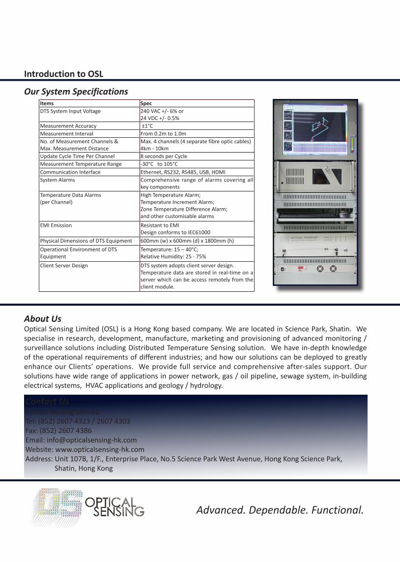
The ampacity of a power cable is limited by high-temperature regions (hot spots) that occur along the cable. Optimum use and temperature profile control of power cables can prolong the life of a cable and avoid insulation break downs.
Depending on the types of insulation material, typical maximum temperatures at the surface of the conductor range from 60°C to 90°C, with an ambient air temperature of 30°C.
Monitoring of cable temperature enables early-stage detection of potential cable fault; maximize ampacity of cable system and optimise useable life of cable.
Our DTS solution supports real-time detection of hot spots along a cable. Further, the built-in time history temperature analysis capability provides temperature gradients of different sections of a cable to enable prompt identification of potential problems.
Major shopping malls and hotels attract significant people volume utilizing various facilities of the malls and hotels. Theses malls and hotels all require complex and sophisticated electrical systems to support the operations of air-conditioners, heaters, lighting, display, lifts, appliances and building management system. Failures of electrical systems will lead to major interruption of normal operations and cause inconvenience to customers. Further, electrical fault may cause fire to the building and endanger customers of shopping malls and hotels.
Our DTS solution provides 24x7 surveillance of in-building electrical system including busbars, LV feeder cables and other power equipment. Electrical fault caused by degradation of system can be identified by abnormal change in temperature profiles of the system. The powerful analysis tools of our DTS solution is able to pin point the location and intensity of the abnomality. Appropriate maintenance action can be carried out prior to the occurrence of a fault.
When the temperature exceeds the pre-determined limit, alarm system will activate immediately.
Fig. 4: A section of a cable has abnormal temperature rise Fig. 5: Busduct temperaturemonitoring system
Early Stage Detection of Power Cable Faults
Avoid Fire Hazards caused by In-Building Electrical Faults

Advanced. Dependable. Functional.Advanced. Dependable. Functional.
Application ThreeOil & Gas Industries
The inherited continuous sensing ability of DTS makes it the ideal solution to quickly detect leak events by monitoring the temperature profile along the complete length of pipeline.
For gas line, the escape pressurised gas produces a local cold zone at the surface of the leaked pipe due to Joule-Thompson effect. The change in temperature at the leaked location is immediately detected and measured by our DTS solution to locate precisely the leak.
Oil pipeline leak will however result in a rise in temperature at the point of leak.
In both cases, our DTS solution is able to preciously identify the leak location promptly thereby saving significant cost of leak and time in identification of leak location.
Gas & Oil Pipeline Leak Detection
Application FourHeating Ventilation Air Conditioning (HVAC)
Effective tunnel ventilation is necessary to bring fresh air to passengers at the stations and inside the trains. Tunnel temperature monitoring and control enable the operator to optimise the air-flow volume and temperature in the tunnel. The underground railway ventilation system comprises of Ventilation Shafts (above ground structure) which serves as Inlets and Outlets for air movement. A schematic diagram of the tunnel ventilation system is illustrated in Fig. 7.
Why use DTS to monitor?DTS fibre optic cable is cost effective, immune to interferences in the tunnel & basically maintenance free;
DTS provides 24x7 monitoring of tunnel temperature and store up to 1-year data for further analysis;
Our DTS can integrate with tunnel ventilation control system to provide full feedback control system supporting both real-time environment data and time-series trend analysis data.
Tunnel Temperature Monitoring & Ventilation Control
installation location of DTS FO Cables
Ventilation Shaft Ventilation Shaft
Air Inflow Air Outflow
DTS Fibre Optic Cables - attached at different heights of tunnel
Fig. 6: DTS solution for gas pipeline leak detection
Fig. 7: DTS solution for tunnel temperature monitoring
Ground Level
DTS Fibre Cable2130m
Burst in pipeline
DTS Temperature - distance plot
Tem
pera
ture
(deg
ree
°C)
Distance (m)
Drop in temperature at leak location

Advanced. Dependable. Functional.Advanced. Dependable. Functional.
Application FiveWater Supply & Waste Water System
Application SixHydrology and Geology
DTS has a wide range of applications in hydrology and geology.
Measurement of temperature is always necessary in geological and hydrological processes. In most applications, it is required to measure gradients in temperature in time and space.
Governments, Universities and Research Institutions have used DTS to successfully collect temperature data from various geological and hydrological locations including lake, river, underground water streams and surface water streams.
Water temperature is of importance to ecological processes. DTS fibre cable installed along the river provides unprecedented precision and resolution of temperature readings along the river.
Examples of applications- Understanding and monitoring of stream-aquifer;- Understanding of estuary-aquifer interaction;- Surveillance of aquatic environments;- Computation of energy balance for evaporative loss;- Tracing of convection process;- Understanding of fractured-aquifer hydraulics in boreholes
Storm water is produced from rain (mainly) and sprinklers or other means, that falls and is transported over road / pavement surface into local storm water drain. The storm water will be finally discharged into river, stream or sea. The discharged storm water is UNTREATED.
Waste water is any type of water that have been utilised and the utilisation has adversely affected the quality of water. Examples are water that is discharged from households (sanitary), offices and industries. Waste water typically is TREATED before it is discharged.
Ideally storm water and waste water must be separated. If waste water runs into storm water dra inage system, then i t wi l l cause ser ious environmental and health hazards.
DTS solution has been widely used to detect illicit connections in storm sewer systems. The continuous temperature measurements along the in-sewer fibre optic cable creates a detailed representation of temperature anomalies due to illicit discharges.
Fig. 8: DTS solution for illegal disposal of waste water
Hydrology & Geology
Water Supply & Waste Water System
Illegal disposal of waste water
Storm water pit
Illegal waste water causes rise in temperature
Storm water pipe
Sewage water pipe
DTS fibre optic cable
Fig. 9: DTS fibre optic cable along a river
Advanced. Dependable. Functional.
About UsOptical Sensing Limited (OSL) is a Hong Kong based company. We are located in Science Park, Shatin. We specialise in research, development, manufacture, marketing and provisioning of advanced monitoring /surveillance solutions including Distributed Temperature Sensing solution. We have in-depth knowledge of the operational requirements of different industries; and how our solutions can be deployed to greatly enhance our Clients’ operations. We provide full service and comprehensive after-sales support. Our solutions have wide range of applications in power network, gas / oil pipeline, sewage system, in-building electrical systems, HVAC applications and geology / hydrology.
Contact UsOptical Sensing LimitedTel: (852) 2607 4323 / 2607 4303Fax: (852) 2607 4386Email: [email protected]: www.opticalsensing-hk.comAddress: Unit 107B, 1/F., Enterprise Place, No.5 Science Park West Avenue, Hong Kong Science Park, Shatin, Hong Kong
Introduction to OSL
Items SpecDTS System Input Voltage 240 VAC +/- 6% or
24 VDC +/- 0.5%Measurement Accuracy ±1°CMeasurement Interval From 0.2m to 1.0mNo. of Measurement Channels & Max. Measurement Distance
Max. 4 channels (4 separate fibre optic cables)4km - 10km
Update Cycle Time Per Channel 8 seconds per CycleMeasurement Temperature Range -30°C to 105°CCommunication Interface Ethernet, RS232, RS485, USB, HDMISystem Alarms Comprehensive range of alarms covering all
key componentsTemperature Data Alarms (per Channel)
High Temperature Alarm; Temperature Increment Alarm; Zone Temperature Difference Alarm; and other customisable alarms
EMI Emission Resistant to EMIDesign conforms to IEC61000
Physical Dimensions of DTS Equipment 600mm (w) x 600mm (d) x 1800mm (h)Operational Environment of DTS Equipment
Temperature: 15 – 40°C; Relative Humidity: 25 - 75%
Client Server Design DTS system adopts client server design.Temperature data are stored in real-time on a server which can be access remotely from the client module.
Our System Specifications

All rights reserved. No part of this company profile may be reproduced or transmitted in any form or by any means, electronic or mechanical, including photocopying, recording, or by an information storage and retrieval system without written permission from Optical Sensing Ltd.
OSLPB201311