The UKCCSRC Pilot-scale Advanced Capture Technology (PACT ... · The UKCCSRC Pilot-scale Advanced...
31
UK CCS/CCUS Efforts The UKCCSRC Pilot-scale Advanced Capture Technology (PACT) Test Center April 28-May 1, 2014 David L. Lawrence Convention Center Pittsburgh, Pennsylvania Presented at the Thirteenth Annual Conference on Carbon Capture, Utilization & Storage Jon Gibbins*, Mohamed Pourkashanian + , Karen Finney + , Mathieu Lucquiaud* and Kris Milkowski + UK CCS Research Centre and UKCCSRC PACT *University of Edinburgh, + University of Leeds
Transcript of The UKCCSRC Pilot-scale Advanced Capture Technology (PACT ... · The UKCCSRC Pilot-scale Advanced...

UK CCS/CCUS Efforts
The UKCCSRC Pilot-scale Advanced Capture Technology(PACT) Test Center
April 28-May 1, 2014
David L. Lawrence Convention Center
Pittsburgh, Pennsylvania
Presented at the Thirteenth Annual Conference on Carbon Capture, Utilization & Storage
Jon Gibbins*, Mohamed Pourkashanian+, Karen Finney+, Mathieu Lucquiaud* and Kris Milkowski+
UK CCS Research Centre and UKCCSRC PACT*University of Edinburgh, +University of Leeds

M. PourkashanianDirector, UKCCSRC-PACT www.pact.ac.uk
J. GibbinsDirector, UKCCSRC www.ukccsrc.ac.uk

The Energy Innovation Processhttp://www.energyresearchpartnership.org.uk/Innovation+Landscape

About PACT• Pilot-scale Advanced Capture Technology facilities
– Funded jointly by the EPSRC and DECC – Partners: Cranfield, Edinburgh, Imperial, Leeds, Nottingham, Sheffield– Part of the UK Carbon Capture & Storage Research Centre
(UKCCSRC)• Scope: Specialist national facilities for research in advanced fossil-
fuel energy, bioenergy and carbon capture technologies– Comprehensive range of pilot-scale facilities – Specialist research and analytical facilities – Supported by leading academic expertise
• Aim: Catalyse and support industrial and academic research to accelerate the development and commercialisation of novel technologies
• Objectives– Bridge gap between bench-scale R&D and industrial pilot trials– Provide shared access to industry and academia


PACT Locations
• 3 Facility Sites • PACT Office

Edinburgh PACT Facilities
• Advanced Capture Testing in a Transportable Remotely- Operated Mini-lab (ACTTROM)
• Integrated, mobile carbon capture media testing laboratory
• Designed for long-term on- site testing of CO2 capture media on real flue/process gases with a possibility of multiple parallel tests
• Facility is transported to the test site and connected directly to onsite flue/process gases
• Remotely monitored and operated by University of Edinburgh
• About to go on site
• ACTTROM–Aids technology development and
scale-up for technology developers –Provides site-specific operational data
to operators, for example, in advance of the deployment of a specific capture system

Cranfield PACT Facilities
• PACT is part of new energy facilities at Cranfield
• 750kWth Burner Rig for Gas Turbine Hot Gas Path Research
• 350kWth Circulating Fluidised Bed Facility
• 50kWth Chemical/Calcium Looping Facility
• 150kWth Pulverised Fuel rig
• Dense-phase CO2 Flow Loop Rig

PACT Core Facility

PACT Plant Interconnections

250kW Air Combustion Plant

250kW Air/Oxy Combustion PlantOverview• ~250kWth, 4.5m high; 0.9m radius, cylindrical,
down-fired rig with 8 sections • Fuel: Coal, Biomass, Co-firing, Gas (primarily preheating)• 2 x (interchangeable) coal/biomass burners - scaled
from Doosan Power Systems commercial low-NOx burners• Dedicated, high precession air metering skid • Flue gas candle filter ( >99% ash removal); • Furnace pressure (negative) balanced by exhaust fan• Temperature and flow monitored water cooling system for
the combustion rig, flue gas duct and heat exchanger.• SCADA operating system with internet monitoring

Periodic meshCAD 3D mesh
250kW Air/Oxy Combustion Plant

Air‐coal 200 kW with preheated
air
z = 75mm
r = 0 mm
≈40
00mm
z = 0mm
≈
900mm
Temp.[C]1500
1300
1100
900
700
500
300
100
RANS, temp contour.
250kW Air/Oxy Combustion Plant

Air-coal 200 kW with preheated air

250kW Air/Oxy Plant
• In-flame temperature profiles using suction pyrometry
• Heat flux profiles using an ellipsoidal radiometer and total heat flux probes
• Laser Induced Fluorescence (LIF)
• In-flame and exhaust species profiles
•
3D Particle Image Velocimetry
(PIV), Laser Doppler Velocimetry
(LDV);•
Flame characterisation, including
shape, luminosity, and frequency, using 2D and 3D flame imaging with photographs and videos as well as computer tomographic
reconstruction of the
flame in 3D•
Particle velocity profiles within the top section of the furnace
(for both non‐
reactive and reactive species)
3D laser diagnostics and thermal imaging

1200°C
1450°C
1350°C
1300°C
1250°C
1600°C
1500°C
1400°C
1550°C
200kWth air coal combustion (benchmark simulation)
2D flame imaging by Kent University1
Instantaneous experimental
temperature distributionInstantaneous image
1Experimental Images and data courtesy of Kent University
LES instantaneous
temperature distribution
Experiments LESFlicker (Hz) 6 - 9 5.3
Flicker study
250kW Air/Oxy Combustion Plant

Air Oxy21
Oxy25 Oxy30
Theoretical study of flame flicker for
air & oxy at 250 kWth
Flicker study
250kW Air/Oxy Combustion Plant
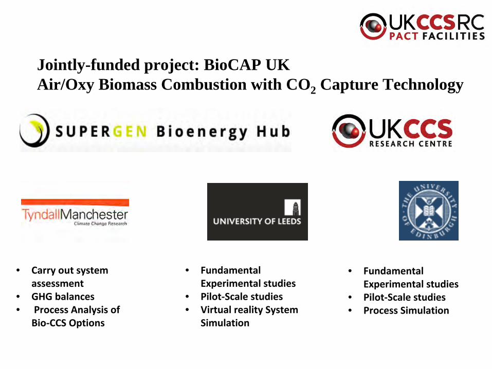
• Carry out system
assessment • GHG balances• Process Analysis of
Bio‐CCS Options
• Fundamental
Experimental studies• Pilot‐Scale studies• Virtual reality System
Simulation
• Fundamental
Experimental studies• Pilot‐Scale studies• Process Simulation
Jointly-funded project: BioCAP UKAir/Oxy Biomass Combustion with CO2 Capture Technology

BioCAP UK Impact•The project will remove some of the significant technical barriers to bio-CCS development. •It will progress current understanding of the potential of bio-CCS for the UK energy system so that realistic projections of deployment, costs and achievable GHG reductions can be incorporated in policy development. •The project will accelerate UK development of bio-CCS technology •The project will consolidate the UK’s position as world-leaders in technology understanding for decarbonisation of existing coal based power generation infrastructure

Applications• Testing & development of alternative solvents• Benchmarking & energy requirements• Solvent degradation & enhancement studies • Real aged solvents assessment• Plant and system modelling • Assessment of plant flexibility and performance with
different fuels (e.g. biomass) or other conditions• Integrated systems modelling and control• Validation of baseline economics
Solvent-based CO2 Capture Plant

UKCCSRC-PACT Gas Turbine+ Amine Plant

Lean Flow (kg/h) Rich Flow (kg/h) Lean Ldg (mol/mol) Rich Ldg (mol/mol)
Experimental Modelling Experimental Modelling Experimental Modelling Experimental Modelling
515 515 531 538 0.25 0.23 0.41 0.40
Key Simulation/Experimental Results
MEA Solvent, Flue Gas CO2 Level = 7%
CO2 Cap (kg/h) CO2 Cap (%) Reb Duty (MJ/kg CO2)
Experimental Modelling Experimental Modelling Experimental Modelling
16.45 16.45 76.3 76.3 5.92 5.69

Absorber Temperature ProfileABSORBER Rate-Based M odeling - Interface Profiles Temperat ures
Stage
TEM
PERA
TURE
C
1 2 3 4 5 6 7 8 9 10 11 12 13 14 15 16 17 18 19 2036
38
40
42
44
46
48
50
52
54
56
Liquid TemperatureVapor Temperature

Gas Turbine SystemOverview• Two Turbec T100 Microturbines• Consume 330kW of Natural gas • Fuel: Natural gas, biogas, syngas,
diesel, kerosene, methanol, LPC• Generation 100kWe and 150kWth • Overall efficiency up to 77% (33%
electrical)

Gas Turbine System Gas Turbine System
GT +(amine) Solvent Based Carbon Capture Plant = Post combustion Capture from Gas Turbine System
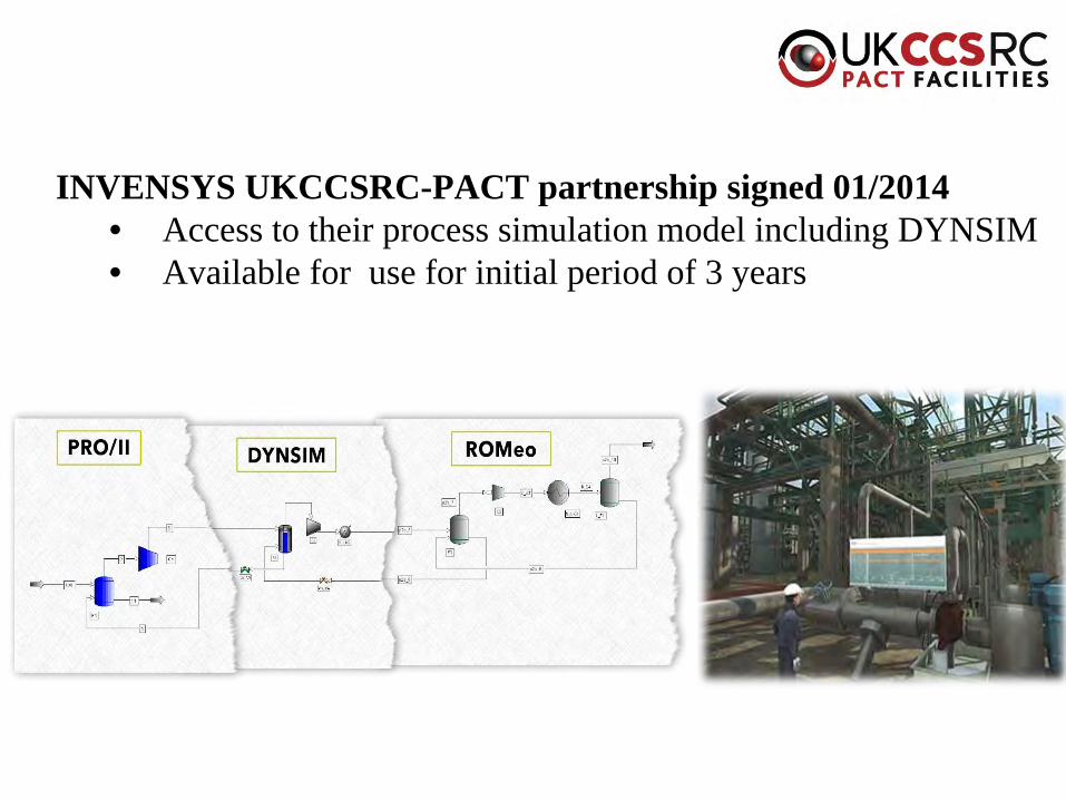
INVENSYS UKCCSRC-PACT partnership signed 01/2014• Access to their process simulation model including DYNSIM• Available for use for initial period of 3 years

Technical Challenges (1) Case Study: Didcot Power Station A
Air Oxy25 Oxy30
Coal Biomass
Air Oxy25 Oxy30

Technical Challenges (2) Case Study: Didcot Power Station A

Analytical Facilities: Labs• Analytical labs• Unique Continuous Emission Monitoring
mobile laboratory for solid-state detector based ICP-OES (SUWIC)
• Cambustion DMS500 Fast particulate analyser
• CHNS/O Elemental Analyser• GC MS and TG-MS• Thermogravimetric Analyser and TG-
MS• FT-IR and TG-IR• Portable SERVOFLEX MiniMP gas
analysers (CO2 and O2 )

Overview & Contacts• Comprehensive research capability and support• Consolidating a wide range of facilities and supporting expertise• Maximising equipment utilisation through shared access to industry and
academia • Services
– R&D Services • Collaborative research • Contract research
– Analytical services – Technical consultancy – Training