PACT - Pilot Scale Advanced Capture Technology & Biomass ...
24
Energy Technology & Innovation Initiative Faculty of Engineering PACT - Pilot Scale Advanced Capture Technology & Biomass/Bioenergy Combustion Test Facilities Available For Industry & Academia M. Pourkashanian Director PACT National Facilities, UK PACTFACILITIES UKCCSRC
Transcript of PACT - Pilot Scale Advanced Capture Technology & Biomass ...

Energy Technology & Innovation Initiative Faculty of Engineering
PACT - Pilot Scale Advanced Capture Technology & Biomass/Bioenergy
Combustion Test Facilities Available For Industry & Academia
M. Pourkashanian Director
PACT National Facilities, UK
PACTFACILITIES
UKCCSRC

Large scale Shared Facilities for CCS Capture and Biomass/Bioenergy Combustion technologies
• EPSRC Delivery Plan: Internationally-leading engineering and physical sciences research cannot be done without access to large-scale infrastructure, facilities and equipment.
• For the future it has been agreed that it may be preferable to support fewer facilities in a more sustainable way rather than more facilities at a sub-optimal level.
• Encourage research facilities to provide complementary services to industrial users (where there is a market), thereby securing leverage on public investment, the profit from which will be reinvested into service improvements for all users.
• Reform provision of equipment with a national prioritisation of needs. We will increase the strategic use and sharing of capital items working in partnership with universities.

Pilot scale Shared Facilities for CCS Innovation (Capture technologies) & Biomass, Biofuel Combustion
• DECC funding on establishing facilities to support CCS innovation and technology development
• The facilities will become part of the broader UK Centre for CCS umbrella. • Pilot-Scale Advanced Capture Technology (PACT Facilities)
to support CCS innovation. • PACT Consortium: Edinburgh, Cranfield, Imperial,
Nottingham, Sheffield and LEEDS • PACT present a strong, multidisciplinary partnership of
leading CCS researchers with an international profile in the field

The role and added value of large-scale CCS (Capture) and Biomass, Biofuel research
facilities
• Positive impact on the reputation of research groups, research centre, hubs, and even whole research fields.
• Exponential increase in the number of observations and experiments via linking to a large infrastructure network.
• Contribution to a more efficient way of working. • Achieving the set scientific goals within a given time. • Combining and integrating complex, linked research. • Improving UK/EU competitiveness . • Existing funding structures for large-scale facilities.

UKCCSRC-PACT Facilities
• The following categories of users are identified: – UK/EU academics – including those from Research
institutes, The RS and RAE fellowships and UK Postdoctoral Researchers
– UK/EU Academics with EU Projects – The level of access in accordance with agreed EU funding levels.
– International Agreements –(contractual access agreements ).
– Other International Users – (world class RD&D). – Commercial and Contractual Users – (SMEs). – Private Sector Access – in collaboration with UK
academic partner (open literature publications).

Location for PACT Core Facilities
2 miles from M1, junction 31 Leeds airport = 30 miles
Manchester International Airport = 45 miles

Gas Turbine APU/Micro Turbine 250 kW/15 kW EGR/HATGT
IGCC 250 kW Oxy-fuel CTF 250KW
Coal-Biomass FB 250kW
Combustion Test Facilities 250kW Coal/biomass
UK CCS Research Pilot-Scale Advanced Capture
Technology (PACT) Facilities
Gas Mixing System 200kW
Amine Capture Plant 150kW
RWE facilities

System Fuel Oxidizer CO2 Capture
Oxy-Fuel Combustion Test Facilities 250KW Down fired Gas Cleaning
1. Coal 2. Biomass 3. Blend
a. Air b. Oxygen c. Oxidiser via Gas Mixing System d. EGR (wet) e. EGR (Dry)
i. Oxyfuel ii. Post-combustion via
Amine Plant
CTF Air-Fuel 1. Coal 2. Biomass 3. Blend
a. Air b. Oxygen c. Oxidiser via Gas Mixing System
ii. Post-combustion via Amine Plant
FB-Air-Oxygen 1. Coal 2. Biomass 3. Blend
a. Air b. Oxygen c. Oxidiser via Gas Mixing System d. EGR (wet) e. EGR (Dry)
ii. Post-combustion via Amine Plant
Planned Gasifier 1. Coal 2. Biomass 3. Blend
a. Air b. Oxygen c. Oxidiser via Gas Mixing System d. EGR (wet) e. EGR (Dry)
iii.Pre-combustion via Shift Unit
Gas Turbine 4. Natural gas 5. Syngas 6. H2-rich syngas
a. Air c. Oxidiser via Gas Mixing System d. EGR (wet) e. EGR (Dry)
ii. Post-combustion via Amine Plant

UK CCS Research Pilot-Scale Advanced Capture Technology (PACT) Facilities
Amine Post Combustion
Capture Plant (150 KW)
Coal
S
B
C
G
Control Units & System
Integration
Oxygen
Coal
Biomass
AIR
Natural Gas
Gas Turbine APU & Turbec 150Kw
Oxy/air-Solid
Fuels CTF with EGR 250KW
Coal – Biomass
blend Fuels 50KW
Coal – Biomass Air/Oxy
FB Reactor 150KW
Gas Mixer Facilities
Up to 250 KW
O
L
Planned IGCC
Reactor (200 KW)
R
Gas Cleaning
and Shift
System Monitoring
Via Internet
R
E
E
M
A E
E

UKCCS Research Pilot-Scale Advanced Capture Technology (PACT) Facilities
Amine Post Combustion
Capture Plant (150 KW)
Coal
S
B
C
G
Control Units & System
Integration
Oxygen
Coal
Biomass
AIR
Natural Gas
Gas Turbine APU & Turbec 150Kw
Oxy/air-Solid
Fuels CTF with EGR 250KW
Coal – Biomass
blend Fuels 50KW
Coal – Biomass Air/Oxy
FB Reactor 150KW
Gas Mixer Facilities
Up to 250 KW
O
L
Planned IGCC
Reactor (200 KW)
R
Gas Cleaning
and Shift
System Monitoring
Via Internet
R
E
E
M
A E
E

UK CCS Research PACT Facilities Pilot-Scale Advanced Capture Technology
Amine Post Combustion
Capture Plant (150 KW)
Coal
S
B
C
G
Control Units & System
Integration
Oxygen
Coal
Biomass
AIR
Natural Gas
Gas Turbine APU & Turbec 150Kw
Oxy/air-Solid
Fuels CTF with EGR 250KW
Coal – Biomass
blend Fuels 50KW
Coal – Biomass Air/Oxy
FB Reactor 150KW
Gas Mixer Facilities
Up to 250 KW
O
L
Planned IGCC
Reactor (200 KW)
R
Gas Cleaning
and Shift
System Monitoring
Via Internet
R
E
E
M
A E
E
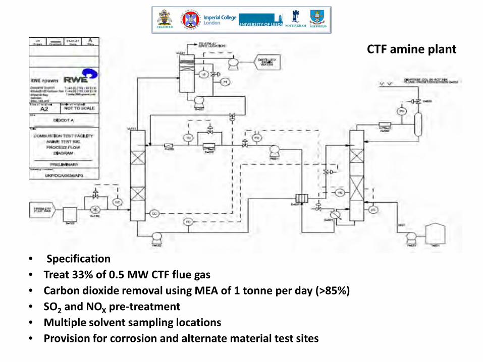
• Specification • Treat 33% of 0.5 MW CTF flue gas • Carbon dioxide removal using MEA of 1 tonne per day (>85%) • SO2 and NOX pre-treatment • Multiple solvent sampling locations • Provision for corrosion and alternate material test sites
CTF amine plant

Test programme • MEA reference tests
with heat and material balances and parametric studies
• Alternative solvents e.g. MDEA, hindered amines
• Validation of baseline process economics and assessment of plant flexibility
CTF amine plant

Amine Plant Design • Test rig performance modelled using Promax
software • Flue gas treated: 230 m3/h (263 kg/h) • Amine circulation rate of 1 m3/h • Absorber: 300mm diameter, 6m packing
height, 8m overall height • Desorber: 300mm diameter, 6m packing
height, 8m overall height CO2 Profile Across Desorber
CO2 Gas From
Desorber
CO2 in Reboiler
Oulet
CO2 Inlet
0.00
0.50
1.00
1.50
2.00
2.50
kmol
/hr C
O2
Predicted Desorber CO2
Liberation Efficiency = 52.9%
Amine Absorber CO2 Content In Gas
Inlet
Outlet
0.00
0.20
0.40
0.60
0.80
1.00
1.20
1.40
kmol
/hr C
O2
Predicted CO2
Removal Efficiency = 91%
Estimated Power Requirements Service Power (kW)
Booster Fan 4 Pumps 4.5
Hot Water Package 78 Air Condenser 2
Total 88.5

• Oxy-Coal/Biomass Combustion Test Facilities
• Air-Coal/Biomass Combustion Test Facilities
• FGR (Wet and Dry) + Gas Mixing Facilities

Gas Turbine Facilities with EGR + HAT Fuel Flexibility: NG, Biogas, Biofuel & H2 Enriched Gas

Gas Turbine Facilities with EGR + HAT Fuel Flexibility: NG, Biogas, Liquid Fuel, Biofuel & H2 Enriched Gas

THE T100 GAS TURBINE • The Turbec T100 is a
recuperative gas turbine, consisting of:
• Centrifugal compressor stage and a radial expander stage, generating 100 kW electricity with an electrical efficiency of ca. 30%.
• The turbine is also equipped with a heat exchanger, recovering the exhaust heat after the recuperator, to produce hot water.

Exhaust gas recycle (EGR & EGSR) Non-Selective Recycle in CCGT for
CO2 Capture (EGR) • Exhaust gas recycle (EGR) is an
established concept for increasing the CO2 concentration in the flue gas
Selective Recycle in CCGT for CO2 Capture (EGSR)
• Substantial improvements can be achieved when selective CO2 recycle from flue gas to the gas turbine is used

ACTTROM • Testing Solvents and solid materials
for CO2 capture for many months to get same levels of degradation that will occur on real plants.
• expensive on a pilot-scale unit for a single test.
• multiple tests are required to cover ranges of possible operating conditions, solvent blends etc.
• A number of small-scale test units from different UKCCSRC partners to be run on power plant sites using real flue gases.
• The unit run unattended for up to a month between servicing and sample collection visits
ACTTROM
Advanced Capture Testing in a Transportable Remotely-
Operated Mini-lab

• PACT Interactive Website (October 2012) – Description/specifications of facilities – Working with PACT (Collaborative Mission)
• Academic Institutions • Visiting Researcher and Visiting Programme • Industrial partnership • SMEs
– PACT Events/workshops/training – PACT Open Access Database – Members login for Real Time Test Data Monitoring – PACT Access – Outreach – PACT Blog
• Launch Date: 09/2012

PACT Office for Visitors & Collaborators • Availability of all commercial CFD, Process, Techno-economic, Visualization Soft wares • Easy access to PACT experimental facilities • Excellent environment for visiting researchers

• Industry-PACT Partnership & Engagement
– Shaping the Future: To Advance Next-Generation Capture and Biomass/Biofuel combustion Technologies.
– Issues and Challenges: Access to ideas, projects, experts and institutions.
– Focus on high growth and innovative SMEs and Focus on high-value opportunities
• “Get Involved” Campaign – To seek industry partners who will work with PACT to define
new projects relevant to their business aims. – Participation in the PACT facilities will provide a cost-effective
means of supporting high quality, applied R&D that is directly relevant to company’s development challenges.

Energy Technology & Innovation Initiative Faculty of Engineering
PACTFACILITIES
UKCCSRC
www.ukccsrc.ac.uk www.ukccsrc-pact.leeds.ac.uk (15/07/2012)