Compendium of Belgian IT Laws (2005): privacy, monitoring and outsourcing
114 IT Compendium
IT has created a world of its own. Even specially trained experts don’t
sometimes know the answer to specific questions. A browse through
the transtec IT Compendium can help. Here you can find detailed
information which is easy to understand and clearly presented. And for
any questions that couldn’t be answered in the Magalogue, you can
visit our online archive of the IT Compendium at www.transtec.co.uk,
www.ttec.nl and www.ttec.be.
The transtec IT Compendium:Know-How as it happens.

1. Computer Architectures
2. Operating Systems
3. Clusters
4. Storage Buses
5. Hard Disks and RAIDs
6. Storage Networks
7. Magnetic Tape Storage
8. Optical Storage
9. Working Memories
10. Communication
11. Standards
12. The OSI Reference Model
13. Transfer Methods and Techniques
14. Personal Area Networks – PANs
15. Local Area Networks – LANs
16. Metropolitan Area Networks –MANs
17. Wide Area Networks - WANs
18. LAN Core Solutions
19. Input Devices
20. Data Communication
21. Terminals
22. Output Devices
23. Multimedia
24. Uninterruptible Power Supplies
in the IT Compendium on pages 116–141
online on our homepage
115IT Compendium

Computer Architectures · Operating Systems
1. Computer Architectures
1.3 PCI-Express
PCI-Express (PCIe) is the successor to ISA and PCI. This interconnect
technology was also formerly known as 3GIO for 3rd Generation I/O,
a term coined by Intel®. Similar to the transition from Parallel ATA to
Serial ATA, for example, the higher speeds are achieved by the succes-
sive transfer of serialised PCI information. The reason behind this
seemingly paradoxical state is that parallel routed data packets must
arrive at the receiver buffer within a short time frame. Due to varying
impedance levels and cable lengths, this stands in the way of a further
increase in the frequency in the high Megahertz sector. PCI-Express
has however perfected the serial transfer in the Gigahertz sector.
The PCIe link is built around an individual point-to-point connection
known as a “lane”. PCI-Express achieves per connection a data trans-
fer rate of 2.5 Gbit/sec. As it utilizes the 8 B/10 B encoding scheme,
an effective transfer rate of 250 Mbyte/sec. is possible. All connec-
tions offer full duplex operation.
These lanes can be interleaved, a common feature of other similar
serial interconnect systems (e.g. InfiniBand). The PCI-Express can sup-
port a maximum of 32 lanes. In real applications, PCIe with 16 lanes is
a popular alternative to the AGP slot whereby 8x and 4x PCIe are used
in the server sector. The slots offer downwards compatibility enabling
a 1x card to be used in a 8x slot.
All of the standard PCI protocols have remained unchanged. Besides
copper cables, optical connections are also specified as standard. In
principle, PCI-Express supports hot-plug operation. However, it is un-
usual to find solutions involving the inserting and unplugging of inter-
face cards during operation with the x86 server.
1.3.1 HyperTransport and HTX
HyperTransport (HT) is a universal, bi-directional broadband bus system
which is set to replace the currently available proprietary buses. The
HyperTransport standard is an open, board-level architecture designed by
the HyperTransport Consortium as a manufacturer-independent system.
HyperTransport is software compatible to PCI so that simple and
efficient chipsets suffice to connect PCI I/O cards. HyperTransport
also employs serial point-to-point links. The electrical interface is based
on LVDS (Low Voltage Differential SCSI) using 1.2 Volt voltage. The
clock rate is between 200 and 800 MHz. 1600 Mbit/sec. can be
achieved per link by employing DDR data transfer (Double Data Rate,
i.e. sending data on both rising and falling edges).
A standard aggregation of up to 32 links was planned. In practise,
however, the current maximum is 16 links. Up to 6.4 Gbyte/sec. are
transferred via 16 links with an AMD OpteronTM.
A packet-based protocol is used to avoid control and command lines.
Regardless of the physical width of the bus interconnect, each packet
always consists of a set of 32 bits words. The first word in a packet
is always a command word. If a packet contains an address, the last
8 bits of the command are chained to the next 32 bits word to make
a 40 bits address. The remaining 32 bytes in a packet are the data
payload. Transfers are always padded to a multiple of 32 bits.
HyperTransport is currently used by AMD, NVIDIA or Apple. Besides
interconnecting processors over a fast backbone bus, they can also be
employed in routers or switches.
In the HTX connector, the HyperTransport bus is built around 16 lanes
and can be used by fast interconnects such as InfiniPath.
116 IT Compendium

HyperTransport User Packet Handling
1.1.9 Dual/multi-core processors
Dual Core processors are the first step in the transition to multi-core
computing. A multi-core architecture has a single processor package
that contains two or more “execution cores” and delivers – with
appropriate software – fully parallel execution of multiple software
threads. The operating system perceives each of its execution cores as
a discrete processor, with all the associated resources.
This multi-core capability can enhance user experiences in multitasking
environments, namely, where a number of foreground applications
run concurrently with a number of background applications such as
virus protection, data security, wireless network, management, data
compression, encryption and synchronisation. The obvious user bene-
fit is this: by multiplying the number of processor cores, processor
manufacturers have dramatically increased the PC’s capabilities and
computing resources, which reflects a shift to better responsiveness,
higher multithreaded throughput and the benefits of parallel comp-
uting in standard applications.
Intel has been driving toward parallelism for more than a decade now:
first with multiprocessor platforms and then with “Hyper-Threading
Technology“, which was introduced by Intel in 2002 and enables
processors to execute tasks in parallel by weaving together multiple
“threads” in a single-core processor. But whereas HT technology is
limited to a single core using existing execution resources more effi-
ciently to better enable threading, multi-core capability provides two
or more complete sets of execution resources to increase overall com-
pute throughput. Intel also has certain processors that combine the
benefits of Dual Core with the benefits of HT technology to deliver
simultaneous execution of four threads.
2. Operating Systems
More information can be found on our homepage at
www.transtec.co.uk
www.ttec.nl
www.ttec.be.
117IT Compendium
64 bytes data payload
64 bytes
First Segment
User packet
Control packet Data packet
Base HyperTransport Packet Format User Packet
4, 8 or 12 bytes
Optional 4–64 bytes data payload
User Packet Carried in HyperTransport DirectPacketTM Format
Segment N End Segment
64 bytes 4–64 bytes
Start of Message
Bit sec
End of Message
Bit sec
Count + Byte Count
Posted Write
Control Packet64 bytes data payload 4–64 bytes data payload

Clusters
3. Clusters
3.3 Grid: origin and future
The computational capacity of a computer is a resource and, from an
economical perspective, careful consideration should be given to hand-
ling resources. Intelligently deployed resources can generate financial
reward while resources left unexploited represent dead capital.
Distributed computing beyond computation limitations, as employed
in today’s clusters, is just the start of things to come. When computa-
tional and storage capacities are pooled from “normal“ office compu-
ters or entire clusters and can then be accessed from one location,
even the largest computational problems can be solved in no time at
all. The next aim is to network multiple research institutes together in
order to pool the full capacity of execution resources. This type of shar-
ing is referred to as a grid. The term Grid derives from the universal
concept of the power grid, where you can use a plug to gain access to
electric power. Replace electricity with computing power and capacity,
and that is the idea behind grid computing. The plan is to pool to-
gether thousands of cluster systems located throughout the world.
The long-term objective is to network all the computer or cluster
resources such as the computational capacity, storage capacity, infor-
mation and applications. However, for this objective to be realised, the
relevant information first has to be gathered, processed and set down
in the form of standards.
3.3.1 Different types of grid systems
Grid systems can be categorised into two distinctive classes. Certain grid
systems can be classified according to the application level on which they
perform and others according to their size. There are three main sub-
groups in the application category: computational grids, scavenging grids
and data grids. The first and most important subgroup, the computation-
al grids, are generally speaking, pooled cluster systems with the purpose
of sharing their computing performance. They are pooled clusters which
are not restrained by the homogeneity of computing architectures. In the
next category of scavenging grids, resources are expanded by adding
computers that are not primarily used for computer intensive applica-
tions, such as normal office computers. The term scavenging is meant lit-
erally as unused resources are exploited by externals. The third subgroup
of data grids combines existing storage capacities to create one ultra-
powerful data storage system. Such a system is used in CERN, one of the
world’s largest particle accelerator. A large amount of data traffic accu-
mulates at an extremely fast rate in such scientific applications.
The second category is based on the size of systems in the evolution-
ary development process of grid systems (c.f. Figure 1). Four distin-
ctive levels can be distinguished: The first level comprises today’s
cluster systems with very homogeneous computing architectures and
restricted physical expansion. The next level is reserved for Intra Grids.
This level combines multiple cluster systems in departments or com-
panies. The word Grid is already temporarily used in the name of
this level for accounting and calculating functions.
The next implementation level is a combination of multiple Intra Grids
from various companies: the so-called Extra Grids. The computer arch-
itectures on this level are certainly no longer homogeneous. This is
why an independent architecture is essential. Inhomogeneity should
not however be regarded as a problem as it offers a wide range of
possibilities for networked research institutes. The existing resources
Figure 1: Grid system categorisation according to Grid size
can thus be optimally exploited. The Inter Grids form the last level in
this Grid system. The term is closely associated to the word Internet
and rightly so. This grid is vast. Each user has access to the existing
resources whether computational or storage capacities. The authen-
tication and access management control with accounting and moni-
toring functions represent an immense challenge for the management
level. There are already ambitious projects underway, the aim of which
is to create a global grid system. These projects are known as Eurogrid
118 IT Compendium
or TeraGrid. The problem here does not lie in the hardware and soft-
ware but also on the potential conflict of interests of the different
parties involved in the project.
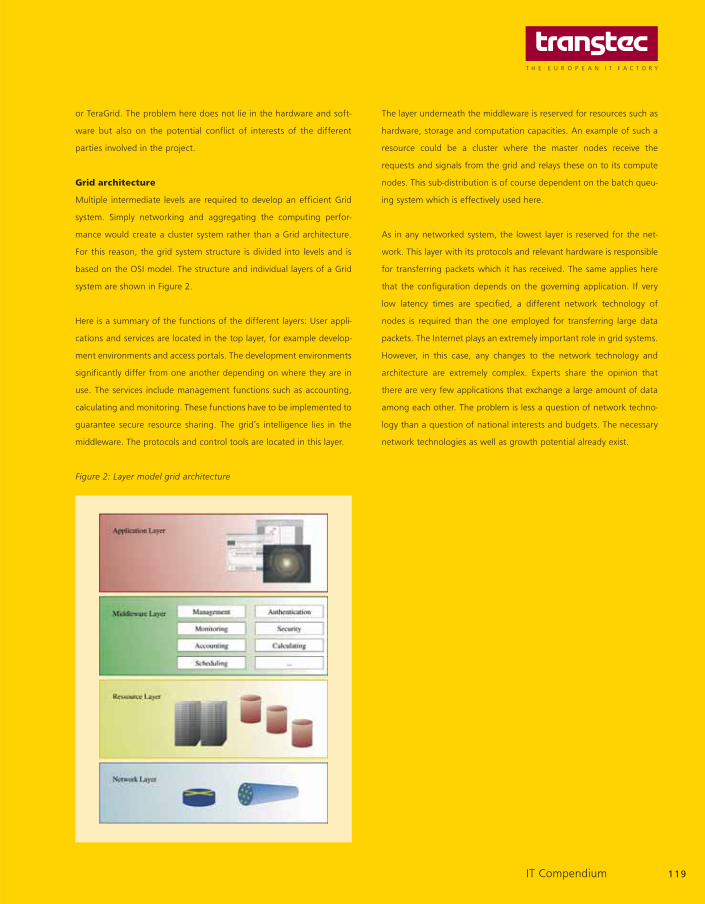
Grid architecture
Multiple intermediate levels are required to develop an efficient Grid
system. Simply networking and aggregating the computing perfor-
mance would create a cluster system rather than a Grid architecture.
For this reason, the grid system structure is divided into levels and is
based on the OSI model. The structure and individual layers of a Grid
system are shown in Figure 2.
Here is a summary of the functions of the different layers: User appli-
cations and services are located in the top layer, for example develop-
ment environments and access portals. The development environments
significantly differ from one another depending on where they are in
use. The services include management functions such as accounting,
calculating and monitoring. These functions have to be implemented to
guarantee secure resource sharing. The grid’s intelligence lies in the
middleware. The protocols and control tools are located in this layer.
Figure 2: Layer model grid architecture
The layer underneath the middleware is reserved for resources such as
hardware, storage and computation capacities. An example of such a
resource could be a cluster where the master nodes receive the
requests and signals from the grid and relays these on to its compute
nodes. This sub-distribution is of course dependent on the batch queu-
ing system which is effectively used here.
As in any networked system, the lowest layer is reserved for the net-
work. This layer with its protocols and relevant hardware is responsible
for transferring packets which it has received. The same applies here
that the configuration depends on the governing application. If very
low latency times are specified, a different network technology of
nodes is required than the one employed for transferring large data
packets. The Internet plays an extremely important role in grid systems.
However, in this case, any changes to the network technology and
architecture are extremely complex. Experts share the opinion that
there are very few applications that exchange a large amount of data
among each other. The problem is less a question of network techno-
logy than a question of national interests and budgets. The necessary
network technologies as well as growth potential already exist.
119IT Compendium

Clusters
3.3.3 Grid information service infrastructure (GIS)
requirements
A grid information service can be a member or a resource in a grid array.
To be able to process the relayed requests, each member must provide
certain capabilities. The Global Grid Forum is an international organi-
sation comprising thousands of members. This organisation specifies
the main resources that a grid information service infrastructure has to
offer:
Efficient reporting of status information of single resources
Error tolerance
Shared components for decentralised access
Services for timestamps and Time-To-Live (TTL) attributes
Query and saving mechanisms
Robust, secure authentication
A short preview to the next chapter now follows: The resources listed
above are taken from the example of the Grid Middleware Globus Toolkit
from Globus Alliance with the help of both the Grid Resource Inquiry
Protocol (GRIP) and Grid Resource Registration Protocol (GRRP). Both
these protocols ensure efficient communication between the Grid Index
Information Service and the Grid Resource Information Service.
3.4. The middleware grid
In the following subchapters, we describe the middleware with refer-
ence to the paper by Ian Foster entitled “The Anatomy of the Grid:
Enabling Scalable Virtual Organizations“ published in 2001. The intel-
ligence of grid systems lies in the middleware. To describe the word
middleware, Ian Foster uses the term “grid architecture“ as the mid-
dleware configures or links the entire grid system and its structure to
be used as a grid . This grid architecture identifies fundamental system
components, specifies the purpose and function of these components
and indicates how these components interact with one another. As
one of the pioneers of grid computing and an active member of
Globus Alliance, Ian Foster explains his definition of grid architecture
on the basis of the Globus Toolkit (GT), which has been developed as
an open source project from Globus Alliance.
3.4.1 Interoperability
One of the most fundamental concerns of the grid architecture is
interoperability. Interoperability is vital if sharing relationships are to be
initiated dynamically among arbitrary parties. Without interoperability,
resources could not be shared and distributed, as they would simply not
be compatible. No virtual organisations could be formed for precisely
the same reason. A VO is a set of multi-organisational parties who share
their resources.
3.4.2 Protocols
Protocols are applied to achieve interoperability. A protocol definition
specifies how system elements interact with one another in order to
achieve a specified behaviour, and the structure of the information
exchanged during this interaction. The focus is thus on externals
rather than internals.
As VOs will complement rather than replace existing institutions, the
only matter of importance is how existing resources will communicate
with each other.
3.4.3 Services
Why are services important? A service is defined solely by the protocol
that it speaks and the behaviours that it implements. The definition of
standard services – for access to computation, access to data, parallel
scheduling and so forth – allows us to abstract away resource-specific
details to help in the development of programs for VOs.
3.4.4 APIs and SDKs
The use of Application Programming Interface (API) and Software
Development Kits (SDKs) enables the dynamic development and
simplified portability of programs for the grid. Users must have the
resources available to be able to operate these programs.
120 IT Compendium

Application robustness and correctness are also improving by means
of a program developed by APIs. In contrast, development and main-
tenance costs are decreasing.
Ian Foster summarizes the above-mentioned conditions: protocols and
services must first be defined before APIs and SDKs can be developed.
3.4.5 Architecture protocol
The neck of the “hour glass” consists of resource
and connectivity protocols. A grid system is ideally
based on Internet protocols as they are standard-
ised and tried and tested. They comply of course
with certain regulations which must be observed.
The main advantage of this existing base is that these protocols
support a diverse range of resource types which have been added over
the years. There are constant developments to the lowest level thus
allowing shared access to multiple hardware. The grid protocol archi-
tecture specified by Ian Foster is shown in Figure 3.
Figure 3: Grid protocol architecture
Fabric layer
The Fabric layer provides resources which can be used by the grid.
These include computational resources, storage systems, catalogues,
network resources and sensors. These resources may be a logical en-
tity, such as a distributed file system or a cluster. For this reason, a
resource implementation may include other external services such as
NFS but these are not the concern of the grid architecture.
Fabric components implement the resource-specific operations that
occur on specific physical or logical resources. It is important to ensure
that minimum operations should be implemented in the lower layers.
This makes it easier to provide more diverse services. For example, effic-
ient reservations of resources can only be achieved if the service is
mapped onto a higher layer. Despite this, there are of course resources
that already support advance reservation on a high level, for example,
clusters.
If these management services – such as the job queuing system in a
cluster – are provided in the resource, they must implement the fol-
lowing requirements to be of use to the grid system. These require-
ments are listed in Table 1 on the following page:
121IT Compendium
Collective
Resource
Structure
Connectivity
Application
Clusters
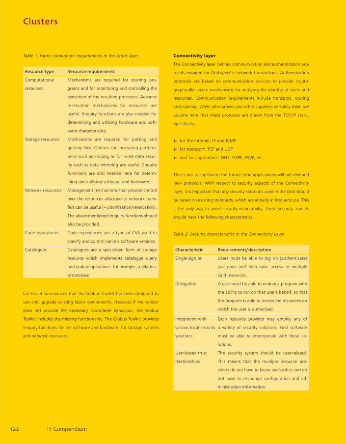
Table 1: Fabric component requirements in the Fabric layer
Resource type Resource requirements
Computational Mechanisms are required for starting pro-
resources grams and for monitoring and controlling the
execution of the resulting processes. Advance
reservation mechanisms for resources are
useful. Enquiry functions are also needed for
determining and utilising hardware and soft-
ware characteristics.
Storage resources Mechanisms are required for putting and
getting files. Options for increasing perform-
ance such as striping or for more data secur-
ity such as data mirroring are useful. Enquiry
func-tions are also needed here for determ-
ining and utilising software and hardware.
Network resources Management mechanisms that provide control
over the resources allocated to network trans-
fers can be useful (= prioritisation/reservation).
The above-mentioned enquiry functions should
also be provided.
Code repositories Code repositories are a type of CVS used to
specify and control various software versions.
Catalogues Catalogues are a specialized form of storage
resource which implements catalogue query
and update operations: for example, a relation-
al database.
Ian Foster summarizes that the Globus Toolkit has been designed to
use and upgrade existing fabric components. However if the vendor
does not provide the necessary Fabric-level behaviour, the Globus
Toolkit includes the missing functionality. The Globus Toolkit provides
enquiry functions for the software and hardware, for storage systems
and network resources.
Connectivity layer
The Connectivity layer defines communication and authentication pro-
tocols required for Grid-specific network transactions. Authentication
protocols are based on communication services to provide crypto-
graphically secure mechanisms for verifying the identity of users and
resources. Communication requirements include transport, routing
and naming. While alternatives and other suppliers certainly exist, we
assume here that these protocols are drawn from the TCP/IP stack.
Specifically:
for the Internet: IP and ICMP
for transport: TCP and UDP
and for applications: DNS, OSPF, RSVP, etc.
This is not to say that in the future, Grid applications will not demand
new protocols. With respect to security aspects of the Connectivity
layer, it is important that any security solutions used in the Grid should
be based on existing standards, which are already in frequent use. This
is the only way to avoid security vulnerability. These security aspects
should have the following characteristics:
Table 2: Security characteristics in the Connectivity Layer
Characteristic Requirements/description
Single sign on Users must be able to log on (authenticate)
just once and then have access to multiple
Grid resources.
Delegation A user must be able to endow a program with
the ability to run on that user’s behalf, so that
the program is able to access the resources on
which the user is authorised.
Integration with Each resource provider may employ any of
various local security a variety of security solutions. Grid software
solutions must be able to interoperate with these so-
lutions.
User-based trust The security system should be user-related.
relationships This means that the multiple resource pro-
viders do not have to know each other and do
not have to exchange configuration and ad-
ministration information.
122 IT Compendium

Grid security solutions should also provide flexible control over the
degree of protection and support for connectionless and connection-
oriented protocols. The following technologies are incorporated in the
GSI (Grid Security Infrastructure) protocols used in the Globus Toolkit:
TLS (Transport Layer Security) is used to address most of the issues
listed in the table above. In particular, single sign-on-delegation, inte-
gration with various local security solutions (including Kerberos) and
user-based trust relationships. X.509 format identity certificates are
used. Local security policies are supported via the GAA (generic
Authorisation and Access) control interface.
Resource layer – sharing single resources
The Resource layer builds on the Connectivity layer and uses its commun-
ication and authentication protocols. In short, The Resource layer is
responsible for sharing one single resource. It performs the following
functions: secure negotiation, initiation, monitoring, control, accounting
and payment of sharing operations on individual resources. Resource
layer protocols are concerned entirely with individual resources and
hence ignore global aspects of the shared architecture.
Two primary classes of Resource layer protocols can be distinguished:
Table 3: Resource layer protocol classes
Protocol class Requirements/description
Information These protocols are used to obtain and render
protocols information about the structure and state of a
resource.
Management- These protocols are used to negotiate access
protocols to a shared resource, specifying resource re-
quirements and the operations to be perfor-
med. These operations must be consistent
with the policy under which the resource is to
be shared.
For the Globus Toolkit, the following protocols are used for the above-
mentioned resources:
GRIP currently based on LDAP (Lightweight Directory Access
Protocol). It is used to define a standard information protocol.
The associated resource registration protocol, the GRRP (Grid
Resource Registration Protocol) is used to register resources with
the Grid Index Information Servers.
GRAM is used for the allocation of computational resources and
for monitoring those resources.
GridFTP is used for file transfers and for managing data access.
This service includes the Connectivity layer security protocols to
allow partial file access, for example.
LDAP is also used as a catalogue access protocol.
Collective layer – access to multiple resources
In contrast to the Resource layer, the Connectivity layer focuses on
sharing multiple resources. By separating the Collective layer from the
Resource layer, they can implement a wide variety of sharing behav-
iours without placing new requirements on the resources being
shared. Ian Foster quotes the following example:
Directory services: VO participants can discover the existence
and/or call up the status of VO resources. A directory service
may allow its users to query for resources by name, type,
availability or current load.
Co-allocation of resources allows VO users to reserve multiple
resources for a specific purpose.
Monitoring and diagnostics services help the user to detect
resource failures, intrusions or security vulnerability.
Data replication services maximise shared data access
performance.
Software discovery services enable users to find and select the
optimum software for their applications.
Community accounting and payment services are used to gather
and calculate resource usage times.
Grid-enabled programming systems enable the user to execute
“normal“ non-grid-compatible programs on the Grid.
123IT Compendium

Clusters · Storage Buses
These examples illustrate the wide variety of Collective layer protocols
and services that are encountered in practise.
The current structure of the Grid architecture is shown in Figure 4.
A system with an array of resources is displayed in this diagram.
The Collective layer could of course be replaced by the Resource
layer. Figure 4 also shows a co-allocation of API and SDK within
the Collective layer (in the middle tier) that uses a Resource layer
management protocol to manipulate underlying resources. For this
reason, an API and SDK are also located below the Collective layer
for managing the resource protocol.
Above this tier, we define a co-reservation service for resources.
This is controlled and addressed by an API and SDK reservation service
by means of a special protocol located directly underneath the appli-
cation.
Figure 4: Service architecture for co-allocation of resources
The anonymously recorded resources can all be resource types in
Table 1 – Fabric component requirements in the Fabric layer. Ian Foster
shows the following implementation of services and protocols in real
applications using the Globus Toolkit as an example:
GIIS supports arbitrary views on resources
GRIS is used to obtain resource state
GRRP is used for resource registration
DUROC library is used for the co-allocation of resources.
To summarise, API and SDK can always access underlying resources.
By separating multiple layers, components can be easily exchanged.
Ian Foster recommends using third-party SDKs.
Application layer
The application layer comprises user applications that operate within
a VO environment. With the help of protocols, these applications
access either the Collective layer services or the Resource layer servic-
es depending on whether simultaneous allocation of one or more
resources is needed. What we label applications are sophisticated
frameworks and libraries. These frameworks define and use other pro-
tocols for communication. The same applies here that APIs and SDKs
can access underlying services.
124 IT Compendium
service
API/SDK
API/SDK service for collective reservation
Application
API/SDK service for collective allocation
API/SDK service for collective management
Service for collective reservation
Application Layer
Collective Layer
Resource Layer
Fabric layer
protocols for collective reservation
Resourcesmanagement protocol
Resource BResource A Resource C …

4. Storage Buses
4.8 SAS and Serial ATA-2:
Connecting two standards
4.8.1. History of SCSI and ATA standards
Serial attached SCSI (SAS) is set to replace the previous parallel SCSI
interface. This advancement on the parallel SCSI interface was neces-
sary, as the U320 standard had almost reached its technological limi-
tations. When the first SCSI (Small Computer System Interface) stan-
dard was launched in 1986, nobody could have predicted such trans-
fer speeds as those attainable today.
History of SCSI standard
Interconnect Standard Year Speed Key features
SASI 1979 Shugart Associates
SCSI-1 SCSI-1 1986 ~ 2 MB/sec. Asynchronous,
narrow
SCSI-2 SCSI-2 1989 10 MB/sec. Synchronous, wide
SCSI-3 Split command sets, transport protocols and
physical interfaces into separate standards
Fast-Wide SPI/SIP 1992 20 MB/sec.
Ultra Fast-20 1995 40 MB/sec.
annex
Ultra 2 SPI-2 1997 80 MB/sec. LVD
Ultra 3 SPI-3 1999 160 MB/sec. DT, CRC
Ultra 320 SPI-4 2001 320 MB/sec. Paced, Packetized,
QAS
The demand for higher data transfer speeds became increasingly
apparent and it materialised that plans to double the bus speed of the
parallel data bus in the U640 were technically unfeasible. The bus
speed has to be restrained to allow both the slowest and fastest bit to
arrive within a bit clock rate cycle. This problem of varying signal run-
times on the parallel bus led to the parallel bus architecture being
replaced by a serial one. The first serial SCSI architectures were
defined in 1995 with Fibre Channel (FCP) and in 1996 with SSA. While
FCP spread rapidly through the IT world particularly after the rollout of
the FCP-2 standard, SSA represented a proprietary architecture from
IBM and for this reason could barely establish itself on the market. The
same technical drawbacks were evident in the ATA interface architec-
ture and the Serial ATA standard represented the transition from a
parallel architecture to a serial bus.
History of the AT Attachment (ATA) standard
Generation Standard Year Speed Key features
IDE 1986 Pre-standard
ATA 1994 PIO modes 0-2,
multiword DMA 0
EIDE ATA-2 1996 16 MB/sec. PIO modes 3-4,
multiword DMA
modes 1-2, LBAs
ATA-3 1997 16 MB/sec. SMART
ATA/ATAPI-4 1998 33 MB/sec. Ultra DMA modes 0-2,
CRC, overlap,
queuing, 80-wire
Ultra DMA ATA/ATAPI-5 2000 66 MB/sec. Ultra DMA mode 3-4,
66
Ultra DMA ATA/ATAPI-6 2002 100 MB/sec. Ultra DMA mode 5,
100 48 bits LBA
Ultra DMA ATA/ATAPI-7 2003 133 MB/sec. Ultra DMA mode 6
133
4.8.2. SAS and Serial ATA standard
The SAS standard is the result of continual developments to the SCSI
standard with attention being given to finding a solution that support-
ed downwards compatibility to previously defined SCSI protocols. Inter-
operability with the Serial ATA standard was also prioritised. This is a
particularly important feature when you consider “tiered storage” and
information life cycle management. Serial ATA disks can however only
be used in SAS devices and not vice versa.
125IT Compendium

Logics and power supply are integrated into the Serial ATA connectors
with a gap separating the two on the device side and a plastic piece on
the computer side. SAS uses this gap for the SAS secondary physical
link on the SAS backplane receptacle connector. This explains why
SAS devices cannot be connected to Serial ATA connections whereas
Serial ATA disks can be connected to SAS connections. In contrast to
Serial ATA connections, the SAS connectors are equipped with a spring
clip to provide a secure support against vibrations.
Serial ATA connector SAS connector
Serial ATA protocol integration is defined by the transport protocol
level, one of 6 SAS standard layers. The SAS protocol supports three
transport protocols: The Serial SCSI Protocol (SSP) connects SAS or
SCSI devices. The Serial ATA Tunnelling Protocol (STP) is responsible
for connecting Serial ATA disks while the Serial Management Protocol
(SMP) specifies connectivity to fan-out and edge expanders. The func-
tion of the expander is similar to that of Fibre Channel switches: it
serves to configure larger SAS domains. A maximum of two edge
expanders can be used in one SAS domain. Being a central commun-
ication platform, fan-out expanders can be compared to director
switches in the Fibre Channel sector. An expander can manage up to
128 SAS addresses which is a total of 16,384 device connections.
Expanders use table routing and multiple connections can be simult-
aneously active between two end devices. However, a Serial ATA end
device can only be addressed via an active connection.
Example of an edge expander with fan-out expander SAS domain
On the physical level, cables are implemented which correspond to
external InfiniBand specifications. The standard Serial ATA connectors
are used for internal purposes.
Storage Buses
126 IT Compendium
One fanout expander device
Maximum of 128 SAS addresses perexpander device set
Any of the physical links could bewide
128 edge expander device sets
Edgeexpanderdevice set
Edgeexpander
device
Edgeexpanderdeviceset
Fanout expander device
Enddevice
Enddevice
Edgeexpander
device
Edgeexpander
device
Enddevice
Edge expander device
Appearance of Serial ATA Connectors (Drawing courtesy of Molex)
SAS backplane receptacle connector
Serial ATA signal connector (pin S1) Serial ATA
power connector (pin P1)
Host receptadeconnector
Power
SAS secondaryphysical link
Serial ATA/SASprimary physicallink
Device plugconnector
Enddevice

SAS protocol standard layers
The serial point-to-point connection eliminates the use of terminators
which were up until now required with SCSI. Full-duplex transfers are
also possible. The speed of the devices is also negotiated here which is
restricted in the first level to 3 Gbit/sec. This enables transfer rates up
to 600 MByte/sec. with a full-duplex connection. Dual-ported disks ana-
logue to Fibre Channel are also determined in this layer. This allows a
redundancy to be easily integrated. The IEEE-registered WWNs from FC
technology are used for addressing device ports. Taking the above-men-
tioned limitation on the number of expanders into account, there is a
total of 16,384 addresses available in an SAS system. In Fibre Channel,
the theoretical number of addresses provided is 16 million. The com-
mon 8b/10b encoding scheme as implemented by FCP-2 is also used.
The Serial ATA protocol offers a more convenient structure as it is
based on the ATA/ATAPI-7 standards expanded with just a few extra
parameters (ATA/ATAPI-7 Volume 3). The ATAPI specification imple-
ments the basic SCSI commands within the ATA standard. With the
rollout of the Serial ATA-2 standard, which cannot be regarded on the
same level as the speed increase to 3 Gbit/sec., new extensive stan-
dards have been set. For example, native command queuing is intend-
ed to enable hard disks to send signals to the host requesting the
successive or simultaneous execution of multiple commands. The drive
can simultaneously transfer the status of 32 commands by means
of an 8 bytes packet. New features launched with Serial ATA-2 also
include click connect (clicking the drives
into the connectors, similar to SAS) as
well as staggered disk spinup and other
subsets. At least two of these parameters
have to be combined in order to define a
device as Serial ATA-2. It is therefore a
common misconception to refer to Serial
ATA-2 with the 3 Gbit/sec. specification
just as NCQ is not just 1.5 Gbit/sec.
The launch of SAS enables the uncompli-
cated configuration of multi-level storage
concepts on one platform. While SAS
devices can now be found in the online
storage sector, Serial ATA disks can be
used as nearline storage devices.
Simple configuration example of a multi-level storage concept with
intermixed SAS and Serial ATA-2 disks
The advantage and future of the new SAS standard with Serial ATA-2
end devices lies in the implementation of multi-level storage solutions
with less complicated resources as currently specified.
Sources: Serial ATA specifications, http://www.sata-io.org/naming-
guidelines.asp, www.t13.org, SAS-Spezifikationen, www.t10.org,
www.sffcommittee.org, www.scsita.org
127IT Compendium
ATA application layer
STP transport layer
SCSI application layer
SSP transport layer
Management application layer
SCSI: mode pages,log pages, spinup Mgmt: SMP functions
Frame definitions
Wide port handling
SMP transport layer
SAS port layer
Connection mgmt.PrimitivesSAS link layer
STP link layerSSP link layer Frame transmissionSMP link layer
OOB, speed negotia-tion 8b10b encodingSAS phy layer
Electrical specs Cablesand connectorsSAS physical layer
Edge expander
SAS-RAID systemwith Serial ATA and SAS disks

Hard Disks and RAIDs
5. Hard Disks and RAIDs
5.6 Other RAID levels
5.6.1 An overview of current RAID levels
In view of the ever-increasing capacity and number of disks found in
the RAID arrays of current hard drive subsystems it must be asked
what effect the array configuration, that is the implemented RAID
level, has on availability, reliability, storage efficiency and perform-
ance. The present discussion centres around proposed alternative
RAID techniques better suited to the storage utilisation needs of arrays
composed of modern high-capacity hard disks. We begin with a dis-
cussion of the limitations of RAID levels 3, 4 and 5 – referred to in
what follows as traditional single-parity RAID.
5.6.1.2 One checksum is not safe enough
While at first sight this may appear to be an exaggeration, a closer
look at the weaknesses of traditional single-parity RAID techniques will
show that it is in fact true: As more and larger capacity hard disks find
application in RAID arrays, the increased exposure to disk errors and
failures is gradually making obsolete the rationale behind the use of
conventional parity protection, namely balancing the need for accept-
able availability and reliability against storage efficiency and the redun-
dancy overhead.
As an illustrative example we take a single RAID-5 array composed on
n hard disks and consider the consequences of the failure of a single
drive (array in degraded state) and replacing it with a new drive
(rebuild state). In both cases the probability that data integrity of the
RAID array will be degraded is increased significantly because of the
chance that a second hard disk may fail and in the case of a rebuild
state because one of the remaining hard disks may become damaged
or unreadable or experience a sector fault during the rebuild process.
The probability that an additional drive will fail depends on the num-
ber of hard disks in the array, their Mean to Time Failure (MTTF) and,
of course, the time elapsed from initial drive failure to the completion
of the restore operation. The Mean Time to Repair (MTTR) includes
the replacement of the hard disks and the duration of the rebuild
which is strongly dependent on the capacities of the hard disks and
also, quite frequently, on the load level of the server to which the RAID
system is attached. A treatment of the computational basis of Mean
Time to Data Loss (MTTDL) is found in [1]. Figure 1 shows an example
of how the MTTDL is calculated.
Figure 1: Mean Time to Data Loss (MTTDL) for individual RAID-5 and
RAID-6 arrays depending on the number of disks without considering
the data bit errors. MTTF(disk1)=200000h, MTTF(disk2)=20000h,
MTTF(disk3)=2000h, MTTR=36h
During the rebuild operation, it is vital to ensure that all the sectors on
the remaining hard disks in the array run trouble-free. There is always
a danger that array integrity will be jeopardised by the occurrence
of a disk fault or sector fault on one or more of the remaining disks
during the rebuild operation. The probability that data will be lost can
be estimated on the basis of the total capacity of the array and the
probability of a bit error occurring on the drives. The bit error prob-
abilities provided by drive manufacturers typically range from 1:1014
to 1:1015. An estimation of the probability that all bits are read with-
out error is given in [1]. Figure 2 gives an idea of how the array bit
error probability depends on drive bit error rate and shows that an
increase in a drive bit error rate of one order of magnitude has serious
consequences for large capacity arrays.
128 IT Compendium
1200
1000
800
600
400
200
00 5 10 15 20 25
Probability of failureRAID-5 (MTTDL: double disk failure)
RAID-6 (MTTDL: triple disk failure)
MTTDL in years

Figure 2: Total bit error probability as function of entire RAID array
capacity and bit error rate of a single hard disk
While traditional RAID arrays with parity RAID levels of 5 TB or more
are readily achievable with current hard disks, the 30% probability that
a sector error will lead to corrupted file systems and therefore to
degraded array integrity calls into question whether the availability
provided by such an array is within acceptable limits, especially when
one considers that availability will be further diminished if a second
drive fails. MTTDL estimates to the order of 100 years can be decep-
tive since they include a 5% probability that data will be lost within a
5 year time span (c.f. Figure 3).
Figure 3: MTTDL vs. probability of failure over a 5 year time span
The only viable alternative to traditional single-parity RAID is the use of
a different RAID level, for example, RAID-10, RAID-30, RAID-40, RAID-50
at the expense of storage efficiency. However, multiple drive fallouts
can occur only in special disk configurations. In general, the capacities
of today’s hard disks makes it increasingly difficult to find the right
compromise between availability, redundancy and storage efficiency.
5.6.1.3 A fairly obvious idea
The deficiencies of traditional single-parity RAID levels were recognised
quite early. The first proposals for overcoming them through the intro-
duction of alternative RAID configurations date back to the 1990s [2]
however, the state of technological development or the non-urgency pre-
vailing at that time delayed their implementation. One of the notable
examples is RAID-2 which used a Hamming code for bit error correction
within the disk and which never enjoyed commercial success.
The basic idea behind the new RAID techniques that are entering the
market with increasing frequency is obvious: The use of two independ-
ent checksums makes the array immune to the effects of the fallout of
any two disks and also provides better protection against sector faults
due to the availability of a second error correction mechanism. The
price paid is rather modest – at a cost of one extra drive one obtains
enhanced availability through additional redundancy and better fault
tolerance as any pair of hard disks can fail simultaneously.
Figure 4: Storage efficiency
(ratio of unformatted to formatted capacity)
No: of RAID-1, RAID-3, RAID-4, RAID-6,
hard disks RAID-10 RAID-5 RAID-DP etc.
3 – 66,7 % –
4 50 % 75,0 % 50 %
5 – 80,0 % 60 %
8 50 % 87,5 % 75 %
10 50 % 90,0 % 80 %
129IT Compendium
100 %
90 %
80 %
70 %
60 %
50 %
40 %
30 %
20 %
10 %
0 %
Probability of a single bit error
0 5 10 15 20 25 30
1:1014
1:1013
1:1015
Total capacity (net) in TB
45 %
40 %
35 %
30 %
25 %
20 %
15%
10 %
5 %
0 %0 50 100 150 200
MTTDL in years
Probability of failure

Hard Disks and RAID
Now for a sweeping generalisation: Consider an array of n+m disks.
Data is stored on n hard disks. m independent checksums are distri-
buted on the remaining storage capacity provided by m disks. Such
a configuration is referred to as RAID-n+m. The term is intended to
signify that the array can tolerate the simultaneous fallout of m
hard disks and is merely a classification system of certain types of
RAID levels with no implications for the error correction algorithms
employed. According to this scheme, RAID-6, RAID-DP and RAID-5DP
are members of the RAID-n+2 group.
5.6.1.4 Diverse implementations with various names
RAID-6, RAID-DP, RAID-5DP and RAID-n and other new RAID techniques
differ in the methods used to implement one or more additional, inde-
pendent checksums. Such checksums can be realised either using dou-
ble XOR algorithms or through the use of alternate error correction
encoding techniques. They also differ in the way that normal data and
checksum data are stored on hard disks: Either, as is done in RAID-4, on
a dedicated checksum drive or, using the same technique used in RAID-5,
by distributing checksum data more or less uniformly over all disks.
5.6.1.5 Double XOR
Double XOR finds application in the EVENODD [2], RDP (Row Diagonal
Parity) [3], RAID-DP und RAID-5DP. RAID-DP, a special case of RDP, was
introduced by Network Appliance and is used in its NetApp operating
system. The name RAID-5DP (RAID-5 Double Parity) was coined by HP
and is used its VA7000 series.
In general, the first checksum, which is calculated along the horizon-
tal slope of the data packets, corresponds to a conventional XOR
checksum of the type used in RAID-3, RAID-4 or RAID-5. The second
checksum is likewise computed on the basis of an XOR algorithm;
unlike the first it is calculated along the diagonal packet slope. To
guarantee that the two checksums are independent, they are comput-
ed from different data packets.
Using a technique analogous to that employed in RAID-4, checksum
packets are converted using dedicated data and checksum packets.
This has the advantage of providing a straightforward means of
providing additional error checking for existing RAID-4 arrays through
the addition of a second checksum. It should be pointed out, how-
ever, that this does not overcome the limitations of RAID-4 that arise
from the use of dedicated checksums. Going in the other direction,
by decoupling the second checksum one is left with a pure RAID-4
implementation. It is also possible to uniformly distribute checksum
data over all disks as in RAID-5, however, in doing so, it is essential
that the independence of the two checksums be preserved.
Figure 5: RAID-4
Figure 6: RAID-5
130 IT Compendium
DA0
DB0
DC0
DD0
DE0
DF0
DG0
DH0
DA1
DB1
DC1
DD1
DE1
DF1
DG1
DH1
DA2
DB2
DC2
DD2
DE2
DF2
DG2
DH2
DA3
DB3
DC3
DD3
DE3
DF3
DG3
DH3
DA4
DB4
DC4
DD4
DE4
DF4
DG4
DH4
P(A)P(B)P(C)P(D)P(E)P(F)P(G)P(H)
… DB4 DB3 DB2 DB1 DB0 DA4 DA3 DA2 DA1 DA0
Virtual disk (RAID array)
RAID-4
Disk1 Disk 2 Disk 3 Disk 4 Disk 5 Disk 6XOR
horizontal
DA0
DB0
DC0
DD0
DE0
P(F)DG0
DH0
DA1
DB1
DC1
DD1
P(E)DF0
DG1
DH1
DA2
DB2
DC2
P(D)DE1
DF1
DG2
DH2
DA3
DB3
P(B)DD2
DE2
DF2
DG3
DH3
DA4
P(B)DC3
DD3
DE3
DF3
DG4
P(H)
P(A)DB4
DC4
DD4
DE4
DF4
P(G)DH4
… DB4 DB3 DB2 DB1 DB0 DA4 DA3 DA2 DA1 DA0
Virtual disk (RAID array)
RAID-5
Disk1 Disk 2 Disk 3 Disk 4 Disk 5 Disk 6

EVENODD and RAID-DP provide good examples of how double XOR,
as found in RAID-4, can be implemented. In both cases, the required
independence of the two checksums is coupled to n, the number of
hard disks used in the array. In the EVENODD case n must be a prime
while for RAID-DP n is the number of disks used for data storage plus
the number of disks used for storing horizontal checksums. In the case
where n is arbitrary, the checksum algorithm adds as many virtual
disks, that is disks having only null bits, as needed to ensure that the
total number of disks, physical and virtual, is a prime. When no restric-
tions are placed on the number of hard disks in the array, the virtual
disks thus serve as dummy parameters that guarantee the independ-
ence of the two checksums.
Figure 7: EVENODD
Figure 8: RAID-DP
EVENODD and RAID-DP share the feature that some diagonals, shown
as white in the above diagrams, are not needed in the calculation of
the diagonal checksum. This technique is straightforward to imple-
ment on conventional RAID hardware with an XOR engine.
EVENODD and RAID-DP differ in that RAID-DP incorporates the hori-
zontal checksum disks in the calculation of the diagonal checksums,
leading, especially in the case when the number of hard disks is small,
to fewer XOR operations than are needed with EVENODD.
5.6.1.6 Alternative checksum techniques
The employment of multiple XOR algorithms is not sufficient to achieve
the long-term goal of creating viable RAID-n+m implementation since
their sole purpose is providing protection against simultaneous fallout of
two array disks. More general error-correction encoding techniques need
to be implemented. The candidates include Reed-Solomon codes, Van-
dermonde-based Reed-Solomon codes, Bose-Chaudhuri-Hocquenghem
codes, the well-known Hamming encoding used in RAID-2 and Gallager
encoding and Tornado encoding, both of which are patented. The first
RAID-n+m implementations will be of the RAID-n+2 type. However, it will
be possible to extend the encoding techniques they employ to the gener-
al n+m case. The mathematics used is far from trivial and lacks the
intuitive appeal of XOR checksum methods. The number crunching
involved is very CPU intensive. Unlike the double XOR technique, the new
encoding methods generally work within stripes, with a corresponding
reduction in the number of write operations. In view of the overall
higher computational overhead, it is questionable whether this provides
any performance advantages.
131IT Compendium
DA1
DB2
DC3
DD4
DE6
DF7
DG8
DH9
DA0
DB1
DC2
DD3
DE5
DF6
DG7
DH8
DA2
DB3
DC4
DD0
DE7
DF8
DG9
DH5
DA3
DB4
DC0
DD1
DE8
DF9
DG5
DH6
DA4
DB0
DC1
DD2
DE9
DF5
DG6
DH7
P(A)P(B)P(C)P(D)
P(E)P(F)P(G)P(H)
P(0)P(1)P(2)P(3)
P(5)P(6)P(7)P(8)
… DB0 DB4 DB3 DB2 DB1 DA4 DA3 DA2 DA1 DA0
Virtual disk (RAID array)
EVENODD
Disk1 Disk 2 Disk 3 Disk 4 Disk 5 Disk 6 Disk 7XOR XORhori- dia-
zontal gonal
DA0
DB4
DC3
DD2
DE5
DF9
DG8
DA1
DB0
DC4
DD3
DE6
DF5
DG9
DA2
DB1
DC0
DD4
DE7
DF6
DG5
DA3
DB2
DC1
DD0
DE8
DF7
DG6
P(A)4
P(B)3
P(C)2
P(D)1
P(E)9
P(F)8
P(G)7
P(0)P(1)P(2)P(3)
P(5)P(6)P(7)
DH7 DH8 DH9 DH5 P(H)6 P(8)
… DC4 DC3 DB2 DB1 DB0 DB4 DA3 DA2 DA1 DA0
Virtual disk (RAID array)
RAID-DP
Disk1 Disk 2 Disk 3 Disk 4 Disk 5 Disk 6XOR XORhori- dia-
zontal gonal
Hard Disks and RAIDs · Storage Networks
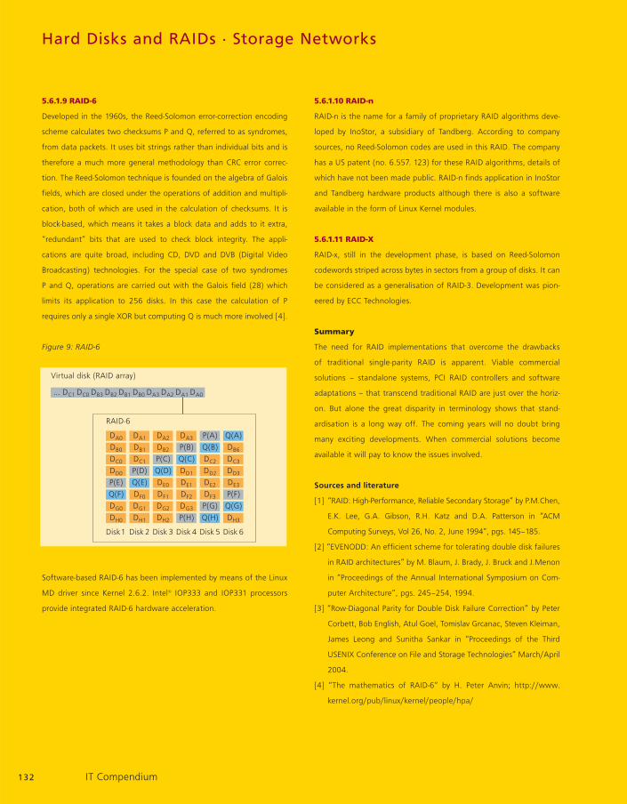
5.6.1.9 RAID-6
Developed in the 1960s, the Reed-Solomon error-correction encoding
scheme calculates two checksums P and Q, referred to as syndromes,
from data packets. It uses bit strings rather than individual bits and is
therefore a much more general methodology than CRC error correc-
tion. The Reed-Solomon technique is founded on the algebra of Galois
fields, which are closed under the operations of addition and multipli-
cation, both of which are used in the calculation of checksums. It is
block-based, which means it takes a block data and adds to it extra,
“redundant” bits that are used to check block integrity. The appli-
cations are quite broad, including CD, DVD and DVB (Digital Video
Broadcasting) technologies. For the special case of two syndromes
P and Q, operations are carried out with the Galois field (28) which
limits its application to 256 disks. In this case the calculation of P
requires only a single XOR but computing Q is much more involved [4].
Figure 9: RAID-6
Software-based RAID-6 has been implemented by means of the Linux
MD driver since Kernel 2.6.2. Intel® IOP333 and IOP331 processors
provide integrated RAID-6 hardware acceleration.
5.6.1.10 RAID-n
RAID-n is the name for a family of proprietary RAID algorithms deve-
loped by InoStor, a subsidiary of Tandberg. According to company
sources, no Reed-Solomon codes are used in this RAID. The company
has a US patent (no. 6.557. 123) for these RAID algorithms, details of
which have not been made public. RAID-n finds application in InoStor
and Tandberg hardware products although there is also a software
available in the form of Linux Kernel modules.
5.6.1.11 RAID-X
RAID-x, still in the development phase, is based on Reed-Solomon
codewords striped across bytes in sectors from a group of disks. It can
be considered as a generalisation of RAID-3. Development was pion-
eered by ECC Technologies.
Summary
The need for RAID implementations that overcome the drawbacks
of traditional single-parity RAID is apparent. Viable commercial
solutions – standalone systems, PCI RAID controllers and software
adaptations – that transcend traditional RAID are just over the horiz-
on. But alone the great disparity in terminology shows that stand-
ardisation is a long way off. The coming years will no doubt bring
many exciting developments. When commercial solutions become
available it will pay to know the issues involved.
Sources and literature
[1] “RAID: High-Performance, Reliable Secondary Storage” by P.M.Chen,
E.K. Lee, G.A. Gibson, R.H. Katz and D.A. Patterson in “ACM
Computing Surveys, Vol 26, No. 2, June 1994”, pgs. 145–185.
[2] “EVENODD: An efficient scheme for tolerating double disk failures
in RAID architectures” by M. Blaum, J. Brady, J. Bruck and J.Menon
in “Proceedings of the Annual International Symposium on Com-
puter Architecture”, pgs. 245–254, 1994.
[3] “Row-Diagonal Parity for Double Disk Failure Correction” by Peter
Corbett, Bob English, Atul Goel, Tomislav Grcanac, Steven Kleiman,
James Leong and Sunitha Sankar in “Proceedings of the Third
USENIX Conference on File and Storage Technologies” March/April
2004.
[4] “The mathematics of RAID-6“ by H. Peter Anvin; http://www.
kernel.org/pub/linux/kernel/people/hpa/
132 IT Compendium
DA0
DB0
DC0
DD0
P(E)Q(F)DG0
DH0
DA1
DB1
DC1
P(D)Q(E)DF0
DG1
DH1
DA2
DB2
P(C)Q(D)DE0
DF1
DG2
DH2
DA3
P(B)Q(C)DD1
DE1
DF2
DG3
P(H)
P(A)Q(B)DC2
DD2
DE2
DF3
P(G)Q(H)
Q(A)DB6
DC3
DD3
DE3
P(F)Q(G)DH3
… DC1 DC0 DB3 DB2 DB1 DB0 DA3 DA2 DA1 DA0
Virtual disk (RAID array)
RAID-6
Disk1 Disk 2 Disk 3 Disk 4 Disk 5 Disk 6
6. Storage networks
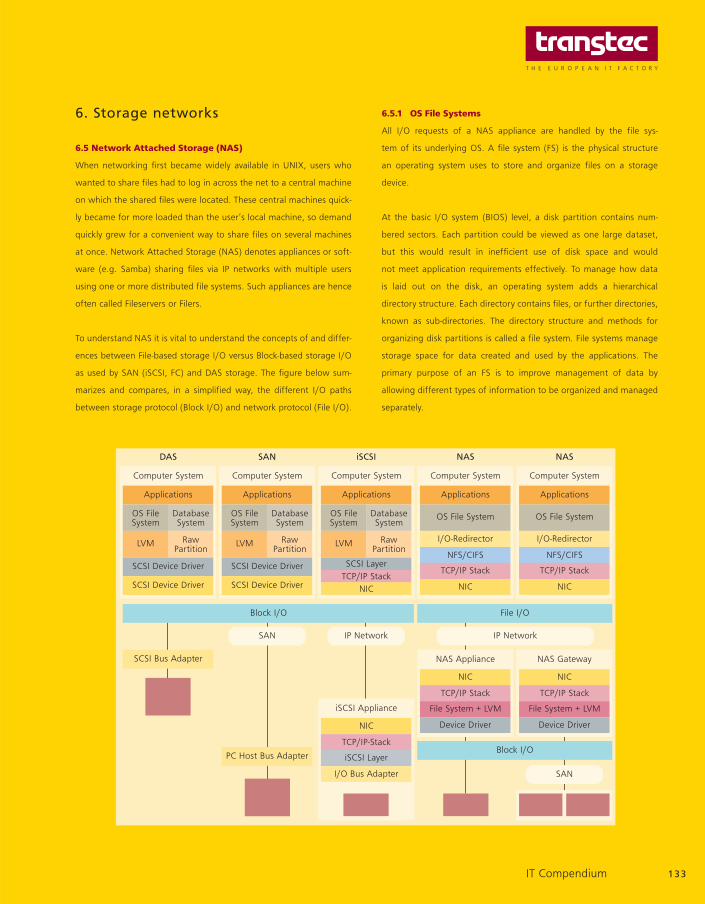
6.5 Network Attached Storage (NAS)
When networking first became widely available in UNIX, users who
wanted to share files had to log in across the net to a central machine
on which the shared files were located. These central machines quick-
ly became for more loaded than the user’s local machine, so demand
quickly grew for a convenient way to share files on several machines
at once. Network Attached Storage (NAS) denotes appliances or soft-
ware (e.g. Samba) sharing files via IP networks with multiple users
using one or more distributed file systems. Such appliances are hence
often called Fileservers or Filers.
To understand NAS it is vital to understand the concepts of and differ-
ences between File-based storage I/O versus Block-based storage I/O
as used by SAN (iSCSI, FC) and DAS storage. The figure below sum-
marizes and compares, in a simplified way, the different I/O paths
between storage protocol (Block I/O) and network protocol (File I/O).
6.5.1 OS File Systems
All I/O requests of a NAS appliance are handled by the file sys-
tem of its underlying OS. A file system (FS) is the physical structure
an operating system uses to store and organize files on a storage
device.
At the basic I/O system (BIOS) level, a disk partition contains num-
bered sectors. Each partition could be viewed as one large dataset,
but this would result in inefficient use of disk space and would
not meet application requirements effectively. To manage how data
is laid out on the disk, an operating system adds a hierarchical
directory structure. Each directory contains files, or further directories,
known as sub-directories. The directory structure and methods for
organizing disk partitions is called a file system. File systems manage
storage space for data created and used by the applications. The
primary purpose of an FS is to improve management of data by
allowing different types of information to be organized and managed
separately.
133
Applications
Computer System
DAS
SCSI Device Driver
SCSI Device Driver
OS FileSystem
DatabaseSystem
LVM RawPartition
Applications
Computer System
SAN
SCSI Device Driver
SCSI Device Driver
OS FileSystem
DatabaseSystem
LVM RawPartition
Applications
Computer System
iSCSI
SCSI LayerTCP/IP Stack
NIC
OS FileSystem
DatabaseSystem
LVM RawPartition
Applications
Computer System
NAS
OS File System
NFS/CIFS
I/O-Redirector
TCP/IP Stack
NIC
NAS Appliance
iSCSI Appliance
TCP/IP-Stack
NIC
iSCSI Layer
I/O Bus Adapter
NAS Gateway
NIC
File System + LVM
Device Driver
Applications
Computer System
NAS
OS File System
NFS/CIFS
I/O-Redirector
TCP/IP Stack
NIC
Block I/O File I/O
IP NetworkIP NetworkSAN
SAN
SCSI Bus Adapter
PC Host Bus Adapter
IT Compendium
File System + LVM
TCP/IP Stack TCP/IP Stack
Device Driver
NIC
Block I/O

Storage networks
The FS is implemented through a set of operating system commands
that allow creation, management, and deletion of files. A set of sub-
routines allows lower level access, such as open, read, write, and close
to files in the file system. The FS defines file attributes (read only, sys-
tem file, archive, and so on), and allocates names to files according to
a naming convention specific to the file system. The FS also defines
maximum size of a file and manages available free space to create
new files.
A file system does not work directly with the disk device. A file system
works with abstract logical views of the disk storage, which are crea-
ted by the volume manager function. In other words, the disk may be
virtual or real. From the file system’s point of view it does not matter.
The FS maintains a map of the data on the disk drives, including virtu-
al volumes. From this map the FS finds space which is available to store
the file. It then converts the original file I/O request to storage pro-
tocols (some number of block I/O operations). Finally, the FS creates
metadata (data describing the file) which is used for systems and
storage management purposes, and determines access rights to the
file.
High-end NAS appliances from manufacturers such as Network Appli-
ance or EMC often use UNIX derivates as OS and proprietary file
systems designed for maximum I/O efficiency and storage capacity.
More inexpensive midrange and entry-level NAS systems use standard
OS and file systems like Windows (NTFS) or Linux (ext2, ext3, Riser FS).
A disk drive may have partitions with file systems belonging to several
different operating systems. Generally an operating system will ignore
those partitions whose ID represents an unknown file system. The file
system is usually tightly integrated with the OS. However, in storage
networks it may be separated from the OS and distributed to multiple
remote platforms. This is to allow a remote file system (or part of a file
system) to be accessed as if it were part of a local file system. Later we
will see how this happens with Network File System (NFS) and
Common Internet File System (CIFS).
6.5.2 I/O Redirector
A NAS appliance allows users to access its files via logical drives and
shared group directories as if being present on the user’s local com-
puters. When a user or application issues a file I/O request to access
such a file located on a remote NAS system, the local file system can-
not manage the I/O request as it has no information about the sto-
rage device where the file is stored. To overcome this the I/O must be
redirected via the network to the NAS appliance.
An I/O redirector is located in the client I/O path in front of the client’s
local file system. It presents a common view of the client’s local file
system, and, transparently, the remote NAS appliance’s file system.
The I/O redirector has no knowledge of the metadata relating to
either of the files systems. An I/O request to a file that is located in the
remote NAS appliance is intercepted by the redirector on the client
computer. The redirector then constructs a data packet containing all
of the information about the request, and sends it via the client’s
Network Interface Card and Ethernet LAN/WAN to the NAS system
where the file is located. Since the client system has no awareness
of the storage device characteristics on which the data is stored, all
redirected I/Os must be done at the file (byte range) level. This is
called a “File I/O”.
Since the NIC uses a network protocol, such as the TCP/IP stack or
more seldomly UDP/IP, the I/O operation must be transferred using a
network protocol. Now one of the network file protocols such as NFS
(Unix/Linux), SMB/CIFS (Windows), NCP (NetWare) or AppleTalk
(MacOS) comes into play as a kind of network device driver. In effect,
the network file protocol lies on top of the lower level communications
protocol stack, such as TCP/IP. It is the TCP/IP protocol that carries the
redirected I/O through the NIC onto the network.
When the NAS appliance receives the redirected I/O, the requests are
“unbundled” from their TCP/IP network protocols in the receiving NIC
and sent to the NAS appliance’s network file protocol. It controls
tracking information in order to be able to direct the response back to
the correct client’s network address. Now the request is submitted to
the NAS appliance’s operating system, which manages the scheduling
of the I/O, and security processes to the local disk. From then on the
I/O is handled more or less like a local I/O and issues read/write com-
mands on the NAS storage devices blocks. Finally, the returning I/O
basically follows the reverse route as described above.
134 IT Compendium

6.5.3 Network File System (NFS)
The Network File System (NFS) was the first commercially successful
and widely available remote file protocol. Originally designed and
implemented by Sun Microsystems in 1985, the protocol specification
was placed in the public domain. From the beginning NFS was
designed for remote file access and sharing via networks with various
types of machines, operating systems, network architectures and
transport protocols. Today it is still further extended and standardized
under the supervision of the Internet Engineering Task Force (IETF).
NFS Version 2 was eventually codified as an official TCP/IP standard
when RFC 1094 was published in 1989. NFS Version 3 was subse-
quently developed and published in 1995 as RFC 1813. It is similar to
version 2 but makes a few changes and adds some new capabilities.
These include support for larger files, larger file transfers, better sup-
port for setting file attributes, and several new file access and manip-
ulation procedures. NFS v2/3 are still the most widespread versions,
while NFS v4 as newest standard was published in 2000 as RFC 3010
and was virtually a rewrite of NFS including numerous changes.
NFS follows the classical server/client model and consists of a server
program and a client program. The server program allows adminis-
trators to set up local volumes, directories or files as shared resources,
making them available for access by other machines via a process
called exporting. NFS clients access shared file systems by mounting
them from an NFS server machine. NFS uses an architecture that
includes three main components that define its operation. The Mount
protocol is used to mount resources and allows the server to grant
remote access privileges to a restricted set of clients via export control.
Then, the External Data Representation (XDR) standard defines how
data is represented in exchanges between clients and servers. The
Remote Procedure Call (RPC) protocol is used as a method of calling
procedures on remote machines.
The NFS protocol was designed to be stateless. The server does not
need to maintain any information about which clients it is serving or
about the files that they currently have open. Because there is no state
to maintain or recover, NFS is very robust and can continue to operate
even during periods of client or server failures. But there are draw-
backs to the stateless protocol related to performance and when to
free file space.
NFS v2 has 16 different RPCs and originally operated entirely via the
unreliable UDP datagram protocol. While UDP is faster than TCP, it
doesn't provide any error checking. NFS relied on the built-in retry
logic of the RPCs to make sure that requests and replies arrive at their
destinations. The client can specify block sizes, number of retry
attempts, and time to wait values when it mounts the server file sys-
tems. Before a client issues an RPC request to the server it checks to
see if the desired data is already cached from an earlier request. If the
data is newer than the cache attribute timeout value then the data is
used, otherwise it sends a request to the server to compare the mod-
ification time of it’s cached file with that of the server’s file. If the serv-
er’s file is newer a request to resend the data is issued.
NFS v3 offered some significant enhancements over earlier versions.
NFS can now run on top of the TCP protocol. Additionally it now sup-
ports safe asynchronous writes, finer access control, and larger file
transfer sizes, with less overhead. Since NFS is stateless one has to
make sure that the server has really performed the write request to a
stable storage area before acknowledging it to the client. Version 3
allows unsafe asynchronous writes to be committed to stable storage
reliably. Also the maximum transfer size has been increased from 8 kB
to 4 GB, where the machines negotiate the transfer size, up to 64 KB,
the maximum allowed for both UDP and TCP. The protocol, either TCP
or UDP, is also negotiated between the machines, defaulting to TCP if
both ends support it. The new protocol now allows 64 bits file offsets,
up from the former 32 bits limit, supporting arbitrarily large file sizes.
The new version is more efficient, e.g. it returns the file attributes
after each call, eliminating the need to issue a separate request for
this information.
135IT Compendium

Local Area Networks – LANs
7. Magnetic Tape Storage
8. Optical Storage
9. Working Memories
10. Communication
11. Standards
12. The OSI Reference Model
13. Transmission Methods and
Techniques
14. Personal Area Networks – PANs
Chapters 7–14 can be found online at
www.transtec.co.uk
www.ttec.nl
www.ttec.be.
15. Local Area Networks – LANs
15.5 Ethernet standards
There is a variety of implementations from Ethernet, which mostly dif-
ferentiate in terms of speed, transmission mode, maximum segment
length, as well as types of connectors. Thus the nomenclature of the
standard 10BASE-5 according to IEEE802.3, refers to an Ethernet with
10 Mbit/sec. baseband transmission with a maximum segment length
of 500 m. The most important standards that are already in practice
and will possibly be put into practice are described in more detail
below.
Ethernet type Cable type Connector Length (m)
10Base-5 Yellow cable AUI 500
10Base-2 Coax BNC 185
10Base-T CAT3 RJ-45 100
10Base-FL MM-fibre ST 2.000
100Base-TX CAT5 RJ-45 100
100Base-FX MM-fibre SC/MT-RJ 2.000
1000Base-T CAT5 RJ-45 100
1000Base-SX MM-fibre LC/SC/MT-RJ 270/550
1000Base-LX MM/SM-fibre LC/SC/MT-RJ 550/500
15.5.2 10BASE-5
The standard 10BASE-5 according to IEEE802.3, refers to an Ethernet
with 10 Mbit/sec baseband transmission with a maximum transmission
section of 500 m. 10BASE-5 is also known as Thick Net, since it uses a
thick RG8 50 Ohm coaxial cable as a transmission medium. Thick Net
physically uses the bus topology and the 5-4-3 repeater rule has to
be observed. This means that a Thick Net may have a maximum of 5
segments with a maximum segment length of 500 m via 4 repeaters
that are connected together. This results in a maximum of 3 inter
Repeater Links (IRL). A maximum of 100 stations may be connected
per segment, whereby the AUI (Attachment Unit Interface) connector
is used. The maximum length of the AUI cable is 50 m. The 10BASE-5
standard was used extensively in the past, but is not included in new
installations.
136 IT Compendium

15.5.2 10BASE-2
The standard 10BASE-2 according to IEEE802.3a, refers to an Ethernet
with 10 Mbit/sec baseband transmission with a maximum segment
length of 185 m. 10BASE-2 is also known as Thin Net or Cheaper Net,
since it uses a thin RG58 50 Ohm coaxial cable as a transmission medi-
um. Thin Net physically uses the bus topology, whereby the minimum
segment length between two stations is 0.5 m and a maximum of 4
repeaters may be switched between two stations. A maximum of 30
stations may be connected per segment and the BNC T adapter is used
as the connector. The 10BASE-2 standard has been used extensively in
recent times, but it is not included in new installations.
15.5.3 10BASE-T
The standard 10BASE-2 according to IEEE802.3i, refers to an Ethernet
with 10 Mbit/sec baseband transmission with a maximum segment
length of 100 m with copper-based cabling. Copper twisted pair cables
of various standards are used as the transmission medium along with
RJ-45 connectors. The various cable standards will be discussed in a
later chapter. The 10BASE-T physically uses the star topology, i.e. one
active component is used to concentrate the stations into a star shape,
the concentrator for this is also used as the amplifier. The 10BASE-T
standard has been used extensively for just a short while and has a
wide installed basis, but it is not included in new installations.
15.5.4 10BASE-FL
The standard 10BASE-FL according to IEEE802.23j refers to an
Ethernet with 10 Mbit/sec baseband transmission with a maximum
segment length of 2,000 m with fibre-optic-based cabling. Fibre-optic
duplex cables are used as the transmission medium, which often use
ST connectors. The various cable standards will be discussed in a later
chapter (15.9). The standard is an expansion to FOIRL (Fiber Optic
Inter Repeater Link) and defines the connection between concentra-
tors, as well as between stations and concentrators. The 10BASE-FL
standard has been used extensively in recent times and has a wide
installed basis, but it is not included in new installations.
15.5.5 100BASE-TX
The standard 100BASE-TX according to IEEE802.3u, refers to an
Ethernet with 100 Mbit/sec baseband transmission with a maximum
segment length of 100 m with copper-based cabling. Copper twisted
pair cables of various standards are used as the transmission medium
along with RJ-45 connectors. The various cable standards will be
discussed in a later chapter (15.9). The 100BASE-TX physically uses the
star topology, i.e. one active component is used to concentrate the
stations into a star shape, the concentrator for this is also used as the
amplifier. The 100BASE-TX has a wide installed basis and is used very
often in new installations.
15.5.6 100BASE-FX
The standard 100BASE-FX according to IEEE802.3u, refers to an
Ethernet with 100 Mbit/sec. baseband transmission with a maximum
segment length of 400 m between stations and concentrators and
2,000 m between concentrators. Fibre-optic duplex cables are used as
the transmission medium, which often use ST, SC, MT-RJ, LC or VF-45
connectors. The various cable standards will be discussed in a later
chapter (15.9). 100BASE-FX is used with the FDDI (Fibre Distributed
Data Interface), which works according to the time token process. The
100BASE-FX has an installed basis and is also used in new installations
in fibre-optic cable environments.
15.5.7 1000BASE-T
The standard 1000BASE-T according to IEEE802.3ab refers to an
Ethernet with 1000 Mbit/sec. baseband transmission with a maximum
segment length of 100 m in the terminal section. Copper twisted pair
cables of various standards are used as the transmission medium
along with RJ-45 connectors. The various cable standards will be dis-
cussed in a later chapter (15.9). The 1000BASE-TX physically uses the
star topology, i.e. one active component is used to concentrate the
stations into a star shape, the concentrator for this is also used as the
amplifier. The 1000BASE-T standard is an addition to the 100BASE-T2
standard and 100BASE-T4 standard which specify characteristics for
transmission via category 3 copper cables and in this case use more
than two pairs of wires. In order to reach 1000 Mbit/sec, 250 Mbit/s
are transmitted via ever pair of wires. This standard is becoming more
and more widely accepted and is used in new installations.
137IT Compendium

Local Area Networks – LANs
15.5.8 1000BASE-SX
The 1000BASE-SX standard according to IEEE802.z refers to a Gigabit
Ethernet with 1000 Mbit/sec. baseband transmission via short wave-
length. This means that it is processed by means of a wavelength of
850 nm and, depending on the fibre-optic cable, can bridge a distance
of 275 m maximum for 62.5/125 micron multimode fibres and 550 m
maximum for 50/125 micron multimode fibres. This standard uses a
point-to-point connection with CSMA/CD. SC connectors are com-
monly used, but MT-RJ and VF-45 connectors may also be used.
Besides the copper match, this standard is widely accepted and used
in new fibre optic cable installations.
15.5.9 1000BASE-LX
The 1000BASE-LX standard according to IEEE802.z refers to a Gigabit
Ethernet with 1000 Mbit/sec. baseband transmission via long wave-
length. This means that it is processed by means of a wavelength of
1300 nm and, depending on the fibre-optic cable, can bridge a dis-
tance of 550 m maximum for 62,5/125 or 50/125 micron multimode
fibres and 5000 m maximum for 9/125 micron single-mode fibres.
Larger distances can be bridged, but these are usually a manufactur-
er-specific solutions that are only compatible to each other. This stand-
ard uses a point-to-point connection and without the used of CSMA/
CD. SC connectors are generally used. In addition to the 1000BASE-
SC, the 1000BASE-LX is a solution for structured cabling in the LWL pri-
mary sector and has gained acceptance in this area.
15.5.10 10 Gigabit Ethernet
2002 witnessed the rollout of the IEEE 802.3ae standard also referred
to as 19 Gigabit Ethernet, 10 GbE in short. This Ethernet standard is the
first to be based exclusively on the use of optical connectivity media.
These include the following specified variants: 10GBaseSR, 10GBaseLR,
10GBaseER, 10GBaseLX4, 10GBaseSW, 10GBaseLW and 10GBaseEW.
The letters S, L and E indicate the wavelength used. S (850 nm wave-
length), L (1,310 nm wavelength and E (1,550 nm wave length).
10GBase-X 10GBase-R 10GBase-W
LAN LAN WAN
8B/10B 64B/66B SONET
Short 850 nm 10GBase-SR 10GBase-SW
Long 1.310 nm 10GBase-LX4 10GBase-LR 10GBase-LW
10GBase-LW4
Extra Long 10GBase-ER 10GBase-EW
1.550 nm
The wavelengths in combination with the glass-fibre cable types used
also provide information on the possible data transfer distances.
10 GbE also supports Sonet/SDH. There are two different physical
Wavelength Fibre-glass Bandwidth Distance
850 nm 50 µm 500 MHz 65 m
1310 nm WWDM 62,5 µm 160 MHz 300 m
1310 nm WWDM 9 µm 10.000 m
1310 nm 9 µm 10.000 m
1550 nm 9 µm 40.000 m
10 GbE interfaces available: one for the LAN sector with 10 Gbit/sec.
and one for Wide Area Networks (WAN) with 9.584640 Gbit/sec.,
which corresponds to the Sonet OC-192c/SDH level VC-4-64c.
138 IT Compendium
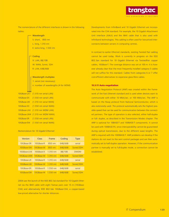
The nomenclature of the different interfaces is shown in the following
tables:
Wavelength
S: short, 850 nm
L: long, 1.310 nm
E: extra long, 1.550 nm
Coding
X: LAN, 8B/10B
W: WAN, Sonet, SDH
R: LAN, 64B/66B
Wavelength multiplex
1: serial (not necessary)
n: number of wavelengths (4 for WDM)
10GBase-LX1 (1.310 nm serial LAN)
10GBase-EX (1.550 nm serial LAN)
10GBase-LW (1.310 nm serial WAN)
10GBase-EX (1.550 nm serial WAN)
10GBase-LX4 (1.310 nm WDM LAN)
10GBase-LW4 (1.310 nm WDM WAN)
10GBase-ER (1.550 nm serial LAN)
10GBase-EW (1.550 nm serial WAN)
Nomenclature for 10 Gigabit Ethernet
Version Class Frame Coding Type
10GBase-SR 10GBase-R 850 nm 64B/66B serial
10GBase-SW 10GBase-W 850 nm 64B/66B Sonet/SDH
10GBase-LX4 10GBase-X 1.310 nm 8B/10B DWDM
10GBase-LW4 10GBase-W 1.310 nm 64B/66B Sonet/SDH
10GBase-LR 10GBase-R 1.310 nm 64B/66B serial
10GBase-LW 10GBase-W 1.310 nm 64B/66B Sonet/SDH
10GBase-ER 10GBase-R 1.550 nm 64B/66B serial
10GBase-EW 10GBase-W 1.550 nm 64B/66B Sonet/SDH
2004 saw the launch of the IEEE 802.3ai standard for 10 Gigabit Ether-
net via the IB4X cable with eight Twinax pairs over 15 m (10GBase-
CX4) and alternatively IEEE 802.3ak 10GBase-CX4, a copper-based
low-priced alternative for shorter distances.
Developments from InfiniBand and 10 Gigabit Ethernet are incorpo-
rated into the CX4 standard. For example, the 10 Gigabit Attachment
Unit Interface (XAUI) and the IB4X cable that is also used with
Infiniband technologies. This cabling is often used for low-priced inter-
connects between servers in computing centres.
In contrast to earlier Ethernet standards, existing Twisted Pair cabling
cannot be used today. Work is currently in progress on the IEEE
802.3an standard for 10 Gigabit Ethernet via TwistedPair copper
cables, 10GBase-T. The coverage distance was set at 100 m. It is how-
ever already clear that the most frequently installed category 5 cables
will not suffice for this standard. Cables from categories 6 or 7 offer
cost-efficient alternatives to expensive glass-fibre cables.
15.5.11 Auto negotiation
The Auto Negotiation Protocol (ANP) was created within the frame-
work of the Fast Ethernet standard and is used when devices want to
communicate with either 10 Mbit/sec. or 100 Mbit/sec. The ANP is
based on the Nway protocol from National Semiconductor, which is
also extensively used. The protocol automatically sets the highest pos-
sible speed that can be used for communication between the connect-
ed partners. The type of operation is also selected, either half-duplex
or full- duplex, as described in the Transmission Modes chapter. The
ANP is optional for 10BASE-T and 100BASE-T components. It cannot
be used with 100BASE-FX, since interoperability cannot be guaranteed
during optical transmission, due to the different wave lengths. The
ANP is required with the 1000BASE-T. ANP problems can develop if the
stations do not react to the sent control packages and are then auto-
matically set to half-duplex operation. However, if the communication
partner is manually set to full-duplex mode, a connection cannot be
established.
139IT Compendium
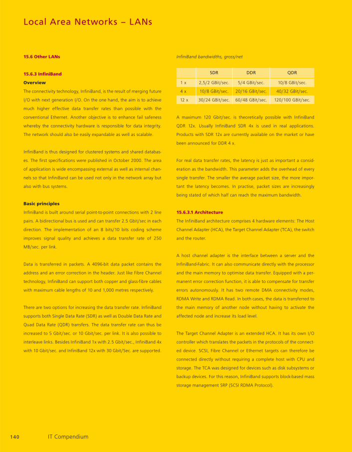
Local Area Networks – LANs
15.6 Other LANs
15.6.3 InfiniBand
Overview
The connectivity technology, InfiniBand, is the result of merging future
I/O with next generation I/O. On the one hand, the aim is to achieve
much higher effective data transfer rates than possible with the
conventional Ethernet. Another objective is to enhance fail safeness
whereby the connectivity hardware is responsible for data integrity.
The network should also be easily expandable as well as scalable.
InfiniBand is thus designed for clustered systems and shared databas-
es. The first specifications were published in October 2000. The area
of application is wide encompassing external as well as internal chan-
nels so that InfiniBand can be used not only in the network array but
also with bus systems.
Basic principles
InfiniBand is built around serial point-to-point connections with 2 line
pairs. A bidirectional bus is used and can transfer 2.5 Gbit/sec in each
direction. The implementation of an 8 bits/10 bits coding scheme
improves signal quality and achieves a data transfer rate of 250
MB/sec. per link.
Data is transferred in packets. A 4096-bit data packet contains the
address and an error correction in the header. Just like Fibre Channel
technology, InfiniBand can support both copper and glass-fibre cables
with maximum cable lengths of 10 and 1,000 metres respectively.
There are two options for increasing the data transfer rate. InfiniBand
supports both Single Data Rate (SDR) as well as Double Data Rate and
Quad Data Rate (QDR) transfers. The data transfer rate can thus be
increased to 5 Gbit/sec. or 10 Gbit/sec. per link. It is also possible to
interleave links. Besides InfiniBand 1x with 2.5 Gbit/sec., InfiniBand 4x
with 10 Gbit/sec. and InfiniBand 12x with 30 Gbit/Sec. are supported.
InfiniBand bandwidths, gross/net
SDR DDR QDR
1 x 2,5/2 GBit/sec. 5/4 GBit/sec. 10/8 GBit/sec.
4 x 10/8 GBit/sec. 20/16 GBit/sec. 40/32 GBit/sec.
12 x 30/24 GBit/sec. 60/48 GBit/sec. 120/100 GBit/sec.
A maximum 120 Gbit/sec. is theoretically possible with InfiniBand
QDR 12x. Usually InfiniBand SDR 4x is used in real applications.
Products with SDR 12x are currently available on the market or have
been announced for DDR 4 x.
For real data transfer rates, the latency is just as important a consid-
eration as the bandwidth. This parameter adds the overhead of every
single transfer. The smaller the average packet size, the more impor-
tant the latency becomes. In practise, packet sizes are increasingly
being stated of which half can reach the maximum bandwidth.
15.6.3.1 Architecture
The InfiniBand architecture comprises 4 hardware elements: The Host
Channel Adapter (HCA), the Target Channel Adapter (TCA), the switch
and the router.
A host channel adapter is the interface between a server and the
InfiniBand-Fabric. It can also communicate directly with the processor
and the main memory to optimise data transfer. Equipped with a per-
manent error correction function, it is able to compensate for transfer
errors autonomously. It has two remote DMA connectivity modes,
RDMA Write and RDMA Read. In both cases, the data is transferred to
the main memory of another node without having to activate the
affected node and increase its load level.
The Target Channel Adapter is an extended HCA. It has its own I/O
controller which translates the packets in the protocols of the connect-
ed device. SCSI, Fibre Channel or Ethernet targets can therefore be
connected directly without requiring a complete host with CPU and
storage. The TCA was designed for devices such as disk subsystems or
backup devices. For this reason, InfiniBand supports block-based mass
storage management SRP (SCSI RDMA Protocol).
140 IT Compendium

In the InfiniBand network, the switch controls the point-to-point con-
nections in compliance with the requirements of the connected HCAs
and TCAs. It specifies the selected target over the local route header
of the single data packets and relays it to the relevant components.
An InfiniBand router also transports data packets from the local net-
work to other subnetworks if necessary. To do this, the router analy-
ses the global route header and translates this into a network layer
address in compliance with IPv6. It also translates the headers of
received packets and configures the local address header accordingly.
Single links are always interleaved together within an InfiniBand net-
work. This is why an HCA with IB 4 x with 4 aggregated links can be
connected to multiple targets at the same time. This ensures redun-
dancy on the hardware level. Connectivity reliability can be guaran-
teed using a reliable connection with which the hardware is respons-
ible for data integrity.
15.6.3.2 Framework conditions
InfiniBand Adapters are available with PCI-X, PCI-Express and HTX
Interface. The use of PCI-X limits the function of an InfiniBand 4 x
Interface and releases just 80 % of the maximum bandwidth.
Driver support is comprehensive. Windows®, Linux and Mac OS are all
supported. Since the 2.6.11 kernel, InfiniBand is a native feature in
Linux.
MVAPICH from the Ohio State University OSU as well as MPICH-VMI
from the National Center for Supercomputing Applications can be
used as the MPI (Message Passing Interface).
InfiniPath
The InfiniBand Adapter from Pathscale is a special IT feature. These
cards marketed under the brand name InfiniPath eliminate the need
for conventional PCI buses and connects the server to the network via
the hyper transport tunnel. This is possible as in the typical Dual and
Quad OpteronTM architecture at least one HyperTransport connection
of an AMD Opteron remains free. The packets can be exchanged at far
lower latency rates via this HTX (HyperTransport Exchange) interface.
In this concept, the processor manages the protocols.
16. Metropolitan Area Networks –
MANs
17. Wide Area Networks – WANs
18. LAN Core Solutions
19. Input Devices
20. Data Communication
21. Terminals
22. Output Devices
23. Multimedia
24. Uninterruptible Power Supplies
Chapters 16–24 can be found online at
www.transtec.co.uk
www.ttec.nl
www.ttec.be.
141IT Compendium