Social Media & Women's Health, Merrillville, IN May 12, 2011

THE TOWN OF MERRILLVILLE, INDIANA
STORMWATER TECHNICAL STANDARDS MANUAL
MANUAL 2
May 2010 Edition
EXHIBIT B
WITNESS WHEREOF, the Town of Merrillville, Indiana has caused these documents to be signed in its name and behalf by the President of its Town Council, President of its Planning Commission and attest by its Clerk-Treasurer, and to evidence its acceptance of these documents hereby created. TOWN OF MERRILLVILLE, INDIANA By:_________________________________ Date:__________ Richard Hardaway, President, Town Council
By:_________________________________ Date:__________ Shawn Pettit, President, Planning Commission Attest: ____________________________________ Date:__________ Eugene M. Guernsey, Clerk Treasurer

Table of Contents♦ Page i
TABLE OF CONTENTS
Chapter Title
1 INTRODUCTION 2 METHODOLOGY FOR DETERMINATION OF RUNOFF RATES 3 METHODOLOGY FOR DETERMINATION OF DETENTION STORAGE VOLUMES 4 STORM SEWER DESIGN STANDARDS AND SPECIFICATIONS 5 OPEN CHANNEL DESIGN STANDARDS AND SPECIFICATIONS 6 STORMWATER DETENTION DESIGN STANDARDS 7 EROSION CONTROL PRACTICES AND CONSTRUCTION PHASE BMPS 8 POST-CONSTRUCTION STORMWATER QUALITY BMPS
9 METHODOLOGY FOR DETERMINATION OF REQUIRED SIZING OF BMPS APPENDIX A : ABBREVIATIONS AND DEFINITIONS APPENDIX B : STANDARD FORMS APPENDIX C : CONSTRUCTION BMP FACT SHEETS APPENDIX D : POST-CONSTRUCTION BMP FACT SHEETS

Chapter 1 – Page 1
INTRODUCTION This document, the Town of Merrillville Stormwater Technical Standards Manual, contains the necessary technical standards for administering the requirements of 327 IAC 15-13 and the Town of Merrillville Stormwater Management ordinance. This document should be considered as a companion document to the Ordinance. Whereas the Ordinance contains the majority of the regulatory authority and general requirements of comprehensive stormwater management, this document contains the necessary means and methods for achieving compliance with the Ordinance. It is not intended as a regulatory document, but rather guidance to assist plan reviewers, developers, and designers. In case there are conflicts between the requirements contained in this document and the ordinance, the requirements of the Ordinance shall prevail. In addition to the stormwater standards provided in this document, Town of Merrillville may have adopted, or may adopt in the future, separate other technical standards regarding various aspects of stormwater conveyance systems that for various reasons may not have been incorporated in this Technical Standards document. In case there are conflicts between the requirements contained in this document and the noted standards, the most restrictive requirements shall prevail. This document contains formulas and methodologies for the review and design of both stormwater quantity and stormwater quality facilities. Chapters 2 through 6 contain stormwater conveyance and detention calculations and requirements. Chapter 7 contains information on erosion control requirements and other pollution prevention measures for active construction sites. Chapters 8 through 9 cover calculations required to properly size and design stormwater quality features that will treat runoff long-term following construction completion. A comprehensive glossary of terms is provided in Appendix A. Appendix B contains several useful and necessary standard forms. Best Management Practices (BMPs) for erosion control measures during the construction phase are contained in Appendix C. Appendix D contains BMPs for post-construction erosion and sediment control measures. It is the intent of the Town of Merrillville Town Engineer that material presented in Appendices C and D will be revised or eliminated once the Indiana Stormwater Quality Manual is published in its final form by the Indiana Department of Natural Resources (IDNR) to provide consistency.
TABLE OF CONTENTS
Chapter One

Chapter 2 – Page 1
METHODOLOGY FOR DETERMINATION OF
RUNOFF RATES Runoff rates shall be computed for the area of the parcel under development plus the area of the watershed flowing into the parcel under development. The rate of runoff which is generated as the result of a given rainfall intensity may be calculated as follows:
A. Development Sites Less than or Equal to 5 Acres in Size, With a Contributing Drainage Area Less than or Equal to 50 Acres and No Depressional Storage
The Rational Method may be used. A computer model, such as TR-55 (NRCS), TR-20 (NRCS), HEC-HMS (COE), and HEC-1 (COE), that can generate hydrographs based on the NRCS TR-55 time of concentration and curve number calculation methodologies may also be used along with a 24-hour duration NRCS Type 2 storm. In the Rational Method, the peak rate of runoff, Q, in cubic feet per second (cfs) is computed as:
CIAQ =
Where: C = Runoff coefficient, representing the characteristics of the
drainage area and defined as the ratio of runoff to rainfall.
I = Average intensity of rainfall in inches per hour for a duration equal to the time of concentration (tc) for a selected rainfall frequency.
A = Tributary drainage area in acres.
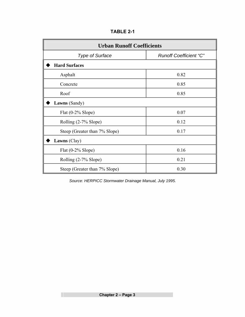
Values for the runoff coefficient "C" are provided in Tables 2-1 and 2-2, which show values for different types of surfaces and local soil characteristics. The composite "C" value used for a given drainage area with various surface types shall be the weighted average value for the total area calculated from a breakdown of individual areas having different surface types. Table 2-3 provides runoff coefficients and inlet times for different land use classifications.
Chapter Two

Chapter 2 – Page 2
Rainfall intensity shall be determined from the rainfall frequency data shown in Table 2-4.
In general, the time of concentration (tc) methodology to be used for all stormwater management projects within Town of Merrillville shall be as outlined in the U.S. Department of Agriculture (USDA) - NRCS TR-55 Manual. In urban or developed areas, the methodology to be used shall be the sum of the inlet time and flow time in the stormwater facility from the most remote part of the drainage area to the point under consideration. The flow time in the storm sewers may be estimated by the distance in feet divided by velocity of flow in feet per second. The velocity shall be determined by the Manning's Equation (see Chapter 4). Inlet time is the combined time required for the runoff to reach the inlet of the storm sewer. It includes overland flow time and flow time through established surface drainage channels such as swales, ditches, and sheet flow across such areas as lawns, fields, and other graded surfaces.
Chapter 2 – Page 3
TABLE 2-1
Urban Runoff Coefficients
Type of Surface
Runoff Coefficient “C”
Hard Surfaces
Asphalt
0.82
Concrete
0.85
Roof
0.85
Lawns (Sandy)
Flat (0-2% Slope)
0.07
Rolling (2-7% Slope)
0.12
Steep (Greater than 7% Slope)
0.17
Lawns (Clay)
Flat (0-2% Slope)
0.16
Rolling (2-7% Slope)
0.21
Steep (Greater than 7% Slope)
0.30
Source: HERPICC Stormwater Drainage Manual, July 1995.

Chapter 2 – Page 4
TABLE 2-2
Rural Runoff Coefficients
Type of Surface
Runoff Coefficient “C”
Woodland (Sandy)
Flat (0-5% Slope)
0.10
Rolling (5-10% Slope)
0.25
Steep (Greater than 10% Slope)
0.30
Woodland (Clay)
Flat (0-5% Slope)
0.30
Rolling (5-10% Slope)
0.35
Steep (Greater than 10% Slope)
0.50
Pasture (Sandy)
Flat (0-5% Slope)
0.10
Rolling (5-10% Slope)
0.16
Steep (Greater than 10% Slope)
0.22
Pasture (Clay)
Flat (0-5% Slope)
0.30
Rolling (5-10% Slope)
0.36
Steep (Greater than 10% Slope)
0.42
Cultivated (Sandy)
Flat (0-5% Slope)
0.30
Rolling (5-10% Slope)
0.40
Steep (Greater than 10% Slope)
0.52
Cultivated (Clay)
Flat (0-5% Slope)
0.50
Rolling (5-10% Slope)
0.60
Steep (Greater than 10% Slope)
0.72
Source: HERPICC Stormwater Drainage Manual, July 1995.

Chapter 2 – Page 5
TABLE 2-3
Runoff Coefficients “C”
by Land Use and Typical Inlet Times
Runoff Coefficients
Land Use
Flat (1)
Rolling
(2)
Steep
(3)
Inlet Times (Minutes)
(4)
Commercial (CBD)
0.75
0.83
0.91
5
Commercial (Neighborhood)
0.54
0.60
0.66
Industrial
0.63
0.70
0.77
Garden Apartments
0.54
0.60
0.66
Churches
0.54
0.60
0.66
5-10
Schools
0.31
0.35
0.39
Semi Detached Residential
0.45
0.50
0.55
Detached Residential
0.40
0.45
0.50
Quarter Acre Lots
0.36
0.40
0.44
Half Acre Lots
0.31
0.35
0.39
10-15
Parkland
0.18
0.20
0.22
To be
Computed
Source: HERPICC Stormwater Drainage Manual, July 1995.
(1) Flat terrain involves slopes of 0-2%. (2) Rolling terrain involves slopes of 2-7%. (3) Steep terrain involves slopes greater than 7%.
(4) Interpolation, extrapolation and adjustment for local conditions shall be based on engineering experience and judgment.
Chapter 2 – Page 6
B. Development Sites Greater Than 5 Acres in Size or Contributing Drainage Area Greater than 50 Acres or With Significant Depressional Storage
The runoff rate for these development sites and contributing drainage areas shall be determined by a computer model that can generate hydrographs based on the NRCS TR-55 time of concentration and curve number calculation methodologies and the 24-hour NRCS Type 2 Rainfall Distribution. 24-hour Rainfall depth for various frequencies shall be taken from Table 2-5. The NRCS Type 2 distribution ordinates are found in Table 2-6. Examples of computer models that can generate such hydrographs include TR-55 (NRCS), TR-20 (NRCS), HEC-HMS (COE), and HEC-1 (COE). These programs may be downloaded free of charge from the associated agencies’ web sites. Other models may be acceptable and should be accepted by the Town of Merrillville Town Engineer prior to their utilization.

Chapter 2 – Page 7
TABLE 2-4 Rainfall Intensities for Various Return Periods and Storm Durations
Intensity (Inches/Hour)
Return Period (Years)
Duration
2
5
10
25
50
100
5 Min. 5.04 8.24 7.08 8.16 9.00 9.84
10 Min. 3.84 4.74 5.46 6.24 6.90 7.50
15 Min. 3.20 3.96 4.52 5.16 5.72 6.20
20 Min. 2.85 3.51 4.02 4.59 5.10 5.55
30 Min. 2.22 2.74 3.12 3.58 3.96 4.32
40 Min. 1.85 2.28 2.61 2.99 3.30 3.60
50 Min. 1.60 1.97 2.24 2.57 2.83 3.10
1 Hr. 1.40 1.73 1.97 2.25 2.49 2.72
1.5 Hrs. 1.13 1.39 1.59 1.82 2.02 2.20
2 Hrs. 0.86 1.06 1.21 1.38 1.53 1.67
3 Hrs. 0.61 0.76 0.87 0.99 1.10 1.20
4 Hrs. 0.52 0.64 0.73 0.83 0.92 1.00
5 Hrs. 0.43 0.53 0.61 0.70 0.77 0.84
6 Hrs. 0.37 0.46 0.52 0.60 0.66 0.72
7 Hrs. 0.33 0.41 0.47 0.53 0.59 0.64
8 Hrs. 0.29 0.36 0.42 0.47 0.53 0.57
9 Hrs. 0.27 0.33 0.38 0.43 0.48 0.52
10 Hrs. 0.25 0.31 0.35 0.40 0.44 0.48
12 Hrs. 0.22 0.27 0.30 0.35 0.38 0.42
14 Hrs. 0.19 0.24 0.27 0.31 0.34 0.37
16 Hrs. 0.17 0.21 0.24 0.28 0.31 0.34
18 Hrs. 0.16 0.19 0.22 0.25 0.28 0.31
20 Hrs. 0.14 0.18 0.20 0.23 0.26 0.28
24 Hrs. 0.13 0.15 0.18 0.20 0.22 0.24

Chapter 2 – Page 8
TABLE 2-5
Rainfall Depths for Various Return Periods Depth (Inches)
Return Period (Years)
Duration
2
5
10
25
50
100
24 Hrs. 3.00 3.70 4.23 4.83 5.35 5.83
TABLE 2-6
NRCS Type II Rainfall Distribution Ordinates
Cumulative Percent of Storm Time
Cumulative Percent of Storm Depth
0 0 5 1 10 3 15 4 20 6 25 8 30 10 35 13 40 17 45 22 50 64 55 78 60 84 65 87 70 90 75 92 80 94 85 96 90 98 95 99 100 100

Chapter 2 – Page 9
C. Development Sites with Drainage Areas Greater than or Equal to One Square Mile
For the design of any major drainage system, as defined in Appendix A, the discharge must be obtained from, or be accepted by, the IDNR. Other portions of the site must use the discharge methodology in the applicable section of this Article.

Chapter 3 – Page 1
METHODOLOGY FOR DETERMINATION OF DETENTION STORAGE VOLUMES
A. Development Sites Less than or Equal to 5 Acres in Size, With a Contributing Drainage Area Less than or Equal to 50 Acres and No Depressional Storage
The required volume of stormwater storage may be calculated using the Rational Method and based on the runoff from a 100-year return period storm. A computer model, such as TR-55 (NRCS), TR-20 (NRCS), HEC-HMS (COE), and HEC-1 (COE), that can generate hydrographs based on the NRCS TR-55 time of concentration and curve number calculation methodologies may also be used along with a 24-hour duration NRCS Type 2 storm.
The following 8-step procedure, based on the Rational Method, may be used to determine the required volume of storage
Step Procedure
1. Determine total drainage area in acres "A". 2. Determine the parcel area tributary to each outlet and determine the post-
development 100-year release runoff rate (Qu) based on general release rates provided in Chapter 6 of these Technical Standards document.
3 Determine composite runoff coefficient "Cd" based on developed conditions and a 100-year return period.
4. Determine 100-year return rainfall intensity "Id" for various storm durations "td" up through the time of concentration for the developed area using Table 2-4.
5. Determine developed inflow rates "Qd" for various storm durations "td", measured in hours.
( )( )( )dddd AICQ =
6. Compute a storage rate "S(td)" for various storm durations "td" up through
the time of concentration of the developed area.
( ) ( ) ( )udd QQtS −=
Chapter Three
Chapter 3 – Page 2
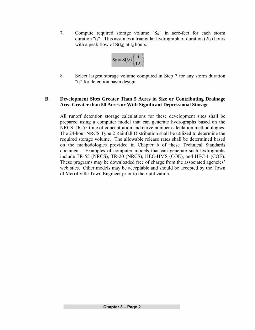
7. Compute required storage volume "SR" in acre-feet for each storm duration "td". This assumes a triangular hydrograph of duration (2td) hours with a peak flow of S(td) at td hours.
( ) ⎟⎠⎞
⎜⎝⎛=12dttSS dR
8. Select largest storage volume computed in Step 7 for any storm duration
"td" for detention basin design.
B. Development Sites Greater Than 5 Acres in Size or Contributing Drainage Area Greater than 50 Acres or With Significant Depressional Storage
All runoff detention storage calculations for these development sites shall be prepared using a computer model that can generate hydrographs based on the NRCS TR-55 time of concentration and curve number calculation methodologies. The 24-hour NRCS Type 2 Rainfall Distribution shall be utilized to determine the required storage volume. The allowable release rates shall be determined based on the methodologies provided in Chapter 6 of these Technical Standards document. Examples of computer models that can generate such hydrographs include TR-55 (NRCS), TR-20 (NRCS), HEC-HMS (COE), and HEC-1 (COE). These programs may be downloaded free of charge from the associated agencies’ web sites. Other models may be acceptable and should be accepted by the Town of Merrillville Town Engineer prior to their utilization.

Chapter 4 – Page 1
STORM SEWER DESIGN STANDARDS AND SPECIFICATIONS
All storm sewers, whether private or public, and whether constructed on private or public property shall conform to the design standards and other requirements contained herein.
A. Design Storm Frequencies
1. All storm sewers, inlets, catch basins, and street gutters shall accommodate (subject to the “allowable spread” provisions discussed later in this Section), as a minimum, peak runoff from a 24-hour, 10-year return frequency storm calculated based on methodology described in Chapter 2. Additional discharges to storm sewer systems allowed in Section L below of this Section must be considered in all design calculations. For Rational Method analysis, the duration shall be equal to the time of concentration for the drainage area. In computer based analysis, the duration is as noted in the applicable methodology associated with the computer program.
2. Culverts shall be capable of accommodating peak runoff from a 24-hour,
50-year frequency storm when crossing under a road which is part of the INDOT Rural Functional Classification System or is classified as freeway, arterial, and/or collectors by the Town of Merrillville Zoning Ordinance or provides the only access to and from any portion of any commercial or residential developments.
3. For portions of the system considered minor drainage systems, the
allowable spread of water on Collector Streets is limited to maintaining two clear 10-foot moving lanes of traffic. One lane is to be maintained on Local Roads, while other access lanes (such as a subdivision cul-de-sac) can have a water spread equal to one-half of their total width. An overflow channel/swale between sag inlets and overflow paths or basin shall be provided at sag inlets so that the maximum depth of water that might be ponded in the street sag shall not exceed 7 inches measured from elevation of gutter.
4. Facilities functioning as a major drainage system as defined in Appendix
A must also meet IDNR design standards.
Chapter Four

Chapter 4 – Page 2
B. Manning's Equation
Determination of hydraulic capacity for storm sewers sized by the
Rational Method analysis must be done using Manning's Equation. where:
Then: Where:
Q = capacity in cubic feet per second
V = mean velocity of flow in feet per second
A = cross sectional area in square feet
R = hydraulic radius in feet
S = slope of the energy grade line in feet per foot
n = Manning's "n" or roughness coefficient
The hydraulic radius, R, is defined as the cross sectional area of flow divided by the wetted flow surface or wetted perimeter. Allowable "n" values and maximum permissible velocities for storm sewer materials are listed in Table 4-1.
C. Backwater Method for Pipe System Analysis
For hydraulic analysis of existing or proposed storm drains which possess submerged outfalls, a more sophisticated design/analysis methodology than Manning’s equation will be required. The backwater analysis method provides a more accurate estimate of pipe flow by calculating individual head losses in pipe systems that are surcharged and/or have submerged outlets. These head losses are added to a known downstream water surface elevation to give a design water surface elevation for a given flow at the desired upstream location. Total head losses may be determined as follows:
Total head loss = frictional loss + manhole loss + velocity head loss + junction
loss
V = (1.486/n)(R2/3 )(S1/2)
Q=(V)(A)

Chapter 4 – Page 3
TABLE 4-1
Typical Values of Manning’s “n”
Material
Manning’s
“n”
Maximum Velocities
(feet/second)
Closed Conduits
Concrete
0.013
10
Vitrified Clay
0.013
10
HDPE
0.012
10
PVC
0.011
10
Circular CMP, Annular Corrugations, 2 2/3 x ½ inch
Unpaved
0.024
7
25% Paved
0.021
7
50% Paved
0.018
7
100% Paved
0.013
7
Concrete Culverts
0.013
10
HDPE or PVC
0.012
10
Open Channels
Concrete, Trowel Finish
0.013
10
Concrete, Broom Finish
0.015
10
Gunite
0.018
10
Riprap Placed
0.030
10
Riprap Dumped
0.035
10
Gabion
0.028
10
New Earth (1)
0.025
4
Existing Earth (2)
0.030
4
Dense Growth of Weeds
0.040
4
Dense Weeds and Brush
0.040
4
Swale with Grass
0.035
4
Source of manning “n” values: HERPICC Stormwater Drainage Manual, July 1995. (1) New earth (uniform, sodded, clay soil) (2) Existing earth (fairly uniform, with some weeds). Various computer modeling programs such as HYDRA,
ILLUDRAIN, and STORMCAD are available for analysis of storm drains under these conditions. Computer models to be utilized, other than those listed, must be accepted by the Town of Merrillville Drainage Board and/or Town of Merrillville Town Engineer.
Chapter 4 – Page 4
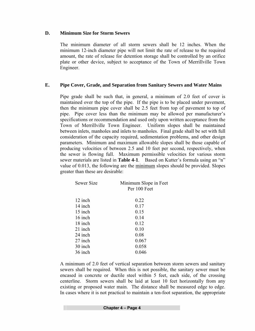
D. Minimum Size for Storm Sewers
The minimum diameter of all storm sewers shall be 12 inches. When the minimum 12-inch diameter pipe will not limit the rate of release to the required amount, the rate of release for detention storage shall be controlled by an orifice plate or other device, subject to acceptance of the Town of Merrillville Town Engineer.
E. Pipe Cover, Grade, and Separation from Sanitary Sewers and Water Mains
Pipe grade shall be such that, in general, a minimum of 2.0 feet of cover is maintained over the top of the pipe. If the pipe is to be placed under pavement, then the minimum pipe cover shall be 2.5 feet from top of pavement to top of pipe. Pipe cover less than the minimum may be allowed per manufacturer’s specifications or recommendation and used only upon written acceptance from the Town of Merrillville Town Engineer. Uniform slopes shall be maintained between inlets, manholes and inlets to manholes. Final grade shall be set with full consideration of the capacity required, sedimentation problems, and other design parameters. Minimum and maximum allowable slopes shall be those capable of producing velocities of between 2.5 and 10 feet per second, respectively, when the sewer is flowing full. Maximum permissible velocities for various storm sewer materials are listed in Table 4-1. Based on Kutter’s formula using an “n” value of 0.013, the following are the minimum slopes should be provided. Slopes greater than these are desirable: Sewer Size Minimum Slope in Feet Per 100 Feet 12 inch 0.22 14 inch 0.17 15 inch 0.15 16 inch 0.14 18 inch 0.12 21 inch 0.10 24 inch 0.08 27 inch 0.067 30 inch 0.058 36 inch 0.046 A minimum of 2.0 feet of vertical separation between storm sewers and sanitary sewers shall be required. When this is not possible, the sanitary sewer must be encased in concrete or ductile steel within 5 feet, each side, of the crossing centerline. Storm sewers shall be laid at least 10 feet horizontally from any existing or proposed water main. The distance shall be measured edge to edge. In cases where it is not practical to maintain a ten-foot separation, the appropriate

Chapter 4 – Page 5
reviewing agency may allow deviation on a case-by-case basis, if supported by data from the design engineer. Such deviation may allow installation of the storm sewer closer to a water main, provided that the water main is in a separate trench or on an undisturbed earth shelf located on one side of the storm sewer and at the elevation so the bottom of the water main is at least 18 inches above the top of the storm sewer.
F. Alignment
Storm sewers shall be straight between manholes and/or inlets. G. Manholes/Inlets
All Inlets must be pre-stamped with an appropriate “clean water” message. Manholes and/or inlets shall be installed to provide human access to continuous underground storm sewers for the purpose of inspection and maintenance. The casting access minimum inside diameter shall be no less than 36 inches or a rectangular opening of no less than 22 inches by 22 inches. Manholes shall be provided at the following locations:
1. Where two or more storm sewers converge. 2. Where pipe size or the pipe material changes.
3. Where a change in horizontal alignment occurs. 4. Where a change in pipe slope occurs.
5. At intervals in straight sections of sewer, not to exceed the maximum allowed. The maximum distance between storm sewer manholes shall be as shown in Table 4-2.
TABLE 4-2
Maximum Distance Between Manholes
Size of Pipe
(Inches)
Maximum Distance
(Feet)
12 through 42
400
48 and larger
600

Chapter 4 – Page 6
In addition to the above requirements, a minimum drop of 0.1 foot through manholes and inlet structures should be provided. When changing pipe size, match crowns of pipes, unless detailed modeling of hydraulic grade line shows that another arrangement would be as effective. Pipe slope should not be so steep that inlets surcharge (i.e. hydraulic grade line should remain below rim elevation).
6. Manhole/inlet inside sizing shall be as shown in Table 4-3.
TABLE 4-3
Manhole/Inlet Inside Sizing
Depth of Structure
Minimum Diameter
Minimum Square Opening
Less than 5 feet
36 inches
36" x 36"
5 feet or more
48 inches
48" x 48"
H. Inlet Sizing and Spacing
Inlets or drainage structures shall be utilized to collect surface water through grated openings and convey it to storm sewers, channels, or culverts. The inlet grate opening provided shall be adequate to pass the design 10-year flow with 50% of the sag inlet areas clogged. An overload channel from sag inlets to the overflow channel or basin shall be provided at sag inlets. Inlet design and spacing may be done using the hydraulic equations by manufacturers or orifice/weir equations. Use of the U.S. Army Corps of Engineers HEC-12 computer program is also an acceptable method. Gutter spread on continuous grades may be determined using the Manning's equation, or by using Figure 4-1. Further guidance regarding gutter spread calculation may be found in the latest edition of HERPICC Stormwater Drainage Manual, available from the Local Technical Assistance Program (LTAP). At the time of printing of this document, contact information for LTAP was:
Indiana LTAP
Purdue University Toll-Free: (800) 428-7369 (Indiana only)
Phone: (765) 494-2164 Fax: (765) 496-1176
Email: [email protected] Website: www.purdue.edu/INLTAP/
Chapter 4 – Page 7
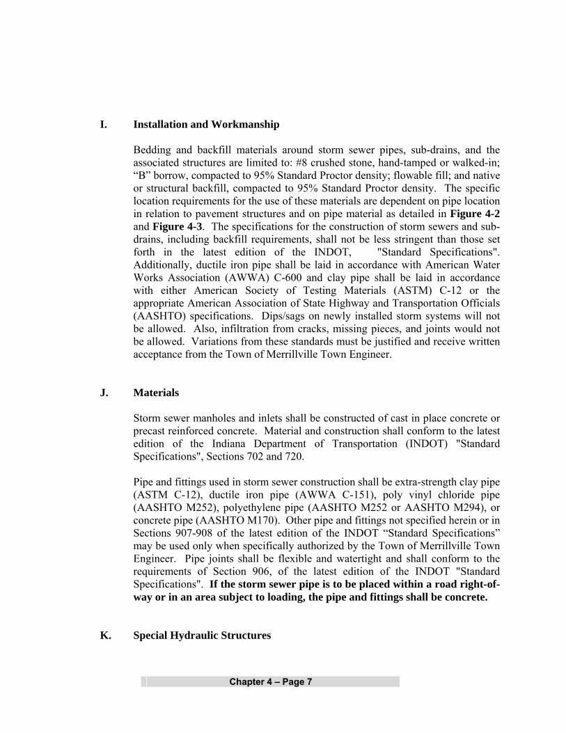
I. Installation and Workmanship
Bedding and backfill materials around storm sewer pipes, sub-drains, and the associated structures are limited to: #8 crushed stone, hand-tamped or walked-in; “B” borrow, compacted to 95% Standard Proctor density; flowable fill; and native or structural backfill, compacted to 95% Standard Proctor density. The specific location requirements for the use of these materials are dependent on pipe location in relation to pavement structures and on pipe material as detailed in Figure 4-2 and Figure 4-3. The specifications for the construction of storm sewers and sub-drains, including backfill requirements, shall not be less stringent than those set forth in the latest edition of the INDOT, "Standard Specifications". Additionally, ductile iron pipe shall be laid in accordance with American Water Works Association (AWWA) C-600 and clay pipe shall be laid in accordance with either American Society of Testing Materials (ASTM) C-12 or the appropriate American Association of State Highway and Transportation Officials (AASHTO) specifications. Dips/sags on newly installed storm systems will not be allowed. Also, infiltration from cracks, missing pieces, and joints would not be allowed. Variations from these standards must be justified and receive written acceptance from the Town of Merrillville Town Engineer.
J. Materials
Storm sewer manholes and inlets shall be constructed of cast in place concrete or precast reinforced concrete. Material and construction shall conform to the latest edition of the Indiana Department of Transportation (INDOT) "Standard Specifications", Sections 702 and 720.
Pipe and fittings used in storm sewer construction shall be extra-strength clay pipe (ASTM C-12), ductile iron pipe (AWWA C-151), poly vinyl chloride pipe (AASHTO M252), polyethylene pipe (AASHTO M252 or AASHTO M294), or concrete pipe (AASHTO M170). Other pipe and fittings not specified herein or in Sections 907-908 of the latest edition of the INDOT “Standard Specifications” may be used only when specifically authorized by the Town of Merrillville Town Engineer. Pipe joints shall be flexible and watertight and shall conform to the requirements of Section 906, of the latest edition of the INDOT "Standard Specifications". If the storm sewer pipe is to be placed within a road right-of-way or in an area subject to loading, the pipe and fittings shall be concrete.
K. Special Hydraulic Structures

Chapter 4 – Page 8
Special hydraulic structures required to control the flow of water in storm runoff drainage systems include junction chambers, drop manholes, stilling basins, and other special structures. The use of these structures shall be limited to those locations justified by prudent planning and by careful and thorough hydraulic engineering analysis. Certification of special structures by a certified Structural Engineer may also be required.
L. Connections to Storm Sewer System
To allow any connections to the storm sewer system, provisions for the connections shall be shown in the drainage calculations for the system. Specific language shall be provided in the protective covenants, on the record plat, or with the parcel deed of record, noting the ability or inability of the system to accommodate any permitted connections, for example, sump pumps and footing drains.
1. Sump pumps installed to receive and discharge groundwater or other
stormwater shall be connected to the storm sewer where possible or discharged into a designated storm drainage channel/swale. Sump pumps installed to receive and discharge floor drain flow or other sanitary sewage shall be connected to the sanitary sewers. A sump pump shall be used for one function only, either the discharge of stormwater or the discharge of sanitary sewage.
2. Footing drains and perimeter drains shall be connected to Manholes or
Curb inlets, where possible, or to designated storm sewers or discharged into designated storm drainage channels/swales.
3. All roof downspouts, roof drains, or roof drainage piping shall
discharge onto the ground and shall not be directly connected to the storm drainage system. Variation from this requirement may be requested and granted by the Town of Merrillville Town Engineer in special circumstances. No downspouts or roof drains shall be connected to the sanitary sewers.
4. Swimming Pool drains shall not be connected to the storm sewers.
In addition, none of the above mentioned devices shall be connected to any street underdrains, unless specifically authorized by the Town of Merrillville Town Engineer.
M. Drainage System Overflow Design

Chapter 4 – Page 9
Overflow path/ponding areas throughout the development resulting from a 100-year storm event, calculated based on all contributing drainage areas, on-site and off-site, in their proposed or reasonably anticipated land use and with storm pipe system assumed completely plugged, shall be determined, clearly shown as hatched area on the plans, and a minimum width of 30 feet along the centerline of the flow path contained in permanent drainage easements. A statement shall be added to the plat that would refer the viewer to the construction plans to see the entire extent of overflow path as hatched areas. No fences or landscaping can be constructed within the easement areas that may impede the free flow of Stormwater. These areas are to be maintained by the property owners or be designated as common areas that are to be maintained by the homeowners association. The Lowest Adjacent Grade for all residential, commercial, or industrial buildings shall be set a minimum of 1 foot above the noted overflow path/ponding elevation.
The overflow path/ponding may be modeled as successive series of natural ponds
and open channel segments. Ponds should be modeled similar to that discussed for modeling depressional areas in Chapter 6. Channels should be modeled according to modeling techniques discussed in Chapter 5. The calculations for determining the 100-year overflow path/ponding elevations may be based on hand calculation methods utilizing normal depth calculations and storage routing techniques or performed by computer models. Examples of computer models that either individually or in combination with other models can handle the required computations include TR-20, HEC-HMS, and HEC-1, combined with HEC-RAS. Other models may be acceptable and should be accepted by the Town of Merrillville Town Engineer prior to their utilization.
Values in Table 4-4 may be utilized as an alternative to the above-noted detailed
calculations for determining the required pad elevations of buildings near an overflow path.
TABLE 4-4
Building Pad Elevations With Respect to Overflow Path Invert Elevations
Drainage Area (acres)
Building Pad Above Overflow Path
Invert (ft.)
Building Pad Above
Overflow Path Invert, if Overflow Path is in the
Street (ft.)
Up to 5
2.5
1.5
6-10
3.0
1.5

Chapter 4 – Page 10
Building Pad Elevations With Respect to Overflow Path Invert Elevations
Drainage Area (acres)
Building Pad Above Overflow Path
Invert (ft.)
Building Pad Above
Overflow Path Invert, if Overflow Path is in the
Street (ft.)
11-15
3.25
1.75
16-20
3.5
1.75
21-30
4.0
2.0
30-50
4.25
2.0
If Table 4-4 is used, the Town of Merrillville Town Engineer reserves the right to
require independent calculations to verify that the proposed building pads provide approximately 1 foot of freeboard above the anticipated overflow path/ponding elevations.
In the case of existing upstream detention, an allowance equivalent to the reduction in flow rate provided may be made for upstream detention only when: (1) such detention and release rate have previously been accepted by the Town of Merrillville Town Engineer official charged with the approval authority at the time of the acceptance, and (2) evidence of its construction and maintenance can be shown.

Chapter 4 – Page 11
FIGURE 4-1 Street and Gutter Capacities (continuous grade)

Chapter 4 – Page 12
FIGURE 4-2 Bedding and Backfill Standards for Storm Sewers
Chapter 4 – Page 13
FIGURE 4-3 Bedding and Backfill Standards for Sub-drains under Swales

Chapter 5 – Page 1
OPEN CHANNEL DESIGN STANDARDS AND SPECIFICATIONS
All channels, whether private or public, and whether constructed on private or public land, shall conform to the design standards and other design requirements contained herein. A. Design Storm Frequencies
1. All channels and swales shall accommodate, as a minimum, peak runoff from a 24-hour, 10-year return frequency storm calculated based on methodology described in Chapter 2. For Rational Method analysis, the storm duration shall be equal to the time of concentration for the drainage area. In computer-based analysis, the duration is as noted in the applicable methodology associated with the computer program.
2. Channels with a carrying capacity of more than 30 cfs at bank-full stage
shall be capable of accommodating peak runoff for a 24-hour, 50-year return frequency storm within the drainage easement.
3. Channel facilities functioning as a major drainage system, as defined in
Appendix A, must also meet IDNR design standards. 4. The 10-year storm design flow for residential rear and side lot swales shall
not exceed 4 cfs. The maximum length of rear and side lot swales before reaching any inlet shall not exceed 400 feet.
5. Regardless of minimum design frequencies stated above, the performance
of all parts of drainage system shall be checked for the 100-year flow conditions to insure that all buildings are properly located outside the 100-year flood boundary and that flow paths are confined to designated areas with sufficient easement.
B. Manning's Equation
The waterway area for channels shall be determined using Manning's Equation, where:
A = Q/V
Chapter Five

Chapter 5 – Page 2
A = Waterway area of channel in square feet Q = Discharge in cubic feet per second (cfs)
V = Steady-State channel velocity, as defined by Manning’s Equation (See
Chapter 4) C. Backwater Method for Drainage System Analysis
The determination of 100-year water surface elevation along channels and swales shall be based on accepted methodology and computer programs designed for this purpose. Computer programs HEC-RAS, HEC-2, and ICPR are preferred programs for conducting such backwater analysis. The use of other computer models must be accepted in advance by the Town of Merrillville Town Engineer.
D. Channel Cross-Section and Grade 1. The required channel cross-section and grade are determined by the design
capacity, the material in which the channel is to be constructed, and the requirements for maintenance. A minimum depth may be required to provide adequate outlets for subsurface drains, tributary ditches, or streams. The channel grade shall be such that the velocity in the channel is high enough to prevent siltation but low enough to prevent erosion. Velocities less than 2 feet per second are not acceptable, as siltation will take place and ultimately reduce the channel cross-section area. The maximum permissible velocities in vegetated-lined channels are shown in Table 5-1. In addition to existing runoff, the channel design should incorporate increased runoff due to the proposed development.
2. Where depth of design flow is slightly below critical depth, channels shall
have freeboard adequate to cope with the effect of hydraulic jumps.
3. Along the streets and roads, the bottom of the ditch should be low enough to install adequately-sized driveway culverts without creating "speed bumps". The driveway culvert inverts shall be designed to adequately consider upstream and downstream culvert elevations.
4. Flow of a channel into a closed system is prohibited, unless runoff rate and
head loss computations demonstrate the closed conduit to be capable of carrying the 100-year channel flow for developed conditions, either entirely or in combination with a defined overflow channel, with no reduction of velocity.

Chapter 5 – Page 3
TABLE 5-1
Maximum Permissible Velocities in Vegetal-Lined Channels (1)
Permissible Velocity (2)
Cover
Channel Slope Range
(Percent) (3)
Erosion
Resistant Soils (ft. per sec.)
(4)
Easily
Eroded Soils (ft. per sec.)
(4)
Bermuda Grass
0-5 5-10
Over 10
8 7 6
6 5 4
Bahia Buffalo Grass Kentucky Bluegrass Smooth Brome Blue Grama
0-5 5-10
Over 10
7 6 5
5 4 3
Grass Mixture Reed Canary Grass
(3) 0-5 5-10
5 4
4 3
Lespedeza Sericea Weeping Lovegrass Yellow Bluestem Redtop Alfalfa Red Fescue
(4)
0-5
5-10
3.4
2.5
Common Lespedeza (5) Sudangrass (5)
(6) 0-5
3.5
2.5
(1) From Soil Conservation Service, SCS-TP-61, "Handbook of Channel Design for Soil and
Water Conservation". (2) Use velocities exceeding 5 feet per second only where good channel ground covers and
proper maintenance can be obtained. (3) Do not use on slopes steeper than 10 percent except for vegetated side slopes in
combination with a stone, concrete, or highly resistant vegetative center section. (4) Do not use on slopes steeper than 5 percent except for vegetated side slopes in
combination with a stone, concrete, or highly resistant vegetative center section. (5) Annuals - use on mild slopes or as temporary protection until permanent covers are
established. (6) Use on slopes steeper than 5 percent is not recommended.

Chapter 5 – Page 4
E. Side Slopes 1. Earthen channel and swale side slopes shall be no steeper than 3 horizontal
to 1 vertical (3:1). Flatter slopes may be required to prevent erosion and for ease of maintenance.
2. Where channels will be lined with riprap, concrete, or other acceptable
lining method, side slopes shall be no steeper than 2 horizontal to 1 vertical (2:1) with adequate provisions made for weep holes.
3. Side slopes steeper than 2 horizontal to 1 vertical (2:1) may be used for
lined channels provided that the side lining is designed and constructed as a structural retaining wall with provisions for live and dead load surcharge.
4. When the design discharge produces a depth of greater than three (3) feet
in the channel, appropriate safety precautions shall be added to the design criteria based on reasonably anticipated safety needs.
F. Channel Stability 1. Characteristics of a stable channel are: a] It neither promotes sedimentation nor degrades the channel bottom
and sides.
b] The channel banks do not erode to the extent that the channel cross-section is changed appreciably.
c] Excessive sediment bars do not develop. d] Excessive erosion does not occur around culverts, bridges, outfalls
or elsewhere. e] Gullies do not form or enlarge due to the entry of uncontrolled
flow to the channel.
2. Channel stability shall be determined for an aged condition and the velocity shall be based on the design flow or the bankfull flow, whichever is greater, using an "n" value for various channel linings as shown in Tables 4-1 and 5-1. In no case is it necessary to check channel stability for discharges greater than that from a 100-year frequency storm.

Chapter 5 – Page 5
3. Channel stability shall be checked for conditions representing the period immediately after construction. For this stability analysis, the velocity shall be calculated for the expected flow from a 10-year frequency storm on the watershed, or the bankfull flow, whichever is smaller, and the "n" value for the newly constructed channels in fine-grained soils and sands may be determined in accordance with the "National Engineering Handbook 5, Supplement B, Soil Conservation Service" and shall not exceed 0.025. This reference may be obtained by contacting the National Technical Information Service in Springfield. The allowable velocity in the newly constructed channel may be increased by a maximum of 20 percent to reflect the effects of vegetation to be established under the following conditions:
a] The soil and site in which the channel is to be constructed are
suitable for rapid establishment and support of erosion controlling vegetation.
b] Species of erosion controlling vegetation adapted to the area, and
proven methods of establishment are shown.
c] The channel design includes detailed plans for establishment of vegetation on the channel side slopes.
G. Drainage of Swales
Minimum swale slopes are 0.5%. All flow shall be confined to the specific easements associated with each rear and side lot swale that are part of the minor drainage system. Unless designed to act as a stormwater quality BMP, vegetated swales with a slope less than 1.0 % shall have tile underdrains to dry the swales. (See Figure 4-3). Tile lines may be outletted through a drop structure at the ends of the swale or through a standard tile outlet. Further guidance regarding this subject may be found in the latest edition of the Indiana Drainage Handbook.
H. Appurtenant Structures
The design of channels will include provisions for operation and maintenance and the proper functioning of all channels, laterals, travelways, and structures associated with the project. Recessed inlets and structures needed for entry of surface and subsurface flow into channels without significant erosion or degradation shall be included in the design of channel improvements. The design will also provide for necessary floodgates, water level control devices, and any other appurtenance structure affecting the functioning of the channels and the attainment of the purpose for which they are built.

Chapter 5 – Page 6
The effects of channel improvements on existing culverts, bridges, buried cables, pipelines, and inlet structures for surface and subsurface drainage on the channel being improved and laterals thereto shall be evaluated to determine the need for modification or replacement. Culverts and bridges which are modified or added as part of channel improvement projects shall meet reasonable standards for the type of structure, and shall have a minimum capacity equal to the design discharge or governmental agency design requirements, whichever is greater.
I. Deposition of Spoil
Spoil material resulting from clearing, grubbing, and channel excavation shall be disposed of in a manner that will:
1. Minimize overbank wash.
2. Provide for the free flow of water between the channel and floodplain
boundary unless the valley routing and water surface profiles are based on continuous dikes being installed.
3. Not hinder the development of travelways for maintenance.
4. Leave the right-of-way in the best condition feasible, consistent with the
project purposes, for productive use by the owner.
5. Be accepted by the IDNR or COE, if applicable. J. Materials
Materials acceptable for use as channel lining are:
1. Grass 2. Revetment Riprap 3. Concrete 4. Hand Laid Riprap 5. Precast Cement Concrete Riprap 6. Gabions 7. Straw or Coconut Mattings (only until grass is established)
Other lining materials must be accepted in writing by the Town of Merrillville Town Engineer. Materials shall comply with the latest edition of the INDOT, "Standard Specifications".
Chapter 5 – Page 7
K. Drainage System Overflow Design Ponding and overflow path throughout the development resulting from a 100-year
storm event, calculated based on all contributing drainage areas, on-site and off-site, in their proposed or reasonably anticipated land use and with storm pipe system assumed completely plugged, shall be determined, clearly shown as hatched area on the plans, and a 30 feet along the centerline of the overflow path contained in permanent drainage easements. A statement shall be added to the plat that would refer the viewer to the construction plans to see the entire extent of overflow path as hatched areas. No fences or landscaping can be constructed within the easement areas that may impede the free flow of Stormwater. These areas are to be maintained by the property owners or be designated as common areas that are to be maintained by the homeowners association. The Lowest Adjacent Grade for all residential, commercial, or industrial buildings shall be set a minimum of 1 foot above the noted overflow path/ponding elevation.
The overflow path/ponding may be modeled as successive series of natural ponds
and open channel segments. Ponds should be modeled similar to that discussed for modeling depressional areas in Chapter 6. Channels should be modeled according to modeling techniques discussed earlier in this Chapter. The calculations for determining the 100-year overflow path/ponding elevations may be based on hand calculation methods utilizing normal depth calculations and storage routing techniques or performed by computer models. Examples of computer models that either individually or in combination with other models can handle the required computations include TR-20, HEC-HMS, and HEC-1, combined with HEC-RAS. Other models may be acceptable and should be accepted by the Town of Merrillville Town Engineer prior to their utilization.
Values in Table 4-4 may be utilized as an alternative to the above-noted detailed
calculations for determining the required pad elevations of buildings near an overflow path.
If Table 4-4 is used, the Town of Merrillville Town Engineer reserves the right to
require independent calculations to verify that the proposed building pads provide approximately 1 foot of freeboard above the anticipated overflow path/ponding elevations.
In the case of existing upstream detention, an allowance equivalent to the reduction in flow rate provided may be made for upstream detention only when: (1) such detention and release rate have previously been accepted by the Town of Merrillville Town Engineer official charged with the approval authority at the time of the acceptance, and (2) evidence of its construction and maintenance can be shown.

Chapter 6 – Page 1
STORMWATER DETENTION DESIGN STANDARDS
The following shall govern the design of any improvement with respect to the detention of stormwater runoff. Basins shall be constructed to temporarily detain the stormwater runoff that exceeds the maximum peak release rate authorized by this Ordinance. The required volume of storage provided in these basins, together with such storage as may be authorized in other on-site facilities, shall be sufficient to control excess runoff from the 10-year or 100-year storm as explained below in Section “B.”. Also, basins shall be constructed to provide adequate capacity to allow for sediment accumulation resulting from development and to permit the pond to function for reasonable periods between cleanings. A. Acceptable Detention Facilities
The increased stormwater runoff resulting from a proposed development should be detained on-site by the provisions of appropriate wet bottom or dry bottom detention facilities, parking lots, or other acceptable techniques. Measures that retard the rate of overland flow and the velocity in runoff channels shall also be used to partially control runoff rates.
B. Allowable Release Rates
1. General Release Rates
Control devices shall limit the discharge to a rate such that the post-developed release rate from the site is no greater than 0.2 cfs per acre of development for 0-100 year return interval storms. For sites where the pre-developed area has more than one (1) outlet, the release rate should be computed based on pre-developed discharge to each outlet point. The computed release rate for each outlet point shall not be exceeded at the respective outlet point even if the post developed conditions would involve a different arrangement of outlet points.
2. Site-Specific Release Rates for Sites with Depressional Storage
For sites where depressional storage exists, the general release rates provided above may have to be further reduced. If depressional storage exists at the site, site-specific release rates must be calculated according to methodology described in Chapter 2, accounting for the depressional storage by modeling it as a pond whose outlet is a weir at an elevation that stormwater can currently overflow the depressional storage area. Post developed release rate for sites with depressional storage shall be the 2-year pre-developed peak runoff rate for the post-developed 100-year
Chapter Six

Chapter 6 – Page 2
storm. In no case shall the calculated site-specific release rates be larger than general release rates provided above.
Note that by definition, the depressional storage does not have a direct gravity outlet but if in agricultural production, it is more than likely drained by a tile and should be modeled as “empty” at the beginning of a storm. The function of any existing depressional storage should be modeled using an event hydrograph model to determine the volume of storage that exists and its effect on the existing site release rate. To prepare such a model, certain information must be obtained, including delineating the tributary drainage area, the stage-storage relationship and discharge-rating curve, and identifying the capacity and elevation of the outlet(s).
The tributary area should be delineated on the best available topographic data. After determining the tributary area, a hydrologic analysis of the watershed should be performed, including, but not limited to: a calculation of the appropriate composite runoff curve number and time of concentration. Stage-storage data for the depressional area should be obtained from the site topography. The outlet should be clearly marked and any calculations performed to create a stage-discharge rating curve must be included with the stormwater submittal.
Also note that for determining the post-developed peak runoff rates, the depressional storage must be assumed to be filled unless the Town of Merrillville Town Engineer can be assured, through dedicated easement, that the noted storage will be preserved in perpetuity.
3. Management of Off-site Runoff
Runoff from all upstream tributary areas (off-site land areas) may be bypassed around the detention/retention facility without attenuation. Such runoff may also be routed through the detention/retention facility, provided that a separate outlet system or channel is incorporated for the safe passage of such flows, i.e., not through the primary outlet of a detention facility. Unless the pond is being designed as a regional detention facility, the primary outlet structure shall be sized and the invert elevation of the emergency overflow weir determined according to the on-site runoff only. Once the size and location of primary outlet structure and the invert elevation of the emergency overflow weir are determined by considering on-site runoff, the 100-year pond elevation is determined by routing the entire inflow, on-site and off-site, through the pond.
Note that the efficiency of the detention/retention facility in controlling the on-site runoff may be severely affected if the off-site area is considerably larger than the on-site area. As a general guidance, on-line detention may not be effective in controlling on-site runoff where the ratio of off-site area
Chapter 6 – Page 3
to on-site area is larger than 5:1. Additional detention (above and beyond that required for on-site area) may be required by the Town of Merrillville Town Engineer when the ratio of off-site area to on-site area is larger than 5:1.
4. Downstream Restrictions
In the event the downstream receiving channel or storm sewer system is inadequate to accommodate the post-developed release rate provided above, then the allowable release rate shall be reduced to that rate permitted by the capacity of the receiving downstream channel or storm sewer system. Additional detention, as determined by the Town of Merrillville Town Engineer, shall be required to store that portion of the runoff exceeding the capacity of the receiving sewers or waterways. When such downstream restrictions are suspected, the Town of Merrillville Town Engineer may require additional analysis to determine the receiving system’s limiting downstream capacity.
If the proposed development makes up only a portion of the undeveloped watershed upstream of the limiting restriction, the allowable release rate for the development shall be in direct proportion to the ratio of its drainage area to the drainage area of the entire watershed upstream of the restriction.
C. General Detention Basin Design Requirements
1. The detention facility shall be designed in such a manor that a minimum
of 90% of the maximum volume of water stored and subsequently released at the design release rate shall not result in a storage duration in excess of 48 hours from the start of the storm unless additional storms occur within the period. In other words, the design shall ensure that a minimum 90% of the original detention capacity is restored within 48 hours from the start of the design 100-year storm.
2. The 100-year elevation of stormwater detention facilities shall be
separated by not less than 25 feet from any building or structure to be occupied. The Lowest Adjacent Grade (including walkout basement floor elevation) for all residential, commercial, or industrial buildings shall be set a minimum of 2 feet above the 100-year pond elevation or 2 feet above the emergency overflow weir elevation, whichever is higher. In addition to the Lowest Adjacent Grade requirements, any basement floor must be at least a foot above the normal water level of any wet-bottom pond.
3. No detention facility or other water storage area, permanent or temporary,
shall be constructed under or within twenty (20) feet of any pole or high voltage electric line. Likewise, poles or high voltage electric lines shall

Chapter 6 – Page 4
not be placed within twenty (20) feet of any detention facility or other water storage area.
4. All stormwater detention facilities shall be separated from any road right-
of-way by no less than one right-of-way width, measured from the top of bank or the 100-year pool if no defined top of bank is present, using the most restrictive right-of-way possible. If the width of the right-of-way is less than 50 feet, then the minimum distance between top of bank and road right-of-way shall be increased to 50 feet. Use of guard rails, berms, or other structural measures may be considered in lieu of the above-noted setbacks.
5. Slopes no steeper than 3 horizontal to 1 vertical (3:1) for safety, erosion
control, stability, and ease of maintenance shall be permitted. 6. Safety screens having a maximum opening of four (4) inches shall be
provided for any pipe or opening to prevent children or large animals from crawling into the structures.
7. Prior to final acceptance, danger signs shall be mounted at appropriate
locations to warn of deep water, possible flood conditions during storm periods, and other dangers that exist. The locations of the noted danger signs shall be shown on the plans.
8. Use of fences around all detention ponds is strongly encouraged to assure
safety. Unless specifically required by the Town of Merrillville Town Engineer,
the decision to use fencing around detention ponds are left to the owner or the developer. Recommendations contained within this document do not relieve the applicant and owner/developer from the responsibility of taking all necessary steps to ensure public safety with regards to such facilities.
9. Outlet control structures shall be designed to operate as simply as possible
and shall require little or no maintenance and/or attention for proper operation. For maintenance purposes, the outlet shall be a minimum of 0.5 foot above the normal water level of the receiving water body. They shall limit discharges into existing or planned downstream channels or conduits so as not to exceed the predetermined maximum authorized peak flow rate.
10. Emergency overflow facilities such as a weir or spillway shall be provided
for the release of exceptional storm runoff or in emergency conditions should the normal discharge devices become totally or partially inoperative. The overflow facility shall be of such design that its operation is automatic and does not require manual attention.

Chapter 6 – Page 5
a] Off-site flows greater than the allowable release rate for the pond
shall be conveyed through the emergency spillway, not through the primary outlet structure. Unless the pond is being designed as a regional detention facility, the primary outlet structure shall be sized and the invert elevation of the emergency overflow weir determined according to the on-site runoff only and all other flows shall be either retained or safely bypassed through the emergency overflow weir.
b] Emergency overflow facilities shall be designed to handle one and
one-quarter (1.25) times the peak inflow discharge and peak flow velocity resulting from the 100-year design storm event runoff from the entire contributing watershed draining to the detention/retention facility, assuming post-development condition on-site and existing condition off-site,.
11. Grass or other suitable vegetative cover shall be provided along the banks
of the detention storage basin. Vegetative cover around detention facilities should be maintained as appropriate.
12. Debris and trash removal and other necessary maintenance shall be
performed on a regular basis to assure continued operation in conformance to design.
13. No residential lots or any part thereof, shall be used for any part of a
detention basin or for the storage of water, either temporary or permanent. D. Additional Requirements for Wet-Bottom Facility Design
Where part of a detention facility will contain a permanent pool of water, all the items required for detention storage shall apply. Also, a controlled positive outlet will be required to maintain the design water level in the wet bottom facility and provide required detention storage above the design water level. However, the following additional conditions shall apply:
1. Facilities designed with permanent pools or containing permanent lakes
shall have a water area of at least one-half (0.5) acre. If fish are to be used to keep the pond clean, a minimum depth of approximately ten (10) feet shall be maintained over at least 25 percent of the pond area. The remaining pond area shall have no extensive shallow areas, except as required to install the safety ramp, safety ledge, and BMPs as required below. Construction trash or debris shall not be placed within the permanent pool.

Chapter 6 – Page 6
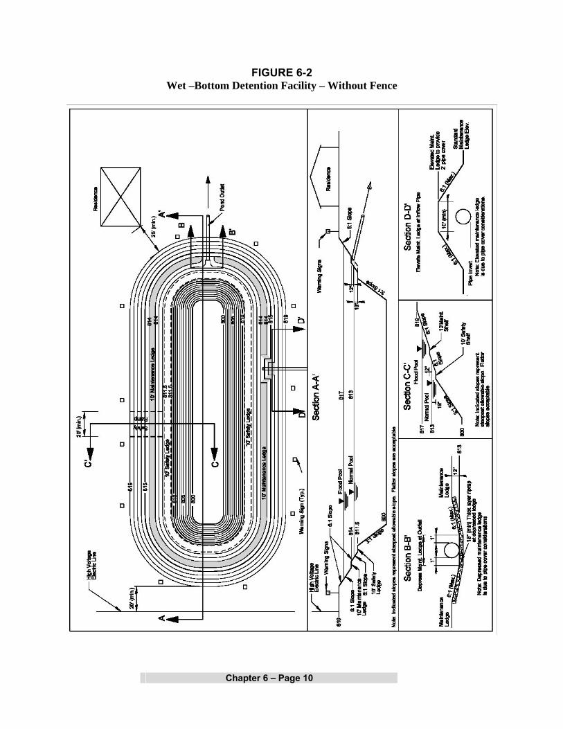
2. A safety ledge six (6) to ten (10) feet in width, depending on the presence of a security fence, is required and shall be installed in all lakes approximately 18 inches below the permanent water level (normal pool elevation). In addition, a similar maintenance ledge 12 inches above the permanent water line shall be provided. The slope between the two ledges shall be stable and of a material such as stone or riprap which will prevent erosion due to wave action. The slopes below the safety ledge shall be 3:1 (horizontal to vertical) or flatter. The slopes above the safety ledge shall be 6:1 or flatter, unless a safety fence is used, in which case the side slopes above the safety ledge (except for the safety ramp area) shall be 3:1 or flatter.
As illustrated in Figures 6-1 and 6-2, the safety ledge is currently required
to be 18 inches below the normal pool and 6-10 feet wide, depending on the presence of a security fence. As an alternative to providing a security fence, the depth of safety ledge could be changed to be anywhere from 0 to 6 inches below normal pool to encourage vegetation growth. Wetland plants can be installed as container grown plants or as seed at the time of construction, or the area can be left to be naturally colonized. When a vegetated ledge is used in lieu of a security fence, the safety ledge width shall be increased to 15 feet to allow more room to stop in the event of accidental entry into the pond. The vegetated ledge might discourage play near the edge of the pond and help stop a wayward bike or sled. Additional benefits to the vegetated ledge are stormwater quality improvement and goose deterrence. In lieu of a vegetated safety ledge, a zone of dense shrubs could be installed around the perimeter of the pond to discourage access. Shrubs and vines with briars and thorns or dense growth patterns make good deterrents.
In lieu of a vegetated safety ledge, a zone of dense shrubs could be
installed around the perimeter of the pond to discourage access. Shrubs and vines with briars and thorns or dense growth patterns make good deterrents.
Special Regulatory Note: Detention ponds that include wetland features will not fall within the jurisdiction of IDEM or COE as long as:
• The pond is clearly identified on plans and in accompanying documentation as a stormwater treatment Best Management Practice (BMP). The pond has not been abandoned, and is maintained as originally designed. The pond is not part of required wetland mitigation. Construction of the pond does not impact existing jurisdictional wetlands or waterways.
Therefore, detention pond maintenance would not require a permit just because wetland features have been included in their construction.

Chapter 6 – Page 7
3. A safety ramp exit from the lake shall be required in all cases and shall have a minimum width of twenty (20) feet and exit slope of 6 horizontal to 1 vertical (6:1). The safety ramp shall be constructed of suitable material to prevent structural instability due to vehicles or wave action.
4. Periodic maintenance is required in lakes to control weed and larval
growth. The facility shall also be designed to provide for the easy removal of sediment that will accumulate during periods of reservoir operation. A means of maintaining the designed water level of the lake during prolonged periods of dry weather may also be required.
5. Methods to prevent pond stagnation, including but not limited to aeration
facilities, shall be included on all wet-bottom ponds. Design calculations to substantiate the effectiveness of proposed aeration facilities shall be submitted with final engineering plans. Agreements for the perpetual operation and maintenance of aeration facilities shall be prepared to the satisfaction of the Town of Merrillville Town Engineer.
6. For visual clarification, refer to Figures 6-1 and 6-2.
E. Additional Requirements for Dry-Bottom Facility Design
In addition to general design requirements, detention facilities that will not contain a permanent pool of water shall comply with the following requirements:
1. Provisions shall be incorporated into facilities for complete interior
drainage of dry bottom facilities, including the provisions of natural grades to outlet structures, longitudinal and transverse grades to perimeter drainage facility, paved gutters, or the installation of subsurface drains.
2. For residential developments, the maximum planned depth of stormwater
stored shall not exceed four (4) feet.
3. In excavated detention facilities, a minimum side slope of 3:1 shall be provided for stability. In the case of valley storage, natural slopes may be considered to be stable.
F. Parking Lot Storage
Paved parking lots may be designed to provide temporary detention storage of stormwater on all or a portion of their surfaces. Outlets for parking lot storage of stormwater will be designed so as to empty the stored waters slowly. Depths of

Chapter 6 – Page 8
storage shall be limited to a maximum depth of seven (7) inches so as to prevent damage to parked vehicles and so that access to parked vehicles is not impaired. Ponding should in general, be confined to those positions of the parking lots farthest from the area served.
G. Detention Facilities in Floodplains
If detention storage is provided within a 100-year floodplain, only the net increase in storage volume above that which naturally existed on the floodplain shall be credited to the development. In order to be hydraulically effective, the rim elevation of such detention pond, including any open spillways, should be at or above the 100-year floodplain elevation and, unless the detention pond storage is provided entirely above the 100-year flood elevation, any pipe outlets must be equipped with a backflow prevention device. A detention pond constructed within the 100-year floodplain and utilizing a backflow prevention device will eliminate the floodplain storage that existed on the detention pond site, and will therefore require compensatory floodplain storage. The detention analysis for a detention pond in the floodplain must consider appropriate tailwater impacts and the effect of any backflow prevention device.

Chapter 6 – Page 9
FIGURE 6-1 Wet –Bottom Detention Facility – With Fence
Chapter 6 – Page 10
FIGURE 6-2 Wet –Bottom Detention Facility – Without Fence

Chapter 6 – Page 11
H. Joint Development of Control Systems
Stormwater control systems may be planned and constructed jointly by two or more developers as long as compliance with this Ordinance is maintained.
I. Diffused Outlets
When the allowable runoff is released in an area that is susceptible to flooding or erosion, the developer may be required to construct appropriate storm drains through such area to avert increased flood hazard caused by the concentration of allowable runoff at one point instead of the natural overland distribution. The requirement of diffused outlet drains shall be at the discretion of the Town of Merrillville Town Engineer.
J. IDNR Requirements
All designs for basins to be constructed in the floodway of a stream with a drainage area of one square mile or more must also satisfy IDNR permit requirements.
K. Allowance for Sedimentation
Detention basins shall be designed with an additional ten (10) percent of available
capacity to allow for sediment accumulation resulting from development and to permit the pond to function for reasonable periods between cleanings. Basins should be designed to collect sediment and debris in specific locations, such as a forebay, so that removal costs are kept to a minimum. For wet-bottom ponds, the sediment allowance may be provided below the permanent pool elevation. No construction trash or debris shall be allowed to be placed within the permanent pool. If the pond is used as a sediment control measure during active construction, the performance sureties will not be released until sediment has been cleaned out of the pond and elevations and grades have been reestablished as noted in the accepted plans.

Chapter 7 – Page 1
EROSION CONTROL PRACTICES AND CONSTRUCTION PHASE BMPs
The requirements contained in this chapter are intended to prevent stormwater pollution resulting from soil erosion and sedimentation or from mishandling of solid and hazardous waste. Practices and measures included herein should assure that no foreign substance, (e.g. sediment, construction debris, chemicals) be transported from a site and allowed to enter any drainageway, whether intentionally or accidentally, by machinery, wind, rain, runoff, or other means. A. POLLUTANTS OF CONCERN DURING CONSTRUCTION The major pollutant of concern during construction is sediment. Natural erosion processes are accelerated at a project site by the construction process for a number of reasons, including the loss of surface vegetation and compaction damage to the soil structure itself, resulting in reduced infiltration and increased surface runoff. Clearing and grading operations also expose subsoils which are often poorly suited to re-establish vegetation, leading to longer term erosion problems. Problems associated with construction site erosion include: transport of pollutants attached to transported sediment; increased turbidity (reduced light) in receiving waters; recreational use impairment. The deposited sediment may pose direct toxicity to wildlife, or smother existing spawning areas and habitat. This siltation also reduces the capacity of waterways, resulting in increased flood hazards to the public. Other pollutants of concern during the construction process are hazardous wastes or hydrocarbons associated with the construction equipment or processes. Examples include concrete washoff, paints, solvents, and hydrocarbons from refueling operations. Poor control and handling of toxic construction materials pose an acute (short-term) or chronic (long-term) risk of death to both aquatic life, wildlife, and the general public.
B. EROSION AND SEDIMENT CONTROL REQUIREMENTS The following principles should govern erosion and sediment control practices on all sites:
1. Sediment-laden water flowing from the site shall be detained by erosion control measures
appropriate to minimize sedimentation.
2. Water shall not be discharged in a manner that causes erosion at or downstream of the point of discharge.
Chapter Seven

Chapter 7 – Page 2
3. All access to building sites that cross a natural watercourse, drainage easement, or
swale/channel shall have a culvert of appropriate size.
4. Wastes or unused building materials, including but not limited to garbage, debris, cleaning wastes, wastewater, toxic materials, and hazardous substances, shall not be carried by runoff from a site. All wastes shall be disposed of in a proper manner. No construction trash or debris shall be allowed to be placed within the permanent pool of the detention/retention ponds. If the pond is used as a sediment control measure during active construction, the performance sureties will not be released until sediment has been cleaned out of the pond and elevations and grades have been reestablished as noted in the accepted plans.
5. Sediment being tracked from a site onto public or private roadways shall be minimized.
This can be accomplished initially by a temporary gravel construction entrance, in addition to a well-planned layout of roads, access drives, and parking areas.
6. Public or private roadways shall be kept cleared of accumulated sediment. Bulk clearing
of sediment shall not include flushing the area with water.
7. All storm drain inlets shall be protected against sedimentation with barriers meeting accepted criteria, standards and specifications.
8. Runoff passing through a site from adjacent areas shall be controlled by diverting it
around disturbed areas, where practical. Diverted runoff shall be conveyed in a manner that will not erode the channel and receiving areas. Alternatively, the existing channel may be left undisturbed or improved to prevent erosion or sedimentation from occurring.
9. Drainageways and swales shall be designed and adequately protected so that their final
gradients and resultant velocities will not cause channel or outlet scouring.
10. All disturbed ground left inactive for fifteen (15) or more days shall be stabilized by seeding, sodding, mulching, covering, or by other equivalent erosion control measures.
11. Appropriate sediment control practices shall be installed prior to any land disturbance and
thereafter whenever necessary.
12. During the period of construction activity at a site, erosion control measures necessary to meet the requirements of this Ordinance shall be maintained by the applicant.
C. COMMON CONTROL PRACTICES All erosion control and stormwater pollution prevention measures required to comply with this Ordinance shall meet the design criteria, standards, and specifications similar to or the same as those outlined in the “Indiana Drainage Handbook” and “Indiana Handbook for Erosion Control

Chapter 7 – Page 3
in Developing Areas”, both published by the Indiana Department of Natural Resources, or other comparable and reputable references. Table 7-1 lists some of the more common and effective practices for preventing stormwater pollution from construction sites. Details of each practice can be found in the Indiana Drainage Handbook, the Indiana Handbook for Erosion Control in Developing Areas, or in Appendix C. These practices should be used to protect every potential pollution pathway to stormwater conveyances.
Table 7-1 Common Stormwater Pollution Control Practices for Construction Sites
Practice No. BMP Description Applicability Fact
Sheet 1 Site Assessment All sites 2 2 Construction Sequencing All sites CN - 101
3 Tree Preservation and Protection Nearly all sites 1
4 Temporary Gravel Construction Entrance Pad All sites 1
5 Wheel Wash All sites CN - 102 6 Silt Fence Small drainage areas 1
7 Surface Roughening Sites with slopes that are to be stabilized with vegetation 1
8 Temporary Seeding Areas of bare soil where additional work is not scheduled to be performed for a minimum of 15 days
1
9 Mulching Temporary surface stabilization 1
10 Erosion Control Blanket (Surface)
Temporary surface stabilization, anchor for mulch 1
11 Temporary Diversion Up-slope and down-slope sides of construction site, above disturbed slopes within construction site
1
12 Rock Check Dam 2 acres maximum contributing drainage area 1 13 Temporary Slope Drain Sites with cut or fill slopes 1 14 Straw Bale Dam Small drainage areas 1 15 Fabric Drop Inlet Protection 1 acre maximum contributing drainage area 1 16 Basket Curb Inlet Protection 1 acre maximum contributing drainage area 1 17 Sandbag Curb Inlet Protection 1 acre maximum contributing drainage area 1 18 Temporary Sediment Trap 5 acre maximum contributing drainage area 1 19 Temporary Sediment Basin 30 acre maximum contributing drainage area 1 20 Dewatering Structure Sites requiring dewatering CN - 103 21 Dust Control All sites 1 22 Spill Prevention and Control All sites CN - 104 23 Solid Waste Management All sites CN - 105
24 Hazardous Waste Management All sites CN - 106
Fact sheet Location: 1. Indiana Handbook for Erosion Control in Developing Areas, 1992 or later 2. Indiana Drainage Handbook, 1999 or later
Chapter 7 – Page 4
D. INDIVIDUAL LOT CONTROLS Although individual lots within a larger development may not appear to contribute as much sediment as the overall development, the cumulative effect of lot development is of concern. From the time construction on an individual lot begins, until the individual lot is stabilized, the builder must take steps to:
• protect adjacent properties from sedimentation • prevent mud/sediment from depositing on the street • protect drainageways from erosion and sedimentation • prevent sediment laden water from entering storm sewer inlets.
This can be accomplished using numerous erosion and sediment control measures. A standard erosion control plan for individual lots is provided in Appendix B. The standard plan includes perimeter silt fence, stabilized construction entrance, curb inlet protection, drop inlet protection, stockpile containment, stabilized drainage swales, downspout extensions, temporary seeding and mulching, and permanent vegetation. Every relevant measure should be installed at each individual lot site. Construction sequence on individual lots should be as follows:
1. Clearly delineate areas of trees, shrubs, and vegetation that are to be undisturbed. To prevent root damage, the areas delineated for tree protection should be at least the same diameter as the crown.
2. Install perimeter silt fence at construction limits. Position the fence to intercept runoff prior to entering drainage swales.
3. Avoid disturbing drainage swales if vegetation is established. If drainage swales are bare, install erosion control blankets or sod to immediately stabilize.
4. Install drop inlet protection for all inlets on the property. 5. Install curb inlet protection, on both sides of the road, for all inlets along property
frontage and the along the frontage of adjacent lots. 6. Install gravel construction entrance that extends from the street to the building pad. 7. Perform primary grading operations. 8. Contain erosion from any soil stockpiles created on-site with silt fence around the base. 9. Establish temporary seeding and straw mulch on disturbed areas. 10. Construct the home and install utilities. 11. Install downspout extenders once the roof and gutters have been constructed. Extenders
should outlet to a stabilized area. 12. Re-seed any areas disturbed by construction and utilities installation with temporary seed
mix within 3 days of completion of disturbance. 13. Grade the site to final elevations. 14. Install permanent seeding or sod.
All erosion and sediment control measures must be properly maintained throughout construction. Temporary and permanent seeding should be watered as needed until established. For further information on individual lot erosion and sediment control, please see the “Individual Lot Erosion and Sediment Control Plan and Certification” form in Appendix B or the IDNR,

Chapter 7 – Page 5
Division of Soil Conservation’s pamphlet titled “Erosion and Sediment control for Individual Building Sites”.

Chapter 8 – Page 1
POST-CONSTRUCTION WATER QUALITY BMPs
A. INTRODUCTION Town of Merrillville has adopted a policy that the control of stormwater runoff quality will be based on the management of Total Suspended Solids (TSS). This requirement is being adopted as the basis of the Town of Merrillville storm water quality management program for all areas of jurisdiction. This section of the manual establishes minimum standards for the selection and design of construction water quality BMPs. The information provided in this chapter establishes performance criteria for stormwater quality management and procedures to be followed when preparing a BMP plan for compliance. Post-Construction BMPs must be sized to treat the water quality volume, WQv, for detention-based BMPs or the water quality discharge, Qwq, for flow-through BMPs. Chapter 9 provides the methodology for calculating the WQv and Qwq values.
BMPs noted in this chapter refer to post-construction BMPs, which continue to treat stormwater after construction has been completed and the site has been stabilized. Installing certain BMPs, such as bioretention areas and sand filters, prior to stabilization can cause failure of the measure due to clogging from sediment. If such BMPs are installed prior to site stabilization, they should be protected by traditional erosion control measures. Conversely, detention ponds and other BMPs can be installed during construction and used as sediment control measures. In those instances, the construction sequence must require that the pond is cleaned out with pertinent elevations and storage and treatment capacities reestablished as noted in the accepted stormwater management plan. B. INNOVATIVE BMPs BMPs not previously accepted by the Town of Merrillville Town Engineer must be certified by a professional engineer licensed in State of Indiana and accepted through the Town of Merrillville Town Engineer. ASTM standard methods must be followed when verifying performance of new measures. New BMPs, individually or in combination, must meet the 80% TSS removal rate at 50-125 micron range (silt/fine sand) without reintrainment and must have a low to medium maintenance requirement to be considered by the Town of Merrillville Town Engineer. Testing to establish the TSS removal rate must be conducted by an independent testing facility, not the BMP manufacturer. C. PRE-APROVED BMPs Town of Merrillville has designated 12 pre-approved BMP methods to be used alone or in combination to achieve the 80% TSS removal stormwater quality goals for a given project.
Chapter Eight

Chapter 8 – Page 2
These BMP measures are listed along with their anticipated average TSS removal rates in Table 8-1. Pre-approved BMPs have been proven/are assumed to achieve the average TSS removal rates indicated in Table 8-1. Applicants desiring to use a different TSS removal rate for these BMPs must follow the requirements discussed above for Innovative BMPs. Details regarding the applicability and design of these pre-approved BMPs are contained within fact sheets presented in Appendix D. Note that a single BMP measure may not be adequate to achieve the water quality goals for a project. It is for this reason that a “treatment train”, a number of BMPs in series, is often required for a project.

Chapter 8 – Page 3
TABLE 8-1 Pre-approved Post-construction BMPs
BMP Description Anticipated
Average % TSS Removal RateE
BioretentionA 75 Constructed Wetland 65 Underground detention 70 Extended Dry DetentionB 72 Infiltration BasinA 87 Infiltration TrenchA 87 Media Filtration – Underground Sand 80 Media Filtration – Surface Sand 83 Storm Drain InsertD NAC Filter Strip 48 Vegetated Swale 60 Wet Detention 80
Notes:
A. Based on capture of 0.5-inch of runoff volume as best available data. Effectiveness directly related to captured runoff volume, increasing with larger capture volumes.
B. Test results are for three types of ponds: extended wet detention, wet pond and extended dry detention
C. NA may indicate that the BMP is not applicable for the pollutant, but may also indicate that the information is simply Not Available. Independent testing should be provided, rather than the manufacturer’s testing data.
D. Must provide vendor data for removal rates. E. Removal rates shown are based on typical results. These rates are also dependent on proper
installation and maintenance. The ultimate responsibility for determining whether additional measures must be taken to meet the Ordinance requirements for site-specific conditions rests with the applicant.
REFERENCES
1. Bell, W., L. Stokes, L.J. Gavan, T.N. Nguyen. 1995. Assessment of the Pollutant Removal Efficiencies of Delaware Sand Filter BMPs. Town of Alexandria, Department of Transportation and Environmental Services, Alexandria, VA.
2. Town of Austin. 1990. Removal Efficiencies of Stormwater Control Structures. Environmental Resources Management Division, Environmental and Conservation Services Department, Town of Austin, Austin, TX.
3. Town of Austin. 1995 (draft). Characterization of Stormwater Pollution for the Austin, Texas Area. Environmental Resources Management Division, Environmental and Conservation Services Department, Town of Austin, Austin, TX.

Chapter 8 – Page 4
4. Claytor, R.A., and T.R. Schueler. 1996. Design of Stormwater Filtering Systems. The Center for Watershed Protection, Silver Spring, MD.
5. Gain, S.W. 1996. The Effects of Flow-Path Modifications on Urban Water-Quality
Constituent Retention in Urban Stormwater Detention Pond and Wetland System, Orlando, Florida. Florida Department of Transportation, Orlando, FL.
6. Harper, H.H., and J.L. Herr. 1993. Treatment Efficiencies of Detention with Filtration
Systems. Environmental Research and Design, Inc., Orlando, FL. 7. Horner, R.R., and C.R. Horner. 1995. Design, Construction, and Evaluation of a Sand Filter
Stormwater Treatment System, Part II, Performance Monitoring. Report to Alaska Marine Lines, Seattle, WA.
8. Khan, Z., C. Thrush, P. Cohen, L. Kulzer, R. Franklin, D. Field, J. Koon, and R. Horner.
1992. Biofiltration Swale Performance, Recommendations, and Design Considerations. Municipality of Metropolitan Seattle, Water Pollution Control Department, Seattle, WA.
9. Martin, E.H., and J.L. Smoot. 1986. Constituent-Load Changes in Urban Stormwater Runoff
Routed Through aDetention Pond - Wetlands Systems in Central Florida. U.S. Geological Survey Water Resources Investigations Report 85-4310. Tallahassee, FL.
10. Prince George's County. 1993. Design Manual for Use of Bioretention in Stormwater
Management. Department of Environmental Resources, Prince George's County, Landover, MD.
11. USEPA. 1993. Guidance Specifying Management Measures for Sources of Nonpoint
Pollution in Coastal Waters. EPA-840-B-92-002. U.S. Environmental Protection Agency (USEPA), Office of Water, Washington, DC.
12. Welborn, C., and J. Veenhuis. 1987. Effects of Runoff Control on the Quality and Quantity of
Urban Runoff in Two Locations in Austin, TX. USGS Water Resources Investigations Report 87-4004.
13. Young, G.K., S. Stein, P. Cole, T. Kammer, F. Graziano, and F. Bank. 1996. Evaluation and
Management of Highway Runoff Water Quality. FHWA-PD-96-032, Federal Highway Administration.
14. Yousef, Y.A., M.P. Wanielista, and H.H. Harper. 1985. Removal of Highway Contaminants
by Roadside Swales. Transportation Research Record 1017:62-68. 15. Yu, S.L., and D.E. Benelmouffok. 1988. Field Testing of Selected Urban BMPs in Critical
Water Issues and Computer Applications. In Proceedings of the 15th Annual Water Resources Conference. American Society of Civil Engineers, New York, NY.

Chapter 8 – Page 5
16. Yu, S.L., S.L. Barnes, and V.W. Gerde. 1993. Testing of Best Management Practices for Controlling HighwayRunoff. Virginia Department of Transportation, Report No. FHWA/VA-93-R16, Richmond, VA.
17. Yu, S.L., and R.J. Kaighn. 1992. VDOT Manual of Practice for Planning Stormwater
Management. Federal Highway Administration, FHWA/VA-92-R13, Virginia Department of Transportation, Virginia Transportation Research Council, Charlottesville, VA.
18. Yu, S.L., and R.J. Kaighn. 1995. The Control of Pollution in Highway Runoff Through
Biofiltration. Volume II: Testing of Roadside Vegetation. Virginia Department of Transportation, Report No. FHWA/VA-95-R29, Richmond, VA.
19. Yu, S.L., R.J. Kaighn, and S.L. Liao. 1994. Testing of Best Management Practices for
Controlling Highway Runoff, Phase II. Virginia Department of Transportation, Report No. FHWA/VA-94-R21, Richmond, VA.

Chapter 9 – Page 1
METHODOLOGY FOR DETERMINATION OF REQUIRED SIZING OF BMPs
A. INTRODUCTION Structural Water Quality BMPs are divided into two major classifications: detention BMPs and Flow-through BMPs. Detention BMPs impound (pond) the runoff to be treated, while flow through BMPs treat the runoff through some form of filtration process. B. DETENTION BMP SIZING Water Quality Detention BMPs must be designed to store the water quality volume for treatment. The water quality volume, WQv, is the storage needed to capture and treat the runoff from the first one inch of rainfall. The water quality volume is equivalent to one inch of rainfall multiplied by the volumetric runoff coefficient (Rv) multiplied by the site area, or:
WQv = (P) (Rv) (A) 12
where: WQv = water quality volume (acre-feet) P = 1 inch of rainfall Rv = volumetric runoff coefficient A = area in acres
The volumetric runoff coefficient is a measure of imperviousness for the contributing area, and is calculated as:
Rv = 0.05 + 0.009(I)
Where: I is the percent impervious cover
For example, a proposed commercial site will be designed to drain to three different outlets, with the following drainage areas and impervious percentages:
Chapter Nine

Chapter 9 – Page 2
Subarea ID On-site Contributing
Area (acres)
Impervious Area %
Off-Site Contributing Area
(acres) A 7.5 80 0.0 B 4.3 75 0.0 C 6.0 77 0.0
Calculating the volumetric runoff coefficient for subareas A, B and C yields: Rv (subarea A) = 0.05+0.009(80)=0.77 Rv (subarea B) = 0.05+0.009(75)=0.73 Rv (subarea C) = 0.05+0.009(77)=0.74 The water quality volumes for these three areas are then calculated as: WQv (subarea A) = (1”)(Rv)(A)/12=0.77(7.5)/12=0.48 acre-feet WQv (subarea B) = 0.73(4.3)/12=0.26 acre-feet WQv (subarea C) = 0.74(6.0)/12=0.37 acre-feet Note that this example assumed no offsite sources of discharge through the water quality detention BMPs. If there were significant sources of off-site runoff (sometimes called runon for upstream areas draining to the site), the designer would have the option of diverting off-site runoff around the on-site systems, or the detention BMP should be sized to treat the water quality volume for the entire contributing area, including off-site sources. C. FLOW THROUGH BMP SIZING Flow through BMPs are designed to treat runoff at a peak design flow rate through the system. Examples of flow through BMPs include catch basin inserts, sand filters, and grassed channels. Another flow through BMP which is gaining popularity is a dynamic separator. Dynamic separators are proprietary, and usually include an oil-water separation component. The following procedure should be used to estimate peak discharges for flow through BMPs (adopted from Maryland, 2000). It relies on the volume of runoff computed using the Small Storm Hydrology Method (Pitt, 1994) and utilizes the NRCS, TR-55 Method. Using the WQv methodology, a corresponding Curve Number (CNwq) is computed utilizing the following equation:
[ ]QaPQaQaPCNwq
25.110105101000
2 +−++=
where:

Chapter 9 – Page 3
CNwq = curve number for water quality storm event P = 1” (rainfall for water quality storm event) Qa = runoff volume, in inches = 1”×Rv = Rv (inches) Rv=volumetric runoff coefficient (see previous section)
Due to the complexity of the above equation, the water quality curve number is represented as a function of percent imperviousness in Figure 9-1.
The water quality curve number, CNwq, is then used in conjunction with the standard calculated time-of-concentration, tc, and drainage area as the basis input for TR-55 calculations. Using the SCS Type II distribution for 1 inch of rainfall in 24-hours, the water quality treatment rate, Qwq, can then be calculated. REFERENCES 1. Maryland Stormwater Design Manual, Volume II, Appendix D.10, 2000 2. Pitt, R., 1994, Small Storm Hydrology. University of Alabama - Birmingham.
Unpublished manuscript. Presented at design of stormwater quality management practices. Madison, WI, May 17-19 1994.
3. Schueler, T.R. and R.A. Claytor, 1996, Design of Stormwater Filter Systems.
Center for Watershed Protection, Silver Spring, MD. 4. United States Department of Agriculture (USDA), 1986. Urban Hydrology for
Small Watersheds. Soil Conservation Service, Engineering Division. Technical Release 55 (TR-55).

Chapter 9 – Page 4
Figure 9-1
Curve Number Calculation for Water Quality Storm Event
Wat
er Q
ualit
y C
urve
Num
ber
707274767880828486889092949698100
010
2030
4050
6070
8090
100
Perc
ent I
mpe
rvio
usne
ss
Water Quality Curve Number (CNwq)

Stormwater Ordinance Technical Standards Appendix A – Page 1
APPENDIX A
ABBREVIATIONS AND DEFINITIONS

Stormwater Ordinance Technical Standards Appendix A – Page 2
APPENDIX A
ABBREVIATIONS AND DEFINITIONS ABBREVIATIONS BFE Base Flood Elevation BMP Best Management Practice CFS Cubic Feet Per Second CLOMR Conditional Letter of Map Revision (from FEMA) CLOMR-F Conditional Letter of Map Revision Based on Fill (from FEMA) CN Curve Number COE United States Army Corps of Engineers CSMP Comprehensive Stormwater Management Program CSO Combined Sewer Overflow CWA Clean Water Act ERM Elevation Reference Mark E&SC Erosion and Sediment Control EPA Environmental Protection Agency ETJ Extraterritorial Jurisdiction FBFM Flood Boundary and Floodway Map FEMA Federal Emergency Management Agency FHBM Flood Hazard Boundary Map FIRM Flood Insurance Rate Map FIS Flood Insurance Study FPG Flood Protection Grade FPS Feet Per Second GIS Geographical Information System GPS Global Positioning System HGL Hydraulic Grade Line

Stormwater Ordinance Technical Standards Appendix A – Page 3
HHW Household Hazardous Waste HUC Hydrologic Unit Code IDEM Indiana Department of Environmental Management IDNR Indiana Department of Natural Resources INDOT Indiana Department of Transportation. LAG Lowest Adjacent Grade LOMA Letter of Map Amendment (from FEMA) LOMR Letter of Map Revision (from FEMA) LOMR-F Letter of Map Revision Based on Fill (from FEMA) MCM Minimum Control Measure MS4 Municipal Separate Storm Sewers NAVD North American Vertical Datum of 1988 NFIP National Flood Insurance Program NGVD 1929 National Geodetic Vertical Datum of 1929 NRCS USDA-Natural Resources Conservation Service NPDES National Pollution Discharge Elimination System NPS Non-point source POTW Publicly Owned Treatment Works SFHA Special Flood Hazard Area SWCD Soil and Water Conservation District SWPPP Stormwater Pollution Prevention Plan SWQMP Stormwater Quality Management Plan Tc Time of Concentration TMDL Total Maximum Daily Load USCS Unified Soil Classification System USDA United States Department of Agriculture USFWS United States Fish and Wildlife Service

Stormwater Ordinance Technical Standards Appendix A – Page 4
DEFINITIONS Acre-Foot (AF). A measure of water volume equal to the inundation of a flat one-acre area to a dept of one foot (43,560 cubic feet).
Administering authority. The designated unit of government given the authority to issue permits.
Agricultural land disturbing activity. Tillage, planting, cultivation, or harvesting operations for the production of agricultural or nursery vegetative crops. The term also includes pasture renovation and establishment, the construction of agricultural conservation practices, and the installation and maintenance of agricultural drainage tile. For purposes of this rule, the term does not include land disturbing activities for the construction of agricultural related facilities, such as barns, buildings to house livestock, roads associated with infrastructure, agricultural waste lagoons and facilities, lakes and ponds, wetlands; and other infrastructure.
Agricultural land use conservation practices. Use of land for the production of animal or plant life, including forestry, pasturing or yarding of livestock, and planting, growing, cultivating, and harvesting crops for human or livestock consumption. Practices that are constructed on agricultural land for the purposes of controlling soil erosion and sedimentation. These practices include grass waterways, sediment basins, terraces, and grade stabilization structures.
Amortization Period. The length of time used to repay a debt or mortgage or to depreciate an initial cost.
Antecedent Runoff Condition. The index of runoff potential before a storm event. The index, developed by the Soil Conservation Service (SCS), is an attempt to account for the variation of the SCS runoff curve number (CN) from storm to storm.
Backflow Preventer. Device that allows liquids to flow in only one direction in a pipe. Backflow preventers are used on sewer pipes to prevent a reverse flow during flooding situations.
Backwater. The rise in water surface elevation caused by some obstruction such as a narrow bridge opening, buildings or fill material that limits the area through which the water shall flow.
Base Flood Elevation. The water surface elevation corresponding to a flood having a one percent probability of being equaled or exceeded in a given year.
Base Flood. See "Regulatory Flood".
Base Flow. Stream discharge derived from groundwater sources as differentiated from surface runoff. Sometimes considered to include flows from regulated lakes or reservoirs.
Basement. A building story that is all or partly underground but having at least one-half of its height below the average level of the adjoining ground. A basement shall not be counted as a story for the purpose of height regulations.
Benchmark. A marked point of known elevation from which other elevations may be established.
Best Management Practices. Design, construction, and maintenance practices and criteria for stormwater facilities that minimize the impact of stormwater runoff rates and volumes, prevent erosion, and capture pollutants.
Buffer Strip. An existing, variable width strip of vegetated land intended to protect water quality and habitat.
Building. See “structure”.

Stormwater Ordinance Technical Standards Appendix A – Page 5
Capacity of a Storm Drainage Facility. The maximum flow that can be conveyed or stored by a storm drainage facility without causing damage to public or private property.
Catch Basin. A chamber usually built at the curb line of a street for the admission of surface water to a storm drain or subdrain, having at its base a sediment sump designed to retain grit and detritus below the point of overflow.
Centerline of Channel. The thalweg of a channel.
Channel Improvement. Alteration, maintenance, or reconstruction of the channel area for the purpose of improving the channel capacity or overall drainage efficiency. The noted "improvement" does not necessarily imply water quality or habitat improvement within the channel or its adjacent area.
Channel Modification. Alteration of a channel by changing the physical dimensions or materials of its bed or banks. Channel modification includes damming, rip-rapping or other armoring, widening, deepening, straightening, relocating, lining, and significant removal of bottom or woody vegetation. Channel modification does not include the clearing of dead or dying vegetation, debris, or trash from the channel. Channelization is a severe form of channel modification typically involving relocation of the existing channel (e.g., straightening).
Channel Stabilization. Protecting the sides and bed of a channel from erosion by controlling flow velocities and flow directions using jetties, drops, or other structures and/or by fining the channel with vegetation, riprap, concrete, or other suitable lining material.
Channel. A portion of a natural or artificial watercourse which periodically or continuously contains moving water, or which forms a connecting link between two bodies of water. It has a defined bed and banks which serve to confine the water.
Class V injection well. A type of well, which typically has a depth greater than its largest surface dimension, emplaces fluids into the subsurface, and does not meet the definitions of Class I through Class IV wells as defined under 40 CFR 146.5. While the term includes the specific examples described in 40 CFR 144.81, septic systems that serve more than one (1) single-family dwelling or provide service for non-domestic waste, dug wells, bored wells, improved sinkholes, french drains, infiltration sumps, and infiltration galleries, it does not include surface impoundments, trenches, or ditches that are wider than they are deep.
Closed Conduit. A pipe, tube, or tile used for transmitting water.
Combined Sewer Overflow. A system designed and used to receive and transport combined sewage so that during dry periods the wastewater is carried to a treatment facility. During storm events, the excess water is discharged directly into a river, stream, or lake without treatment.
Compensatory Storage. An artificial volume of storage within a floodplain used to balance the loss of natural flood storage capacity when artificial fill or substructures are placed within the floodplain.
Compost. Organic residue (or a mixture of organic residue and soil) that has undergone biological decomposition until it has become relatively stable humus.
Comprehensive Stormwater Management Program. A comprehensive stormwater program for effective management of stormwater quantity and quality throughout the community.
Constructed Wetland. A manmade shallow pool that creates growing conditions suitable for wetland vegetation and is designed to maximize pollutant removal.
Stormwater Ordinance Technical Standards Appendix A – Page 6
Construction activity. Land disturbing activities, and land disturbing activities associated with the construction of infrastructure and structures. This term does not include routine ditch or road maintenance or minor landscaping projects.
Construction plan. A representation of a project site and all activities associated with the project. The plan includes the location of the project site, buildings and other infrastructure, grading activities, schedules for implementation and other pertinent information related to the project site. A storm water pollution prevention plan is a part of the construction plan.
Construction site access. A stabilized stone surface at all points of ingress or egress to a project site, for the purpose of capturing and detaining sediment carried by tires of vehicles or other equipment entering or exiting the project site.
Contiguous. Adjoining or in actual contact with.
Contour Line. Line on a map which represents a contour or points of equal elevation.
Contour. An imaginary line on the surface of the earth connecting points of the same elevation.
Contractor or subcontractor. An individual or company hired by the project site or individual lot owner, their agent, or the individual lot operator to perform services on the project site.
Control Structure. A structure designed to control the rate of flow that passes through the structure, given a specific upstream and downstream water surface elevation.
Conveyance. Any structural method for transferring stormwater between at least two points. The term includes piping, ditches, swales, curbs, gutters, catch basins, channels, storm drains, and roadways.
Convolution. The process of translating precipitation excess into a runoff hydrograph.
Crawl Space. Low space below first floor of a house where there has not been excavation deep enough for a basement, usually less than seven (7) feet in depth, but where there is access for pipes, ducts, utilities and similar equipment.
Critical Duration Analysis. The process of testing different rainfall durations to find that “critical duration”, which produces the highest peak runoff or the highest storage volume.
Cross-Section. A graph or plot of ground elevation across a stream valley or a portion of it, usually along a line perpendicular to the stream or direction of flow.
Crown of Pipe. The elevation of top of pipe.
Cubic Feet Per Second (CFS). Used to describe the amount of flow passing a given point in a stream channel. One cubic foot per second is equivalent to approximately 7.5 gallons per second.
Culvert. A closed conduit used for the conveyance of surface drainage water under a roadway, railroad, canal or other impediment.
Curve Number (CN). The Soil Conservation Service index that represents the combined hydrologic effect of soil, land use, land cover, hydrologic condition and antecedent runoff condition.
Dam. A barrier to confine or impound water for storage or diversion, to prevent gully erosion, or to retain soil, sediment, or other debris.

Stormwater Ordinance Technical Standards Appendix A – Page 7
Damage. Measurable rise in flood heights on buildings currently subject to flooding, flooding of buildings currently not subject to flooding and increases in volume or velocity to the point where the rate of land lost to erosion and scour is substantially increased.
Datum. Any level surface to which elevations are referred, usually Mean Sea Level.
Dechlorinated swimming pool discharge. Chlorinated water that has either sat idle for seven (7) days following chlorination prior to discharge to the MS4 conveyance, or, by analysis, does not contain detectable concentrations (less than five-hundredths (0.05) milligram per liter) of chlorinated residual.
Depressional Storage Areas. Non-riverine depressions in the earth where stormwater collects. The volumes are often referred to in units of acre-feet.
Design Storm. A selected storm event, described in terms of the probability of occurring once within a given number of years, for which drainage or flood control improvements are designed and built.
Detention Basin. A facility constructed or modified to restrict the flow of storm water to a prescribed maximum rate, and to detain concurrently the excess waters that accumulate behind the outlet.
Detention Facility. A facility designed to detain a specified amount of stormwater runoff assuming a specified release rate. The volumes are often referred to in units of acre-feet.
Detention Storage. The temporary detaining of storage of stormwater in storage facilities, on rooftops, in streets, parking lots, school yards, parks, open spaces or other areas under predetermined and controlled conditions, with the rate of release regulated by appropriately installed devices.
Detention Time. The theoretical time required to displace the contents of a tank or unit at a given rate of discharge (volume divided by rate of discharge).
Detention. Managing stormwater runoff by temporary holding and controlled release.
Detritus. Dead or decaying organic matter; generally contributed to stormwater as fallen leaves and sticks or as dead aquatic organisms.
Developer. Any person financially responsible for construction activity, or an owner of property who sells or leases, or offers for sale or lease, any lots in a subdivision.
Development. Any man-made change to improved or unimproved real estate including but not limited to:
1. Construction, reconstruction, or placement of a building or any addition to a building;
2. Construction of flood control structures such as levees, dikes, dams or channel improvements;
3. Construction or reconstruction of bridges or culverts;
4. Installing a manufactured home on a site, preparing a site for a manufactured home, or installing a recreational vehicle on a site for more than hundred eight (180) days;
5. Installing utilities, erection of walls, construction of roads, or similar projects;
6. Mining, dredging, filling, grading, excavation, or drilling operations;

Stormwater Ordinance Technical Standards Appendix A – Page 8
7. Storage of materials; or
8. Any other activity that might change the direction, height, or velocity of flood or surface waters.
“Development” does not include activities such as the maintenance of existing buildings and facilities such as painting, re-roofing, resurfacing roads, or gardening, plowing and similar agricultural practices that do not involve filling, grading, excavation, or the construction of permanent buildings.
Direct Release. A method of stormwater management where runoff from a part or the entire development is released directly to the receiving stream without providing detention.
Discharge. Usually the rate of water flow. A volume of fluid passing a point per unit time commonly expressed as cubic feet per second, cubic meters per second, gallons per minute, or millions of gallons per day.
Disposal. The discharge, deposit, injection, spilling, leaking, or placing of any solid waste or hazardous waste into or on any land or water so that the solid waste or hazardous waste, or any constituent of the waste, may enter the environment, be emitted into the air, or be discharged into any waters, including
Ditch. A man-made, open drainageway in or into which excess surface water or groundwater drained from land, stormwater runoff, or floodwaters flow either continuously or intermittently.
Drain. A buried slotted or perforated pipe or other conduit (subsurface drain) or a ditch (open drain) for carrying off surplus groundwater or surface water.
Drainage Area. The area draining into a stream at a given point. It may be of different sizes for surface runoff, subsurface flow and base flow, but generally the surface runoff area is considered as the drainage area.
Drainage Classification (soil). As a natural condition of the soil, drainage refers to both the frequency and duration of periods when the soil is free of saturation. Soil drainage conditions are defined as:
• Well-drained--Excess water drains away rapidly, and no mottling occurs within 36 in. of the surface.
• Moderately well drained--Water is removed from the soil somewhat slowly resulting in small but significant periods of wetness, and mottling occurs between 18 and 36 in.
• Poorly drained--Water is removed so slowly that it is wet for a large part of the time, and mottling occurs between 0 and 8 in.
• Somewhat poorly drained--Water is removed from the soil slowly enough to keep it wet for significant periods but not all of the time, and mottling occurs between 8 to 18 in.
• Very poorly drained--Water is removed so slowly that the water table remains at or near the surface for the greater part of the time; there may also be periods of surface ponding; the soil has a black to gray surface layer with mottles up to the surface.
Drainage. The removal of excess surface water or groundwater from land by means of ditches or subsurface drains. Also see Natural drainage.
Stormwater Ordinance Technical Standards Appendix A – Page 9
Drop Manhole. Manhole having a vertical drop pipe connecting the inlet pipe to the outlet pipe. The vertical drop pipe shall be located immediately outside the manhole.
Dry Well. A type of infiltration practice that allows stormwater runoff to flow directly into the ground via a bored or otherwise excavated opening in the ground surface.
Dry-Bottom Detention Basin. A basin designed to be completely dewatered after having provided its planned detention of runoff during a storm event.
Duration. The time period of a rainfall event.
Earth Embankment. A man-made deposit of soil, rock, or other material often used to form an impoundment.
Elevation Certificate. A form published by the Federal Emergency Management Agency that is used to certify the 100-year or base flood elevation and the lowest elevation of usable space to which a building has been constructed.
Elevation Reference Mark (ERM). Elevation benchmark tied to the National Geodetic Vertical Datum of 1929 and identified during the preparation of a Flood Insurance Study prepared for the Federal Emergency Management Agency.
Emergency Spillway. Usually a vegetated earth channel used to safely convey flood discharges around an impoundment structure.
Energy Dissipater. A device to reduce the energy of flowing water.
Environment. The sum total of all the external conditions that may act upon a living organism or community to influence its development or existence.
Erosion and sediment control measure. A practice, or a combination of practices, to control erosion and resulting sedimentation. and/or off-site damages.
Erosion and sediment control system. The use of appropriate erosion and sediment control measures to minimize sedimentation by first reducing or eliminating erosion at the source and then as necessary, trapping sediment to prevent it from being discharged from or within a project site.
Erosion control plan. A written description and site plan of pertinent information concerning erosion control measures designed to meet the requirements of this Ordinance.
Erosion. The wearing away of the land surface by water, wind, ice, gravity, or other geological agents. The following terms are used to describe different types of water erosion:
• Accelerated erosion--Erosion much more rapid than normal or geologic erosion, primarily as a result of the activities of man.
• Channel erosion --An erosion process whereby the volume and velocity of flow wears away the bed and/or banks of a well-defined channel.
• Gully erosion --An erosion process whereby runoff water accumulates in narrow channels and, over relatively short periods, removes the soil to considerable depths, ranging from 1-2 ft. to as much as 75-100 ft.
• Rill erosion--An erosion process in which numerous small channels only several inches deep are formed; occurs mainly on recently disturbed and exposed soils (see Rill).

Stormwater Ordinance Technical Standards Appendix A – Page 10
• Splash erosion--The spattering of small soil particles caused by the impact of raindrops on wet soils; the loosened and spattered particles may or may not be subsequently removed by surface runoff.
• Sheet erosion--The gradual removal of a fairly uniform layer of soil from the land surface by runoff water.
Extraterritorial Jurisdiction (ETJ). Areas located outside the corporate limits of a community over which the community has statutory development authority.
Farm or Field Tile. A pipe installed in an agricultural area to allow subsurface drainage of farmland for the purpose of agricultural production.
FEMA. The Federal Emergency Management Agency.
Filter Strip. Usually a long, relatively narrow area (usually, 20-75 feet wide) of undisturbed or planted vegetation used near disturbed or impervious surfaces to filter stormwater pollutants for the protection of watercourses, reservoirs, or adjacent properties.
Final stabilization. The establishment of permanent vegetative cover or the application of a permanent nonerosive material to areas where all land disturbing activities have been completed and no additional land disturbing activities are planned under the current permit.
Floatable. Any solid waste that will float on the surface of the water.
Flood (or Flood Waters). A general and temporary condition of partial or complete inundation of normally dry land areas from the overflow, the unusual and rapid accumulation, or the runoff of surface waters from any source.
Flood Boundary and Floodway Map (FBFM). A map prepared by the Federal Emergency Management Agency the depicts the FEMA designated floodways within a community. This map also includes delineation of the 100-year and 500-year floodplain boundaries and the location of the Flood Insurance Study cross-sections.
Flood Crest. The maximum stage or elevation reached or expected to be reached by the waters of a specific flood at a given time.
Flood Duration. The length of time a stream is above flood stage or overflowing its banks.
Flood Easement. Easement granted to identify areas inundated by the 100-year flood and prohibit or severely restrict development activities.
Flood Elevation. The elevation at all locations delineating the maximum level of high waters for a flood of given return period.
Flood Fighting. Actions taken immediately before or during a flood to protect human life and to reduce flood damages such as evacuation, emergency sandbagging and diking.
Flood Forecasting. The process of predicting the occurrence, magnitude and duration of an imminent flood through meteorological and hydrological observations and analysis.
Flood Frequency. A statistical expression of the average time period between floods equaling or exceeding a given magnitude. For example, a 100-year flood has a magnitude expected to be equaled or exceeded on the average of once every hundred years; such a flood has a one-percent chance of being equaled or exceeded in any given year. Often used interchangeably with "recurrence interval".
Stormwater Ordinance Technical Standards Appendix A – Page 11
Flood Hazard Area. Any floodplain, floodway, floodway fringe, or any combination thereof which is subject to inundation by the regulatory flood; or any flood plain as delineated by Zone X on a Flood Hazard Boundary Map.
Flood Hazard Boundary Map (FHBM). A map prepared by the Federal Emergency Management Agency that depicts Special Flood Hazard Areas as a Zone A within a community. There are no study text, base flood elevations, or floodways associated with this map.
Flood Insurance Rate Map (FIRM). A map prepared by the Federal Emergency Management Agency that depicts Special Flood Hazard Areas within a community. This map also includes the 100-year or Base Flood Elevation at various locations along the watercourses. More recent versions of the FIMR may also show the FEMA designated floodway boundaries and the location of the Flood Insurance Study cross-sections.
Flood Insurance Study (FIS). A study prepared by the Federal Emergency Management agency to assist a community participating in the National Flood Insurance Program in its application of the program regulations. The study consists of a text which contains community background information with respect to flooding, a floodway data table, summary of flood discharges, flood profiles, a Flood Insurance Rate Map, and a Flood Boundary and Floodway Map.
Flood Profile. A graph showing the relationship of water surface elevation to a specific location, the latter generally expressed as distance above the mouth of a stream of water flowing in a channel. It is generally drawn to show surface elevation for the crest or a specific magnitude of flooding, but may be prepared for conditions at any given time or stage.
Flood Protection Grade (FPG). The elevation of the regulatory or 100-year flood plus two (2) feet at any given location in the Special Flood Hazard Area or 100-year floodplain.
Flood Protection Grade. The elevation of the lowest floor of a building, including the basement, which shall be two feet above the elevation of the regulatory flood.
Flood Resistant Construction (Flood Proofing). Additions, changes or adjustments to structures or property that are designed to reduce or eliminate the potential for flood damage.
Flood Storage Areas. Depressions, basins, or other areas that normally stand empty or partially empty, but fill with rainfall runoff during storms to hold the runoff and reduce downstream flow rates. The volumes are often referred to in units or acre-feet.
Floodplain Management. The operation of a program of corrective and preventive measures for reducing flood damage, including but not limited to flood control projects, floodplain land use regulations, flood proofing of buildings, and emergency preparedness plans.
Floodplain Regulations. General term applied to the full range of codes, ordinances and other regulations relating to the use of land and construction within floodplain limits. The term encompasses zoning ordinances, subdivision regulations, building and housing codes, encroachment laws and open area (space) regulations.
Floodplain. The channel proper and the areas adjoining the channel which have been or hereafter may be covered by the regulatory or 100-year flood. Any normally dry land area that is susceptible to being inundated by water from any natural source. The floodplain includes both the floodway and the floodway fringe districts.
Floodway Fringe. That portion of the flood plain lying outside the floodway, which is inundated by the regulatory flood.

Stormwater Ordinance Technical Standards Appendix A – Page 12
Floodway. The channel of a river or stream and those portions of the floodplains adjoining the channel which are reasonably required to efficiently carry and discharge the peak flow of the regulatory flood of any river or stream.
Footing Drain. A drain pipe installed around the exterior of a basement wall foundation to relieve water pressure caused by high groundwater elevation.
Forebay (or Sediment Forebay). A small pond placed in front of a larger retention/detention structure such as a wet pond, dry pond, or wetland to intercept and concentrate a majority of sediment that is coming into the system before it reaches the larger structure.
Freeboard. An increment of height added to the base flood elevation to provide a factor of safety for uncertainties in calculations, unknown local conditions, wave actions and unpredictable effects such as those caused by ice or debris jams. (See Flood Protection Grade).
French Drain. A drainage trench backfilled with a coarse, water-transmitting material; may contain a perforated pipe.
Gabion. An erosion control structure consisting of a wire cage or cages filled with rocks.
Garbage. All putrescible animal solid, vegetable solid, and semisolid wastes resulting from the processing, handling, preparation, cooking, serving, or consumption of food or food materials.
Geographical Information System. A computer system capable of assembling, storing, manipulation, and displaying geographically referenced information. This technology can be used for resource management and development planning.
Geotextile Fabric. A woven or non-woven, water-permeable synthetic material used to trap sediment particles, prevent the clogging of aggregates with fine grained soil particles, or as a separator under road aggregate.
Geotextile Liner. A synthetic, impermeable fabric used to seal impoundments against leaks.
Global Positioning System. A system that provides specially coded satellite signals that is processed by a receiver, which determines position, velocity, and time. The system is funded and controlled by the U.S. Department of Defense.
Grade. (1) The inclination or slope of a channel, canal, conduit, etc., or natural ground surface usually expressed in terms of the percentage the vertical rise (or fall) bears to the corresponding horizontal distance. (2) The finished surface of a canal bed, roadbed, top of embankment, or bottom of excavation; any surface prepared to a design elevation for the support of construction, such as paving or the laying of a conduit. (3) To finish the surface of a canal bed, roadbed, top of embankment, or bottom of excavation, or other land area to a smooth, even condition.
Grading. The cutting and filling of the land surface to a desired slope or elevation.
Grass. A member of the botanical family Graminae, characterized by blade-like leaves that originate as a sheath wrapped around the stem.
Grassed swale. A type of vegetative practice used to filter stormwater runoff via a vegetated, shallow-channel conveyance.
Grassed Waterway. A natural or constructed waterway, usually broad and shallow, covered with erosion-resistant grasses and used to conduct surface water from an area. Green Space. Open space maintained in a natural, undisturbed, or re-vegetated condition. Ground Cover (horticulture). Low-growing, spreading plants useful for low-maintenance landscape areas.

Stormwater Ordinance Technical Standards Appendix A – Page 13
Groundwater Recharge. The infiltration of water into the earth. It may increase the total amount of water stored underground or only replenish supplies depleted through pumping or natural discharge.
Groundwater. Accumulation of underground water, natural or artificial. The term does not include
Habitat. The environment in which the life needs of a plant or animal are supplied.
Hard Surface. See “Impervious Surface.”
High Water. Maximum designed permitted, or regulated water level for an impoundment. Hotspot. An area where the land use or activities are considered to generate runoff with concentrations of pollutants in excess of those typically found in storm water. Household Hazardous Waste. Solid waste generated by households that is ignitable, toxic, reactive, corrosive, or otherwise poses a threat to human health or the environment.
Hydraulic Grade Line (HGL). For Channel flow, the HGL is equal to the water surface whereas for pressure flow it is the piezometric surface.
Hydraulics. A branch of science that deals with the practical application of the mechanics of water movement. A typical hydraulic study is undertaken to calculate water surface elevations.
Hydrodynamic Loads. Forces imposed on structures by floodwaters due to the impact of moving water on the upstream side of the structure, drag along its sides, and eddies or negative pressures on its downstream side.
Hydrograph. For a given point on a stream, drainage basin, or a lake, a graph showing either the discharge, stage (depth), velocity, or volume of water with respect to time.
Hydrologic Unit Code. A numeric United States Geologic Survey code that corresponds to a watershed area. Each area also has a text description associated with the numeric code.
Hydrology. The science of the behavior of water in the atmosphere, on the surface of the earth, and underground. A typical hydrologic study is undertaken to compute flow rates associated with specified flood events.
Hydrometeorologic. Water-related meteorological data such as rainfall or runoff.
Hydrostatic Loads. Those loads or pressures resulting from the static mass of water at any point of floodwater contact with a structure. They are equal in all direction and always act perpendicular to the surface on which they are applied. Hydrostatic loads can act vertically on structural members such as floors, decks and roofs, and can act laterally on upright structural members such as walls, piers, and foundations.
IDNR. Indiana Department of Natural Resources.
Illicit Discharge. Any discharge to a conveyance that is not composed entirely of stormwater except naturally occurring floatables, such as leaves or tree limbs.
Impact Areas. Areas defined or mapped that are unlikely to be easily drained because of one or more factors including but not limited to any of the following: soil type, topography, land where there is not adequate outlet, a floodway or floodplain, land within 75 feet of each bank of any regulated drain or within 75 feet from the centerline of any regulated tile ditch.
Impaired Waters. Waters that do not or are not expected to meet applicable water quality standards, as included on IDEM’s CWA Section 303(d) List of Impaired Waters.

Stormwater Ordinance Technical Standards Appendix A – Page 14
Impervious surface. Surfaces, such as pavement and rooftops, which prevent the infiltration of stormwater into the soil.
Individual building lot. A single parcel of land within a multi-parcel development.
Individual lot operator. A contractor or subcontractor working on an individual lot.
Individual lot owner. A person who has financial control of construction activities for an individual lot.
INDOT. Indiana Department of Transportation. Generally used here to refer to specifications contained in the publication "INDOT Standard Specifications."
Infiltration practices. Any structural BMP designed to facilitate the percolation of run-off through the soil to ground water. Examples include infiltration basins or trenches, dry wells, and porous pavement.
Infiltration. Passage or movement of water into the soil.
Infiltration Swales. A depressed earthen area that is designed to promote infiltration.
Inlet. An opening into a storm drain system for the entrance of surface storm water runoff, more completely described as a storm drain inlet. Integrated Management Practice. Low-impact development microscale and distributed management techniques used to maintain predevelopment site hydrology. Integrated management practices shall include bioretention facilities, dry wells, filter/buffer strips, grassed swales, rain barrels, cisterns, infiltration trenches and amended soils as specified in the low-impact development design manuals. Intermittent Stream.
Invert. The inside bottom of a culvert or other conduit.
Junction Chamber. A converging section of conduit, usually large enough for a person to enter, used to facilitate the flow from one or more conduits into a main conduit. Land Development or Land Development Project. A man-made change to the land surface that potentially changes its runoff characteristics. Land Town Engineer. A person licensed under the laws of the State of Indiana to practice land surveying.
Land-disturbing Activity. Any man-made change of the land surface, including removing vegetative cover that exposes the underlying soil, excavating, filling, transporting and grading.
Larger common plan of development or sale. A plan, undertaken by a single project site owner or a group of project site owners acting in concert, to offer lots for sale or lease; where such land is contiguous, or is known, designated, purchased or advertised as a common unit or by a common name, such land shall be presumed as being offered for sale or lease as part of a larger common plan. The term also includes phased or other construction activity by a single entity for its own use.
Lateral Storm Sewer. A drain that has inlets connected to it but has no other storm drain connected.
Life Cycle Cost. Cost based on the total cost incurred over the system life including research, development, testing, production, construction, operation, and maintenance. Costs are normally determined on present worth or equivalent annual cost basis.

Stormwater Ordinance Technical Standards Appendix A – Page 15
Linear Development Project. A land development project that is linear in nature such as, but not limited to, (i) the construction of electric and telephone utility lines and natural gas pipelines; (ii) construction of tracks, rights-of-way, bridges, communication facilities and other related structures of a railroad company; and (iii) highway construction projects. Low Entry Elevation. The elevation in a structure where overbank flooding can enter the structure.
Lowest Adjacent Grade. The elevation of the lowest grade adjacent (abutting) to a structure, where the soil meets the foundation around the outside of the structure (including structural members such as basement walkout, patios, decks, porches, support posts or piers, and rim of the window well.
Lowest Floor. Refers to the lowest of the following:
1. The top of the basement floor;
2. The top of the garage floor, if the garage is the lowest level of the building;
3. The top of the first floor of buildings constructed on a slab or of buildings elevated on pilings or constructed on a crawl space with permanent openings; or
4. The top of the floor level of any enclosure below an elevated building where the walls of the enclosure provide any resistance to the flow of flood waters unless:
a] The walls are designed to automatically equalize the hydrostatic flood forces on the walls by allowing for the entry and exit of flood waters, by providing a minimum of two opening (in addition to doorways and windows) having a total area of one (1) square foot for every two (2) square feet of enclosed area subject to flooding. The bottom of all such openings shall be no higher than one (1) foot above grade.
b] Such enclosed space shall be usable only for the parking of vehicles or building access.
Low Impact Development. A hydrologically functional site design with pollution-prevention measures to reduce impacts and compensate for development impacts on hydrology and water quality. Low Impact Development Design Manuals. Low-Impact Development Design Strategies: An Integrated Design Approach Manual and the Low-Impact Development Hydrologic Analysis Manual as incorporated by reference in this chapter. Maintenance Agreement. A legally binding agreement between the landowner of a storm water management structure and Town of Merrillville outlining each party's responsibility towards the operation, maintenance and general upkeep of said structure. Maintenance Plan. A component of the storm water management design plan describing the storm water management structures at the land development project and identifying maintenance items that will be performed by the landowner to ensure proper functioning of said structures. Major Drainage System. Drainage system carrying runoff from an area of one or more square miles.

Stormwater Ordinance Technical Standards Appendix A – Page 16
Manhole. Storm drain structure through which a person may enter to gain access to an underground storm drain or enclosed structure.
Manning Roughness Coefficient or Manning’s “n” Value. A dimensionless coefficient (“n”) used in the Manning’s equation to account for channel wall frictional losses in steady uniform flow.
Measurable storm event. A precipitation event that results in a total measured precipitation accumulation equal to, or greater than, one-half (0.5) inch of rainfall.
Minimum Control Measure. Minimum measures required by the NPDES Phase II program. The six (6) MCMs are: Public education and outreach, Public participation and involvement, Illicit discharge detection and elimination, Construction site runoff control, Post-construction runoff control, and Pollution prevention and good housekeeping.
Minor Drainage Systems. Drainage system carrying runoff from an area of less than one square mile.
Minor Subdivision. See Subdivision, Minor.
Mulch. A natural or artificial layer of plant residue or other materials covering the land surface which conserves moisture, holds soil in place, aids in establishing plant cover, and minimizes temperature fluctuations.
Multi-Family. Any structure which contains three or more dwelling units. A dwelling unit is any structure, or part of a structure, which is constructed to a house a family.
Municipal Separate Storm Sewers. An MS4 meets all the following criteria: (1) is a conveyance or system of conveyances owned by the state, county, Town, town, or other public entity; (2) discharges to waters of the U.S.; (3) is designed or used for collecting or conveying stormwater; (4) is not a combined sewer; and, (5) is not part of a Publicly Owned Treatment Works (POTW).
Municipal, state, federal, or institutional refueling area. An operating gasoline or diesel fueling area whose primary function is to provide fuel to either municipal, state, federal, or institutional equipment or vehicles.
Mutual Drain. A drain that: (1) Is located on two or more tracts of land that are under different ownership; (2) was established by the mutual consent of all the owners; and (3) was not established under or made subject to any drainage statute.
National Flood Insurance Program (NFIP). The NFIP is a Federal program enabling property owners to purchase flood insurance. The Federal Emergency Management Agency administers the NFIP in communities throughout the Unites States. The NFIP is based on an agreement between local communities and the Federal government which states that if a community will implement floodplain management measures to reduce future flood risks to new construction and substantially improved structures in flood hazard areas, the Federal government will make flood insurance available within the community as a financial protection against flood losses that do occur.
National Geodetic Vertical Datum of 1929. The nationwide, Federal Elevation datum used to reference topographic elevations to a known value.
National Pollution Discharge Elimination System (NPDES). A permit developed by the U.S. EPA through the Clean Water Act. In Indiana, the permitting process has been delegated to IDEM. This permit covers aspects of municipal stormwater quality.

Stormwater Ordinance Technical Standards Appendix A – Page 17
Natural Drainage. The flow patterns of stormwater run-off over the land in its pre-development state.
Nonagricultural land use. Commercial use of land for the manufacturing and wholesale or retail sale of goods or services, residential or institutional use of land intended primarily to shelter people, highway use of land including lanes, alleys, and streets, and other land uses not included in agricultural land use.
Nonpoint Source Pollution. Pollution that enters a water body from diffuse origins on the watershed and does not result from discernable, confined, or discrete conveyances. Nonstructural Storm Water Practice. A storm water runoff treatment technique which uses natural measures to reduce pollutant levels, does not require extensive construction efforts and/or promotes pollution reduction by eliminating the pollutant source. Normal Depth. Depth of flow in an open conduit during uniform flow for the given conditions.
North American Vertical Datum of 1988 (NAVD 1988). The nationwide, Federal Elevation datum used to reference topographic elevations to a known value.
Nutrient(s). (1) A substance necessary for the growth and reproduction of organisms. (2) In water, those substances (chiefly nitrates and phosphates) that promote growth of algae and bacteria.
Off-site. Everything not located at or within a particular site.
Off-site Land Areas. Those areas that by virtue of existing topography naturally shed surface water onto or through the developing property. Off-site Storm Water Management Facility. A storm water management facility located outside the subject property boundary described in the storm water management design plan for the land development activity. 100-Year Frequency Flood. See “regulatory flood”.
On-Site. Located within the controlled or urbanized area where runoff originates. On-site Storm Water Management Facility. A storm water management facility located within the subject property boundary described in the storm water management design plan for the land development activity. Open Drain. A natural watercourse or constructed open channel that conveys drainage water.
Open Space. Any land area devoid of any disturbed or impervious surfaces created by industrial, commercial, residential, agricultural, or other manmade activities.
Orifice. A device which controls the rate of flow from a detention basin.
Outfall scouring. The deterioration of a streambed or lakebed from an outfall discharge to an extent that the excessive settling of solid material results and suitable aquatic habitat is diminished.
Outfall. The point, location, or structure where a pipe or open drain discharges to a receiving body of water.
Outlet. The point of water disposal from a stream, river, lake, tidewater, or artificial drain. Overcompensation. The extra water quantity or quality control provided at one site discharge point in order to allow another discharge point(s) to go uncontrolled. Overland Flow. Consists of sheet flow, shallow concentrated flow and channel flow.

Stormwater Ordinance Technical Standards Appendix A – Page 18
Peak Discharge (or Peak Flow). The maximum instantaneous flow from a given storm condition at a specific location.
Percolation. The movement of water through soil.
Perennial Stream. A stream that maintains water in its channel throughout the year.
Permanent stabilization. The establishment, at a uniform density of seventy percent (70%) across the disturbed area, of vegetative cover or permanent non-erosive material that will ensure the resistance of the soil to erosion, sliding, or other movement.
Permeability (soil). The quality of a soil that enables water or air to move through it. Usually expressed in inches per hour or inches per day. Person. Any firm, association, organization, partnership, trust, company, or corporation, as well as an individual. Pervious. Allowing movement of water.
Pesticides. Chemical compounds used for the control of undesirable plants, animals, or insects. The term includes insecticides, herbicides, algicides, rodenticides, nematicides, fungicides, and growth regulators.
pH. A numerical measure of hydrogen ion activity, the neutral point being 7.0. All pH values below 7.0 are acid, and all above 7.0 are alkaline.
Phasing of construction. Sequential development of smaller portions of a large project site, stabilizing each portion before beginning land disturbance on subsequent portions, to minimize exposure of disturbed land to erosion.
Phosphorus (available). Inorganic phosphorus that is readily available for plant growth.
Piping. The formation of "pipes" by underground erosion. Water in the soil carries the fine soil particles away, and a series of eroded tubes or tunnels develop. These openings will grow progressively larger and can cause a dam failure.
Planimetric Data. Horizontal measurements involving distances or dimensions on a diagram, map, Plat of Survey or topographic map. Normally in units of feet.
Plat of Survey. A scaled diagram showing boundaries of a tract of land or subdivision. This may constitute a legal description of the land and be used in lieu of a written description.
Point Source. Any discernible, confined, and discrete conveyance including but not limited to any pipe, ditch, channel, tunnel, conduit, well, discrete fissure, or container from which pollutants are or maybe discharged (P.L. 92-500, Section 502[14]).
Pollutant of concern. Any pollutant that has been documented via analytical data as a cause of impairment in any waterbody.
Porosity. The volume of pore space in soil or rock.
Porous pavement. A type of infiltration practice to improve the quality and reduce the quantity of storm water run-off via the use of manmade, pervious pavement which allows run-off to percolate through the pavement and into underlying soils. Post-Development. The conditions that reasonably may be expected or anticipated to exist after completion of the land development activity on a specific site or tract of land. Pre-Development. The land condition that exists at the time that plans for the land development are submitted to the locality. Where phased development or plan approval occurs (preliminary

Stormwater Ordinance Technical Standards Appendix A – Page 19
grading, roads, and utilities, etc.), the existing land use at the time the first item is submitted shall establish predevelopment conditions. Pre-Treatment. The techniques employed in a storm water management plan to provide storage or filtering to help trap course materials before they enter the storm water BMP. Pretreatment is required on some BMPs to help avoid costly maintenance. Private Drain. A drain that: (1) Is located on land owned by one person or by two or more persons jointly; and (2) was not established under or made subject to any drainage statute.
Professional Engineer. A person licensed under the laws of the State of Indiana to practice professional engineering.
Program Administrator. The Town Administrator or his designee.
Programmatic Indicator. Any data collected by an MS4 entity that is used to indicate implementation of one (1) or more minimum control measures.
Project site owner. The person required to submit a stormwater permit application, and required to comply with the terms of this ordinance, including a developer or a person who has financial and operational control of construction activities, and project plans and specifications, including the ability to make modifications to those plans and specifications.
Project site. The entire area on which construction activity is to be performed.
Probable Maximum Flood. The most severe flood that may be expected from a combination of the most critical meteorological and hydrological conditions that are reasonably possible in the drainage basin. It is used in designing high-risk flood protection works and siting of structures and facilities that shall be subject to almost no risk of flooding. The probable maximum flood is usually much larger that the 100-year flood.
Publicly Owned Treatment Works (POTW). A municipal operation that breaks down and removes contaminants in the wastewater prior to discharging to a stream through primary and/or secondary treatment systems.
Qualified professional. An individual who is trained and experienced in storm water treatment techniques and related fields as may be demonstrated by state registration, professional certification, experience, or completion of coursework that enable the individual to make sound, professional judgments regarding storm water control or treatment and monitoring, pollutant fate and transport, and drainage planning.
Radius of Curvature. Length of radius of a circle used to define a curve.
Rain garden. A vegetative practice used to alter impervious surfaces, such as roofs, into pervious surfaces for absorption and treatment of rainfall.
Rainfall Intensity. The rate at which rain is falling at any given instant, usually expressed in inches per hour.
Reach. Any length of river, channel or storm drain.
Receiving Stream or Receiving Water. The body of water into which runoff or effluent is discharged. The term does not include private drains, unnamed conveyances, retention and detention basins, or constructed wetlands used as treatment.
Recharge. Replenishment of groundwater reservoirs by infiltration and transmission from the outcrop of an aquifer or from permeable soils.

Stormwater Ordinance Technical Standards Appendix A – Page 20
Recurrence Interval. A statistical expression of the average time between floods equaling or exceeding a given magnitude.
Redevelopment. Alterations of a property that change a site or building in such a way that there is disturbances of one (1) acre or more of land. The term does not include such activities as exterior remodeling. Regional Storm Water Management Facility (Regional Facility). A facility or series of facilities designed to control storm water runoff from a specific watershed and for one or more developments. Regulated Area. The following areas within Town of Merrillville:
1. All territory of the County except for a territory of a municipality located within the County unless the municipality has entered into an agreement to adopt the Town of Merrillville Storm Water Management Ordinance.
2. All areas, within a municipality, that directly drain to a Regulated Drain.
Regulated Drain. A drain subject to the provisions of the Indiana Drainage Code, I.C.-36-9-27.
Regulatory or 100-Year Flood. The discharge or elevation associated with the 100-year flood as calculated by a method and procedure which is acceptable to and approved by the Indiana Department of Natural Resources and the Federal Emergency Management Agency. The "regulatory flood" is also known as the "base flood".
Regulatory Floodway. See Floodway.
Release Rate - The amount of storm water release from a storm water control facility per unit of time.
Reservoir. A natural or artificially created pond, lake or other space used for storage, regulation or control of water. May be either permanent or temporary. The term is also used in the hydrologic modeling of storage facilities.
Retail gasoline outlet. An operating gasoline or diesel fueling facility whose primary function is the resale of fuels. The term applies to facilities that create five thousand (5,000) or more square feet of impervious surfaces, or generate an average daily traffic count of one hundred (100) vehicles per one thousand (1,000) square feet of land area.
Retention basin. A type of storage practice, that has no positive outlet, used to retain storm water run-off for an indefinite amount of time. Runoff from this type of basin is removed only by infiltration through a porous bottom or by evaporation.
Retention. The storage of stormwater to prevent it from leaving the development site. May be temporary or permanent.
Retention Facility. A facility designed to completely retain a specified amount of storm water runoff without release except by means of evaporation, infiltration or pumping. The volumes are often referred to in units of acre-feet.
Return Period - The average interval of time within which a given rainfall event will be equaled or exceeded once. A flood having a return period of 100 years has a one percent probability of being equaled or exceeded in any one year.
Revetment. Facing of stone or other material, either permanent or temporary, placed along the edge of a stream to stabilize the bank and protect it from the erosive action of the stream. Also see Revetment riprap.
Stormwater Ordinance Technical Standards Appendix A – Page 21
Right-of-Way for a County Drain. The statutory right of way as defined by Indiana Code for a regulated drain.
Riparian habitat. A land area adjacent to a waterbody that supports animal and plant life associated with that waterbody.
Riparian zone. Of, on, or pertaining to the banks of a stream, river, or pond.
Riprap. Broken rock, cobble, or boulders placed on earth surfaces, such as the face of a dam or the bank of a stream, for protection against the action of water (waves). Revetment riprap is material graded such that: (1) no individual piece weighs more than 120 lbs. and (2) 90-100% will pass through a 12-inch sieve, 20-60% through a 6-inch sieve, and not more than 10% through a 12-inch sieve.
River Restoration. Restoring the channel of a stream or ditch to its perceived original, non-obstructed capacity by means of clearing & snagging, obstruction removal, and inexpensive streambank protection measures. The term "restoration", as noted, does not necessarily imply restoration or improvement of water quality or habitat within the channel or its adjacent area.
Riverine. Relating to, formed by, or resembling a stream (including creeks and rivers).
Runoff Coefficient - A decimal fraction relating the amount of rain which appears as runoff and reaches the storm drain system to the total amount of rain falling. A coefficient of 0.5 implies that 50 percent of the rain falling on a given surface appears as storm water runoff.
Runoff. That portion of precipitation that flows from a drainage area on the land surface, in open channels, or in stormwater conveyance systems.
Sand. (1) Soil particles between 0.05 and 2.0 mm in diameter. (2) A soil textural class inclusive of all soils that are at least 70% sand and 15% or less clay.
Sanitary Backup. The condition where a sanitary sewer reaches capacity and surcharges into the lowest area.
Scour. The clearing and digging action of flowing water.
Sediment. Solid material (both mineral and organic) that is in suspension, is being transported, or has been moved from its site of origin by air, water, gravity, or ice and has come to rest on the earth’s surface.
Sediment Forebay. See “Forebay”.
Sedimentation. The process that deposits soils, debris and other unconsolidated materials either on the ground surfaces or in bodies of water or watercourses.
Seepage. The passage of water or other fluid through a porous medium, such as the passage of water through an earth embankment or masonry wall.
Sensitive Water. A water body in need of priority protection or remediation base on its:
providing habitat for threatened or endangered species,
usage as a public water supply intake,
relevant community value,
usage for full body contact recreation,

Stormwater Ordinance Technical Standards Appendix A – Page 22
exceptional use classification as found in 327 IAC 2-1-11(b), outstanding state resource water classification as found in 327 IAC 2-1-2(3) and 327 IAC 2-1.5-19(b).
Setback. The distance a structure must be located from property lines or other structures. Settling Basin. An enlargement in the channel of a stream to permit the settling of debris carried in suspension.
Silt Fence. A fence constructed of wood or steel supports and either natural (e.g. burlap) or synthetic fabric stretched across area of non-concentrated flow during site development to trap and retain on-site sediment due to rainfall runoff.
Silt. (1) Soil fraction consisting of particles between 0.002 and 0.05 mm in diameter. (2) A soil textural class indicating more than 80% silt.
Siphon - A closed conduit or portion of which lies above the hydraulic grade line, resulting in a pressure less than atmospheric and requiring a vacuum within the conduit to start flow. A siphon utilizes atmospheric pressure to effect or increase the flow of water through a conduit. An inverted siphon is used to carry storm water flow under an obstruction such as a sanitary sewer.
Site. The entire area included in the legal description of the land on which land disturbing activity is to be performed.
Slope. Degree of deviation of a surface from the horizontal, measured as a numerical ratio or percent. Expressed as a ratio, the first number is commonly the horizontal distance (run) and the second is the vertical distance (rise)--e.g., 2:1. However, the preferred method for designation of slopes is to clearly identify the horizontal (H) and vertical (V) components (length (L) and Width (W) components for horizontal angles). Also note that according to international standards (Metric), the slopes are presented as the vertical or width component shown on the numerator--e.g., 1V:2H. Slope expressions in this Ordinance follow the common presentation of slopes--e.g., 2:1 with the metric presentation shown in parenthesis--e.g., (1V:2H). Slopes can also be expressed in "percents". Slopes given in percents are always expressed as (100*V/H) --e.g., a 2:1 (1V:2H) slope is a 50% slope.
Soil and Water Conservation District. A public organization created under state law as a special-purpose district to develop and carry out a program of soil, water, and related resource conservation, use, and development within its boundaries. A subdivision of state government with a local governing body, established under IC 14-32.
Soil. The unconsolidated mineral and organic material on the immediate surface of the earth that serves as a natural medium for the growth of land plants.
Solid Waste. Any garbage, refuse, debris, or other discarded material.
Special Flood Hazard Area. An area that is inundated during the 100-Year flood.
Spill. The unexpected, unintended, abnormal, or unapproved dumping, leakage, drainage, seepage, discharge, or other loss of petroleum, hazardous substances, extremely hazardous substances, or objectionable substances. The term does not include releases to impervious surfaces when the substance does not migrate off the surface or penetrate the surface and enter the soil.
Spillway - A waterway in or about a hydraulic structure, for the escape of excess water.
Standard Project Flood. A term used by the U.S. Army Corps of Engineers to designate a flood that may be expected from the most severe combination of meteorological and hydrological conditions that are considered reasonable characteristics of the geographical area in which the drainage basin is located, excluding extremely rare combinations. The peak flow for a standard project flood is generally 40 – 60 percent of the probable maximum flood for the same location.

Stormwater Ordinance Technical Standards Appendix A – Page 23
Stilling Basin - A basin used to slow water down or dissipate its energy.
Storage practices. Any structural BMP intended to store or detain stormwater and slowly release it to receiving waters or drainage systems. The term includes detention and retention basins.
Storm drain signing. Any marking procedure that identifies a storm sewer inlet as draining directly to a receiving waterbody so as to avoid dumping pollutants. The procedures can include painted or cast messages and adhesive decals.
Storm Duration. The length of time that water may be stored in any stormwater control facility, computed from the time water first begins to be stored.
Storm Event. An estimate of the expected amount of precipitation within a given period of time. For example, a 10-yr. frequency, 24-hr. duration storm event is a storm that has a 10% probability of occurring in any one year. Precipitation is measured over a 24-hr. period.
Storm Frequency. The time interval between major storms of predetermined intensity and volumes of runoff--e.g., a 5-yr., 10-yr. or 20-yr. storm.
Storm Sewer. A closed conduit for conveying collected storm water, while excluding sewage and industrial wastes. Also called a storm drain.
Storm Water. Water resulting from rain, melting or melted snow, hail, or sleet.
Storm Water Drainage System. All means, natural or man-made, used for conducting storm water to, through or from a drainage area to any of the following: conduits and appurtenant features, canals, channels, ditches, storage facilities, swales, streams, culverts, streets and pumping stations.
Storm Water Facility. All ditches, channels, conduits, levees, ponds, natural and manmade impoundments, wetlands, tiles, swales, sewers and other natural or artificial means of draining surface and subsurface water from land. Storm Water Management Extended Detention Basin (Extended Detention Basin). A storm water management facility that temporarily impounds runoff and discharges it through a hydraulic outlet structure over a specified period of time to a downstream conveyance system for the purpose of water quality enhancement or stream channel erosion control. Since an extended detention facility impounds runoff only temporarily, it is normally dry during non-rainfall periods. Storm Water Management Facility. A device that controls storm water runoff and changes the characteristics of that runoff including, but not limited to, the quantity and quality, the period of release, or the velocity of flow. Storm Water Management Filtering System. A storm water treatment practice that utilizes an artificial media [medium] to filter out pollutants. Filtering systems shall include bioretention facilities and sand filters, as specified in the Merrillville Storm Water Technical Standards Manual. Storm Water Management Infiltration Facility. A storm water management facility that temporarily impounds runoff and discharges it via infiltration through the surrounding soil. Infiltration facilities shall include infiltration basins, infiltration trenches, dry wells and porous pavement as specified in the Merrillville Storm Water Technical Standards Manual. Storm Water Management Open Channel System. A vegetated open channel designed to remove pollutants from storm water runoff by filtration through grass and infiltration into the soil.
Stormwater Ordinance Technical Standards Appendix A – Page 24
Storm Water Management Wetland. An area intentionally designed and created to emulate the water quality improvement function of wetlands for the primary purpose of removing pollutants from storm water. Storm Water Pollution Prevention Plan. A plan developed to minimize the impact of storm water pollutants resulting from construction activities.
Storm Water Quality Management Plan. A comprehensive written document that addresses stormwater runoff quality.
Storm Water Quality Measure. A practice, or a combination of practices, to control or minimize pollutants associated with storm water runoff.
Storm Water runoff. The water derived from rains falling within a tributary basin, flowing over the surface of the ground or collected in channels or conduits.
Stream Gauging. The quantitative determination of streamflow using gauges, current meters, weirs, or other measuring instruments at selected locations (see Gauging station').
Stream Length. The length of a stream or ditch, expressed in miles, from the confluence of the stream or ditch with the receiving stream to the upstream extremity of the stream or ditch, as indicated by the solid or dashed, blue or purple line depicting the stream or ditch on the most current edition of the seven and one-half (72) minute topographic quadrangle map published by the United States Geological Survey, measured along the meanders of the stream or ditch as depicted on the map.
Stream. See lntermittent stream, Perennial stream, Receiving stream.
Streambanks. The usual boundaries (not the flood boundaries) of a stream channel. Right and left banks are named facing downstream.
Strip development. A multi-lot project where building lots front on an existing road.
Structure. Refers to a structure that is principally above ground and is enclosed by walls and a roof. The term includes but is not limited to, a gas or liquid storage tank, a manufactured home or a prefabricated building, and recreational vehicles to be installed on a site for more than 180 days.
Structural Engineer. A person licensed under the laws of the State of Indiana to engage in the designing or supervising of construction, enlargement or alteration of structures or any part thereof.
Structural Floodplain. Management Measures. Those physical or engineering measures employed to modify the way foods behave, (e.g., dams, dikes, levees, channel enlargements and diversions).
Subarea/Subbasin. Portion of a watershed divided into homogenous drainage units which can be modeled for purposes of determining runoff rates. The subareas/subbasins have distinct boundaries, as defined by the topography of the area.
Subdivision. Any land that is divided or proposed to be divided into lots, whether contiguous or subject to zoning requirements, for the purpose of sale or lease as part of a larger common plan of development or sale.
Subdivision, Minor. The subdivision of a parent parcel into any combination of not more than three (3) contiguous or non-contiguous new residential, commercial, or industrial building sites. The parcel shall front upon an existing street which is an improved right-of-way maintained by eh County or other governmental entity and not involve any new street.

Stormwater Ordinance Technical Standards Appendix A – Page 25
Subsoil. The B horizons of soils with distinct profiles. In soils with weak profile development, the subsoil can be defined as the soil below which roots do not normally grow.
Subsurface Drain. A pervious backfield trench, usually containing stone and perforated pipe, for intercepting groundwater or seepage.
Subwatershed. A watershed subdivision of unspecified size that forms a convenient natural unit. See also Subarea.
Sump Failure. A failure of the sump pump that results in inundation of crawl space or basement.
Sump Pump. A pump that discharges seepage from foundation footing drains.
Surcharge. Backup of water in a sanitary or storm sewer system in excess of the design capacity of the system.
Surface Runoff. Precipitation that flows onto the surfaces of roofs, streets, the ground, etc., and is not absorbed or retained by that surface but collects and runs off.
Suspended Solids. Solids either floating or suspended in water.
Swale. An elongated depression in the land surface that is at least seasonally wet, is usually heavily vegetated, and is normally without flowing water. Swales conduct stormwater into primary drainage channels and may provide some groundwater recharge.
Tailwater. The water surface elevation at the downstream side of a hydraulic structure (i.e. culvert, bridge, weir, dam, etc.).
Temporary Stabilization. The covering of soil to ensure its resistance to erosion, sliding, or other movement. The term includes vegetative cover, anchored mulch, or other non-erosive material applied at a uniform density of seventy percent (70%) across the disturbed area.
Thalweg. The deepest point (or centerline) of a channel.
Tile Drain. Pipe made of perforated plastic, burned clay, concrete, or similar material, laid to a designed grade and depth, to collect and carry excess water from the soil.
Tile Drainage. Land drainage by means of a series of tile lines laid at a specified depth, grade, and spacing.
Time of Concentration (tc). The travel time of a particle of water from the most hydraulically remote point in the contributing area to the point under study. This can be considered the sum of an overland flow time and times of travel in street gutters, storm sewers, drainage channels, and all other drainage ways.
Topographic Map. Graphical portrayal of the topographic features of a land area, showing both the horizontal distances between the features and their elevations above a given datum.
Topography. The representation of a portion of the earth's surface showing natural and man-made features of a give locality such as rivers, streams, ditches, lakes, roads, buildings and most importantly, variations in ground elevations for the terrain of the area.
Topsoil. (1) The dark-colored surface layer, or a horizon, of a soil; when present it ranges in depth from a fraction of an inch to 2-3 ft. (2) Equivalent to the plow layer of cultivated soils. (3) Commonly used to refer to the surface layer(s), enriched in organic matter and having textural and structural characteristics favorable for plant growth.
Stormwater Ordinance Technical Standards Appendix A – Page 26
Total Maximum Daily Load. Method used to establish allowable loadings for specified pollutants in a surface water resource to meet established water quality standards.
ToxiTown. The characteristic of being poisonous or harmful to plant or animal life. The relative degree or severity of this characteristic.
TP-40 Rainfall. Design storm rainfall depth data for various durations published by the National Weather Service in their Technical Paper 40 dated 1961.
Trained individual. An individual who is trained and experienced in the principles of storm water quality, including erosion and sediment control as may be demonstrated by state registration, professional certification, experience, or completion of coursework that enable the individual to make judgments regarding storm water control or treatment and monitoring.
Transition Section. Reaches of the stream of floodway where water flows from a narrow cross-section to a wide cross-section or vice-versa.
Tributary. Based on the size of the contributing drainage area, a smaller watercourse which flows into a larger watercourse.
Turbidity. (1) Cloudiness of a liquid, caused by suspended solids. (2) A measure of the suspended solids in a liquid.
Underdrain. A small diameter perforated pipe that allows the bottom of a detention basin, channel or swale to drain.
Unified Soil Classification System. A system of classifying soils that is based on their identification according to particle size, gradation, plasticity index, and liquid limit.
Uniform Flow. A state of steady flow when the mean velocity and cross-sectional area remain constant in all sections of a reach.
Unit Hydrograph. A unit hydrograph is the hydrograph that results from one inch of precipitation excess generated uniformly over the watershed at a uniform rate during a specified period of time.
Urban Drain. A drain defined as “Urban Drain” in Indiana Drainage Code.
Urbanization The development, change or improvement of any parcel of land consisting of one or more lots for residential, commercial, industrial, institutional, recreational or public utility purposes.
Vegetative practices. Any nonstructural or structural BMP that, with optimal design and good soil conditions, utilizes various forms of vegetation to enhance pollutant removal, maintain and improve natural site hydrology, promote healthier habitats, and increase aesthetic appeal. Examples include grass swales, filter strips, buffer strips, constructed wetlands, and rain gardens.
Vegetative Stabilization. Protection of erodible or sediment producing areas with: permanent seeding (producing long-term vegetative cover), short-term seeding (producing temporary vegetative cover), or sodding (producing areas covered with a turf of perennial sod-forming grass).
Water Course. Any river, stream, creek, brook, branch, natural or man-made drainage way in or into which stormwater runoff or floodwaters flow either regularly or intermittently.
Water Quality. A term used to describe the chemical, physical, and biological characteristics of water, usually in respect to its suitability for a particular purpose.

Stormwater Ordinance Technical Standards Appendix A – Page 27
Water Resources. The supply of groundwater and surface water in a given area.
Water Table. (1) The free surface of the groundwater. (2) That surface subject to atmospheric pressure under the ground, generally rising and failing with the season or from other conditions such as water withdrawal.
Waterbody. Any accumulation of water, surface, or underground, natural or artificial.
Watercourse. Any river, stream, creek, brook, branch, natural or man-made drainageway in or into which stormwater runoff or floodwaters flow either continuously or intermittently.
Watershed Area. All land and water within the confines of a drainage divide. See also Watershed.
Watershed. The region drained by or contributing water to a specific point that could be along a stream, lake or other stormwater facilities. Watersheds are often broken down into subareas for the purpose of hydrologic modeling.
Waterway. A naturally existing or manmade open conduit or channel utilized for the conveyance of water.
Weir. A channel-spanning structure for measuring or regulating the flow of water.
Wellhead protection area. Has the meaning set forth at 327 IAC 8-4.1-1(27).
Wet-Bottom Detention Basin (Retention Basin) - A basin designed to retain a permanent pool of water after having provided its planned detention of runoff during a storm event.
Wetlands. Areas that are inundated or saturated by surface water or groundwater at a frequency and duration sufficient to support, and that under normal circumstances do support, a prevalence of vegetation typically adapted for life in saturated soil conditions.

Stormwater Ordinance Technical Standards Appendix B
APPENDIX B
FORMS
Application Checklist Notice of Intent -- State Form #47487
Construction Inspection Log Certification of Completion
Notice of Termination Closeout Inspection
Individual Lot Typical Erosion &Sediment Control Post-Construction BMP Inspection Checklists

Stormwater Ordinance Technical Standards Application Page 1 of 4
Town of Merrillville Application for Stormwater Permit
(to be completed by Applicant)
Project Name: General Location: File Number: Date Completed:
1. Application Fee
Check Attached
2. Notice of Intent
Completed Notice of Intent -- State Form #47487
3. Construction Plans
Project narrative and supporting documents, including the following information: An index indicating the location, in the construction plans, of all information required by this
subsection. Description of the nature and purpose of the project. A copy of a legal boundary survey for the site, performed in accordance with Rule 12 of Title
865 of the Indiana Administrative Code or any applicable and subsequently adopted rule or regulation for the subdivision limits, including all drainage easements and wetlands.
Soil properties, characteristics, limitations, and hazards associated with the project site and the measures that will be integrated into the project to overcome or minimize adverse soil conditions.
General construction sequence of how the project site will be built, including phases of construction.
14-Digit Watershed Hydrologic Unit Code. A reduced plat or project site map showing the lot numbers, lot boundaries, easements, and
road layout and names. The reduced map must be legible and submitted on a sheet or sheets no larger than eleven (11) inches by seventeen (17) inches for all phases or sections of the project site.
A general site plan exhibit with the proposed construction area superimposed on the county/Town GIS map at a scale of 1”=100’. The exhibit should provide 2-foot contour information and include all roads and buildings within a minimum 500’ radius beyond the project boundaries. All on-site elevations shall be given in North American Vertical Datum of 1988 (NAVD). The horizontal datum of topographic map shall be based on Indiana State Plane Coordinates, NAD83. The map will contain a notation indicating the noted datum information.
Identification of any other state or federal water quality permits that are required for construction activities associated with the owner’s project site.
Proof of Errors and Omissions Insurance for the registered professional engineer or licensed Town Engineer showing a minimum amount of $1,000,000 in coverage.
Vicinity map depicting the project site location in relationship to recognizable local landmarks, towns, and major roads, such as a USGS topographic quadrangle map, or county or municipal road map.
An existing project site layout that must include the following information: Location, name, and normal water level of all wetlands, lakes, ponds, and water courses on,
or adjacent to, the project site. Location of all existing structures on the project site.
One hundred (100) year floodplains, floodway fringes, and floodways. Please note if none exists.
Insert Local MS4 logo here.
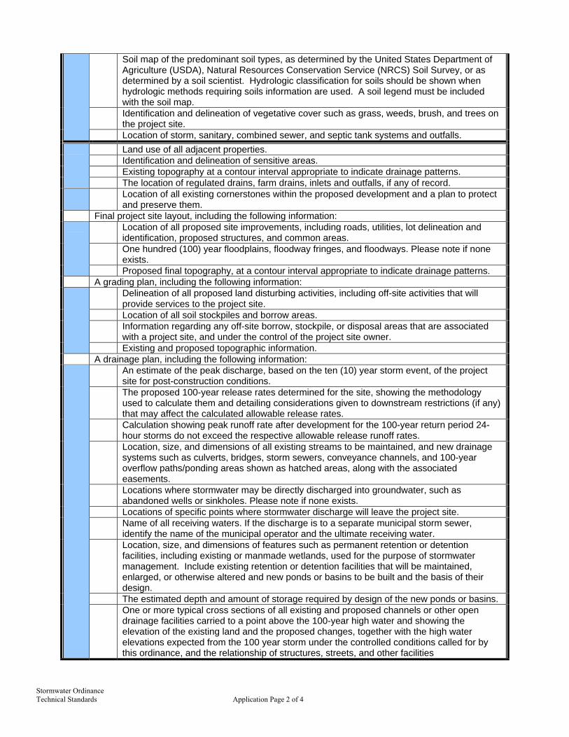
Stormwater Ordinance Technical Standards Application Page 2 of 4
Soil map of the predominant soil types, as determined by the United States Department of Agriculture (USDA), Natural Resources Conservation Service (NRCS) Soil Survey, or as determined by a soil scientist. Hydrologic classification for soils should be shown when hydrologic methods requiring soils information are used. A soil legend must be included with the soil map.
Identification and delineation of vegetative cover such as grass, weeds, brush, and trees on the project site.
Location of storm, sanitary, combined sewer, and septic tank systems and outfalls. Land use of all adjacent properties. Identification and delineation of sensitive areas. Existing topography at a contour interval appropriate to indicate drainage patterns.
The location of regulated drains, farm drains, inlets and outfalls, if any of record. Location of all existing cornerstones within the proposed development and a plan to protect
and preserve them. Final project site layout, including the following information:
Location of all proposed site improvements, including roads, utilities, lot delineation and identification, proposed structures, and common areas.
One hundred (100) year floodplains, floodway fringes, and floodways. Please note if none exists.
Proposed final topography, at a contour interval appropriate to indicate drainage patterns. A grading plan, including the following information:
Delineation of all proposed land disturbing activities, including off-site activities that will provide services to the project site.
Location of all soil stockpiles and borrow areas. Information regarding any off-site borrow, stockpile, or disposal areas that are associated
with a project site, and under the control of the project site owner.
Existing and proposed topographic information. A drainage plan, including the following information:
An estimate of the peak discharge, based on the ten (10) year storm event, of the project site for post-construction conditions.
The proposed 100-year release rates determined for the site, showing the methodology used to calculate them and detailing considerations given to downstream restrictions (if any) that may affect the calculated allowable release rates.
Calculation showing peak runoff rate after development for the 100-year return period 24-hour storms do not exceed the respective allowable release runoff rates.
Location, size, and dimensions of all existing streams to be maintained, and new drainage systems such as culverts, bridges, storm sewers, conveyance channels, and 100-year overflow paths/ponding areas shown as hatched areas, along with the associated easements.
Locations where stormwater may be directly discharged into groundwater, such as abandoned wells or sinkholes. Please note if none exists.
Locations of specific points where stormwater discharge will leave the project site. Name of all receiving waters. If the discharge is to a separate municipal storm sewer,
identify the name of the municipal operator and the ultimate receiving water. Location, size, and dimensions of features such as permanent retention or detention
facilities, including existing or manmade wetlands, used for the purpose of stormwater management. Include existing retention or detention facilities that will be maintained, enlarged, or otherwise altered and new ponds or basins to be built and the basis of their design.
The estimated depth and amount of storage required by design of the new ponds or basins.
One or more typical cross sections of all existing and proposed channels or other open drainage facilities carried to a point above the 100-year high water and showing the elevation of the existing land and the proposed changes, together with the high water elevations expected from the 100 year storm under the controlled conditions called for by this ordinance, and the relationship of structures, streets, and other facilities

Stormwater Ordinance Technical Standards Application Page 3 of 4
4. Stormwater Drainage Technical Report
A summary report, including the following information: The significant drainage problems associated with the project; The analysis procedure used to evaluate these problems and to propose solutions; Any assumptions or special conditions associated with the use of these procedures,
especially the hydrologic or hydraulic methods; The proposed design of the drainage control system; and
The results of the analysis of the proposed drainage control system showing that it does solve the project’s drainage problems. Any hydrologic or hydraulic calculations or modeling results must be adequately cited and described in the summary description. If hydrologic or hydraulic models are used, the input and output files for all necessary runs must be included in the appendices. A map showing any drainage area subdivisions used in the analysis must accompany the report.
A Hydrologic/Hydraulic Analysis, consistent with the methodologies and calculation included in the
[technical standards], and including the following information: A hydraulic report detailing existing and proposed drainage patterns on the subject site. The
report should include a description of present land use and proposed land use. Any off-site drainage entering the site should be addressed as well. This report should be comprehensive and detail all of the steps the engineer took during the design process.
All hydrologic and hydraulic computations should be included in the submittal. These calculations should include, but are not limited to: runoff curve numbers and runoff coefficients, runoff calculations, stage-discharge relationships, times-of-concentration and storage volumes.
Copies of all computer runs. These computer runs should include both the input and the outputs. Electronic copies of the computer runs with input files will expedite the review process and is required to be submitted.
A set of exhibits should be included showing the drainage sub-areas and a schematic detailing of how the computer models were set up.
A conclusion which summarizes the hydraulic design and details how this design satisfies this Ordinance.
5. Stormwater Pollution Prevention Plan for Construction Sites
Location, dimensions, detailed specifications, and construction details of all temporary and permanent stormwater quality measures.
Temporary stabilization plans and sequence of implementation. Permanent stabilization plans and sequence of implementation. Temporary and permanent stabilization plans shall include the following:
Specifications and application rates for soil amendments and seed mixtures. The type and application rate for anchored mulch.
Construction sequence describing the relationship between implementation of stormwater quality measures and stages of construction activities.
A typical erosion and sediment control plan for individual lot development. Self-monitoring program including plan and procedures. A description of potential pollutant sources associated with the construction activities, which may
reasonably be expected to add a significant amount of pollutants to stormwater discharges. Material handling and storage associated with construction activity shall meet the spill prevention
and spill response requirements in 327 IAC 2-6.1. Name, address, telephone number, and list of qualifications of the trained individual in charge of
the mandatory stormwater pollution prevention self-monitoring program for the project site.
6. Post-Construction Storm Water Pollution Prevention Plan
A description of potential pollutant sources from the proposed land use, which may reasonably be expected to add a significant amount of pollutants to stormwater discharges.
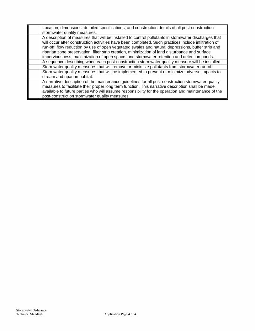
Stormwater Ordinance Technical Standards Application Page 4 of 4
Location, dimensions, detailed specifications, and construction details of all post-construction stormwater quality measures.
A description of measures that will be installed to control pollutants in stormwater discharges that will occur after construction activities have been completed. Such practices include infiltration of run-off, flow reduction by use of open vegetated swales and natural depressions, buffer strip and riparian zone preservation, filter strip creation, minimization of land disturbance and surface imperviousness, maximization of open space, and stormwater retention and detention ponds.
A sequence describing when each post-construction stormwater quality measure will be installed. Stormwater quality measures that will remove or minimize pollutants from stormwater run-off. Stormwater quality measures that will be implemented to prevent or minimize adverse impacts to
stream and riparian habitat. A narrative description of the maintenance guidelines for all post-construction stormwater quality
measures to facilitate their proper long term function. This narrative description shall be made available to future parties who will assume responsibility for the operation and maintenance of the post-construction stormwater quality measures.

Stormwater Ordinance Technical Standards N.O.I. Page 1 of 2
Indiana Department of Environmental Management
Notice of Intent (NOI) Storm Water Runoff Associated with Construction Activity
NPDES General Permit Rule 327 IAC 15-5 (Rule 5)
Submission of this Notice of Intent letter constitutes notice that the project site owner is applying for coverage under the National Pollutant Discharge Elimination System (NPDES) General Permit Rule for Storm Water Discharges Associated with Construction Activity. Permitted project site owners are required to comply with all terms and conditions of the General Permit Rule 327 IAC 15-5 (Rule 5).
Check the type of Submittal: Initial Amendment Renewal Extension Project Name and Location:
Project Permit #______________ Project Name:________________________________ County:_____________ Brief Description of Project Location: _____________________________________________________________ Latitude _____________________________ and Quarter _____________ Section ____________ Longitude ____________________________ Township____________ Range_____________
Does all or part of this project lie within the jurisdictional boundaries of a Municipal Separate Storm Sewer
System (MS4) as defined in 327 IAC 15-13? Yes No If yes, please name the MS4(s): _____________________________________________________________________________________________
Project Site Owner and Project Contact Information: Company Name (If Applicable): __________________________________________________________________ Project Site Owner’s Name (An Individual): ___________________________ Title/Position: _________________ Address: _____________________________________________________________________________________ Town: ______________________________________ State: ______________________ Zip: ________________ Phone: _______________ FAX: ________________ E-Mail Address (If Available): ________________________
Ownership Status (check one): Governmental Agency: Federal State Local
Non-Governmental: Public Private Other (Explain): _____________________________________ Contact Person: ____________________________ Affiliation with Project Site Owner: ____________________ Address (if different from above): ________________________________________________________________ Town: _______________________________________ State: ________________________ Zip: _______________ Phone: _______________ FAX: ________________ E-Mail Address (If Available): ________________________
Project Description:
Residential-Single Family Residential-Multi-Family Commercial Industrial Other__________________ Discharge Information:
Name of Receiving Water:______________________________________________________________________ (If applicable, name of municipal operator of storm sewer. Please note that even if a retention pond is present on the property, the name of the nearest possible receiving water is required).
Project Acreage:
Total Acreage: ________________ Acres Proposed Acreage to be Disturbed: ________________ Acres Total Impervious Surface Area (Estimated for Completed Project): ____________________ Square Feet
Timetable (Maximum of 5 Years):
Start Date: ________________ and Estimated End Date for all Land Disturbing Activity: _____________________
(Continued on Reverse Side)
Insert Local MS4 logo here

Stormwater Ordinance Technical Standards N.O.I. Page 2 of 2
Construction Plan Certification: By signing this Notice of Intent letter, I certify the following: A. The storm water quality measures included in the Construction Plan comply with the requirements of 327 IAC
15-5-6.5, 327 IAC 15-5-7, and 327 IAC 15-5-7.5; B. the storm water pollution prevention plan complies with all applicable federal, state, and local storm water
requirements; C. the measures required by section 7 and 7.5 of this rule will be implemented in accordance with the storm water
pollution prevention plan; D. if the projected land disturbance is One (1) acre or more, the applicable Soil and Water Conservation District or
other entity designated by the Department, has been sent a copy of the Construction Plan for review; E. storm water quality measures beyond those specified in the storm water pollution prevention plan will be
implemented during the life of the permit if necessary to comply with 327 IAC 15-5-7; and F. implementation of storm water quality measures will be inspected by trained individuals. In addition to this form, I have enclosed the Following:
Verification by the reviewing agency of acceptance of the Construction Plan. Proof of publication in a newspaper of general circulation in the affected area that notified the public that a
construction activity is to commence, including all required elements contained in 327 IAC 15-5-5 (9). $100 check or money order payable to the Indiana Department of Environmental Management. If the project lies
solely within the permitted jurisdiction of an MS4 and is regulated by the MS4 under 327 IAC 15-13 – a fee is not required with submittal of this Notice of Intent.
A permit issued under 327 IAC 15-5 is granted by the commissioner for a period of five (5) years from the date coverage commences. Once the five (5) year permit term duration is reached, a general permit issued under this rule will be considered expired, and, as necessary for construction activity continuation, a new Notice of Intent letter would need to be submitted ninety (90) days prior to the termination of coverage. Project Site Owner Responsibility Statement: By signing this Notice of Intent letter, I certify under penalty of law that this document and all attachments were prepared under my direction or supervision in accordance with a system designed to assure that qualified personnel properly gather and evaluate the information submitted. Based on my inquiry of the person or persons who manage the system, or those persons directly responsible for gathering the information, the information submitted is, to the best of my knowledge and belief, true, accurate, and complete. I am aware that there are significant penalties for submitting false information or violating the provisions of 327 IAC 15-5, including the possibility of fine and imprisonment for knowing violations. Printed Name of Project Owner__________________________________________________________ Signature of Project Owner ______________________________________ Date: ___________________ This Notice of Intent must be signed by an individual meeting the signatory requirements in 327 IAC 15-4-3(g) Mail this form to: Indiana Department of Environmental Management
Office of Water Quality, Storm Water (Rule 5) Desk 100 North Senate Avenue, P.O. Box 6015 Indianapolis, IN 46206-6015 327 IAC 15-5-6 (a) also requires a copy of the completed Notice of Intent letter be submitted to the local Soil and Water Conservation District or other entity designated by the Department, where the land disturbing activity is to occur.
Questions regarding the development of the Construction Plan and/or field implementation of 327 IAC 15-5 may be directed to your local Soil and Water Conservation District office or the Department of Natural Resources at 317-233-3870. Questions regarding the Notice of Intent may be directed to the Rule 5 contact person at 317/233-1864 or 800/451-6027 ext 31864. State Form 47487 (R3 / 12-03)

Date: _______________________________ Project: _______________________________ Inspected by: _______________________________
Type of Inspection: Scheduled Weekly Rain Event
Stormwater Ordinance Technical Standards Const. Insp. Log Page 1 of 1
Insert Local Logo Here
CONSTRUCTION SITE INSPECTION AND MAINTENANCE LOG (To be Completed by Property Owner or Agent)
All stormwater pollution prevention BMPs shall be inspected and maintained as needed to ensure continued performance of their intended function during construction and shall continue until the entire site has been stabilized and a Notice of Termination has been issued. An inspection of the project site must be completed by the end of the next business day following each measurable storm event. If there are no measurable storm events within a given week, the site should be monitored at least once in that week. Maintenance and repair shall be conducted in accordance with the accepted site plans. This log shall be kept as a permanent record and must be made available to Town of Merrillville Town Engineer, in an organized fashion, within forty-eight (48) hours upon request.
Yes No N/A 1. Are all sediment control barriers, inlet protection and silt fences in place and functioning
properly? 2. Are all erodible slopes protected from erosion through the implementation of acceptable
soil stabilization practices? 3. Are all dewatering structures functioning properly? 4. Are all discharge points free of any noticeable pollutant discharges? 5. Are all discharge points free of any noticeable erosion or sediment transport? 6. Are designated equipment washout areas properly sited, clearly marked, and being
utilized? 7. Are construction staging and parking areas restricted to areas designated as such on the
plans? 8. Are temporary soil stockpiles in approved areas and properly protected? 9. Are construction entrances properly installed and being used and maintained? 10. Are “Do Not Disturb” areas designated on plan sheets clearly marked on-site and avoided? 11. Are public roads at intersections with site access roads being kept clear of sediment,
debris, and mud? 12. Is spill response equipment on-site, logically located, and easily accessed in an
emergency? 13. Are emergency response procedures and contact information clearly posted? 14. Is solid waste properly contained? 15. Is a stable access provided to the solid waste storage and pick-up area? 16. Are hazardous materials, waste or otherwise, being properly handled and stored? 17. Have previously recommended corrective actions been implemented? If you answered “no” to any of the above questions, describe any corrective action which must be taken to remedy the problem and when the corrective actions are to be completed.

Stormwater Ordinance Technical Standards Cert. of Comp. Page 1 of 1
Certification of Completion & Compliance
CERTIFICATE OF COMPLETION & COMPLIANCE
Address of premises on which land alteration was accomplished:____________________________________ ________________________________________________________________________________________ ________________________________________________________________________________________ Inspection Date(s):__________________________ Permit Number:________________________________ Relative to plans prepared by:_________________________ on__________________________________
(date) I hereby certify that:
1. I am familiar with drainage requirements applicable to such land alteration (as set forth in the
Stormwater Management Ordinance of Town of Merrillville); and
2. I (or a person under my direct supervision) have personally inspected the completed work and examined the drainage permit and its conditions, as-built plans, and final drainage calculations consistent with as-built conditions performed pursuant to the above referenced drainage permit; and
3. To the best of my knowledge, information, and belief, such land alteration has been performed
and completed in conformity with all such drainage requirements, except ______________ __________________________________________________________________________ __________________________________________________________________________
Signature: _____________________________ Date: ___________________________ Typed or Printed Name: _____________________________ Phone: (___)_____________________ (SEAL) Business Address: _______________________________
_______________________________ _______________________________ _______________________________
TOWN ENGINEER ENGINEER
(circle one) Indiana Registration No._______________________
Insert Local Logo Here

Stormwater Ordinance Technical Standards N.O.T. Page 1 of 2
RULE 5 – Notice of Termination (NOT) Storm Water Runoff Associated with Construction Activity NPDES General Permit Rule 327 IAC 15-5 (Rule 5) State Form 51514 (R / 1-04) INDIANA DEPARTMENT OF ENVIRONMENTAL MANAGEMENT
NOTE: This Notice of Termination must be signed by an individual meeting the signatory requirements in 327 IAC 15-4-3(g).
Please submit the completed Notice of Termination form to the SWCD, DNR-DSC, or other Entity Designated by the Department as the reviewing agency. The request for termination will be reviewed for concurrence and either returned to the Project Site Owner or forwarded to the IDEM.
Submission of this Notice of Termination letter constitutes notice to the Commissioner that the project site owner is applying for Termination of Coverage under the National Pollutant Discharge Elimination System (NPDES) General Permit Rule for Storm Water Discharges Associated with Construction Activity. Project Name and Location: Permit Number: ________________ Project Name: ________________________________________________ County: _________________________ Company Name (If Applicable): __________________________________________________________________ Project Site Owner’s Name (An Individual): ________________________________________________________ Address: _____________________________________________________________________________________ Town: ___________________________________________ State: ___________________ Zip: ________________ Phone: ________________ FAX: _______________ E-Mail Address (If Available): _________________________
This Notice of Termination is Being Submitted for the Following:
Select one of the three Options that apply to Permit Termination by checking the appropriate box, complete all information associated with that option, and complete the “Project Site Owner Responsibility Statement”.
Option # 1
Certification for Change of Ownership: (Does not Apply to the Sale of Individual lots within the Permitted Acreage; only the Sale of the Entire Project Site as Originally Permitted)
By Signing this Notice of Termination, I Certify the Following: A. The project was sold; I am no longer the project site owner as was designated in my Notice of Intent. The new
owner of the project site is: Company Name (If Applicable): ___________________________________________________________ Project Site Owner’s Name (An Individual): _________________________________________________ Address: _____________________________________________________________________________ Town: _________________________________ State: ______________________ Zip: ________________ Phone: ______________ FAX: ______________ E-Mail Address (If Available): ____________________
B. I have notified the new Project Site Owner of his/her responsibilities to comply with 327 IAC 15-5 and the requirements associated with the rule including filing a new Notice of Intent.
For questions regarding this form, contact: IDEM – Rule 5 Coordinator 100 North Senate Avenue, Rm 1255 P.O. Box 6015 Indianapolis, IN 46206-6015 Phone: (317) 233-1864 or
(800) 451-6027, ext. 31864 (within Indiana) Web Access: http://www.in.gov/idem/water/npdes/permits/wetwthr/storm/rule5.html
Insert Local Logo Here

Stormwater Ordinance Technical Standards N.O.T. Page 2 of 2
Option # 2 Certification for Termination of Construction Activities:
By Signing this Notice of Termination, I Certify the Following:
A. All land disturbing activities, including construction on all building lots have been completed and the entire site has been stabilized;
B. No future land disturbing activities will occur on this project site; C. All temporary erosion and sediment control measures have been removed; and D. A copy of this notice has been sent to the appropriate SWCD or other designated entity.
Option # 3 Notice of Termination to Obtain Early Release from Compliance with 327 IAC 15-5
By Signing this Notice of Termination, I Certify the Following: A. The remaining, undeveloped acreage does not exceed five (5) acres, with contiguous areas not to exceed one (1) acre. B. A map of the project site, clearly identifying all remaining undeveloped lots, is attached to this letter. The map must be
accompanied by a list of names and addresses of individual lot owners or individual lot operators of all undeveloped lots. C. All public and common improvements, including infrastructure, have been completed and permanently stabilized and
have been transferred to the appropriate local entity. D. The remaining acreage does not pose a significant threat to the integrity of the infrastructure, adjacent properties, or
water quality. E. All permanent storm water quality measures have been implemented and are operational. Upon Written Notification of the Department the Project Site Owner Certifies that he/she will Notify: A. All current individual lot owners and all subsequent individual lot owners of the remaining undeveloped acreage and
acreage with construction activity that they are responsible for complying with section 7.5 of 327 IAC 15-5 (the remaining individual lot owners do not need to submit a Notice of Intent letter or Notice of Termination letter); and
B. The individual lot owners of the requirements to install and maintain appropriate measures to prevent sediment from leaving the individual building lot and maintain all erosion and sediment control measures that are to remain on-site as part of the construction plan.
Project Site Owner Responsibility Statement: By signing this Notice of Termination letter, I certify under penalty of law that this document and all attachments were prepared under my direction or supervision in accordance with a system designed to assure that qualified personnel properly gather and evaluate the information submitted. Based on my inquiry of the person or persons who manage the system, or those persons directly responsible for gathering the information, the information submitted is, to the best of my knowledge and belief, true, accurate, and complete. I am aware that there are significant penalties for submitting false information, including the possibility of fine and imprisonment for knowing violations. Printed Name of Project Site Owner: ________________________________________________________________________ Signature of Project Site Owner: _________________________________________________ Date: _____________________ This Notice of Termination must be signed by an individual meeting the signatory requirements in 327 IAC 15-4-3(g). Please submit the completed Notice of Termination form to the SWCD, DNR-DSC, or other Entity Designated by the Department as the reviewing agency. The request for termination will be reviewed for concurrence and either returned to the Project Site Owner or forwarded to the IDEM.
For Agency Use Only
Accepted: The site referenced above has been inspected and it has been determined that the request to terminate this project is compliant with the requirements of 327 IAC 15-5-8. This form will be forwarded to the IDEM for final approval. Upon written notification by the IDEM, the Project Site Owner’s termination for coverage under 327 IAC 15-5 shall be considered approved.
Denied: The site referenced above has been inspected and it has been determined that the request to terminate this project is NOT compliant with the requirements of 327 IAC 15-5-8. Continue to implement the Stormwater Pollution Prevention Plan and take appropriate measures to minimize the discharge of pollutants.
____________________________ ____________________________ ________________________________ _________
Signature Printed Name Agency Date
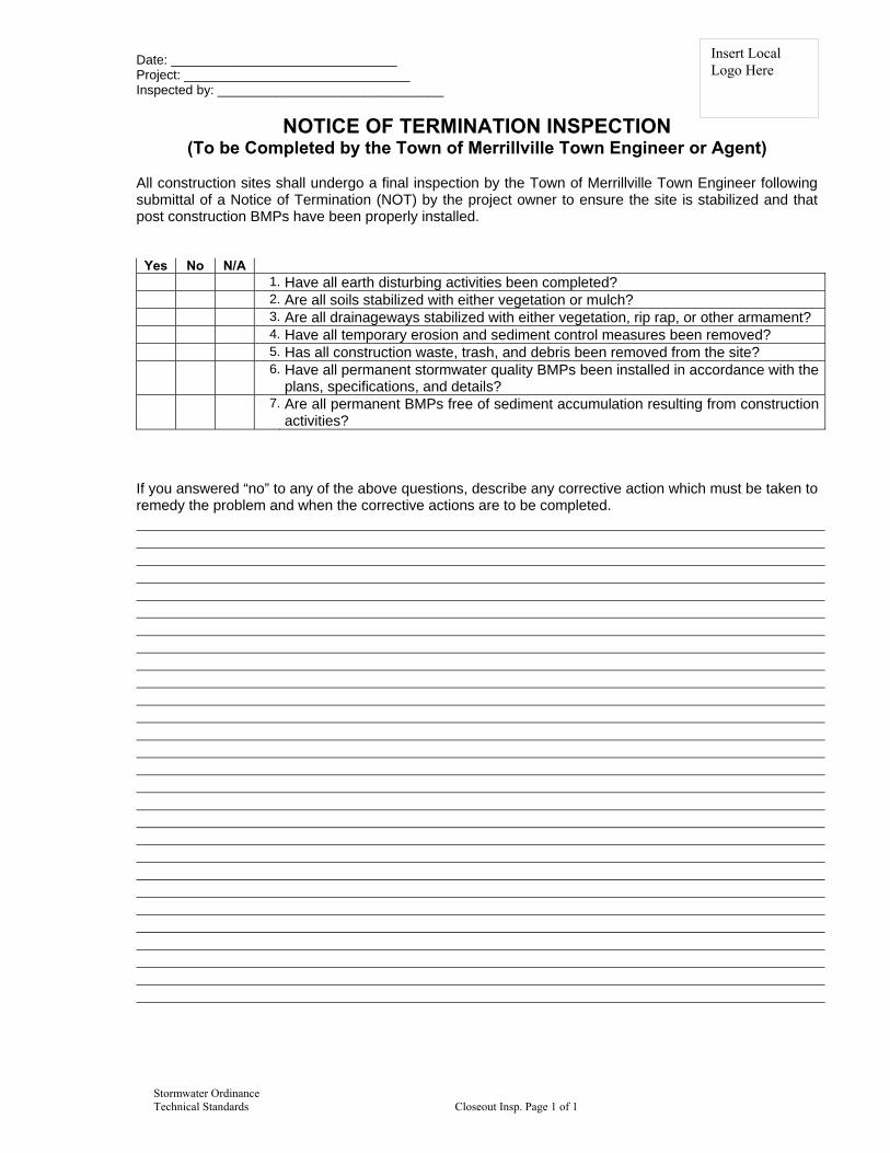
Date: _______________________________ Project: _______________________________ Inspected by: _______________________________
Stormwater Ordinance Technical Standards Closeout Insp. Page 1 of 1
Insert Local Logo Here
NOTICE OF TERMINATION INSPECTION (To be Completed by the Town of Merrillville Town Engineer or Agent)
All construction sites shall undergo a final inspection by the Town of Merrillville Town Engineer following submittal of a Notice of Termination (NOT) by the project owner to ensure the site is stabilized and that post construction BMPs have been properly installed.
Yes No N/A 1. Have all earth disturbing activities been completed? 2. Are all soils stabilized with either vegetation or mulch? 3. Are all drainageways stabilized with either vegetation, rip rap, or other armament? 4. Have all temporary erosion and sediment control measures been removed? 5. Has all construction waste, trash, and debris been removed from the site? 6. Have all permanent stormwater quality BMPs been installed in accordance with the
plans, specifications, and details? 7. Are all permanent BMPs free of sediment accumulation resulting from construction
activities? If you answered “no” to any of the above questions, describe any corrective action which must be taken to remedy the problem and when the corrective actions are to be completed.

Stormwater Ordinance Technical Standards Ind. Lot E&SC Cert. 1 of 1

Post-Construction BMP Inspection Checklist Bioretention
Stormwater Ordinance Technical Standards Biofilter and Buffer O&M 1 of 2
Bioretention Operation, Maintenance, and Management Inspection Checklist
Project: ___________________________________________________________________________________
Location: ___________________________________________________________________________________
Date: _________________________________________ Time: ____________________________
Inspector: _________________________________________ Title: ____________________________
Signature: ____________________________________________________
Maintenance Item Satisfactory/ Unsatisfactory Comments
1. Debris Cleanout
Bioretention and contributing areas clean of debris (litter, branches, etc.)
No dumping of yard wastes into BMP
2. Vegetation
Plant height not less than design water depth but not greater than 6 inches
Observed plant types consistent with accepted plans
Plants covering greater than 85% of total BMP surface area
Plant community appears thick and healthy
No evidence of erosion
3. Sediment Deposits/Accumulation
No evidence of sediment buildup around check dams or energy dissipaters.
Sumps are not more than 50% full of sediment
Sediment is not >20% of BMP design depth.

Post-Construction BMP Inspection Checklist Bioretention
Stormwater Ordinance Technical Standards Biofilter and Buffer O&M 2 of 2
4. Filter Bed
Dewaters between storms
Filter bed is not blocked or filled inappropriately.
5. Outlet/Overflow Spillway
Good Condition, no need for repair
No evidence of erosion or downstream scour.
Outlets are free of blockages.
Actions to be Taken:_____________________________________________________________________________

Post-Construction BMP Inspection Checklist Wetland
Stormwater Ordinance Technical Standards Wetland O&M 1 of 2
Wetland Operation, Maintenance, and Management Inspection Checklist
Project: ___________________________________________________________________________________
Location: ___________________________________________________________________________________
Date: _________________________________________ Time: ____________________________
Inspector: _________________________________________ Title: ____________________________
Signature: ____________________________________________________
Maintenance Item Satisfactory/ Unsatisfactory Comments
1. Embankment and Emergency Spillway
Healthy vegetation with at least 85% ground cover.
No signs of erosion on embankment.
No animal burrows.
Embankment is free of cracking, bulging, or sliding.
Embankment is free of woody vegetation.
Embankment is free of leaks or seeps
Emergency spillway is clear of obstructions.
2. Riser and Principal Spillway
Low flow outlet free of obstruction.
Trash rack is not blocked or damaged.
Riser is free of excessive sediment buildup
Outlet pipe is in good condition.

Post-Construction BMP Inspection Checklist Wetland
Stormwater Ordinance Technical Standards Wetland O&M 2 of 2
Control valve is operational
Outfall channels are stable and free of scouring.
3. Wetland Plants covering greater than 85% of total wetland surface area (excluding open water areas)
Observed plant types consistent with accepted plans
No evidence of excessive sediment accumulation in wetland area
Water depths consistent with accepted plans
No evidence of erosion on banks.
Wetland areas clean of debris (litter, branches, etc.)
No evidence of dumping of yard wastes into BMP
4. Forebay
Sediment is being collected by forebay(s)
Forebay is not in need of cleanout (less than 50% full)
Actions to be Taken:_____________________________________________________________________________

Post-Construction BMP Inspection Checklist Infiltration Trench
Stormwater Ordinance Technical Standards Inf. Trench O&M 1 of 2
Infiltration Trench Operation, Maintenance, and Management Inspection Checklist
Project: ___________________________________________________________________________________
Location: ___________________________________________________________________________________
Date: _________________________________________ Time: ____________________________
Inspector: _________________________________________ Title: ____________________________
Signature: ____________________________________________________
Maintenance Item Satisfactory/ Unsatisfactory Comments
1. Debris Cleanout
Trench surface clear of debris
Inflow pipes clear of debris
Overflow spillway clear of debris
Inlet area clear of debris
2. Sediment Traps or Forebays
Obviously trapping sediment
Greater than 50% of storage volume remaining
3. Trench
Trench dewaters between storms
No evidence of sedimentation in trench
Sediment accumulation doesn’t yet require cleanout
4. Inlets
Good condition
No evidence of erosion

Post-Construction BMP Inspection Checklist Infiltration Trench
Stormwater Ordinance Technical Standards Inf. Trench O&M 2 of 2
Maintenance Item Satisfactory/ Unsatisfactory Comments
5. Outlet/Overflow Spillway
Good condition, no need for repair
No evidence of erosion
6. Aggregate Repairs
Surface of aggregate clean
Top layer of stone does not need replacement
Trench does not need rehabilitation
Actions to be Taken:_____________________________________________________________________________

Post-Construction BMP Inspection Checklist Infiltration Basin
Stormwater Ordinance Technical Standards Inf. Basin O&M 1 of 2 July 2004
Infiltration Basin Operation, Maintenance, and Management Inspection Checklist
Project: ___________________________________________________________________________________
Location: ___________________________________________________________________________________
Date: _________________________________________ Time: ____________________________
Inspector: _________________________________________ Title: ____________________________
Signature: ____________________________________________________
Maintenance Item Satisfactory/ Unsatisfactory Comments
1. Debris Cleanout
Basin bottom clear of debris
Inlet clear of debris
Outlet clear of debris
Emergency spillway clear of debris
2. Sediment Traps or Forebays
Obviously trapping sediment
Greater than 50% of storage volume remaining
3. Vegetation
Mowing done when needed
No evidence of erosion
4. Dewatering
Basin dewatered between storms

Post-Construction BMP Inspection Checklist Infiltration Basin
Stormwater Ordinance Technical Standards Inf. Basin O&M 2 of 2 July 2004
Maintenance Item Satisfactory/ Unsatisfactory Comments
5. Sediment Cleanout of Basin
No evidence of sedimentation
Sediment accumulation does not yet require cleanout
6. Inlets
Good condition
No evidence of erosion
7. Outlets/Overflow Spillway
Good condition, no need for repair
No evidence of erosion
8. Structural Repairs
Embankment in good repair
Side slopes are stable
No evidence of erosion
9. Fences/Access Repairs
Fences in good condition
No damage which would allow undesirable entry
Lock and gate function adequate
Access point in good condition
Actions to be Taken:_____________________________________________________________________________

Post-Construction BMP Inspection Checklist Media Filtration
Stormwater Ordinance Technical Standards Media Filter O&M 1 of 2
Media Filtration Operation, Maintenance, and Management Inspection Checklist
Project: ___________________________________________________________________________________
Location: ___________________________________________________________________________________
Date: _________________________________________ Time: ____________________________
Inspector: _________________________________________ Title: ____________________________
Signature: ____________________________________________________
Maintenance Item Satisfactory/ Unsatisfactory Comments
1. Debris Cleanout
Contributing areas clean of debris
Filtration facility clean of debris
Inlet and outlets clear of debris
2. Oil and Grease
No evidence of filter surface clogging
Activities in drainage area minimize oil and grease entry
3. Vegetation
Contributing drainage area stabilized
No evidence of erosion
Area mowed and clippings removed
4. Water Retention Where Required
Water holding chambers at normal pool
No evidence of leakage
Actions to be Taken:_____________________________________________________________________________

Post-Construction BMP Inspection Checklist Media Filtration
Stormwater Ordinance Technical Standards Media Filter O&M 2 of 2

Post-Construction BMP Inspection Checklist Filter Strip
Stormwater Ordinance Technical Standards Filter Strip O&M 1 of 2
Filter Strip Operation, Maintenance, and Management Inspection Checklist
Project: ___________________________________________________________________________________
Location: ___________________________________________________________________________________
Date: _________________________________________ Time: ____________________________
Inspector: _________________________________________ Title: ____________________________
Signature: ____________________________________________________
Maintenance Item Satisfactory/ Unsatisfactory Comments
1. Vegetation
Observed plant types consistent with accepted plans
Vegetation is healthy
Plants covering greater than 85% of total BMP surface area
Grass height not more than 6 inches
No evidence of concentrated flows
No evidence of erosion
2. Level Spreader
Lip of spreader showing no signs of erosion
Sediment noted in spreader?
Actions to be Taken:_____________________________________________________________________________

Post-Construction BMP Inspection Checklist Vegetated Swale
Stormwater Ordinance Technical Standards Veg. Swale O&M 2 of 2
Vegetated Swale Operation, Maintenance, and Management Inspection Checklist
Project: ___________________________________________________________________________________
Location: ___________________________________________________________________________________
Date: _________________________________________ Time: ____________________________
Inspector: _________________________________________ Title: ____________________________
Signature: ____________________________________________________
Maintenance Item Satisfactory/ Unsatisfactory Comments
1. Debris Cleanout
Contributing drainage areas free from debris
2. Vegetation
Mowing performed when needed
No evidence of erosion
3. Check Dams or Energy Dissipaters
No evidence of flow going around structure
No evidence of erosion at the downstream toe
Soil permeability
4. Sediment Forebay
Sediment cleanout not needed (clean out when 50% full)
Actions to be Taken:_____________________________________________________________________________

Post-Construction BMP Inspection Checklist Detention pond
Stormwater Ordinance Technical Standards Detention Pond O&M 1 of 2
Detention Pond Operation, Maintenance, and Management Inspection Checklist
Project: ___________________________________________________________________________________
Location: ___________________________________________________________________________________
Date: _________________________________________ Time: ____________________________
Inspector: _________________________________________ Title: ____________________________
Signature: ____________________________________________________
Maintenance Item Satisfactory/ Unsatisfactory Comments
1. Embankment and emergency spillway
Healthy vegetation with at least 85% ground cover.
No signs of erosion on embankment.
No animal burrows.
Embankment is free of cracking, bulging, or sliding.
Embankment is free of woody vegetation.
Embankment is free of leaks or seeps
Emergency spillway is clear of obstructions.
Vertical/horizontal alignment of top of dam “As-Built”
2. Riser and principal spillway
Low flow outlet free of obstruction.
Trash rack is not blocked or damaged.
Riser is free of excessive sediment buildup
Outlet pipe is in good condition.
Control valve is operational
Outfall channels are stable and free of scouring.

Post-Construction BMP Inspection Checklist Detention pond
Stormwater Ordinance Technical Standards Detention Pond O&M 2 of 2
Maintenance Item Satisfactory/ Unsatisfactory Comments
3. Permanent Pool (Wet Ponds)
No Evidence of undesirable vegetation
No accumulation of floating or floatable debris
No evidence of shoreline scour or erosion
4. Sediment Forebays
Sediment is being collected by forebay(s)
Forebay is not in need of cleanout (less than 50% full)
5. Dry Pond Areas
Healthy vegetation with at least 85% ground cover.
No undesirable woody vegetation
Low flow channels clear of obstructions
No evidence of sediment and/or trash accumulation
6. Condition of Outfall into Ponds
No riprap failures
No evidence of slope erosion or scouring
Storm drain pipes are in good condition, with no evidence of non-stormwater discharges
Endwalls/Headwalls are in good condition

Stormwater Ordinance Technical Standards Appendix C
APPENDIX C
CONSTRUCTION BMPs

Stormwater Ordinance Technical Standards CN-101-1
BMP CN – 101 CONSTRUCTION SEQUENCING DESCRIPTION The construction sequence schedule is an orderly listing of all major land-disturbing activities together with the necessary erosion and sedimentation control measures planned for the project. This type of schedule guides the contractor on work to be done before other work is started so that serious erosion and sedimentation problems can be avoided. Sequencing a construction project reduces the amount and duration of soil exposed to erosion by wind, rain, runoff, and vehicle tracking. ADVANTAGE 1. Following a specified work schedule that coordinates the timing of land-disturbing
activities and the installation of control measures is perhaps the most cost-effective way of controlling erosion during construction. The removal of surface ground cover leaves a site vulnerable to accelerated erosion. Construction procedures that limit land clearing, provide timely installation of erosion and sedimentation controls, and restore protective cover quickly can significantly reduce the erosion potential of a site.
DESIGN CRITERIA 1. Avoid rainy periods. 2. Schedule projects to disturb only small portions of the site at any one time.
Complete grading as soon as possible. Immediately stabilize the disturbed portion before grading the next portion. Practice staged seeding in order to revegetate cut and fill slopes as the work progresses.
REFERENCE Town of Tacoma, Surface Water Management Manual, 2003 or later
BMP CN – 101 CONSTRUCTION SEQUENCING
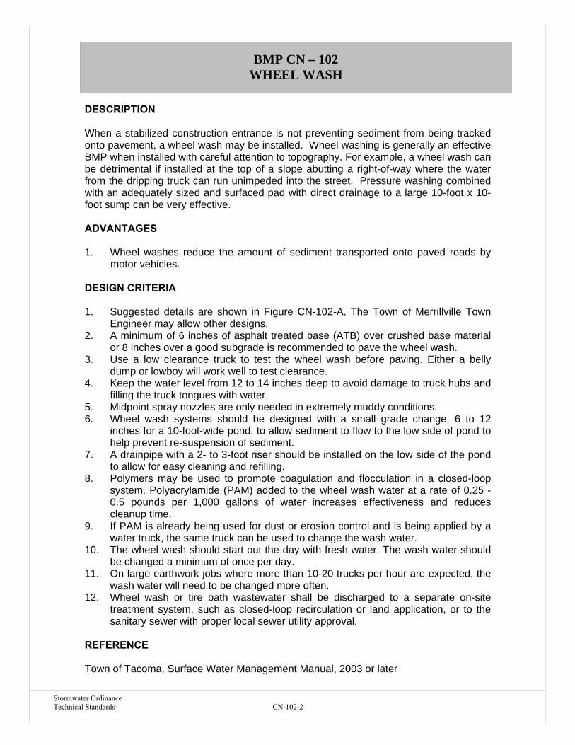
Stormwater Ordinance Technical Standards CN-102-2
BMP CN – 102 WHEEL WASH DESCRIPTION When a stabilized construction entrance is not preventing sediment from being tracked onto pavement, a wheel wash may be installed. Wheel washing is generally an effective BMP when installed with careful attention to topography. For example, a wheel wash can be detrimental if installed at the top of a slope abutting a right-of-way where the water from the dripping truck can run unimpeded into the street. Pressure washing combined with an adequately sized and surfaced pad with direct drainage to a large 10-foot x 10-foot sump can be very effective. ADVANTAGES 1. Wheel washes reduce the amount of sediment transported onto paved roads by
motor vehicles. DESIGN CRITERIA 1. Suggested details are shown in Figure CN-102-A. The Town of Merrillville Town
Engineer may allow other designs. 2. A minimum of 6 inches of asphalt treated base (ATB) over crushed base material
or 8 inches over a good subgrade is recommended to pave the wheel wash. 3. Use a low clearance truck to test the wheel wash before paving. Either a belly
dump or lowboy will work well to test clearance. 4. Keep the water level from 12 to 14 inches deep to avoid damage to truck hubs and
filling the truck tongues with water. 5. Midpoint spray nozzles are only needed in extremely muddy conditions. 6. Wheel wash systems should be designed with a small grade change, 6 to 12
inches for a 10-foot-wide pond, to allow sediment to flow to the low side of pond to help prevent re-suspension of sediment.
7. A drainpipe with a 2- to 3-foot riser should be installed on the low side of the pond to allow for easy cleaning and refilling.
8. Polymers may be used to promote coagulation and flocculation in a closed-loop system. Polyacrylamide (PAM) added to the wheel wash water at a rate of 0.25 - 0.5 pounds per 1,000 gallons of water increases effectiveness and reduces cleanup time.
9. If PAM is already being used for dust or erosion control and is being applied by a water truck, the same truck can be used to change the wash water.
10. The wheel wash should start out the day with fresh water. The wash water should be changed a minimum of once per day.
11. On large earthwork jobs where more than 10-20 trucks per hour are expected, the wash water will need to be changed more often.
12. Wheel wash or tire bath wastewater shall be discharged to a separate on-site treatment system, such as closed-loop recirculation or land application, or to the sanitary sewer with proper local sewer utility approval.
REFERENCE Town of Tacoma, Surface Water Management Manual, 2003 or later
BMP CN – 102 WHEEL WASH

Stormwater Ordinance Technical Standards CN-102-2
Figure CN-102-A
Section A-A
NTS
1
6
32
8
54
79

Stormwater Ordinance Technical Standards CN-103-1
BMP CN – 103 DEWATERING STRUCTURE DESCRIPTION Water which is pumped from a construction site usually contains a large amount of sediment. A dewatering structure is designed to remove the sediment before water is released off-site. This practice includes several types of dewatering structures which have different applications dependent upon site conditions and types of operation. Other innovative techniques for accomplishing the same purpose are encouraged, but only after specific plans and details are submitted to and approved by the Town of Merrillville Town Engineer. DESIGN CRITERIA 1. A dewatering structure must be sized (and operated) to allow pumped water to flow
through the filtering device without overtopping the structure. 2. Material from any required excavation shall be stored in an area and protected in a
manner that will prevent sediments from eroding and moving off-site. 3. An excavated basin (applicable to “Straw Bale/Silt Fence Pit”) may be lined with
filter fabric to help reduce scour and to prevent the inclusion of soil from within the structure.
4. Design criteria more specific to each particular dewatering device can be found in Figures CN-103-A through CN-103-C.
5. A dewatering structure may not be needed if there is a well-stabilized, vegetated area onsite to which water may be discharged. The area must be stabilized so that it can filter sediment and at the same time withstand the velocity of the discharged water without eroding. A minimum filtering length of 75 feet must be available in order for such a method to be feasible.
6. The filtering devices must be inspected frequently and repaired or replaced once the sediment build-up prevents the structure from functioning as designed.
7. The accumulated sediment which is removed from a dewatering device must be spread on-site and stabilized or disposed of at an approved disposal site as per approved plan.
Portable Sediment Tank (see Figure CN103-A) • The structure may be constructed with steel drums, sturdy wood or other
material suitable for handling the pressure exerted by the volume of water. • Sediment tanks will have a minimum depth of 2 ft. • The sediment tank shall be located for easy clean-out and disposal of the
trapped sediment and to minimize the interference with construction activities. • The following formula shall be used to determine the storage volume of the
sediment tank: Pump discharge (gallons/min.) x 16 = cubic feet of storage required
• Once the water level nears the top of the tank, the pump must be shut off while the tank drains and additional capacity is made available.
• The tank shall be designed to allow for emergency flow over top of the tank. Clean-out of the tank is required once one-third of the original capacity is
BMP CN – 103 DEWATERING STRUCTURE
Stormwater Ordinance Technical Standards CN-103-2
depleted due to sediment accumulation. The tank shall be clearly marked showing the clean-out point.
Filter Box (see Figure CN-103-B)
• The box selected should be made of steel, sturdy wood or other materials suitable to handle the pressure requirements imposed by the volume of water. Normally readily available 55 gallon drums welded top to bottom will suffice in most cases.
• Bottom of the box shall be made porous by drilling holes (or some other method).
• Coarse aggregate shall be placed over the holes at a minimum depth of 12 inches, metal “hardware” cloth may need to be placed between the aggregate and the holes if holes are drilled larger than the majority of the stone.
• As a result of the fast rate of flow of sediment-laden water through the aggregate, the effluent must be directed over a well-vegetated strip of at least 50 feet after Ieaving the base of the filter box.
• The box shall be sized as follows: Pump discharge (gallons/min.) x 16 = cubic feet of storage required
• Once the water level nears the top of the box, the pump must be shut off while the box drains and additional capacity is made available.
• The box shall be designed/constructed to allow for emergency flow over the top of this box.
• Clean-out of the box is required once one-third of the original capacity is depleted due to sediment accumulation. The tank shall be clearly marked showing the clean-out point.
• If the stone filter does become clogged with sediment so that it no longer adequately performs its function, the stones must be pulled away from the inlet, cleaned and replaced.
• Using a filter box only allows for minimal settling time for sediment particles; therefore, it should only be used when site conditions restrict the use of the other methods.
Straw Bale/Silt Fence Pit (see Figure CN-103-C) • Measure shall consist of straw bales, silt fence, a stone outlet (a combination
of riprap and aggregate) and a wet storage pit oriented as shown in Figure CN-103-C.
• The structure must have a capacity which is dictated by the following formula: Pump discharge (gallons/min.) x 16 = cubic feet of storage required
• In calculating the capacity, one should include the volume available from the floor of the excavation to the crest of the stone weir.
• In any case, the excavated area should be a minimum of 3 feet below the base of the perimeter measures (straw bales or silt fence).
• The perimeter measures must be installed as per the guidelines found in BMP-4, STRAW BALE BARRIER and BMP-5, SILT FENCE.
• Once the water level nears the crest of the stone weir (emergency overflow), the pump must be shut off while the structure drains down to the elevation of the wet storage.
• The wet storage pit may be dewatered only after a minimum of 6 hours of sediment settling time. This effluent should be pumped across a well vegetated area or through a silt fence prior to entering a watercourse.

Stormwater Ordinance Technical Standards CN-103-3
• Once the wet storage area becomes filled to one-half of the, excavated depth, accumulated sediment shall be removed and properly disposed of.
• Once the device has been removed, ground contours will be returned to original condition.
REFERENCE United States Army Corps of Engineers, Handbook for the Preparation of Storm Water Pollution Prevention Plans for Construction Activities, 1997 or later

Stormwater Ordinance Technical Standards CN-103-4
Figure CN-103-A Portable Sediment Tank
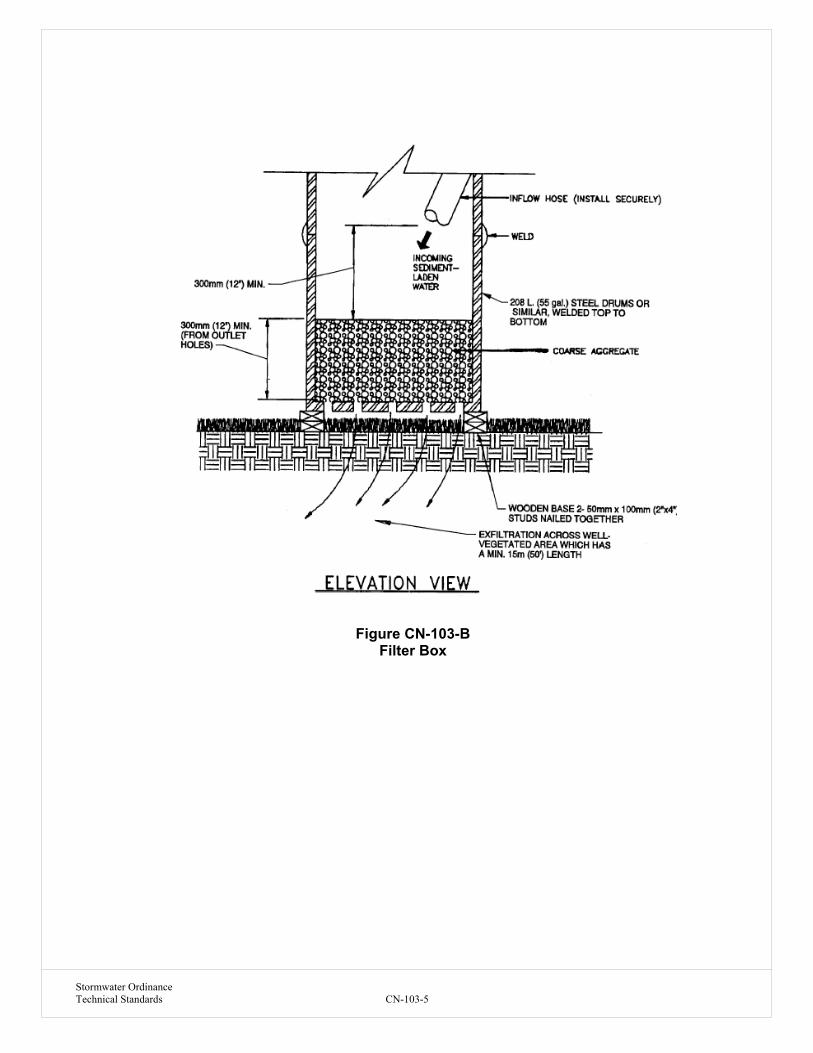
Stormwater Ordinance Technical Standards CN-103-5
Figure CN-103-B
Filter Box

Stormwater Ordinance Technical Standards CN-103-6
Figure CN-103-C
Straw Bale/Silt Fence Pit

Stormwater Ordinance Technical Standards CN-104-1
BMP CN – 104 SPILL PREVENTION AND CONTROL DESCRIPTION These procedures and practices are implemented to prevent and control spills in a manner that minimizes or prevents the discharge of spilled material to the drainage system or watercourses. This best management practice (BMP) applies to all construction projects. Spill control procedures are implemented anytime chemicals and/or hazardous substances are stored. Substances may include, but are not limited to: • Soil stabilizers/binders • Dust Palliatives • Herbicides • Growth inhibitors • Fertilizers • Deicing/anti-icing chemicals • Fuels • Lubricants • Other petroleum distillates To the extent that the work can be accomplished safely, spills of oil, petroleum products, sanitary and septic wastes, and substances listed under 40 CFR parts 110, 117, and 302, and shall be contained and cleaned up immediately. LIMITATIONS 1. This BMP only applies to spills caused by the contractor. 2. Procedures and practices presented in this BMP are general. Contractor shall
identify appropriate practices for the specific materials used or stored on-site in advance of their arrival at the site.
DESIGN CRITERIA 1. To the extent that it doesn’t compromise clean up activities, spills shall be covered
and protected from stormwater runoff during rainfall. 2. Spills shall not be buried or washed with water. 3. Used clean up materials, contaminated materials, and recovered spill material that
is no longer suitable for the intended purpose shall be stored and disposed of in conformance with BMP CN-106: Hazardous Waste Management.
4. Water used for cleaning and decontamination shall not be allowed to enter storm drains or watercourses and shall be collected and disposed of in accordance with BMP CN-106: Hazardous Waste Management.
5. Water overflow or minor water spillage shall be contained and shall not be allowed to discharge into drainage facilities or watercourses.
BMP CN – 104 SPILL PREVENTION AND CONTROL
Stormwater Ordinance Technical Standards CN-104-2
6. Proper storage, clean-up and spill reporting instruction for hazardous materials stored or used on the project site shall be posted at all times in an open, conspicuous and accessible location.
7. Waste storage areas shall be kept clean, well organized and equipped with ample clean-up supplies as appropriate for the materials being stored. Perimeter controls, containment structures, covers and liners shall be repaired or replaced as needed to maintain proper function.
8. Verify weekly that spill control and clean up materials are located near material storage, unloading, and use areas.
9. Update spill prevention and control plans and stock appropriate clean-up materials whenever changes occur in the types of chemicals used or stored onsite.
Cleanup and Storage Procedures for Minor Spills • Minor spills typically involve small quantities of oil, gasoline, paint, etc., which
can be controlled by the first responder at the discovery of the spill. • Use absorbent materials on small spills rather than hosing down or burying the
spill. • Remove the absorbent materials promptly and dispose of properly. • The practice commonly followed for a minor spill is:
o Contain the spread of the spill. o Recover spilled materials. o Clean the contaminated area and/or properly dispose of contaminated
materials. Cleanup and Storage Procedures for Semi-Significant Spills • Semi-significant spills still can be controlled by the first responder along with
the aid of other personnel such as laborers and the foreman, etc. This response may require the cessation of all other activities.
• Clean up spills immediately: • Notify the project foreman immediately. The foreman shall notify the Town of
Merrillville Emergency Management Agency’s Hazardous Materials Response Team.
• Contain spread of the spill. • If the spill occurs on paved or impermeable surfaces, clean up using "dry"
methods (absorbent materials, cat litter and/or rags). Contain the spill by encircling with absorbent materials and do not let the spill spread widely.
• If the spill occurs in dirt areas, immediately contain the spill by constructing an earthen dike. Dig up and properly dispose of contaminated soil.
• If the spill occurs during rain, cover spill with tarps or other material to prevent contaminating runoff.
Cleanup and Storage Procedures for Significant/Hazardous Spills • For significant or hazardous spills that cannot be controlled by personnel in the
immediate vicinity, notify the local emergency response by dialing 911. In addition to 911, the contractor will notify the proper county officials. It is the contractor's responsibility to have all emergency phone numbers at the construction site.

Stormwater Ordinance Technical Standards CN-104-3
• For spills of federal reportable quantities, in conformance with the requirements in 40 CFR parts 110,119, and 302, the contractor shall notify the National Response Center at (800) 424-8802.
• Notification shall first be made by telephone and followed up with a written report.
• The services of a spills contractor or a Haz-Mat team shall be obtained immediately. Construction personnel shall not attempt to clean up the spill until the appropriate and qualified personnel have arrived at the job site.
REFERENCE California Department of Transportation, Construction Site BMP Manual, 2000 or later

Stormwater Ordinance Technical Standards CN-105-1
BMP CN – 105 SOLID WASTE MANAGEMENT DESCRIPTION Solid waste management procedures and practices are designed to minimize or eliminate the discharge of pollutants to the drainage system or to watercourses as a result of the creation, stockpiling, or removal of construction site wastes. Solid waste management procedures and practices are implemented on all construction projects that generate solid wastes.
Solid wastes include but are not limited to:
1. Construction wastes including brick, mortar, timber, steel and metal scraps, sawdust, pipe and electrical cuttings, non-hazardous equipment parts, Styrofoam and other materials used to transport and package construction materials.
2. Landscaping wastes, including vegetative material, plant containers, and packaging materials.
3. Litter, including food containers, beverage cans, coffee cups, paper bags, plastic wrappers, and smoking materials, including litter generated by the public.
LIMITATIONS 1. Temporary stockpiling of certain construction wastes may not necessitate stringent
drainage related controls during the non-rainy season. DESIGN CRITERIA 1. Dumpsters of sufficient size and number shall be provided to contain the solid
waste generated by the project and properly serviced. 2. Littering on the project site shall be prohibited. 3. To prevent clogging of the storm drainage system, litter and debris removal from
drainage grates, trash racks, and ditch lines shall be a priority. 4. Trash receptacles with lids shall be provided in the Contractor’s yard, field trailer
areas, and at locations where workers congregate for lunch and break periods. 5. Construction debris and litter from work areas within the construction limits of the
project site shall be collected and placed in watertight dumpsters at least weekly regardless of whether the litter was generated by the Contractor, the public, or others. Collected litter and debris shall not be placed in or next to drain inlets, storm water drainage systems or watercourses.
6. Full dumpsters shall be removed from the project site and the contents shall be disposed of, off-site, in an appropriate manner.;
7. Litter stored in collection areas and containers shall be handled and disposed of by trash hauling contractors.
8. Construction debris and waste shall be removed from the site every two weeks. 9. Stormwater run-off shall be prevented from contacting stored solid waste through
the use of berms, dikes, or other temporary diversion structures or through the use of measures to elevate waste from site surfaces.
10. Solid waste storage areas shall be located at least 50 ft from drainage facilities and watercourses and shall not be located in areas prone to flooding or ponding.
BMP CN – 105 SOLID WASTE MANAGEMENT

Stormwater Ordinance Technical Standards CN-105-2
11. Except during fair weather, construction and landscaping waste not stored in watertight dumpsters shall be securely covered from wind and rain by covering the waste with tarps, plastic sheeting, or equivalent.
12. Dumpster washout on the project site is not allowed. 13. Notify trash hauling contractors that only watertight dumpsters are acceptable for
use on-site. 14. Plan for additional containers during the demolition phase of construction. 15. Plan for more frequent pickup during the demolition phase of construction. 16. Construction waste shall be stored in a designated area. Access to the designated
area shall either be well vegetated ground, a concrete or asphalt road or drive, or a gravel construction entrance, to avoid mud tracking by trash hauling contractors.
17. Segregate potentially hazardous waste from non-hazardous construction site waste.
18. Keep the site clean of litter debris. 19. Make sure that toxic liquid wastes (e.g., used oils, solvents, and paints) and
chemicals (e.g., acids, pesticides, additives, curing compounds) are not disposed of in dumpsters designated for construction debris.
20. For disposal of hazardous waste, see BMP CN-106: Hazardous Waste Management. Have hazardous waste hauled to an appropriate disposal and/or recycling facility.
21. Salvage or recycle useful vegetation debris, packaging and/or surplus building materials when practical. For example, trees and shrubs from land clearing can be converted into wood chips, then used as mulch on graded areas. Wood pallets, cardboard boxes, and construction scraps can also be recycled.
22. Prohibit littering by employees, subcontractors, and visitors. 23. Wherever possible, minimize production of solid waste materials. REFERENCE California Department of Transportation, Construction Site BMP Manual, 2000 or later
Stormwater Ordinance Technical Standards CN-106-1
BMP CN – 106 HAZARDOUS WASTE MANAGEMENT DESCRIPTION These are procedures and practices to minimize or eliminate the discharge of pollutants from construction site hazardous waste to the storm drain systems or to watercourses. This best management practice (BMP) applies to all construction projects. Hazardous waste management practices are implemented on construction projects that generate waste from the use of:
• Petroleum Products, • Asphalt Products, • Concrete Curing Compounds, • Pesticides, • Acids, • Paints, • Stains, • Solvents, • Wood Preservatives, • Roofing Tar, or • Any materials deemed a hazardous waste in 40 CFR Parts 110, 117, 261, or
302. DESIGN CRITERIA Storage Procedures 1. Wastes shall be stored in sealed containers constructed of a suitable material and
shall be labeled as required by 49 CFR Parts 172,173, 178, and 179. 2. All hazardous waste shall be stored, transported, and disposed as required in 49
CFR 261-263. 3. Waste containers shall be stored in temporary containment facilities that shall
comply with the following requirements: • Temporary containment facility shall provide for a spill containment volume
able to contain precipitation from a 24-hour, 25 year storm event, plus the greater of 10% of the aggregate volume of all containers or 100% of the capacity of the largest tank within its boundary, whichever is greater.
• Temporary containment facility shall be impervious to the materials stored there for a minimum contact time of 72 hours.
• Temporary containment facilities shall be maintained free of accumulated rainwater and spills. In the event of spills or leaks accumulated rainwater and spills shall be placed into drums after each rainfall. These liquids shall be handled as a hazardous waste unless testing determines them to be non-hazardous. Non-hazardous liquids shall be sent to an approved disposal site.
• Sufficient separation shall be provided between stored containers to allow for spill cleanup and emergency response access.
• Incompatible materials, such as chlorine and ammonia, shall not be stored in the same temporary containment facility.
BMP CN – 106 HAZARDOUS WASTE MANAGEMENT

Stormwater Ordinance Technical Standards CN-106-2
• Throughout the rainy season, temporary containment facilities shall be covered during non-working days, and prior to rain events. Covered facilities may include use of plastic tarps for small facilities or constructed roofs with overhangs. A storage facility having a solid cover and sides is preferred to a temporary tarp. Storage facilities shall be equipped with adequate ventilation.
4. Drums shall not be overfilled and wastes shall not be mixed. 5. Unless watertight, containers of dry waste shall be stored on pallets. 6. Paint brushes and equipment for water and oil based paints shall be cleaned within
a contained area and shall not be allowed to contaminate site soils, watercourses or drainage systems. Waste paints, thinners, solvents, residues, and sludge that cannot be recycled or reused shall be disposed of as hazardous waste. When thoroughly dry, latex paint and paint cans, used brushes, rags, absorbent materials, and drop cloths shall be disposed of as solid waste.
7. Ensure that adequate hazardous waste storage volume is available. 8. Ensure that hazardous waste collection containers are conveniently located. 9. Designate hazardous waste storage areas on site away from storm drains or
watercourses and away from moving vehicles and equipment to prevent accidental spills.
10. Minimize production or generation of hazardous materials and hazardous waste on the job site.
11. Use containment berms in fueling and maintenance areas and where the potential for spills is high.
12. Segregate potentially hazardous waste from non-hazardous construction site debris.
13. Keep liquid or semi-liquid hazardous waste in appropriate containers (closed drums or similar) and under cover.
14. Clearly label all hazardous waste containers with the waste being stored and the date of accumulation.
15. Place hazardous waste containers in secondary containment. 16. Do not allow potentially hazardous waste materials to accumulate on the ground. 17. Do not mix wastes. Disposal Procedures 1. Waste shall be removed from the site within 90 days of being generated. 2. Waste shall be disposed of by a licensed hazardous waste transporter at an
authorized and licensed disposal facility or recycling facility utilizing properly completed Uniform Hazardous Waste Manifest forms.
3. A certified laboratory shall sample waste and classify it to determine the appropriate disposal facility.
4. Make sure that toxic liquid wastes (e.g., used oils, solvents, and paints) and chemicals (e.g., acids, pesticides, additives, curing compounds) are not disposed of in dumpsters designated for solid waste construction debris.
5. Properly dispose of rainwater in secondary containment that may have mixed with hazardous waste.
6. Recycle any useful material such as used oil or water-based paint when practical. Maintenance and Inspection 1. A foreman and/or construction supervisor shall monitor on-site hazardous waste
storage and disposal procedures. 2. Waste storage areas shall be kept clean, well organized, and equipped with ample
clean-up supplies as appropriate for the materials being stored.

Stormwater Ordinance Technical Standards CN-106-3
3. Storage areas shall be inspected in conformance with the provisions in the contract documents.
4. Perimeter controls, containment structures, covers, and liners shall be repaired or replaced as needed to maintain proper function.
5. Hazardous spills shall be cleaned up and reported in conformance with the applicable Material Safety Data Sheet (MSDS) and the instructions posted at the project site.
6. The National Response Center, at (800) 424-8802, shall be notified of spills of Federal reportable quantities in conformance with the requirements in 40 CFR parts 110, 117, and 302.
7. Copy of the hazardous waste manifests shall be provided to the Owner. REFERENCE California Department of Transportation, Construction Site BMP Manual, 2000 or later

Stormwater Ordinance Technical Standards Appendix D
Appendix D Post-Construction BMPs

Stormwater Ordinance Technical Standards PC-101-1
BMP PC-101
DESCRIPTION
Bioretention is a best management practice (BMP) developed in the early 1990's by the Prince George’s County, MD, Department of Environmental Resources (PGDER). Bioretention utilizes soils and both woody and herbaceous plants to remove pollutants from stormwater runoff. As shown in Figure 10-1, runoff is conveyed as sheet flow to the treatment area, which consists of a grass buffer strip, sand bed, ponding area, organic layer or mulch layer, planting soil, and plants. Runoff passes first over or through a sand bed, which slows the runoff’s velocity, distributes it evenly along the length of the ponding area, which consists of a surface organic layer and/or ground cover and the underlying planting soil. The ponding area is graded; its center depressed. Water is ponded to a depth of 6 inches and gradually infiltrates the bioretention area and/or is evapotranspired. Bioretention areas are applicable as on-lot retention facilities that are designed to mimic forested systems that naturally control hydrology. The bioretention area is graded to drain excess runoff over a weir and into the storm drain system. Stored water in the bioretention area planting soil infiltrates over a period of days into the underlying soils.
The basic bioretention design shown below can be modified to accommodate more specific needs. The bioretention BMP design can be modified to include an underdrain within the sand bed to collect the infiltrated water and discharge it to a downstream storm drain system. This modification may be required when impervious subsoils and marine clays prevent complete infiltration in the soil system. This modified design makes the bioretention area act more as a filter that discharges treated water than as an infiltration device.
COMPONENTS
1. Grass Buffer Strip -Designed to filter out particulates and reduce runoff velocity. 2. Sand Bed -Further reduces velocity by capturing a portion of the runoff and
distributes it evenly along the length of the ponding area. Also provides aeration to the plant bed and enhances infiltration.
3. Ponding Area -Collects and stores runoff prior to infiltration. 4. Organic/Mulch Layer -Provides some filtering of runoff, encourages development of
beneficial microorganisms, and protects the soil surface from erosion. 5. Planting Soil -Provides nourishment for the plant life. Clay particles within the soil
also remove certain pollutants through adsorption. 6. Plants -Provides uptake of harmful pollutants.
ADVANTAGES
1. If designed properly, has shown ability to remove significant amounts of dissolved heavy metals, phosphorous, TSS, and fine sediments.
2. Requires relatively little engineering design in comparison to other stormwater management facilities (e.g. sand filters).
3. Provides groundwater recharge when the runoff is allowed to infiltrate into the subsurface.
4. Enhances the appearance of parking lots and provides shade and wind breaks, absorbs noise, and improves an area’s landscape.
BMP PC – 101 BIO-RETENTION FACILITY (RAIN GARDEN)

Stormwater Ordinance Technical Standards PC-101-2
5. Maintenance on a bioretention facility is limited to the removal of leaves from the bioretention area each fall.
6. The vegetation recommended for use in bioretention facilities is generally hardier than the species typically used in parking lot landscapes. This is a particular advantage in urban areas where plants often fare poorly due to poor soils and air pollution.
LIMITATIONS
1. Low removal of nitrates. 2. Not applicable on steep, unstable slopes or landslide areas (slopes greater than 20
percent). 3. Requires relatively large areas. 4. Not appropriate at locations where the water table is within 6 feet of the ground surface
and where the surrounding soil stratum is unstable. 5. Clogging may be a problem, particularly if the BMP receives runoff with high sediment
loads.
DESIGN CRITERIA
1. Calculate the volume of stormwater to be mitigated by the bioretention facility using the water quality volume calculations outlined in Chapter 9.
2. The soil should have infiltration rates greater than 0.5 inches per hour, otherwise an underdrain system should be included (see # 11).
3. Drainage to the bioretention facility must be graded to create sheet flow, not a concentrated stream. Level spreaders (i.e. slotted curbs) can be used to facilitate sheet flow. The maximum sheet flow velocity should be 1 ft/s for the planted ground cover and 3 ft/s for mulched cover.
4. Soil shall be a uniform mix, free of stones, stumps, roots or other similar objects larger than 1-inch in diameter. No other materials or substances shall be mixed or dumped within the bioretention area that may be harmful to plant growth, or prove a hindrance to the planting or maintenance operations. The planting soil shall be free of noxious weeds.
5. Planting soil shall be tested and meet the following criteria:
Planting Soil Criteria pH range 5.2-7.0 Organic matter 1.5-4.0% Magnesium 35 lbs. per acre, minimum Phosphorus P2O5 75 lbs. per acre, minimum Potassium K2O 85 lbs. per acre, minimum Soluble salts not to exceed 500 ppm Clay 0-25% by volume Silt 30-55% by volume Sand 35-60% by volume
6. It is very important to minimize compaction of both the base of the bioretention area and
the required backfill. When possible, use excavation hoes to remove original soil. If excavated using a loader, the excavator should use a wide track or marsh track equipment, or light equipment with turf type tires. Use of equipment with narrow tracks or narrow tires, rubber tires with large lugs, or high pressure tires will cause excessive

Stormwater Ordinance Technical Standards PC 101-3
compaction resulting in reduced infiltration rates and storage volumes and is not acceptable. Compaction will significantly contribute to design failure.
7. Compaction can be alleviated at the base of the bioretention facility by using a primary tilling operation such as a chisel plow, ripper, or subsoiler. These tilling operations are to refracture the soil profile through the 12 inch compaction zone. Substitute methods must be approved by the engineer. Rototillers typically do not till deep enough to reduce the effects of compaction from heavy equipment. Rototill 2 to 3 inches of sand into the base of the bioretention facility before back filing the required sand layer. Pump any ponded water before preparing (rototilling) base.
8. When back filling topsoil over the sand layer, first place 3 to 4 inches of topsoil over the sand, then rototill the sand/topsoil to create a gradation zone. Backfill the remainder of the topsoil to final grade.
9. Mulch around individual plants only. Shredded hardwood mulch is the only accepted mulch. Shredded hardwood mulch must be well aged (stockpiled or stored for at least 12 months) for acceptance. The mulch should be applied to a maximum depth of 3-inches.
10. The plant root ball should be planted so 1/8th of the ball is above final grade surface.
11. If used, place underdrains on a 3 feet wide section of filter cloth followed by a gravel bedding. Pipe is placed next, followed by the gravel bedding. The ends of underdrain pipes not terminating in an observation well shall be capped.
12. The main collector pipe for underdrain systems shall be constructed at a minimum slope of 0.5%. Observation wells and/or clean-out pipes must be provided (one minimum per every 1,000 square feet of surface area).
13. Size an emergency overflow weir with 6-inches of head, using the Weir equation: Q=CLH
3/2 Where C= 2.65 (smooth crested grass weir)
Q= flow rate H = 6-inches of head L = length of weir 14. Bioretention areas should be at least 15 feet wide with a 25 foot width preferable, and a
minimum length of 40 feet long. Generally, the length-to-width ratio should be around 2 to 1 to improve surface flow characteristics.
15. The plant soil depth should be 4 feet or more to provide beneficial root zone, both in terms of space and moisture content.
16. The depth of the ponding area should be limited to no more than 6 inches to limit the duration of standing water to no more than 4 days. If an underdrain system is used, the depth of the ponding area should be limited to no more than 1 foot. Longer ponding times can lead to anaerobic conditions that are not conductive to plant growth. Longer periods of standing water can also lead to the breeding of mosquitoes and other pests.
17. The bioretention area should be vegetated to resemble a terrestrial forest community ecosystem, which is dominated by understory trees, a shrub layer, and herbaceous ground covers. Three species each of both trees and shrubs are recommended to be planted at a rate of 1000 total trees and shrubs per acre. The shrub-to-tree ratio should be 2:1 to 3:1. Trees should be spread 12 feet apart and the shrubs should be spaced 8 feet apart.
REFERENCES
1. S. Bitter and J. Keith Bowers, 1994. Bioretention as a Water Quality Best Management Practice. Watershed Protection Techniques, Vol. 1, No. 3. Silver Spring, MD.
2. The Center for Watershed Protection, Environmental Quality Resources and Loiederman Associates. 1997. Maryland Stormwater Design Manual. Prepared for: Maryland Department of the Environment. Baltimore, MD.
3. A.P. Davis, M. Shokouhian, H. Sharma, C. Minani, 1998. Optimization of Bioretention Design for Water Quality and Hydrologic Characteristics.

Stormwater Ordinance Technical Standards PC 101-4
4. DEQ Storm Water Management Guidelines, Department of Environmental Quality, State of Oregon. http://waterquality.deq.state.or.us/wq/groundwa/swmgmtguide.htm
5. Design Manual for Use of Bioretention in Stormwater Management, 1993. Department of Environmental Resources, Division of Environmental Management, Watershed Protection Branch, Prince George’s County, MD.
6. GKY and Associates, Inc. June 1996. Evaluation and Management of Highway Runoff Water Quality, Publication No. FHWA-PD-96-032. Prepared for: US Department of Transportation, Federal Highway Administration. Washington, DC.
7. G.L. Hightshoe, 1988. Native Trees, Shrubs, and Vines for Urban and Rural America. Van Nostrand Reinhold, New York, NY.
8. Low-Impact Development Design Manual, November 1997. Department of Environmental Resources, Prince George’s County, MD.
9. Maryland Stormwater Design Manual Volumes I & II, December 1999 Draft. Maryland Department of the Environment, Baltimore, MD.
10. T.R. Schueler, 1987. Controlling Urban Runoff: A Practical Manual for Planning and Designing Urban Best Management Practices. Metropolitan Washington Council of Governments.
11. T.R. Schueler, 1992. A Current Assessment of Urban Best Management Practices. Metropolitan Washington Council of Governments.
12. Manual for the Standard Urban Stormwater Mitigation Plan (SUSMP), Los Angeles County Department of Public Works, September 2002.

Stormwater Ordinance Technical Standards PC 101-5
Figure PC-101A
Schematic of Bioretention Area (SUSMP, 2002)

Stormwater Ordinance Technical Standards PC 102-1
DESCRIPTION
A catch basin insert is any device that can be inserted into an existing catch basin design to provide some level of runoff contaminant removal. Currently, there are many different catch basin insert models available, with applications ranging from trash and debris removal to carbon adsorption of aliphatic and aromatic hydrocarbons and heavy metals removal. Costs vary widely. The most frequent application for catch basin inserts is for reduction of sediment, oil, and grease levels in stormwater runoff. These catch basin inserts should also have an overflow outlet, through which water exceeding the treatment capacity can escape without flooding the adjacent area.
ADVANTAGES
1. Provides moderate removal of larger particles and debris as pretreatment. 2. Low installation costs. 3. Units can be installed in existing traditional stormwater infrastructure. 4. Ease of installation. 5. Requires no additional land area.
LIMITATIONS
1. Vulnerable to accumulated sediments being resuspended at low flow rates. 2. Severe clogging potential if exposed soil surfaces exist upstream. 3. Maintenance and inspection of catch basin inserts are to be required before and after
EACH future rainfall event, excessive cleaning and maintenance. 4. Available hydraulic head to meet design criteria. 5. Dissolved pollutants are not captured by filter media. 6. Limited pollutant removal capabilities.
DESIGN CRITERIA
1. Calculate the flow rate of stormwater to be mitigated by the catch basin insert using the methodology outlined in Chapter 9.
2. Insert device selected should be Best Available Technology for removing constituents of concern for the particular site. Because of the susceptibility for clogging and extensive maintenance, the developer should pay special attention to addressing the maintenance and inspection provisions for catch basin inserts after EACH storm event (greater than 0.5” of rainfall) over the life of the development, including financial provisions for this activity. This factor often discourages the use of catch basin inserts.
REFERENCES
1. The Center for Watershed Protection, Environmental Quality Resources and Loiederman Associates. 1997. Maryland Stormwater Design Manual. Prepared for: Maryland
BMP PC – 102 CATCH BASIN INSERTS

Stormwater Ordinance Technical Standards PC 102-2
Department of the Environment. Baltimore, MD. 2. DEQ Storm Water Management Guidelines, Department of Environmental Quality, State
of Oregon. http://waterquality.deq.state.or.us/wq/groundwa/swmgmtguide.htm 3. K. H. Lichten, June 1997. Compilation of New Development Stormwater Treatment
Controls in the San Francisco Bay Area, Bay Area Stormwater Management Agencies Association, San Francisco, CA.
4. Manual for the Standard Urban Stormwater Mitigation Plan (SUSMP), Los Angeles County Department of Public Works, September 2002.

Stormwater Ordinance Technical Standards PC 103-1
DESCRIPTION
Cisterns are containers which capture stormwater runoff as it comes down through the roof gutter system. The cisterns are also known as “rain barrels”. Collected stormwater can later be used to water the garden or lawn. The collection of this stormwater reduces the amount of stormwater runoff and assists in the reduction of potential pollutants entering the stormwater conveyance system. In a residential application, rain barrels are incorporated into the plan for each lot. In order to be effective, there must be some provision for ensuring that the cisterns will be maintained and remain in use on each individual lot.
ADVANTAGES
1. Low installation cost. 2. Requires little space for installation. 3. Reduces amount of stormwater runoff. 4. Conserves water usage.
LIMITATIONS
1. Limited amount of stormwater runoff can be captured. 2. Restricted to structure runoff. 3. Aesthetically unpleasing.
DESIGN CRITERIA
1. Calculate the volume of stormwater to be mitigated by the cistern using the methods outlined in Chapter 9.
REFERENCES
1. Low-Impact Development Design Manual, November 1997. Department of Environmental Resources, Prince George’s County, MD.
2. Rainwater Collection and Gray Water as alternative Water Supply Sources. http://www.mindspring.com/~roadrunner1/Family_Focus/Rainwater_Collection.html.
3. T. Richman, J. Worth, P. Dawe, J. Aldrich, and B. Ferguson, 1997. Start at the Source: Residential Site Planning and Design Guidance Manual for Stormwater Quality Protection, Bay Area Stormwater Management Agencies Association, San Francisco, CA.
4. Manual for the Standard Urban Stormwater Mitigation Plan (SUSMP), Los Angeles County Department of Public Works, September 2002.
BMP PC – 103 CISTERN / DRY WELL

Stormwater Ordinance Technical Standards PC 104-1
DESCRIPTION
Wetlands provide physical, chemical, and biological water quality treatment of stormwater runoff. Physical treatment occurs as a result of decreasing flow velocities in the wetland, and is present in the form of evaporation, sedimentation, adsorption, and/or filtration. Chemical processes include chelation, precipitation, and chemical adsorption. Biological processes include decomposition, plant uptake and removal of nutrients, plus biological transformation and degradation. Hydrology is one of the most influential factors in pollutant removal due to its effects on sedimentation, aeration, biological transformation, and adsorption onto bottom sediments (Dormann, et al., 1988). The large surface area of the bottom of the wetland encourages higher levels of adsorption, absorption, filtration, microbial transformation, and biological utilization than might normally occur in more channelized water courses.
A natural wetland is defined by examination of the soils, hydrology, and vegetation which are dominant in the area. Wetlands are characterized by the substrate being predominantly undrained hydric soil. A wetland may also be characterized by a substrate which is non-soil and is saturated with water or covered by shallow water at some time during the growing season of each year. Wetlands also usually support hydrophytes, or plants which are adapted to aquatic and semiaquatic environments. Natural and artificial wetlands are used to treat stormwater runoff. Figure 10-2 illustrates an artificial wetland used for treating stormwater runoff.
The success of a wetland will be much more likely if some general guidelines are followed. The wetland should be designed such that a minimum amount of maintenance is required. This will be affected by the plants, animals, microbes, and hydrology. The natural surroundings, including such things as the potential energy of a stream or a flooding river, should be utilized as much as possible. It is necessary to recognize that a fully functional wetland cannot be established spontaneously. Time is required for vegetation to establish and for nutrient retention and wildlife enhancement to function efficiently. Also, the wetland should approximate a natural situation as much as possible, and unnatural attributes, such as a rectangular shape or a rigid channel, should be avoided (Mitsch and Gosselink, 1993).
1. Natural Wetland Systems. Existing wetlands perform storm water treatment in the same fashion as constructed wetlands. However, current policy of the Indiana Department of Environmental Management prohibit the use of existing wetlands as a pollution control measure. Therefore, the use of existing wetlands as a proposed BMP cannot be accepted under any circumstance by Town of Merrillville’s Engineer without the prior written acceptance by IDEM for such proposed pollution control use.
2. Constructed (Artificial) wetlands. Site considerations should include the water table
depth, soil/substrate, and space requirements. Because the wetland must have a source of flow, it is desirable that the water table is at or near the surface. This is not always possible. If runoff is the only source of inflow for the wetland, the water level often fluctuates and establishment of vegetation may be difficult. The soil or substrate of an
BMP PC – 104 CONSTRUCTED WETLANDS

Stormwater Ordinance Technical Standards PC 104-2
artificial wetland should be loose loam to clay. A perennial base flow must be present to sustain the artificial wetland. The presence of organic material is often helpful in increasing pollutant removal and retention.
Wetland vegetation can be categorized as either emergent, floating, or submerged. Emergent vegetation is rooted in the sediments, but grows through the water and above the water surface. Floating vegetation is not rooted in the sediments, and has aquatic roots with plant parts partly submerged or fully exposed on the water or surface. Submerged vegetation includes aquatic plants such as algae or plants rooted in the sediments, with all plant parts growing within the water column. Pollutant removal rates generally improve with an increase in the diversity of the vegetation.
The depth of inundation will contribute to the pollutant removal efficiency. Generally, shallow water depths allow for higher pollutant removal efficiencies due to an increased amount of adsorption onto bottom sediments (Dormann, et al.,1988). Flow patterns in the wetland will affect the removal efficiency also. Meandering channels, slow-moving water and a large surface area will increase pollutant removal through increased sedimentation. Shallow, sheet flow also increases the pollutant removal capabilities, through assimilative processes. A deep pool sometimes improves the denitrification potential. A mixed flow pattern will increase overall pollutant removal efficiency (Dormann, et al., 1988). Using a site where nearby wetlands still exist is recommended if possible. A hydrologic study should be done to determine if flooding occurs and saturated soils are present. A site where natural inundation is frequent is a good potential site (Mitsch and Gosselink, 1993). Loamy soils are required to permit plants to take root (Urbonas, 1992)
ADVANTAGES
1. Constructed wetlands offer natural aesthetic qualities, wildlife habitat, erosion control, and pollutant removal.
2. Constructed wetlands can offer good treatment following treatment by other BMPs, such as wet ponds, that rely upon settling of larger sediment particles (Urbonas, 1992). They are useful for large basins when used in conjunction with other BMPs.
3. Wetlands which are permanently flooded are less sensitive to polluted water inflows because the ecosystem does not depend upon the polluted water inflow.
4. Can provide uptake of soluble pollutants such as phosphorous, through plant uptake. 5. Can be used as a regional facility.
LIMITATIONS 1. Although the use of natural wetlands may be appear to be more cost effective than the use
of constructed wetlands; environmental, permitting and legal issues prohibit the use of natural wetlands for this purpose.
2. Wetlands require a continuous base flow. 3. If not properly maintained, wetlands can accumulate salts and scum which can be flushed
out by large storm flows. 4. Regular maintenance, including plant harvesting, is required to provide nutrient removal. 5. Frequent sediment removal is required to maintain the proper functioning of the wetland.
Stormwater Ordinance Technical Standards PC 104-3
6. A greater amount of space is required for a wetland system than is required for an extended/dry detention basin treating the same amount of area.
7. Although constructed wetlands are designed to act as nutrient sinks, on occasion, the wetland may periodically become a nutrient source.
8. Wetlands which are not permanently flooded are more likely to be affected by drastic changes in inflow of polluted water.
9. Cannot be used on steep unstable slopes or densely populated areas. 10. Harvested wetlands may require special disposal methods, due to heavy metal uptake. 11. Threat of mosquitoes. 12. Hydraulic capacity may be reduced with plant overgrowth.
DESIGN CRITERIA
The wetland may be designed as either a stand-alone BMP, or as part of a larger non-point source treatment facility in conjunction with other devices, such as a wet pond, sediment forebay, or infiltration basin. Basic design elements and considerations are listed below.
1. Volume. The wetland pond should provide a minimum permanent storage equal to three-fourths of the water quality volume. The full water quality capture volume should be provided above the permanent pool. Calculate the water quality volume to be mitigated by the wetland using the method of Chapter 9.
2. Depth. A constant shallow depth should be maintained in the wetland, at approximately 1 ft or less (Schueler, 1987; Boutiette and Duerring, 1994), with 0.5 ft being more desirable (Schueler, 1987). If the wetland is designed as a very shallow detention pond, the pond should provide the full water quality capture volume above the permanent pool level. The permanent wetland depth should be 6 to 12 inches deep. The depth of the water quality volume above the permanent pool should not exceed 2 ft (Urbonas, 1992). Regrading may be necessary to allow for this shallow depth over a large area.
It may also be beneficial to create a wetland with a varying depth. A varying depth within the wetland will enable more diverse vegetation to flourish. Deep water offers a habitat for fish, creates a low velocity area where flow can be redistributed, and can enhance nitrification as a prelude to later denitrification if nitrogen removal is desired. Open-water areas may vary in depth between 2 and 4 ft (Urbonas, 1992).
3. Surface Area. Increasing the surface area of the pond increases the nutrient removal
capability (Boutiette and Duerring, 1994). A general guideline for surface area is using a marsh area of two to three percent of the contributing drainage area. The minimum surface area of the pond can also be calculated by determining the nutrient loading to the wetland. The nutrient loading to a wetland used for stormwater treatment should not be more than 45 lbs/ac of phosphorus or 225 lbs/ac of nitrogen per year. The pond could be sized to meet this minimum size requirement if the annual nutrient load at the site is known (Schueler, 1987). If unknown, the nutrient loads can be estimated using the methodology of Chapter 8.
4. Longitudinal Slope. Both wetland ponds and channels require a near-zero longitudinal slope (Urbonas, 1992).
5. Base flow. Enough inflow must be present in the wetland to maintain wetland soil and vegetation conditions. A water balance should be calculated. Dependence on groundwater for a moisture supply is not recommended.
Stormwater Ordinance Technical Standards PC 104-4
S = Qi + R + Inf - Qo – ET Where: S = net change in storage Qi = stormwater runoff inflow R = contribution from rainfall Inf = net infiltration (infiltration – exfiltration) Qo = surface outflow ET = evapotranspiration
6. Seeding. It is important that any seed which is used to establish vegetation germinate and take root before the site is inundated, or the seeds will be washed away. Live plants (plugs) should be considered for areas inundated even during construction.
7. Length to Width Ratio. The pond should gradually expand from the inlet and gradually contract toward the outlet. The length to width ratio of the wetland should be 2:1 to 4:1, with a length to width ratio of 3:1 recommended (Urbonas, 1992)
8. Emptying Time. The water quality volume above the permanent pool should empty in approximately 24 hours (Urbonas, 1992). This emptying time is not for the wetland itself, but for the additional storage above the wetland. Failure to approach this criteria is often the source of failure for constructed wetlands planned for the base of a water quantity storage facility.
9. Inlet and Outlet Protection. Inlet and outlet protection should be provided to reduce erosion of the basin. Velocity should be reduced at the entrance to reduce resuspension of sediment by using a forebay. The forebay should be approximately 5 to 10 percent of the water quality capture volume. The outlet should be placed in an offbay at least 3 ft deep. It may be necessary to protect the outlet with a skimmer shield that starts approximately one-half of the depth below the permanent water surface and extends above the maximum capture volume depth. A skimmer can be constructed from a stiff steel screen material that has smaller openings than the outlet orifice or perforations.
10. Infiltration Avoidance. Loss of water through infiltration should be avoided. This can be done by compacting the soil, incorporating clay into the soil, or lining the pond with artificial lining.
11. Side Slopes. Side slopes should be gradual to reduce erosion and enable easy maintenance. Side slopes should not be steeper than 4:1, and 5:1 is preferable (Urbonas, 1992).
12. Open Water. At least 25 percent of the basin should be an open water area at least 2 ft deep if the device is exclusively designed as a shallow marsh. The open water area will make the marsh area more aesthetically pleasing, and the combined water/wetland area will create a good habitat for waterfowl (Schueler, 1987). The combination of forebay, outlet and free water surface should be 30 to 50 percent, and this area should be between 2 and 4 ft deep. The wetland zone should be 50 to 70 percent of the area, and should be 6 to 12 inches deep (Urbonas, 1992).
13. Freeboard. The wetland pond should be designed with at least 1 ft of freeboard (Camp, Dresser and McKee, 1993).
14. Use with Wet Pond. Shallow marshes can be established at the perimeter of a wet pond by grading to form a 10 to 20 ft wide shallow bench. Aquatic emergent vegetation can be established in this area. A shallow marsh area can also be used near the inflow channel for sediment deposition (Schueler, 1987).
15. Shape. The shape is an important aspect of the wetland. It is recommended that a littoral shelf with gently sloping sides of 6:1 or milder to a point 24 to 28 inches below the water

Stormwater Ordinance Technical Standards PC 104-5
surface (Mitsch and Gosselink, 1993). Bottom slopes of less than one percent slope are also recommended.
16. Soils. Clay soils underlying the wetland will help prevent percolation of water to groundwater. However, clay soils will also prevent root penetration, inhibiting growth. Loam and sandy soils may then be preferable. A good design may be use of local soils at the upper layer with clay beneath to prevent infiltration (Mitsch and Gosselink, 1993).
17. Vegetation. Vegetation must be established in the wetland to aid in slowing down velocities, and nutrient uptake in the wetland. A dependable way of establishing vegetation in the wetland is to transplant live plants or dormant rhizomes from a nursery. Emergent plants may eventually migrate into the wetland from upstream, but this is not a reliable source of vegetation. Transplanting vegetation from existing wetland areas is not encouraged, as it may damage the existing wetland area. Seeding is more cost effective, but is also not reliable. Vegetation should be selected by a qualified wetland scientist.
18. Forebay. A forebay may be provided to partially protect proposed wetland plantings from sediment loadings. If a forebay is provided, the forebay volume should be about 5 to 10 percent of the water quality volume.
REFERENCES
1. L. N. Boutiette and C. L. Duerring, 1994. Massachusetts Nonpoint Source Management Manual, The Megamanual: A Guidance Document for Municipal Officials, Massachusetts Department of Environmental Protection, Office of Watershed Management, Nonpoint Source Program, Boston, MA.
2. Camp, Dresser and McKee, Inc., Larry Walker Associates, 1993. California Best Management Practices - Municipal, California State Water Resources Council Board, Alameda, CA.
3. The Center for Watershed Protection, 1994. Watershed Protection Techniques, Vol. 1 No. 2, The Center for Watershed Protection, Silver Spring, MD.
4. M. E. Dormann, J. Hartigan, and B. Maestri, 1988. Retention, Detention, and Overland Flow for Pollutant Removal from Highway Stormwater Runoff: Interim Guidelines for Management Measures, FHWA/RD-87/056, Federal Highway Administration, Versar, Inc., Springfield, VA.
5. GKY and Associates, Inc. June 1996. Evaluation and Management of Highway Runoff Water Quality, Publication No. FHWA-PD-96-032. Prepared for: US Department of Transportation, Federal Highway Administration. Washington, DC.
6. W. J. Mitsch and J. G. Gosselink, 1993. Wetlands, Van Nostrand Reinhold, New York, NY.
7. T. R. Schueler, 1987. Controlling Urban Runoff: A Practical Manual for Planning and Designing Urban BMPs, Department of Environmental Programs, Metropolitan Washington Council of Governments, Washington, DC.
8. B. R. Urbonas, J. T. Doerfer, J. Sorenson, J. T. Wulliman, and T. Fairley, 1992. Urban Storm Drainage Criteria Manual, Volume 3 - Best Management Practices, Stormwater Quality, Urban Drainage and Flood Control District, Denver, CO.
9. Ventura Countywide Stormwater Quality Management Program, Draft BMP CW: Constructed Wetlands, June 1999. Ventura, CA.
10. Manual for the Standard Urban Stormwater Mitigation Plan (SUSMP), Los Angeles County Department of Public Works, September 2002.

Stormwater Ordinance Technical Standards PC 104-6
Figure PC-104A Typical Constructed Wetland Components (SUSMP, 2002)

Stormwater Ordinance Technical Standards PC 105-1
DESCRIPTION
Extended/dry detention basins are depressed basins that temporarily store a portion of stormwater runoff following a storm event. Underground detention tanks function similar to detention basins. However, since underground detention tanks are located below ground, the surface above these systems can be utilized for other more useful needs (parking lots, sidewalks, landscaping adjacent to buildings, etc). Water is controlled by means of a hydraulic control structure (orifice and/or weirs) to restrict outlet discharge. The extended/dry detention basins and underground detention tanks normally do not have a permanent water pool between storm events. The objectives of both systems are to remove particulate pollutants and to reduce maximum runoff values associated with development to their pre-development levels. Detention basin facilities may be berm-encased areas or excavated basins. Detention tank facilities may be corrugated metal pipe, concrete pipe, or vaults.
ADVANTAGES
1. Modest removal efficiencies for the larger particulate fraction of pollutants. 2. Removal of sediment and buoyant materials. Nutrients, heavy metals, toxic materials,
and oxygen-demanding particles are also removed with sediment substances associated with the particles.
3. Can be designed for combined flood control and stormwater quality control. 4. May requires less capital cost and land area when compared to wet pond BMP. 5. Downstream channel protection when properly designed and maintained.
LIMITATIONS
1. Require sufficient area and hydraulic head to function properly. 2. Generally not effective in removing dissolved and finer particulate size pollutants from
stormwater. 3. Some constraints other than the existing topography include, but are not limited to, the
location of existing and proposed utilities, depth to bedrock, location and number of existing trees, and wetlands.
4. Extended/dry detention basins have moderate to high maintenance requirements. 5. Sediments can be resuspended if allowed to accumulate over time and escape through the
hydraulic control to downstream channels and streams. 6. Some environmental concerns with using extended/dry detention basins, include potential
impact on wetlands, wildlife habitat, aquatic biota, and downstream water quality. 7. May create mosquito breeding conditions and other nuisances.
DESIGN CRITERIA
EXTENDED/DRY DETENTION BASINS:
BMP PC – 105 EXTENDED/DRY DETENTION BASINS OR UNDERGROUND
DETENTION TANKS

Stormwater Ordinance Technical Standards PC 105-2
Criteria Consideration
Storage volume Calculate the volume of stormwater to be mitigated by the extended/dry detention basin using the method in Chapter 9. Provide a storage volume for 120 percent of the water quality volume. The additional 20 percent of storage volume provides for sediment accumulation and the resultant loss in storage volume.
Emptying time A 24- to 48-hour emptying time should be used for the runoff volume generated from water quality volume, with no more than 50 percent of the water quality volume being released in 12 hours.
Basin geometry Shape the pond with a gradual expansion from the inlet and a gradual contraction toward the outlet, thereby limiting short circuiting. The basin length to width ratio should be not less than 4
Two-stage design A two-stage design with a lower frequency pool that fills often with frequently occurring runoff minimizes standing water and sediment deposition in the remainder of the basin can enhance water quality benefits. The bottom stage should store 10 to 25 percent of the water quality volume.
Low-flow channel Conveys low base flows from the forebay to the outlet. Erosion protection should be provided for the low-flow channel.
Basin side slopes Slopes should be stable and gentle enough to limit rill erosion and facilitate maintenance access and needs. Side slopes should be no steeper than 4:1 (H:V), preferably flatter.
Inlet Dissipate flow energy at basin’s inflow point(s) to limit erosion and promote particle sedimentation.
Forebay design Provide the opportunity for larger particles to settle out in an area that has, as a useful refinement, a solid surface bottom to facilitate mechanical sediment removal. The forebay volume should be 5 to 10 percent of the water quality volume.
Outlet design Use a water quality outlet that is capable of slowly releasing the water quality over a 24- to 48-hour period. A perforated riser can be used in conjunction with orifices and a weir box opening above it to control larger storm outflows. An anti-seep collar should be considered for the outlet pipe to control seepage.
Perforation protection Provide a crushed rock blanket of sufficient size to prevent clogging of the primary water quality outlet while not interfering significantly with its hydraulic capacity.

Stormwater Ordinance Technical Standards PC 105-3
Dam embankment The embankment should be designed not to fail during a 100-yr and larger storm. Embankment slopes should be no steeper than 3:1 (H:V), preferably 4:1, and flatter, and planted with turf-forming grasses. Poorly compacted native soils should be excavated and replaced. Embankment soils should be compacted to at least 95 percent of their maximum density.
Vegetation Bottom vegetation provides erosion control and sediment entrapment. Basin bottom, berms, and side-sloping areas may be planted with native grasses or with irrigated turf, depending on the local setting.
Maintenance access Access to the forebay and outlet area shall be provided to maintenance vehicles. Maximum grades should be eight percent, and a solid driving surface of gravel, rock, concrete, gravel-stabilized turf, or other approved surface should be provided.
UNDERGROUND DETENTION TANKS: Criteria Consideration
Storage volume Calculate the volume of stormwater to be mitigated by the extended/dry detention basin using the method in Chapter 9. Provide a storage volume for 120 percent of the water quality volume. The additional 20 percent of storage volume provides for sediment accumulation and the resultant loss in storage volume.
Emptying time A 24- to 48-hour emptying time should be used for the runoff volume generated from water quality volume, with no more than 50 percent of the water quality volume being released in 12 hours.
Tank geometry Tank should be constructed to fit within the site layout.
Low-flow outlet Conveys low base flows from the tank to the outlet.
Outlet design Use a water quality outlet that is capable of slowly releasing the runoff volume generated from 0.75-inches of rainfall over a 24- to 48-hour period.
Overflow design Runoff volume generated from a storm greater than the water quality event (See Chapter 9) should be diverted via a flow splitter placed at the tank entrance or an overflow weir/orifice system designed in conjunction with the outlet of the tank.
Maintenance access Access to the tanks shall be provided for maintenance personal.
REFERENCES
1. Camp, Dresser and McKee, Inc., Larry Walker Associates, 1993. California Best
Management Practices - Municipal, California State Water Resources Council Board, Alameda, CA.
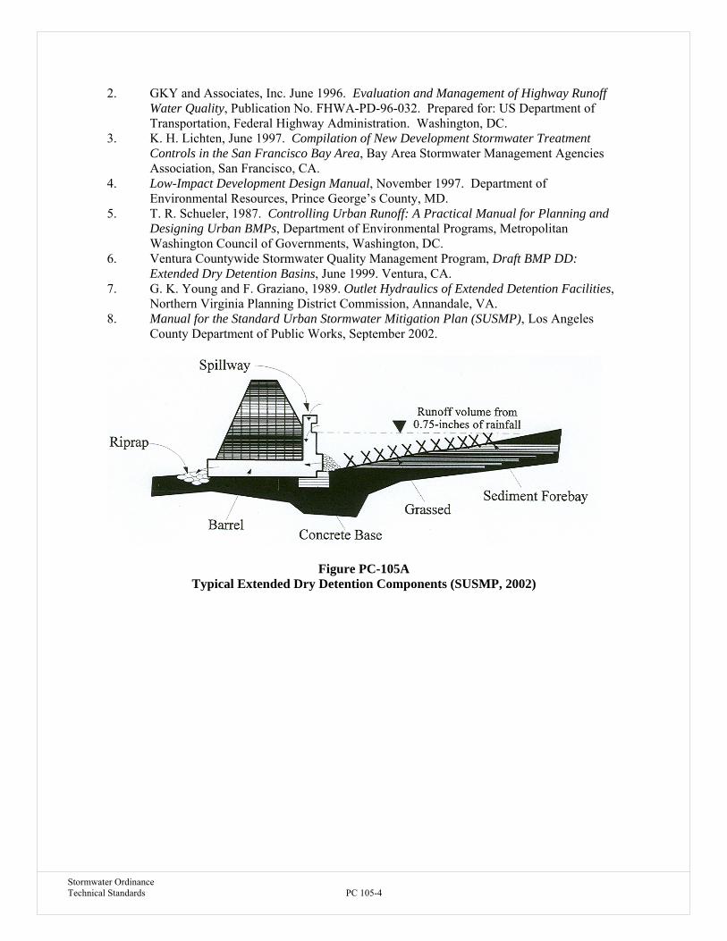
Stormwater Ordinance Technical Standards PC 105-4
2. GKY and Associates, Inc. June 1996. Evaluation and Management of Highway Runoff Water Quality, Publication No. FHWA-PD-96-032. Prepared for: US Department of Transportation, Federal Highway Administration. Washington, DC.
3. K. H. Lichten, June 1997. Compilation of New Development Stormwater Treatment Controls in the San Francisco Bay Area, Bay Area Stormwater Management Agencies Association, San Francisco, CA.
4. Low-Impact Development Design Manual, November 1997. Department of Environmental Resources, Prince George’s County, MD.
5. T. R. Schueler, 1987. Controlling Urban Runoff: A Practical Manual for Planning and Designing Urban BMPs, Department of Environmental Programs, Metropolitan Washington Council of Governments, Washington, DC.
6. Ventura Countywide Stormwater Quality Management Program, Draft BMP DD: Extended Dry Detention Basins, June 1999. Ventura, CA.
7. G. K. Young and F. Graziano, 1989. Outlet Hydraulics of Extended Detention Facilities, Northern Virginia Planning District Commission, Annandale, VA.
8. Manual for the Standard Urban Stormwater Mitigation Plan (SUSMP), Los Angeles County Department of Public Works, September 2002.
Figure PC-105A
Typical Extended Dry Detention Components (SUSMP, 2002)

Stormwater Ordinance Technical Standards PC 105-5
Figure PC-105B Typical Underground Detention Components (SUSMP, 2002)

Stormwater Ordinance Technical Standards PC 106-1
DESCRIPTION
An infiltration basin is a surface pond which captures first-flush stormwater and treats it by allowing it to percolate into the ground and through permeable soils. As the stormwater percolates into the ground, physical, chemical, and biological processes occur which remove both sediments and soluble pollutants. Pollutants are trapped in the upper layers of the soil, and the water is then released to groundwater. Infiltration basins are generally used for drainage areas between 5 and 50 acres (Boutiette and Duerring, 1994). For drainage areas less than 5 acres, an infiltration trench or other BMP may be more appropriate. For drainage areas greater than 50 acres, maintenance of an infiltration basin would be burdensome, and an extended/dry detention basin or wet pond may be more appropriate. Infiltration basins are generally dry except immediately following storms, but a low-flow channel may be necessary if a constant base flow is present.
Infiltration basins create visible surface ponds that dissipate because water is infiltrated through the pond bottom; infiltration trenches hide surface drainage in underground void regions and the water is infiltrated below the rocks. Infiltration basins effectively remove soluble pollutants because processes such as adsorption and biological processes remove these soluble pollutants from stormwater. This kind of treatment is not always available in other kinds of BMPs.
Several types of infiltration basins exist. They can be either in-line or off-line, and may treat different volumes of water, such as the water quality volume or the 2-year or 10-year storm. A full infiltration basin is built to hold the entire water quality volume, and the only outlet from the pond is an emergency spillway. More commonly used is the combined infiltration/detention basin, where the outflow is controlled by a vertical riser. Excess flow volume spills over the drop inlet at the top of the riser, and very large storms will exit through the emergency spillway. Other types of basins include the side-by-side basin, and the off-line infiltration basin. The side by side basin consists of a basin with an elevated channel to carry base flows running along one of its sides. Storm flows also flow through the elevated channel, but overflow the channel and enter the basin when they become deep enough. An off-line infiltration basin is used to treat the first flush runoff, while higher flows remain in the main channel.
ADVANTAGES
1. High removal capability for particulate pollutants and moderate removal for soluble pollutants.
2. Groundwater recharge helps to maintain dry-weather flows in streams. 3. Can minimize increases in runoff volume. 4. When properly designed and maintained, it can replicate pre-development hydrology
more closely than other BMP options. 5. Basins provide more habitat value than other infiltration systems.
BMP PC – 106 INFILTRATION BASINS
Stormwater Ordinance Technical Standards PC 106-2
LIMITATIONS
1. High failure rate due to clogging and high maintenance burden. 2. Low removal of dissolved pollutants in very coarse soils. 3. Not suitable on fill slopes or steep slopes. 4. Risk of groundwater contamination in very coarse soils, may require groundwater
monitoring. 5. Should not be used if significant upstream sediment load exists. 6. Slope of contributing watershed needs to be less than 20 percent. 7. Not recommended for discharge to a sole source aquifer. 8. Cannot be located within 100 feet of drinking water wells. 9. Metal and petroleum hydrocarbons could accumulate in soils to potentially toxic levels. 10. Relatively large land requirement. 11. Only feasible where soil is permeable and there is sufficient depth to bedrock and water
table. 12. Need to be located a minimum of 10 feet down gradient and 100 feet up gradient from
building foundations because of seepage problems. 13. Infiltration facilities could fall under additional regulations of IDEM or IDNR regarding
waste disposal to groundwater.
DESIGN CRITERIA
Designing an infiltration basin is a process in which several factors are examined. The soil type and the drainage area are important factors in infiltration basin design. If either one of these two is inappropriate, the infiltration basin will not function properly. The steps in the design of an infiltration basin are listed below.
1. Drainage Area. Drainage areas between 5 and 50 acres are good candidates for infiltration basins. Infiltration trenches might be more appropriate for smaller drainage areas, while retention ponds are more appropriate for larger drainage areas (Schueler, 1987).
2. Soils. The site must have the appropriate soil, or the basin will not function properly. It is important that the soil be able to accept water at a minimum infiltration rate. Soils with an infiltration rate of less than 0.3 inches per hour, are not suitable sites for infiltration basins. Soils with a high percentage of clay are also undesirable, and should not be used if the percentage of clay is greater than 30. Generally, areas with fine to moderately fine soils are prevalent should not be considered as sites, because these soils do not have a high infiltration rate. Soils with greater than 40 percent combined silt/clay also should not be used. A series of soil cores should be taken to a depth of at least 5 feet below the proposed basin floor elevation to determine which kinds of soils are prevalent at the potential site.
3. Volume. Calculate the volume of stormwater to be mitigated by the infiltration basin using the Methods of Chapter 9.
4. Slope. The basin floor should be as flat as possible to ensure an even infiltration surface and should not be or greater than 5 percent slope. Also, side slopes should have a maximum slope of 3 horizontal to 1 vertical (Schueler, 1987).
5. Vegetation. Vegetation should be established as soon as possible. Water-tolerant reed canary grass or tall fescue should be planted on the floor and side slopes of the basin (Schueler, 1987). Root penetration and thatch formation maintains and sometimes

Stormwater Ordinance Technical Standards PC 106-3
improves infiltration capacity of the basin floor. Also, the vegetation helps to trap the pollutants by growing through the accumulated sediment and preventing resuspension. The vegetation also helps reduce pollution levels by taking up soluble nutrients for growth and converting them into less available pollutant forms.
6. Inlet. Sediment forebays or riprap aprons should be installed to reduce flow velocities and trap sediments upon entrance to the basin. Flow should be evenly distributed over the basin floor by a riprap apron. The inlet pile or channel should enter the basin at floor level to prevent erosion (Schueler, 1987).
7. Drainage Time. The basin should completely drain within 24 hours to avoid the risk of it not being empty before the next storm. Overestimation of the future infiltration capacity can result in a standing water problem. Ponds with detention times of less than six hours are not effectively removing pollutants from the storm flows (Schueler, 1987). The most common problem is setting the elevation and size of the low-flow orifice. If the orifice is too large, runoff events pass through the basin too quickly. If the low-flow orifice diameter is too narrow, there is a risk of creating an undesirable quasi-permanent pool.
8. Buffer Zone. A 25 foot buffer should be placed between the edge of the basin floor, and the nearest adjacent lot (Schueler, 1987). The buffer should consist of water tolerant, native plant species that provide food and cover for wildlife. This buffer zone may also act as a screen if necessary.
9. Access. Access to the basin floor should be provided for light equipment (Schueler, 1987).
10. Water Table. The basin floor should be a minimum of 10 feet above the water table. 11. Maximum Depth. The maximum allowable depth is equal to the infiltration rate
multiplied by the maximum allowable dewatering time (24 hours). 12. Freeboard. A minimum of 2 feet of freeboard should be available between the spillway
crest and the top of the dam (Dormann, et al., 1988). 13. Emergency Spillway. The emergency spillway should be able to safely pass the 100-year
flood. 14. Surface Area of the Basin Floor. If the surface area of the basin floor is increased, the
infiltration rate and quantity of runoff which can be infiltrated will be increased. Larger surface areas can also help compensate for clogging on the surface.
REFERENCES
1. L. N. Boutiette and C. L. Duerring, 1994. Massachusetts Nonpoint Source Management Manual, The Megamanual: A Guidance Document for Municipal Officials, Massachusetts Department of Environmental Protection, Office of Watershed Management, Nonpoint Source Program, Boston, MA.
2. Camp, Dresser and McKee, Inc., Larry Walker Associates, 1993. California Best Management Practices - Municipal, California State Water Resources Council Board, Alameda, CA.
3. M. E. Dormann, J. Hartigan, and B. Maestri, 1988. Retention, Detention, and Overland
Flow for Pollutant Removal from Highway Stormwater Runoff: Interim Guidelines for Management Measures, FHWA/RD-87/056, Federal Highway Administration, Versar, Inc., Springfield, VA.
4. GKY and Associates, Inc. June 1996. Evaluation and Management of Highway Runoff Water Quality, Publication No. FHWA-PD-96-032. Prepared for: US Department of Transportation, Federal Highway Administration. Washington, DC.

Stormwater Ordinance Technical Standards PC 106-4
5. T. R. Schueler, 1987. Controlling Urban Runoff: A Practical Manual for Planning and Designing Urban BMPs, Department of Environmental Programs, Metropolitan Washington Council of Governments, Washington, DC.
6. Ventura Countywide Stormwater Quality Management Program, Draft BMP IN: Infiltration Facilities, June 1999. Ventura, CA.
7. Manual for the Standard Urban Stormwater Mitigation Plan (SUSMP), Los Angeles County Department of Public Works, September 2002.

Stormwater Ordinance Technical Standards PC 107-1
C.7 INFILTRATION TRENCHES
DESCRIPTION
An infiltration trench is basically an excavated trench that has been lined with filter fabric and backfilled with stone to form an underground basin. Runoff is diverted into the trench and either infiltrates into the soil, or enters a perforated pipe underdrain and is routed to an outflow facility. The depths of an infiltration trench generally range between 3 and 8 feet (Schueler, 1987) and may change when site-specific factors are considered. Smaller trenches are used for water quality, while larger trenches can be constructed if stormwater quantity control is required (Schueler, 1987). Trenches are not usually feasible in ultra-urban or retrofit situations where the soils have low permeability or low voids (Schueler, 1992). They should be installed only after the contributing area has stabilized to minimize runoff of sediments.
Infiltration trenches and infiltration basins follow similar design logic. The differences are that the former is for small drainage areas and stores runoff out of sight, within a gravel or aggregate matrix, whereas the latter is for larger drainage areas and water is stored in a visible surface pond.
Infiltration trenches effectively remove soluble and particulate pollutants. They can provide groundwater recharge by diverting 60 to 90 percent of annual urban runoff back into the soil (Boutiette and Duerring, 1994). They are generally used for drainage areas less than 10 acres, but some references cite 5 acres as a maximum size drainage area (Schueler, 1987, 1992). Potential locations include residential lots, commercial areas, parking lots, and adjacent to road shoulders. Trenches are only feasible on permeable soils (sand and gravel), and where the water table and bedrock are situated well below the bottom of the trench (Boutiette and Duerring, 1994; Schueler, 1987). Trenches are frequently used in combination with grassed sales. Trenches should not be used to trap course sediments, because the large sediment will clog the trench. Grass buffers can be installed to capture sediment before it enters the trench.
ADVANTAGES
1. Provides groundwater recharge. 2. Trenches fit into small areas. 3. Good pollutant removal capabilities. 4. Can minimize increases in runoff volume. 5. Can fit into medians, perimeters, and other unused areas of a development site. 6. Helps replicate pre-development hydrology and increases dry weather base flow.
LIMITATIONS
1. Slope of contributing watershed needs to be less than 20 percent. 2. Soil should have infiltration rate greater than 0.3 inches per hour and clay content
less than 30 percent. 3. Drainage area should be between 1 to 10 acres. 4. The bottom of infiltration trench should be at least 4 feet above the underlying
BMP PC – 107 INFILTRATION TRENCHES
Stormwater Ordinance Technical Standards PC 107-2
bedrock and the seasonal high water table. 5. High failure rates of conventional trenches and high maintenance burden. 6. Low removal of dissolved pollutants in very coarse soils. 7. Not suitable on fill slopes or steep slopes. 8. Risk of groundwater contamination in very coarse soils, may require
groundwater monitoring. 9. Infiltration facilities could fall under additional regulations of IDEM or IDNR
regarding waste disposal to groundwater. 10. Cannot be located within 100 feet of drinking water wells. 11. Need to be located a minimum of 10 feet down gradient and 100 feet up gradient
from building foundations because of seepage problems. 12. Should not be used if upstream sediment load cannot be controlled prior to entry
into the trench. 13. Metals and petroleum hydrocarbons could accumulate in soils to potentially toxic
levels.
DESIGN CRITERIA
Infiltration trenches can be categorized both by trench type, and as surface or below ground. Special inlets are required for underground trenches to prevent sediment and oil or grease from clogging the infiltration trench (Schueler, 1987). Surface trenches are commonly used where land is not limiting and underground trenches are better suited for development with minimal land availabilities.
1. Volume. Calculate the volume of stormwater to be mitigated by the water quality volume calculation of Chapter 9. 2. Dimensions. Generally, soils with low infiltration rates require a higher ratio of bottom surface area to storage volume (Northern Virginia Planning District Commission and Engineers and Town Engineers Institute, 1992). The following formulas can be used to determine the dimensions of the infiltration basin:
HTmax=E*tmax/P
HTmin=E*tmin/P A=V/[ E*tmax]
Where:
HTmax, HTmin = Maximum and minimum trench depths (ft)
E = Infiltration rate in length per unit time (ft/hr). tmax, tmin = Maximum and minimum target drain-time (hr) P= Pore volume ratio of stone aggregate (% porosity/100). V= Fluid storage volume requirement (ft
3)
A= Trench bottom surface area (ft2).
Stormwater Ordinance Technical Standards PC 107-3
The actual storage volume of the facility is the void ratio multiplied by the total volume of the trench. The available land and other constraints such as depth to bedrock or water table are used to determine the final dimensions of the trench.
3. Buffer Strip/Special Inlet. A grass filter strip a minimum of 20 feet should surround the
trench on all sides over which surface flow reaches an above-ground trench. A special inlet can be used to prevent floatable material, solids, grease, and oil from entering trenches which are located below ground.
4. Filter Fabric. The bottom and sides of the trench should be lined with filter fabric soon after the trench is excavated. The fabric should be flush with the sides, overlap on the order of 2 feet over the seams, and not have trapped air pockets. As an alternative, 6 inches of clean, washed sand may be placed on the bottom of the trench instead of filter fabric.
5. Grass Cover. If the trench is grass covered, at least 1 foot of soil should be over the trench for grass substrate.
6. Surface Area. The surface area of the trench can be engineered to the site with the understanding that a larger surface area of the bottom of the trench increases infiltration rates and helps to reduce clogging and that depth may be limited by seasonal groundwater.
7. Surface Area of the Trench Bottom. Pollutant removal in a trench can be improved by increasing the surface area of the trench bottom. This is done by adjusting the geometry to make the trench shallow and broad, rather than deep and narrow. Greater bottom surface area increases infiltration rates and provides more area and depth for soil filtering. In addition, broader trench bottoms reduce the risk of clogging at the soil/filter cloth interface by spreading infiltration over a wider area.
8. Distance from Wells and Foundations. The trench should be at least 100 feet of any drinking water supply well, and at least 10 feet down gradient and 100 feet up gradient from building foundations (Schueler, 1987).
9. Drain Time. The drain time should be between two and three days. The total volume of the trench should drain in 48 hours. The minimum drain time should be 24 hours.
10. Backfill Material. The backfill material in the trench should have a D50 sized between 1.5 and 3 inches and clay content should be limited to less than 30 percent. The porosity of the material should be between 0.3 and 0.4.
11. Observation Well. An observation well of 4 to 6 inches diameter PVC should be located in the center of the trench and the bottom should rest on a plate. The top should be capped. The water level should be measured after a storm event. If it has not completely drained in three days, some remedial work may need to be done.
12. Overflow Berm. A 2 to 3 inch emergency overflow berm on the downstream side of the trench serves a twofold purpose. First, it detains surface runoff and allows it to pond and infiltrate to the trench. The berm also promotes uniform sheet flow for runoff overflow.

Stormwater Ordinance Technical Standards PC 107-4
REFERENCES
1. L. N. Boutiette and C. L. Duerring, 1994. Massachusetts Nonpoint Source Management Manual, The Megamanual: A Guidance Document for Municipal Officials, Massachusetts Department of Environmental Protection, Office of Watershed Management, Nonpoint Source Program, Boston, MA.
2. Camp, Dresser and McKee, Inc., Larry Walker Associates, 1993. California Best Management Practices - Municipal, California State Water Resources Council Board, Alameda, CA.
3. DEQ Storm Water Management Guidelines, Department of Environmental Quality, State of Oregon.
http://waterquality.deq.state.or.us/wq/groundwa/swmgmtguide.htm 4. M. E. Dormann, J. Hartigan, and B. Maestri, 1988. Retention, Detention, and Overland
Flow for Pollutant Removal from Highway Stormwater Runoff: Interim Guidelines for Management Measures, FHWA/RD-87/056, Federal Highway Administration, Versar, Inc., Springfield, VA.
5. GKY and Associates, Inc. June 1996. Evaluation and Management of Highway Runoff Water Quality, Publication No. FHWA-PD-96-032. Prepared for: US Department of Transportation, Federal Highway Administration. Washington, DC.
6. Low-Impact Development Design Manual, November 1997. Department of Environmental Resources, Prince George’s County, MD.
7. Northern Virginia Planning District Commission and Engineers Town Engineers Institute, 1992. Northern Virginia BMP Handbook, A Guide to Planning and Designing Best Management Practices in Northern Virginia, Annandale, VA.
8. T. R. Schueler, 1987. Controlling Urban Runoff: A Practical Manual for Planning and Designing Urban BMPs, Department of Environmental Programs, Metropolitan Washington Council of Governments, Washington, DC.
9. T. R. Schueler, P. Kumble, and M. Heraty, 1992. A Current Assessment of Urban Best Management Practices: Techniques for Reducing Nonpoint Source Pollution in the Coastal Zone, Anacostia Research Team, Metropolitan Washington Council of Governments, Washington, DC.
10. Ventura Countywide Stormwater Quality Management Program, Draft BMP IN: Infiltration Facilities, June 1999. Ventura, CA.
11. Manual for the Standard Urban Stormwater Mitigation Plan (SUSMP), Los Angeles County Department of Public Works, September 2002.

Stormwater Ordinance Technical Standards PC 108-1
C.8 MEDIA FILTRATION
DESCRIPTION OF SAND FILTERS
Media filters are two-stage constructed treatment systems, including a pretreatment settling basin and a filter bed containing sand or other filter media. Various types of sand filter designs have been developed and implemented successfully in space-limited areas. The filters are not designed to treat the entire storm volume but rather the water quality volume, that tends to contain higher pollutant levels. Sand filters can be designed so that they receive flow directly from the surface (via inlets or even as sheet flow directly onto the filter bed) or via storm drain pipes. They can be exposed to the surface or completely contained in underground pipe systems or vaults.
While there are various designs, most intermittent sand filters contain four basic components, as shown schematically in Figure 10-5 and discussed below: 1. Diversion Structure. Either incorporated into the filter itself or as a stand alone device,
the diversion structure isolates the WQV and routes it to the filter. Larger volumes are bypassed directly to the storm drain system.
2. Sedimentation Chamber. Important to the long-term successful operation of any filtration system is the removal of large grained sediments prior to exposure to the filter media. The sedimentation chamber is typically integrated directly into the sand filter BMP but can also be a stand alone unit if space permits.
3. Filter Media. Typically consists of a 1-inch gravel layer over an 18 to 24 inch layer of washed sand. A layer of geotextile fabric can be placed between the gravel and sand layers.
4. Underdrain System. Below the filter media is a gravel bed, separated from the sand by a layer of geotextile fabric, in which is placed a series of perforated pipes. The treated runoff is routed out of the BMP to the storm sewer system or another BMP.
ADVANTAGES
1. May require less space than other treatment control BMPs and can be located underground.
2. Does not require continuous base flow. 3. Suitable for individual developments and small tributary areas up to 100 acres. 4. Does not require vegetation. 5. Useful in watersheds where concerns over groundwater quality or site conditions prevent
use of infiltration. 6. High pollutant removal capability. 7. Can be used in highly urbanized settings. 8. Can be designed for a variety of soils. 9. Ideal for aquifer regions.
LIMITATIONS
BMP PC – 108 MEDIA FILTRATION

Stormwater Ordinance Technical Standards PC 108-2
1. Given that the amount of available space can be a limitation that warrants the consideration of a sand filter BMP, designing one for a large drainage area where there is room for more conventional structures may not be practical.
2. Available hydraulic head to meet design criteria. 3. Requires frequent maintenance to prevent clogging. 4. Not effective at removing liquid and dissolved pollutants. 5. Severe clogging potential if exposed soil surfaces exist upstream. 6. Sand filters may need to be placed offline to protect it during extreme storm events.
DESIGN CRITERIA 1. Treatment Rate. Calculate the flow rate of stormwater to be mitigated by the media filtration according to the method in Chapter 9. 2. Surface area of the filter. The following equation is for a maximum filtration time of 24 hours:
A. Surface Systems or Vaults Filter area (ft2) = 3630SuAH/K(D+H)
Where: Su = unit storage (inches-acre)
A = area in acres draining to facility H = depth (ft) of the sand filter D = average water depth (ft) over the filter taken to be one-half the difference between the top of the filter and the maximum water surface elevation K = filter coefficient recommended as 3.5
This equation is appropriate for filter media sized at a diameter of 0.02 to 0.04 inches. The filter area must be increased if a smaller media is used.
B. Underground Sandfilter Systems
a. Compute the required size of the sand filter bed surface area, AF. The following equation is based on Darcy's law and is used to size the sand filter bed area: AF (ft2) = 24(WQV)(df)/ [k (hf + df) tf] Where: Af = sand filter bed surface area (ft2)
WQV = Water quality treatment volume (ft3) df = sand filter bed depth (ft) k = filter coefficient recommended as 3.5 (ft/day) hf = average height of water above the sand bed (ft)= hmax/2 hmax = elevation difference between the invert of the inlet pipe and the top of the sand filter bed (ft) tf = time required for the runoff to filter through the sand bed (hr). (Typically 24 hr).
Note: 24 in the equation is the 24hr/day constant.
b. Choose a pipe size (diameter). The selection of pipe size should be based on site parameters such as: elevation of the runoff coming into the sand filter system, elevation of downstream connection to which the sand filter system

Stormwater Ordinance Technical Standards PC 108-3
outlet must tie into, and the minimum cover requirements for live loads. A minimum of 5' clearance should be provided between the top of the inner pipe wall and the top of the filter media for maintenance purpose. Use:
D = d + 5
Where: D = pipe diameter (ft) d = depth of sand filter and underdrain pipe media depth (ft) = dg + df dg = underdrain pipe media depth = 0.67’ df = sand filter bed deph (ft): 1.5 to 2.0 feet
c. Compute the sand filter width(based on the pipe geometry):
Wf = 2 [R2 - (R - d)2 ]0.5
Where: Wf = filter width (ft) R = pipe radius (ft) = D/2
d. Compute the filter length:
Lf = Af/ Wf Where: Lf = filter length (ft)
3. Configuration A. Surface sand filter
Criteria for the settling basin. a. For the outlet use a perforated riser pipe. b. Size the outlet orifice for a 24 hour drawdown c. Energy dissipater at the inlet to the settling basin. d. Trash rack at outlets to the filter. e. Vegetate slopes to the extent possible. f. Access ramp (4:1 or less) for maintenance vehicles. g. One foot of freeboard. h. Length to width ratio of at least 3:1 and preferably 5:1. i. Sediment trap at inlet to reduce resuspension. Criteria for the filter. a. Use a flow spreader. b. Use clean sand 0.02 to 0.04 inch diameter. c. Some have placed geofabric on sand surface to facilitate maintenance. d. Underdrains with:
- Schedule 40 PVC. - 4 inch diameter. - 3/8 inch perforations placed around the pipe, with 6 inch space between each perforation cluster. - maximum 10 foot spacing between laterals.

Stormwater Ordinance Technical Standards PC 108-4
- minimum grade of 1/8 inch per foot.
B. Underground sand filter Criteria for the settling tank (if required). a. Use orifice and/or weir structure for the outlet. b. Size the outlet orifice or weir for a 24 hour drawdown time c. Provide access manhole for maintenance. Criteria for the filter. a. Use a flow spreader. b. Use clean sand 0.02 to 0.04 inch diameter. c. Some have placed geofabric on sand surface to facilitate maintenance. d. Underdrains with:
- Schedule 40 PVC. - 4 inch diameter - 3/8 inch perforations placed around the pipe, with 6 inch space between each perforation cluster.
e. Provide access manhole for maintenance.
REFERENCES 1. Camp, Dresser and McKee, Inc., Larry Walker Associates, 1993. California Best
Management Practices - Municipal, California State Water Resources Council Board. Alameda, CA.
2. GKY and Associates, Inc. June 1996. Evaluation and Management of Highway Runoff
Water Quality, Publication No. FHWA-PD-96-032. Prepared for: US Department of Transportation, Federal Highway Administration. Washington, DC.
3. B. R. Urbonas, January/February 1999. Design of a Sand Filter for Stormwater Quality Enhancement, Water Environment Research, Volume 71, Number 1. Denver, CO.
4. Ventura Countywide Stormwater Quality Management Program, Draft BMP MF: Media Filters, June 1999. Ventura, CA.
5. Northern Virginia BMP Handbook, Town of Alexandria Virginia, February 1992. Alexandria, VI.
6. US EPA, Developments in Sand Filter Technology to Improve Runoff Quality, www.epa.gov/owowwtr1/NPS/wpt/wpt02/wpt02fa2.html.
7. Manual for the Standard Urban Stormwater Mitigation Plan (SUSMP), Los Angeles County Department of Public Works, September 2002.

Stormwater Ordinance Technical Standards PC 108-5
Figure PC-108A Typical Media Filtration Schematic (SUSMP, 2002)

Stormwater Ordinance Technical Standards PC 109-1
DESCRIPTION Storm drain inserts can be a variety of devices that are used in storm drain conveyance systems to reduce pollutant loadings in stormwater runoff. Most storm drain inserts reduce oil and grease, debris, and suspended solids through gravity, centrifugal force, or other methods. BMPs such as these can be particularly useful in areas susceptible to spills of petroleum products, such as gas stations. Figure 10-6 illustrates one of many different types of storm drain inserts. Trapped sediments and floatable oils must be pumped out regularly to maintain the effectiveness of the units.
ADVANTAGES
1. Prefabricated for different standard storm drain designs. 2. Require minimal space to install.
LIMITATIONS
1. Some devices may be vulnerable to accumulated sediments being resuspended during heavy storms.
2. Can only handle limited amounts of sediment and debris. 3. Maintenance and inspection of storm drain inserts are required before and after each
rainfall event. 4. High maintenance costs. 5. Hydraulic losses.
DESIGN CRITERIA
1. Calculate the minimum flow rate to be mitigated by the storm drain insert using the methods of Chapter 9.
2. Select unit which meets 80% TSS removal for design flow rate. 3. Provide an overflow to bypass flows greater than the water quality treatment rate.
REFERENCES
1. Center for Watershed Protection, Environmental Quality Resources and Loiederman Associates. 1997. Maryland Stormwater Design Manual. Prepared for: Maryland Department of the Environment. Baltimore, MD.
2. DEQ Storm Water Management Guidelines, Department of Environmental Quality, State of Oregon.
http://waterquality.deq.state.or.us/wq/groundwa/swmgmtguide.htm 3. K. H. Lichten, June 1997. Compilation of New Development Stormwater Treatment
Controls in the San Francisco Bay Area, Bay Area Stormwater Management Agencies Association, San Francisco, CA.
4. Manual for the Standard Urban Stormwater Mitigation Plan (SUSMP), Los
Angeles County Department of Public Works, September 2002.
BMP PC – 109 STORM DRAIN INSERTS / HYDROCARBON FILTERS

Stormwater Ordinance Technical Standards PC 109-2
Figure PC-109A Typical Storm Insert Schematic (SUSMP, 2002)
Stormwater Ordinance PC-110-1 Technical Standards
DESCRIPTION Vegetated filter strips, also known as vegetated buffer strips, are vegetated sections of land similar to grassed swales, except they are essentially flat with low slopes, and are designed only to accept runoff overland sheet flow (Schueler, 1992). They may appear in any vegetated form from grassland to forest, and are designed to intercept upstream flow, lower flow velocity, and spread water out as sheet flow (Schueler, 1992). The dense vegetative cover facilitates conventional pollutant removal through detention, filtration by vegetation, and infiltration into soil (Yu and Kaighn, 1992). Wooded and grass filter strips have slightly higher removal rates. Dissolved nutrient removal for either type of vegetative cover is usually poor, however wooded strips show slightly higher removal due to increased retention and sequestration by the plant community (Florida Department of Transportation, 1994). Although an inexpensive control measure, they are most useful in contributing watershed areas where peak runoff velocities are low, as they are unable to treat the high flow velocities typically associated with high impervious cover (Barret, et al., 1993). Similar to grassed swales, filter strips can last for 10 to 20 years with proper conditions and regular maintenance. Life expectancy is significantly diminished if uniform sheet flow and dense vegetation are not maintained. ADVANTAGES 1. Lowers runoff velocity (Schueler, 1987). 2. Slightly reduces runoff volume (Schueler, 1987). 3. Slightly reduces watershed imperviousness (Schueler, 1987). 4. Slightly contributes to groundwater recharge (Schueler, 1987). 5. Aesthetic benefit of vegetated “open spaces” (Colorado Department of Transportation, 1992). 6. Preserves the character of riparian zones, prevents erosion along streambanks, and provides excellent urban wildlife habitat (Schueler, 1992). LIMITATIONS 1. Filter strips cannot treat high velocity flows, and do not provide enough storage or infiltration to effectively reduce peak discharges to predevelopment levels for design storms (Schueler, 1992). This lack of quantity control dictates use in rural or low density development. 2. Requires slope less than 5%. 3. Requires low to fair permeability of natural subsoil. 4. Large land requirement. 5. Often concentrates water, which significantly reduces effectiveness. 6. Pollutant removal is unreliable in urban settings. DESIGN CRITERIA 1. Successful performance of filter strips relies heavily on maintaining shallow unconcentrated flow
(Colorado Department of Transportation, 1992). To avoid flow channelization and maintain performance, a filter strip should:
(1) Be equipped with a level spreading device for even distribution of runoff, (2) Contain dense vegetation with a mix of erosion resistant, soil binding species,
BMP PC – 110 VEGETATION FILTER STRIPS

Stormwater Ordinance PC-110-2 Technical Standards
(3) Be graded to a uniform, even and relatively low slope, (4) Laterally traverse the contributing runoff area (Schueler, 1987), (5) The area to be used for the strip should be free of gullies or rills that can concentrate
overland flow (Schueler, 1987), (6) Filters strip should be placed 3 to 4 feet from edge of pavement to accommodate a
vegetation free zone (Washington State Department of Transportation, 1995). The top edge of the filter strip along the pavement should be designed to avoid the situation where runoff would travel along the top of the filter strip, rather than through it. Dilhalla, et al., (1986) suggest that berms be placed at 50 to 100 feet intervals perpendicular to the top edge of the strip to prevent runoff from bypassing it (as cited in Washington State Department of Transportation, 1995),
(7) Top edge of the filter strip should follow the same elevation contour. If a section of the edge of the strip dips below the contour, runoff will tend to form a channel toward the low spot,
(8) Filter strips should be landscaped after other portions of the project are completed (Washington State Department of Transportation, 1995). However, level spreaders and strips used as sediment control measures during the construction phase can be converted to permanent controls if they can be regraded and reseeded to the top edge of the strip.
2. Filter strips can be used on an up gradient from watercourses, wetlands, or other water bodies, along toes and tops of slopes, and at outlets of other stormwater management structures (Boutiette and Duerring, 1994). They should be incorporated into street drainage and master drainage planning (Urbonas, 1992). The most important criteria for selection and use of this BMP are soils, space, and slope, where:
(1) Soils and moisture are adequate to grow relatively dense vegetative stands. Underlying
soils should be of low permeability so that the majority of the applied water discharges as surface runoff. The range of desirable permeability is between 0.06 to 0.6 inches/hour (Horner, 1985). Common soil textural classes are clay, clay loam, and silty clay. The presence of clay and organic matter in soils improves the ability of filter strips to remove pollutants from the surface runoff (Schueler, 1992). Greater removal of soluble pollutants can be achieved where the water table is within 3 feet of the surface (i.e., within the root zone) (Schueler, 1992). Filter strips function most effectively where the climate permits year-round dense vegetation.
(2) Sufficient space is available. Because filter strip effectiveness depends on having an evenly distributed sheet flow, the size of the contributing area and the associated volume runoff have to be limited (Urbonas, 1992). To prevent concentrated flows from forming, it is advisable to have each filter strip serve a contributing area of five acres or less (Schueler, 1987). When used alone, filter strip application is in areas where impervious cover is low to moderate and where there are small fluctuations in peak flow.
(3) Longitudinal slope is five percent or less. When filter strips are used on steep or unstable slopes, the formation of rills and gullies can disrupt sheet flow (Urbonas, 1992). As a result filter strips will not function at all on slopes greater than 15 percent and may have reduced effectiveness on slopes between 6 to 15 percent.
3. The design should be based on the same methods detailed for swales. The referred geometry of a filter strip is rectangular, and this should be used when applying the design procedures of vegetated swales.
4. The following provisions apply specifically to filter strips (Horner, 1993): (1) Slopes should be no greater than 15 percent and should preferably be lower than 5
percent, and be uniform throughout the strip after final grading. (2) Hydraulic residence time normally no less than 9 minutes, and in no case
less than 5 minutes.
Stormwater Ordinance PC-110-3 Technical Standards
(3) Average velocity no greater than 0.9 feet/second. (4) Manning’s friction factor (n) of 0.02 should be used for grassed strips, n of 0.024 if strip
is infrequently mowed, or a selected higher value if the strip is wooded. (5) The width should be no greater than that where a uniform flow distribution
can be assured. (6) Average depth of flow (design depth) should be no more than 0.5 inches. (7) Hydraulic radius is taken to be equal to the design flow depth. (8) A minimum of 8 feet is recommended for filter strip width.
5. Filter strips function best with longitudinal slopes less than 10 percent, and ideally less than 5 percent. As filter strip length becomes shorter, slope becomes more influential. Therefore, when a minimum strip length of 20 feet is utilized, slopes should be graded as close to zero as drainage permits (Schueler, 1987). With steeper slopes, terracing through using landscape timber, concrete weirs, or other means may be required to maintain sheet flow.
6. Calculate the flow rate of stormwater to be mitigated by the vegetated filter strip using the Method outlined in Chapter 9.
7. Another design issue is runoff collection and distribution to the strip, and release to a transport system or receiving water (Horner, 1985). Flow spreader devices should be used to introduce the flow evenly to the filter strip (Urbonas, 1992). Concentrated flow needs to use a level spreader to evenly distribute flow onto a strip. There are many alternative spreader devices, with the main consideration being that the overland flow spreader be distributed equally across the strip. Level spreader options include porous pavement strips, stabilized turf strips, slotted curbing, rock-filled trench, concrete sills, or plastic-lined trench that acts as a small detention pond (Yu and Kaighn, 1992). The outflow and filter side lip of the spreader should have a zero slope to ensure even runoff distribution (Yu and Kaighn, 1992). Once in the filter strip, most runoff from significant events will not be infiltrated and will require a collection and conveyance system. Grass-lined swales are often used for this purpose and can provide another BMP level. A filter strip can also drain to a storm sewer or street gutter (Urbonas, 1992).
8. Filter strips should be constructed of dense, soil-binding deep-rooted water resistant plants. For grassed filter strips, dense turf is needed to promote sedimentation and entrapment, and to protect against erosion (Yu and Kaighn, 1992). Turf grass should be maintained to a blade height of 2 to 4 inches. Most engineered, sheet-flow systems are seeded with specific grasses. The grass species chosen should be appropriate for the climatic conditions and maintenance criteria for each project.
9. Trees and woody vegetation have been shown to increase infiltration and improve performance of filter strips. Trees and shrubs provide many stormwater management benefits by intercepting some rainfall before it reaches the ground, and improving infiltration and retention through the presence of a spongy, organic layer of materials that accumulates underneath the plants (Schueler, 1987). As discussed previously in this section, wooded strips have shown significant increases in pollutant removal over grass strips. Maintenance for wooded strips is virtually non-existent, another argument for using trees and shrubs. However, there are drawbacks to using woody plants. Since the density of the vegetation is not as great as a turf grass cover, wooded filter strips need additional length to accommodate more vegetation. In addition, shrub and tree trunks can cause uneven distribution of sheet flow, and increase the possibility for development of gullies and channels. Consequently, wooded strips require flatter slopes than a typical grass cover strip to ensure that the presence of heavier plant stems will not facilitate channelization.
REFERENCES 1. M. E. Barret, R. D. Zuber, E. R. Collins, J. F. Malina, R. J. Charbeneau, and G. H.

Stormwater Ordinance PC-110-4 Technical Standards
Ward, 1993. A Review and Evaluation of Literature Pertaining to the Quantity and Control of Pollution from Highway Runoff and Construction, Center for Research in Water Resources, Bureau of Engineering Research, University of Texas at Austin, Austin, TX.
2. L. N. Boutiette and C. L. Duerring, 1994. Massachusetts Nonpoint Source Management Manual, The Megamanual: A Guidance Document for Municipal Officials, Massachusetts Department of Environmental Protection, Office of Watershed Management, Nonpoint Source Program, Boston, MA.
3. Camp, Dresser and McKee, Inc., Larry Walker Associates, 1993. California Best Management Practices - Municipal, California State Water Resources Council Board, Alameda, CA.
4. Colorado Department of Transportation, 1992, Erosion Control and Stormwater Quality Guide, Colorado Department of Transportation.
5. DEQ Storm Water Management Guidelines, Department of Environmental Quality, S t a t e o f O r e g o n . http://waterquality.deq.state.or.us/wq/groundwa/swmgmtguide.htm
6. Florida Department of Transportation, 1994. Water Quality Impact Evaluation Manual Training, Course No. BT-05-0009, Florida Department of Transportation.
7. GKY and Associates, Inc. June 1996. Evaluation and Management of Highway Runoff Water Quality, Publication No. FHWA-PD-96-032. Prepared for: US Department of Transportation, Federal Highway Administration. Washington, DC.
8. R. R. Horner, 1993. Biofiltration for Storm Runoff Water Quality Control, prepared for the Washington State Department of Ecology, Center for Urban Water Resources Management, University of Washington, Seattle, WA.
9. R. R. Horner, 1985. Highway Runoff Water Quality Research Implementation Manual, Volumes 1 and 2, Federal Highway Administration, WA-RD 72.2, Department of Civil Engineering, FX-10, University of Washington, Seattle, WA.
10. Indiana County Conservation District. Controlling Sediment Pollution from Light Duty Grave/Dirt Roads, U.S. Environmental Protection Agency, Bureau of Land and Water Conservation and Indiana County Conservation District, PA.
11. Low-Impact Development Design Manual, November 1997. Department of Environmental Resources, Prince George’s County, MD.
12. T. R. Schueler, 1987. Controlling Urban Runoff: A Practical Manual for Planning and Designing Urban BMPs, Department of Environmental Programs, Metropolitan Washington Council of Governments, Washington, DC.
13. T. R. Schueler, P. Kumble, and M. Heraty, 1992. A Current Assessment of Urban Best Management Practices: Techniques for Reducing Nonpoint Source Pollution in the Coastal Zone, Anacostia Research Team, Metropolitan Washington Council of Governments, Washington, DC.
14. B. R. Urbonas, J. T. Doerfer, J. Sorenson, J. T. Wulliman, and T. Fairley, 1992. Urban Storm Drainage Criteria Manual, Volume 3 - Best Management Practices, Stormwater Quality, Urban Drainage and Flood Control District, Denver, CO.
15. Ventura Countywide Stormwater Quality Management Program, Draft BMP BF: Biofilters, June 1999. Ventura, CA.
16. Washington State Department of Transportation, 1995. Highway Runoff Manual, Washington State Department of Transportation.
17. S. L. Yu,S. L. Kaighn, 1992. VDOT Manual of Practice for Planning Stormwater Management, Federal Highway Administration, FHWA/VA-R13, Virginia Department of Transportation Research Council, Charlottesville, VA.

Stormwater Ordinance PC-110-5 Technical Standards
Figure PC-110A Typical Buffer Strip (SUSMP, 2002)
Figure PC-110B
Typical Buffer Strip Schematic (SUSMP, 2002)

Stormwater Ordinance PC-111-1 Technical Standards
DESCRIPTION Vegetated swales are shallow vegetated channels to convey stormwater where pollutants are removed by filtration through grass and infiltration through soil. They look similar to, but are wider than, a ditch that is sized only to transport flow. They require shallow slopes and soils that drain well. Grassed swale designs have achieved mixed performance in pollutant removal efficiency. Moderate removal rates have been reported for suspended solids and metals associated with particulates such as lead and zinc. Runoff waters are typically not detained long enough to effectively remove very fine suspended solids, and swales are generally unable to remove significant amounts of dissolved nutrients. Pollutant removal capability is related to channel dimensions, longitudinal slope, and type of vegetation. Optimum design of these components will increase contact time of runoff through the swale and improve pollutant removal rates. Vegetated swales are primarily stormwater conveyance systems. They can provide sufficient control under light to moderate runoff conditions, but their ability to control large storms is limited. Therefore, they are most applicable in low to moderate sloped areas as an alternative to ditches and curb and gutter drainage. Their performance diminishes sharply in highly urbanized settings. Vegetated swales are often used as a pretreatment measure for other downstream BMPs, particularly infiltration devices. Enhanced vegetative swales utilize check dams and wide depressions to increase runoff storage and promote greater settling of pollutants. ADVANTAGES 1. Relatively easy to design, install and maintain. 2. Vegetated areas that would normally be included in the site layout, if designed for appropriate
flow patterns, may be used as a vegetated swale. 3. Relatively inexpensive. 4. Vegetation is usually pleasing to residents. LIMITATIONS 1. Irrigation may be necessary to maintain vegetative cover. 2. Potential for mosquito breeding areas. 3. Possibility of erosion and channelization over time. 4. Requires dry soils with good drainage and high infiltration rates for better pollutant removal. 5. Not appropriate for pollutants toxic to vegetation. 6. Large area requirements may make this BMP infeasible for some sites. 7. Used to serve sites less than 10 acres in size, with slopes no greater than 5 percent. 8. The seasonal high water table should be at least 2 feet below the surface. 9. Buildings should be at least 10 feet from the top of bank DESIGN CRITERIA Several criteria should be kept in mind when beginning swale design. These provisions, presented below, have been developed through a series of evaluative research conducted on swale performance.
BMP PC – 111 VEGETATIVE SWALE

Stormwater Ordinance PC-111-2 Technical Standards
Criteria for optimum swale performance (Horner, 1993) Parameter Optimal Criteria Minimum Criteria* Hydraulic Residence Time 9 min 5 min Average Flow Velocity ≤0.9 ft/s N/A Swale Width 8 ft 2 ft Swale Length 200 ft 100 ft Swale Slope 2 - 6% 1% Side Slope Ratio (horizontal:vertical)
4 : 1 2 : 1
Note: * Criteria at or below minimum values can be used when compensatory adjustments are made to the standard design. Specific guidance on implementing these adjustments will be discussed in the design section. The procedures described below were set forth by Horner, and unless otherwise cited, are set forth in Biofiltration for Stormwater Runoff Quality Control, published in 1993. The following steps are recommended to be conducted in order to complete a swale design:
(1) Determine the flow rate to the system. (2) Determine the slope of the system. (3) Select a swale shape (skip if filter strip design). (4) Determine required channel width. (5) Calculate the cross-sectional area of flow for the channel. (6) Calculate the velocity of channel flow. (7) Calculate swale length. (8) Select swale location based on the design parameters. (9) Select a vegetation cover for the swale. (10) Check for swale stability.
Recommended procedures for each task are discussed in detail below. 1. Determine Flow Rate to the System. Calculate the flow rate of stormwater to be mitigated by the
vegetated swale using the methods outlined in Chapter 9. Runoff from larger events should be designed to bypass the swale, consideration must be given to the control of channel erosion and destruction of vegetation. A stability analysis for larger flows (up to the 100-yr 24-hour) must be performed. If the flow rate approaches or exceeds 1 ft3/s, one or more of the design criteria above may be violated, and the swale system may not function correctly (Washington State Department of Transportation, 1995). Alternative measures to lower the design flow should be investigated. Possibilities include dividing the flow among several swales, installing detention to control release rate upstream, and reducing developed surface area to reduce runoff coefficient value and gain space for biofiltration (Horner, 1993).
2. Determine the Slope of the System. The slope of the swale will be somewhat dependent on where the swale is placed, but should be between the stated criteria of one and six percent.
3. Select a Swale Shape. Normally, swales are designed and constructed in a trapezoidal shape, although alternative designs can be parabolic, rectangular, and triangular. Trapezoidal cross-sections are preferred because of relatively wider vegetative areas and ease of maintenance (Khan, 1993). They also avoid the sharp corners present in V-shaped and rectangular swales, and offer better stability than the vertical walls of rectangular swales.
4. Determine Required Channel Width. Estimates for channel width for the selected shape can be obtained by applying Manning’s Equation:
Stormwater Ordinance PC-111-3 Technical Standards
213
2486.1 SARn
Q =
Where: Q = Flow (ft3/s). A = Cross-sectional area of flow (ft2). Rh = Hydraulic radius of flow cross section (ft). S = Longitudinal slope of biofilter (ft/ft). n = Manning's roughness coefficient.
A Manning's n value of 0.02 is used for routine swales that will be mowed with some regularity. For swales that are infrequently mowed, use a Manning's n value of 0.024. A higher n value can be selected if it is known that vegetation will be very dense (Khan, 1993).
Because the channel is wide, the hydraulic radius approaches the flow depth. Substituting the geometric equations for a trapezoidal channel into Manning’s equation, the bottom width (wb) and the top width (wt) for the trapezoid swale can be computed using the following equations:
ZySy
Qnwb −= 5.067.1486.1 and Zyww bt 2+=
Where: Q = Flow rate in ft3/s. n = Manning’s roughness coefficient y = Depth of flow. Z = The side slope in the form of Z:1.
Typically, the depth of flow in the channel (H) is set at 3 to 4 inches. Flow depth can also be determined by subtracting 2 inches from the expected grass height, if the grass type and the height it will be maintained is known. Values lower than 3 to 4 inches can be used, but doing so will increase the computed width of the swale (Washington State Department of Transportation, 1995).
Swale width computed should be between 2 to 8 feet. Relatively wide swales (those wider than 8 feet are more susceptible to flow channelization and are less likely to have uniform sheet flow across the swale bottom for the entire swale length. The maximum widths for swales is on the order of 10 feet, however widths greater than 8 feet should be evaluated to consider the effectiveness of the flow spreading design used and the likelihood of maintaining evenness in the swale bottom. Since length may be used to compensate for width reduction (and vice versa) so that area is maintained, the swale width can be arbitrarily set to 8 feet to continue with the analysis.
5. Calculate Cross-Sectional Area. Compute the cross-sectional area (A) for the swale. 6. Calculate the Velocity of the Channel Flow. Channel flow velocity (U) can be computed using the
continuity equation V (ft/sec)=Q(cfs)/A(ft2)
This velocity should be less than 0.9 ft/s, a velocity that was found to cause grasses to be flattened, reducing filtration. A velocity lower than this maximum value is recommended to achieve the 9-minute hydraulic residence time criterion, particularly in shorter swales (at V = 0.9

Stormwater Ordinance PC-111-4 Technical Standards
ft/s, a 485-ft swale is needed for a 9-min residence time and a 269-ft swale for a 5-min residence time).
If the value of V suggests that a longer swale will be needed than space permits, investigate how the design flow Q can be reduced, or increase flow depth (y) and/or swale width (wt) up to the maximum allowable values and repeat the analysis.
7. Calculate Swale Length. Compute the swale length (L) using the following equation: L=60Vtr
Where: L=length required to achieve residence time tr = Hydraulic residence time (in minutes). V=velocity of channel flow (ft/sec) Use tr = 9 min for this calculation.
If a swale length greater than the space will permit results, investigate how the design flow Q can be reduced. Increase flow depth (H) and/or swale width (wb) up to the maximum allowable values and repeat the analysis. If all of these possibilities are checked and space is still insufficient, t can be reduced, but to no less than 5 minutes. If the computation results in L less than 100 ft, set L = 100 ft and investigate possibilities in width reduction. This is possible through recalculating V at the 100-ft length, recomputing cross-sectional area, and ultimately adjusting the swale width wb using the appropriate equation.
8. Select Swale Location. Swale geometry should be maximized by the designer, using the above equations, and given the area to be utilized. If the location has not yet been chosen, it is advantageous to compute the required swale dimensions and then select a location where the calculated width and length will fit. If locations available cannot accommodate a linear swale, a wide-radius curved path can be used to gain length.
Sharp bends should be avoided to reduce erosion potential. Regardless of when and how site selection is performed, consideration should be given to the following site criteria:
Soil Type. Soil characteristics in the swale bottom should be conducive to grass growth. Soils that contain large amounts of clay cause relatively low permeability and result in standing water, and may cause grass to die. Where the potential for leaching into groundwater exists, the swale bottom may need to be sealed with clay to protect from infiltration into the resource. Compacted soils will need to be tilled before seeding or planting. If topsoil is required to facilitate grass seeding and growth, use 6 inches of the following recommended topsoil mix: 50 to 80 percent sandy loam, 10 to 20 percent clay, and 10 to 20 percent composted organic matter (exclude animal waste). Slope. The natural slope of the potential location will determine the nature and amount of regrading, or if additional measures to reduce erosion and/or increase pollutant removal are required. Swales should be graded carefully to attain uniform longitudinal and lateral slopes and to eliminate high and low spots. If needed, grade control checks should be provided to maintain the computed longitudinal slope and limit maximum flow velocity (Urbonas, 1992).
Natural Vegetation. The presence and composition of existing vegetation can provide valuable information on soil and hydrology. If wetland vegetation is present, inundated conditions may exist at the site. The presence of larger plants, trees and shrubs, may provide additional stabilization along the swale slopes, but also may shade any grass cover established. Most grasses grow best in full sunlight, and prolonged shading should be avoided. It is preferable that

Stormwater Ordinance PC-111-6 Technical Standards
vegetation species be native to the region of application, where establishment and survival have been demonstrated.
9. Select Vegetative Cover. A dense planting of grass provides the filtering mechanism responsible for water quality treatment in swales. In addition, grass has the ability to grow through thin deposits of sediment and sand, stabilizing the deposited sediment and preventing it from being resuspended in runoff waters. Few other herbaceous plant species provide the same density and surface per unit area. Grass is by far the most effective choice of plant material in swales, however not all grass species provide optimum vegetative cover for use in swale systems. Dense turf grasses are best for vegetative cover.
In areas of poor drainage, wetlands species can be planted for increased vegetative cover. Use wetland species that are finely divided like grass and relatively resilient. Invasive species, such as cattails, should be avoided to eliminate proliferation in the swale and downstream. Woody or shrubby plantings can be used for landscaping on the edge of side slopes, but not in the swale treatment area. Trees and shrubs can provide some additional stabilization, but also mature and shade the grass. In addition, leaf or needle drop can contribute unwanted nutrients, create debris jams, or interfere with waterflow through the system. If landscape plantings are to be used, selection and planting processes should be carefully planned and carried out to avoid these potential problems.
10. Check Swale Stability. The stability check is performed for the combination of highest expected flow and least vegetation coverage and height. Stability is normally checked for flow rate (Q) for the 100-yr, 24-h storm unless runoff from larger such events will bypass the swale. Q can be determined using the same methods mentioned for the initial design storm computation. The maximum velocity (Vmax) in ft/s, that is permissible for the vegetation type, slope, and soil conditions should be obtained.
REFERENCES 1. Camp, Dresser and McKee, Inc., Larry Walker Associates, 1993. California Best
Management Practices - Municipal, California State Water Resources Council Board, Alameda, CA.
2. Colorado Department of Transportation, 1992, Erosion Control and Stormwater Quality Guide, Colorado Department of Transportation.
3. DEQ Storm Water Management Guidelines, Department of Environmental Quality,State of Oregon.
http://waterquality.deq.state.or.us/wq/groundwa/swmgmtguide.htm 4. GKY and Associates, Inc. June 1996. Evaluation and Management of Highway Runoff Water
Quality, Publication No. FHWA-PD-96-032. Prepared for: US Department of Transportation, Federal Highway Administration. Washington, DC.
5. R. R. Horner, 1993. Biofiltration for Storm Runoff Water Quality Control, prepared for the Washington State Department of Ecology, Center for Urban Water Resources Management, University of Washington, Seattle, WA.
6. Z. Khan, C. Thrush, P. Cohen, L. Kuzler, R. Franklin, D. Field, J. Koon, and R. Horner, 1993. Biofiltration Swale Performance Recommendations and Design Considerations, Washington Department of Ecology, University of Washington, Seattle, WA.
7. K. H. Lichten, June 1997. Compilation of New Development Stormwater Treatment Controls in the San Francisco Bay Area, Bay Area Stormwater Management Agencies Association, San Francisco, CA.

Stormwater Ordinance PC-111-6 Technical Standards
8. Low-Impact Development Design Manual, November 1997. Department of Environmental Resources, Prince George’s County, MD.
9. T. R. Schueler, P. Kumble, and M. Heraty, 1992. A Current Assessment of Urban Best Management Practices: Techniques for Reducing Nonpoint Source Pollution in the Coastal Zone, Anacostia Research Team, Metropolitan Washington Council of Governments, Washington, DC.
10. B. R. Urbonas, J. T. Doerfer, J. Sorenson, J. T. Wulliman, and T. Fairley, 1992. Urban Storm Drainage Criteria Manual, Volume 3 - Best Management Practices, Stormwater Quality, Urban Drainage and Flood Control District, Denver, CO.
11. Ventura Countywide Stormwater Quality Management Program, Draft BMP BF: Biofilters, June 1999. Ventura, CA.
12. Washington State Department of Transportation, 1995. Highway Runoff Manual, Washington State Department of Transportation.
13. Manual for the Standard Urban Stormwater Mitigation Plan (SUSMP), Los Angeles County Department of Public Works, September 2002.
Stormwater Ordinance PC-112-1 Technical Standards
DESCRIPTION The wet pond or retention pond is a facility which removes sediment, Biochemical oxygen Demand (BOD), organic nutrients, and trace metals from stormwater runoff. This is accomplished by slowing down stormwater using an in-line permanent pool or pond effecting settling of pollutants. The wet pond is similar to a dry pond, except that a permanent volume of water is incorporated into the design. The drainage area should be such that an adequate base flow is maintained in the pond. Biological processes occurring in the permanent pond pool aid in reducing the amount of soluble nutrients present in the water, such as nitrate and ortho-phosphorus (Schueler, 1987). The basic elements of a wet pond are shown below. A stabilized inlet prevents erosion at the entrance to the pond. It may be necessary to install energy dissipaters. The permanent pool is usually maintained at a depth between 3 and 8 ft. The shape of the pool can help improve the performance of the pond. Maximizing the distance between the inlet and outlet provides more time for mixing of the new runoff with the pond water and settling of pollutants. Overflow from the pond is released through outlet structures to discharge flows at various elevations and peak flow rates. The outfall channel should be protected to prevent erosion from occurring downstream of the outlet. Soil conditions are important for the proper functioning of the wet pond. The pond is a permanent pool, and thus must be constructed such that the water must not be allowed to infiltrate from the permanent portion of the pool. It is difficult to form a pool in soils with high infiltration rates soon after construction. Eventually, however, deposition of silt at the bottom of the pond will help slow infiltration. If extremely permeable soils exist at the site (hydrologic soil group A or B), a geotextile or clay liner may be necessary. ADVANTAGES 1. Wet ponds have recreational and aesthetic benefits due to the incorporation of
permanent pools in the design. 2. Wet ponds offer flood control benefits in addition to water quality benefits. 3. Wet ponds can be used to handle large drainage areas. 4. High pollutant removal efficiencies for sediment, total phosphorus, and total nitrogen are
achievable when the volume of the permanent pool is at least three times the water quality volume (the volume to be treated).
5. A wet pond removes pollutants from water by both physical and biological processes, thus they are more effective at removing pollutants than extended/dry detention basins.
6. Creation of aquatic and terrestrial habitat. LIMITATIONS 1. Wet ponds may be feasible for stormwater runoff in residential or commercial areas with a
combined drainage area greater than 20 acres but no less than 10 acres. 2. An adequate source of water must be available to ensure a permanent pool throughout the entire
year. 3. If the wet pond is not properly maintained or the pond becomes stagnant; floating
debris, scum, algal blooms, unpleasant odors, and insects may appear.
BMP PC – 112 WET PONDS / RETENTION BASINS

Stormwater Ordinance PC-112-3 Technical Standards
4. Sediment removal is necessary every 5 to 10 years. 5. Heavy storms may cause mixing and subsequent resuspension of solids. 6. Evaporation and lowering of the water level can cause concentrated levels of salt and algae to
increase. 7. Cannot be placed on steep unstable slopes. 8. Could be regulated as a wetlands or Waters of the US by IDEM. 9. Embankment may be regulated as a dam by IDNR. DESIGN CRITERIA 1. Hydrology. If the device will also be used for stormwater quantity control, it will be necessary to
reduce the peak flows after development to the levels described in Chapter 6. 2. Volume. Calculate the volume of stormwater to be mitigated by the wet pond using the water
quality volume calculations in Chapter 9. The volume of the permanent pool should be 3 times this water quality volume.
3. Pond Shape. The pond should be long and narrow and generally shaped such that it discourages “short-circuiting.” Short-circuiting occurs when storm flows by-pass the pond and do not mix well with the pool and simply by-pass the pond. Short-circuiting can be discouraged by lengthening the pond or by installing baffles which slow water down and lengthen the distance between the inlet and outlet. A length to width ratio of no less than 2:1, with 4:1 being preferred, will help minimize short circuiting. Also, the pond should gradually expand from the inlet and gradually contract toward the outlet. Several examples of ponds shaped to reduce short-circuiting are shown below.
4. Depth. The depth of the water quality pond is important in the design of the pond. If the pond is too shallow, sediment will be easily resuspended as a result of wind. Shallow ponds should not be used unless vegetation is adequate to stabilize the pond. If the pond is too deep, safety considerations emerge and stratification may occur, possibly causing anoxic conditions near the bottom of the pond. If the pond becomes anoxic, pollutants adsorbed to the bottom sediments may be released back to the water column. The average depth should be 3 to 6 ft, and depths of more than 8 ft should be avoided (Schueler, 1987). A littoral zone of 6 to 18 inches deep that accounts for 25 to 50 percent of the permanent pool surface for plant growth along the perimeter of the pool is recommended, the littoral shelf will also enhance safety.
5. Vegetation. Planting vegetation around the perimeter of the pond can have several advantages. Vegetation reduces erosion on both the side slopes and the shallow littoral areas. Vegetation located near the inlet to the pond can help trap sediments; algae growing on these plants can also filter soluble nutrients in the water column. Thicker, higher vegetation can also help hide any debris which may collect near the shoreline. Native turf-forming grasses or irrigated turf should be planted on sloped areas, and aquatic species should be planted on the littoral areas (Urbonas, et al., 1992). Vegetation can benefit wildlife and waterfowl by providing food and cover at the marsh fringe. A shallow, organic-rich marsh fringe provides an area which enables bacteria and other microorganisms to reduce organic matter and nutrients (Schueler, 1987).
6. Side Slopes. Gradual side slopes of a wet pond enhance safety and help prevent erosion and make it easier to establish dense vegetation. If vegetation cannot be established, the unvegetated banks will add to erosion and subsequently the sediment load. It is recommended that side slopes be no greater than 3:1. If slopes are greater than this, riprap should be used to stabilize the banks (Schueler, 1987).
7. Hydraulic Devices. An outlet device, typically a riser-pipe barrel system, should be designed to release runoff in excess of the water quality volume and to control storm peaks. The outlet device should still function properly when partial clogging occurs. Plans should provide details on all culverts, risers, and spillways. Calculations should depict inflow, storage, and outflow characteristics of the design. Some frequently used design details for extending detention times in wet ponds are shown and described below (Schueler, 1987):
Stormwater Ordinance PC-112-3 Technical Standards
a. Slotted Standpipe from Low-Flow Orifice, Inlet Control (dry pond, shallow wet pond, or shallow marsh). An “L”-shaped PVC pipe is attached to the low-flow orifice. An orifice plate is located within the PVC pipe which internally controls the release rate. Slots or perforations are all spaced vertically above the orifice plate, so that sediment deposited around the standpipe will not impede the supply of water to the orifice plate. b. Negatively Sloped Pipe from River (wet ponds or shallow marshes) This design was developed to allow for extended detention in wet ponds. The release rate is governed merely by the size of the pipe. The risk of clogging is largely eliminated by locating the opening of the pipe at least 1 ft below the water surface where it is away from floatable debris. Also, the negative slope of the pipe reduces the chance that debris will be pulled into the opening by suction. As a final defense against clogging, the orifice can be protected by wire mesh. c. Hooded Riser (wet ponds). In this design, the extended detention orifice is located on the face of the riser near the top of the permanent pool elevation. The orifice is protected by wire mesh and a hood, which prevents floatable debris from clogging the orifice.
8. Inlet and Outlet Protection. The inlet pipe should discharge at or below the water surface of the permanent pool. If it is above the pool, an outlet energy dissipater will protect the banks and side slopes of the pond to avoid erosion. The stream channel just downstream of the pond outlet should be protected from scouring by placing riprap along the channel. Also, the slope of the outlet channel should be close to 0.5 percent. Riprap between 18 and 30 inches should be used. If the outlet pipe is less than 24 inches, 9 to 12 inches riprap may be used. Stilling basins may also be installed to reduce flow velocities at the outfall (Schueler, 1987).
9. Forebay. A forebay may be installed as part of the wet pond to capture sand and gravel sediment. The forebay should be easily accessible for dredging out the sediment when necessary and access to the forebay for equipment should be provided. The forebay volume should typically be 5 to 10 percent of the water quality volume. If there are multiple inlets to the detention facility, each forebay should be sized based on the portion of water quality volume attributed to the particular inlet.
10. Emptying Time. A 12 to 48 hour emptying time may be used for the water quality volume above the permanent pool (Urbonas, et al., 1992).
11. Freeboard. The pond embankment should have at least 1 ft of freeboard above the emergency spillway crest elevation (Schueler, 1987).
REFERENCES 1. Camp, Dresser and McKee, Inc., Larry Walker Associates, 1993. California Best Management
Practices - Municipal, California State Water Resources Council Board, Alameda, CA. 2. GKY and Associates, Inc. June 1996. Evaluation and Management of Highway Runoff Water
Quality, Publication No. FHWA-PD-96-032. Prepared for: US Department of Transportation, Federal Highway Administration. Washington, DC.
3. K. H. Lichten, June 1997. Compilation of New Development Stormwater Treatment Controls in the San Francisco Bay Area, Bay Area Stormwater Management Agencies Association, San Francisco, CA.
4. T. R. Schueler, 1987. Controlling Urban Runoff: A Practical Manual for Planning and Designing Urban BMPs, Department of Environmental Programs, Metropolitan Washington Council of Governments, Washington, DC.
5. B. R. Urbonas, J. T. Doerfer, J. Sorenson, J. T. Wulliman, and T. Fairley, 1992. Urban Storm Drainage Criteria Manual, Volume 3 - Best Management Practices, Stormwater Quality, Urban Drainage and Flood Control District, Denver, CO.
6. Manual for the Standard Urban Stormwater Mitigation Plan (SUSMP), Los Angeles County Department of Public Works, September 2002.

Stormwater Ordinance PC-112-4 Technical Standards
Figure PC-112A Typical Wet Pond Components (SUSMP, 2002)
Figure PC-112B Strategies to Increase residence time in detention facilities (SUSMP, 2002)

Stormwater Ordinance PC-112-5 Technical Standards
Figure PC-112C Typical Outlet Structure Modifications to increase residence time of water quality volume (SUSMP,
2002)

Stormwater Ordinance Technical Standards
DESCRIPTION: Pervious pavement consists of a permeable surface course underlain by a uniformly-graded stone bed which provides temporary storage for peak rate control and promotes infiltration. The surface course may consist of porous asphalt, porous concrete, or various porous structural pavers laid on uncompacted soil. ADVANTAGES: 1. When designed properly, pavement can handle almost entire storm peak flows. 2. Minimizes safety risks of falling/slipping in rain or on ice. 3. Volume reduction in run off by providing storm water storage that can also prevent
potential property damage from flooding. 4. Can improve water quality and recharge storm water into subsurface. 5. Can greatly reduce impervious areas calculations during design. LIMITATIONS: Special Maintenance Considerations: 1. Prevent clogging of pavement surface with sediment 2. Vacuum pavement 2 or 3 times per year 3. Maintain planted areas adjacent to pavement 4. Immediately clean any soil deposited on pavement 5. Do not allow construction staging, soil/mulch storage, etc. on unprotected pavement
surface 6. Clean inlets draining to the subsurface bed twice a year COST ISSUES: 1. Pervious asphalt, with additives is generally 10% to 20% higher in cost than standard
asphalt on a unit area basis. 2. Pervious concrete as a material is generally more expensive than asphalt and requires
more labor and experience for installation due to specific material constraints. 3. Permeable interlocking concrete pavement blocks vary in cost depending on type and
manufacturer. DESIGN CRITERIA 1. Site Location. Need well draining soils outside of low, wet areas. 2. Soil Testing. Need multiple soil testing locations and a deep hole visual inspection. Need
to know the depth of water table, limiting soil layers, location of bedrock and whether or not there has been past disturbance on the potential site.
3. Installation. A certified contractor is required for installation of pervious pavement. REFERENCES 1. Paul A. DeBarry, P.E., P.H., 2007. Pennsylvania Stormwater Best Management Practices
Manual – Chapter 6 – structural bmp’s – soil infiltration-based bmp’s.
BMP LID – 101 PERVIOUS PAVEMENT WITH INFILTRATION BED

Stormwater Ordinance Technical Standards

Stormwater Ordinance Technical Standards
DESCRIPTION: Vegetated roofs, also known as green roofs or eco-roofs, are structural components that help to mitigate the effects of urbanization on water quality by filtering, absorbing, or detaining rainfall. They reduce runoff pollutant loadings through a variety of physical, biological and chemical treatment processes that filter pollutants and reduce the volume of roof runoff. There are two basic types of green roofs: extensive and intensive. Extensive roofs form a thin vegetated sheath of self-sufficient mosses, sedums, and small shrubs. Their low profile allows them to be added to existing buildings, including those with sloping roofs. By contrast, intensive roofs are integral to the roof structure, permitting the use of trees and walkways. A greater depth of media and a greater roof structural capacity may be required to accommodate larger vegetation and surface features. WATER QUANTITY CONTROL: Green roofs store rainwater in the soil layer, reducing the volume and peak discharge rate of roof runoff. The storage capacity can be estimated using equation 1. The equation is based on the fundamental principle of soil porosity and should be considered a general guideline. More complex calculations which route runoff through the green roof can be used for detailed analysis. Green roofs are generally sized to store the water quality volume (WQV), or the first 0.5” of rainfall. Adding additional soil depth will increase the storage capacity. Equation1: storage volume = (green roof area) * (soil depth) * (soil porosity) Part of the stored runoff will be retained on the roof and lost to evapotranspiration, and part of it will percolate down to the drainage layer and ultimately become surface runoff. The water retention capacity of the soil is dependent upon both the properties of the soil substrate and the vegetative cover, as well as climactic conditions. DESIGN CONSTRUCTION AND MATERIALS: Green roofs consist of several layers. From the bottom up, they are the waterproof membrane, root barrier, insulation layer, drainage layer, growing medium, and vegetation. A drainage layer is needed for flat roofs but may not be necessary for sloped roofs. A leak detection layer is optional. The primary design variable is whether to construct an intensive or extensive roof, as described above. The decision may be influenced by the property owner’s desired maintenance level and by the roof’s structural capacity. Soil depth is another design variable and will determine the water storage capacity. Because most roofs are designed to handle snow loads, roof structures should easily be able to support the weight of a saturated extensive green roof. Intensive green roofs may require additional structural capacity. Green roof plants are hardy, self-sustaining, drought-resistant plants mainly from the genuses Sedum and Delosperma and are available from a variety of vendors. Costs for extensive green roofs are approximately $15 to $20 per square foot for all use types (e.g. high density residential, commercial, and industrial). These costs include all green roof
BMP LID – 102 VEGETATED/GREEN ROOF
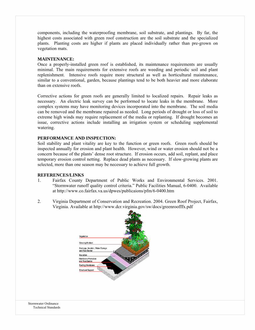
Stormwater Ordinance Technical Standards
components, including the waterproofing membrane, soil substrate, and plantings. By far, the highest costs associated with green roof construction are the soil substrate and the specialized plants. Planting costs are higher if plants are placed individually rather than pre-grown on vegetation mats. MAINTENANCE: Once a properly-installed green roof is established, its maintenance requirements are usually minimal. The main requirements for extensive roofs are weeding and periodic soil and plant replenishment. Intensive roofs require more structural as well as horticultural maintenance, similar to a conventional, garden, because plantings tend to be both heavier and more elaborate than on extensive roofs. Corrective actions for green roofs are generally limited to localized repairs. Repair leaks as necessary. An electric leak survey can be performed to locate leaks in the membrane. More complex systems may have monitoring devices incorporated into the membrane. The soil media can be removed and the membrane repaired as needed. Long periods of drought or loss of soil to extreme high winds may require replacement of the media or replanting. If drought becomes an issue, corrective actions include installing an irrigation system or scheduling supplemental watering. PERFORMANCE AND INSPECTION: Soil stability and plant vitality are key to the function or green roofs. Green roofs should be inspected annually for erosion and plant health. However, wind or water erosion should not be a concern because of the plants’ dense root structure. If erosion occurs, add soil, replant, and place temporary erosion control netting. Replace dead plants as necessary. If slow-growing plants are selected, more than one season may be necessary to achieve full growth. REFERENCES/LINKS 1. Fairfax County Department of Public Works and Environmental Services. 2001.
“Stormwater runoff quality control criteria.” Public Facilities Manual, 6-0400. Available at http://www.co.fairfax.va.us/dpwes/publicaions/pfm/6-0400.htm
2. Virginia Department of Conservation and Recreation. 2004. Green Roof Project, Fairfax,
Virginia. Available at http://www.dcr.virginia.gov/sw/docs/greenroofffx.pdf

Stormwater Ordinance Technical Standards
LEVEL SPREADERS
DESCRIPTION & APPLICATIONS: A level spreader is an outlet at zero grade across the slope of a vegetated or mechanical structure used to disperse or “spread” concentrated flow thinly over a receiving area. Its purpose is to spread collected water over a wide enough area so that erosion of the receiving area does not result. It can reduce erosion and the movement of sediment. An additional benefit of a level spreader is to remove other pollutants from runoff by filtration, infiltration, absorption, decomposition, and volatilization. This practice applies:
• Where concentrated water is dispersed within wooded buffers or on fields adjacent to streams, ponds, and lakes; and
• In areas requiring a filter strip such as a buffer to treat runoff. This practice shall not be used:
• Where drainage areas above it are greater than 10 acres. For greater drainage areas, use vegetated waterways, lined waterways, or grade control structures.
• Where the water discharge will cross an adjoining property line unless it can be intercepted by a stable drainageway capable of handling the added volume.
CONSIDERATIONS:
• A level spreader must be installed correctly with 0% grade on the spreader lip to ensure a uniform distribution of flow; otherwise water will channelize below the structure and become a source of erosion.
• Consider the time of year available for proper establishment of vegetation prior to construction of the level spreader. If a grass cover needs to be installed in the receiving area, construction will be limited to the growing season.
• Stable receiving swales should exist below the receiving area as concentrated flow can be expected to start occurring within about 300 feet. Evaluate slopes and soil material, vegetative species and their condition on the receiving area shall before constructing a level spreader.
• Provisions for mowing and otherwise managing the vegetation on the receiving area shall be planned to maintain the effectiveness of the filter area.
SPECIFICATIONS: Capacity:
The capacity of each level spreader shall be based on the allowable velocity of the soil. The minimum length shall be 12 feet. Typically, a level spreader should be sized to transfer 0.25 cfs per linear foot of spreader during the 10-year storm. Receiving Area: Each level spreader shall have a vegetated receiving area with the capacity to pass the flow without erosion. The receiving area shall be stable prior to the construction of the level spreader. The receiving area shall have a somewhat flat topography to prevent undue flow concentration before entering a stable watercourse. Approach Velocity:
BMP LID – 103 LEVEL SPREADER

Stormwater Ordinance Technical Standards
The flow area upstream of the level spreader shall be sufficient to ensure a low approach velocity to the level “lip.” The minimum flow area of level spreader shall be equal to four times the flow of the delivery channel. The lip shall be installed at a 0% grade. Construction: The receiving area below the level spreader shall be protected from harm during construction. Minor disturbed areas shall be stabilized with vegetative measures. A temporary storm water diversion may be necessary until the level spreader has fully stabilized. Level spreaders must blend smoothly into the downstream receiving area without any sharp drops or irregularities, to avoid channelization, turbulence and hydraulic “jumps.” Level spreaders shall be constructed on undisturbed soil where possible. If fill is used, it shall be constructed of material compacted of 95% of standard proctor test levels prior to seeding for that area not considered the seedbed.
MAINTENANCE: After construction and until fully re-vegetated, the level spreaders need to be carefully inspected for any signs of channelization and immediately repaired. The structure will fail if water exits from it in a channelized flow. Vegetated level spreaders may require periodic mowing. Spreaders constructed of wood, asphalt, stone or concrete also require periodic inspection to check for damage and to be repaired as needed. Over time, the level spreader may fill with sediment and will need to be cleaned out to maintain its capacity. REFERENCES/LINKS: 1. Maine, Erosion and Sediment Control BMP. 2003. Section E-4-2 “Level Spreaders” 2. Stormwater Management Manual. 2008. Eugene Oregon, Section 2-70 “Level Spreaders”
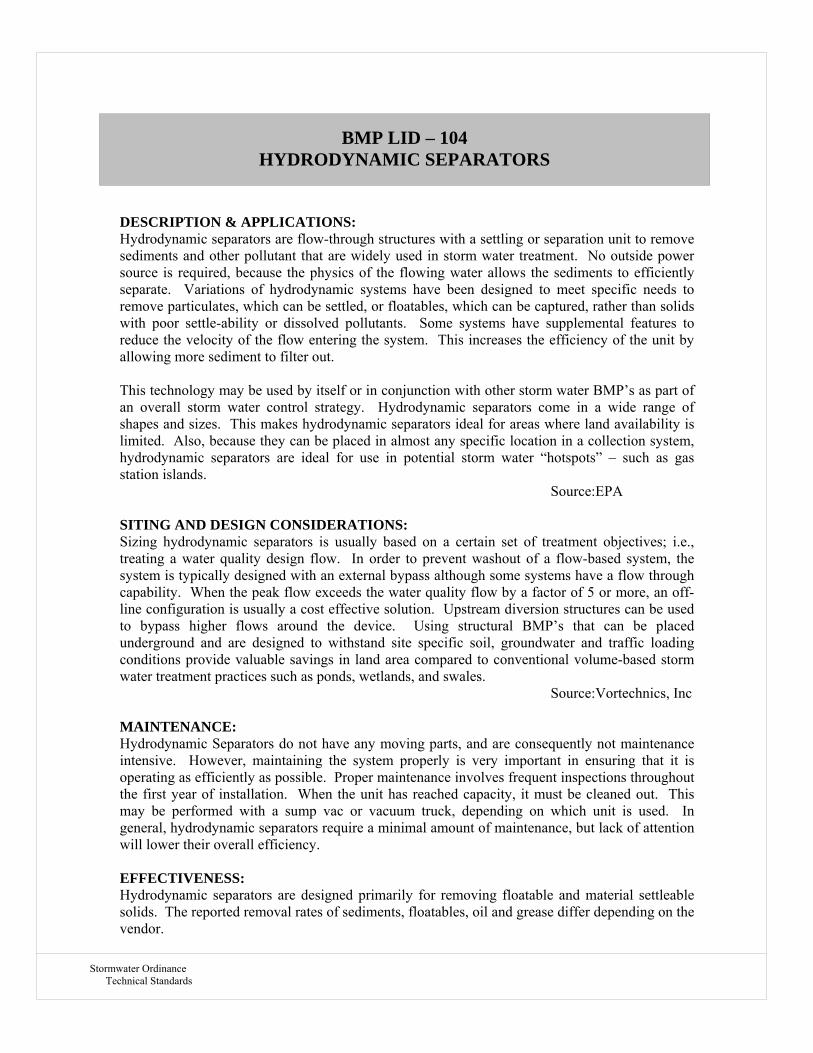
Stormwater Ordinance Technical Standards
DESCRIPTION & APPLICATIONS: Hydrodynamic separators are flow-through structures with a settling or separation unit to remove sediments and other pollutant that are widely used in storm water treatment. No outside power source is required, because the physics of the flowing water allows the sediments to efficiently separate. Variations of hydrodynamic systems have been designed to meet specific needs to remove particulates, which can be settled, or floatables, which can be captured, rather than solids with poor settle-ability or dissolved pollutants. Some systems have supplemental features to reduce the velocity of the flow entering the system. This increases the efficiency of the unit by allowing more sediment to filter out. This technology may be used by itself or in conjunction with other storm water BMP’s as part of an overall storm water control strategy. Hydrodynamic separators come in a wide range of shapes and sizes. This makes hydrodynamic separators ideal for areas where land availability is limited. Also, because they can be placed in almost any specific location in a collection system, hydrodynamic separators are ideal for use in potential storm water “hotspots” – such as gas station islands. Source:EPA SITING AND DESIGN CONSIDERATIONS: Sizing hydrodynamic separators is usually based on a certain set of treatment objectives; i.e., treating a water quality design flow. In order to prevent washout of a flow-based system, the system is typically designed with an external bypass although some systems have a flow through capability. When the peak flow exceeds the water quality flow by a factor of 5 or more, an off-line configuration is usually a cost effective solution. Upstream diversion structures can be used to bypass higher flows around the device. Using structural BMP’s that can be placed underground and are designed to withstand site specific soil, groundwater and traffic loading conditions provide valuable savings in land area compared to conventional volume-based storm water treatment practices such as ponds, wetlands, and swales. Source:Vortechnics, Inc MAINTENANCE: Hydrodynamic Separators do not have any moving parts, and are consequently not maintenance intensive. However, maintaining the system properly is very important in ensuring that it is operating as efficiently as possible. Proper maintenance involves frequent inspections throughout the first year of installation. When the unit has reached capacity, it must be cleaned out. This may be performed with a sump vac or vacuum truck, depending on which unit is used. In general, hydrodynamic separators require a minimal amount of maintenance, but lack of attention will lower their overall efficiency. EFFECTIVENESS: Hydrodynamic separators are designed primarily for removing floatable and material settleable solids. The reported removal rates of sediments, floatables, oil and grease differ depending on the vendor.
BMP LID – 104 HYDRODYNAMIC SEPARATORS
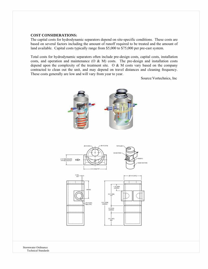
Stormwater Ordinance Technical Standards
COST CONSIDERATIONS: The capital costs for hydrodynamic separators depend on site-specific conditions. These costs are based on several factors including the amount of runoff required to be treated and the amount of land available. Capital costs typically range from $5,000 to $75,000 per pre-cast system. Total costs for hydrodynamic separators often include pre-design costs, capital costs, installation costs, and operation and maintenance (O & M) costs. The pre-design and installation costs depend upon the complexity of the treatment site. O & M costs vary based on the company contracted to clean out the unit, and may depend on travel distances and cleaning frequency. These costs generally are low and will vary from year to year. Source:Vortechnics, Inc

Stormwater Ordinance Technical Standards
DESCRIPTION & PURPOSE: Constructed channels are part of extensive portions of productive agricultural land in the United States. These channels provide important drainage and flood control functions. However, these agricultural channels are often constructed as traditional trapezoidal ditches using threshold design techniques. While this approach is suitable in some areas, channels of this design can require frequent and expensive maintenance in parts of the country. In addition, natural ecological functions are normally not a consideration in the design of these channels. This alternative to a conventional trapezoidal channel is known as a two stage ditch. This two stage channel system incorporates benches that function as flood plains and attempts to restore or create some natural alluvial channel processes. However, these two stage channels are not an exact copy of natural stream, as the width of the benches is often small due to the conflicting geometry of the constructed channel. This two stage approach provides improved physical, as well as ecological performances. The channel-forming discharge channel provides the necessary sediment conveyance, while the flood plain channel provides for the design flood conveyance. By nesting the channel-forming discharge channel within the larger channel, the entire waterway is more stable. ADVANTAGES: Benefits of a two stage ditch over a conventional trapezoidal ditch are potentially both improved drainage function and ecological function. Drainage benefits may include increased ditch stability and reduced maintenance. Evidence and theory both suggest that ditches prone to filling with accumulated sediment may require less frequent dipping out if constructed in a two stage form. Second, channel stability may be improved by a reduction in the erosive potential of larger flows as they are shallower and spread out across the bench. Stability of the ditch bank should be improved where the toe of the ditch bank meets the bench, rather than the ditch bottom. Here the water depth is effectively reduced, and the shear stress on the toe of the bank is less. Also, not being in contact with low flow, this bank material will be dryer and can be stabilized with vegetation using threshold design techniques. Since a two stage channel in an alluvial system will be more likely to retain its shape, it is easier to predict its flood protection performance. The biggest advantage of these two stage channels is the ability to transport sediment more effectively. However, the two stage ditch also has the potential to create and maintain better habitat than a conventional trapezoidal ditch. The narrow, deep bankfull channel provides better water depth during periods of low flow. Grass on the benches can provide some instream cover and shade. The substrate in the bankfull channel is improved as the two stage form increases sediment conveyance and sorting, with fines deposited on the benches and coarser material forming on the bed. DESIGN: Design and construction of two stage channels is different than that of traditional trapezoidal channels. The design of a two stage agricultural ditch in an alluvial channel system involves correctly sizing the bankfull channel and minimum bench widths for the flood plain bench. The
BMP LID – 105 TWO STAGE DITCH

Stormwater Ordinance Technical Standards
dimensions of the bankfull discharge or fluvial channel dictate the two stage channel design. If properly sized, the bankfull channel will be maintained by fluvial processes and will reduce or possibly even eliminate large-scale channel maintenance. The flood plain bench serves as a flood plain for the smaller bankfull channel, but it acts more as a threshold channel. The upper stage must convey the channel forming discharge and must have an adequate size to prevent design flood flows from overtopping the ditch banks and flooding surrounding land. CONSIDERATIONS: Creating a low bench typically requires the top width of the ditch to be greater than what would be requires for a traditional trapezoidal channel. It is important to note that the wider ditch top width results in the surrendering of surrounding agricultural production land. To offset landowner costs, the potential for including the bench width in buffer conservation programs should be considered. Buffers have typically been measures from the top of the ditch. Alternatively measuring from the top of the small channel to include the bench and the main side slope of the ditch is preferable from a water quality perspective and profitability perspective. Designers need to check local requirements for drainage easement standards. The elevation of the benches and size of the bankfull channel can be determined from regional curves that relate channel dimensions to drainage area. The design approach considers the magnitude and design frequency of discharges for both stages of the channel. It is anticipated that total bench widths that are two to four times the bankfull channel width will result in a stable geometry and a channel with low sinuosity. The overall conveyance capacities of these two stage systems can be sized based on the probability of out-of-ditch flooding into adjacent areas. Construction of a two stage channel system requires a significant capital investment to create a wider design top width. However, it is anticipated that two stage systems will have improved conveyance capacity, be more self-sustaining, and create and maintain improved aquatic habitat. REFERENCES: United States Department of Agriculture & the Natural Resources Conservation Service, 2007 –“National Engineering Handbook – Chapter 10 – Two-Stage Channel Design”
Stormwater Ordinance Technical Standards
DESCRIPTION: Riparian, or streamside, buffers are designed to maintain or restore streamside land in its natural vegetated state, in order to take advantage of the benefits that a forest’s biological processes can provide to aquatic ecosystems. They are forested strips of land along a stream that “buffer”, or protect, the stream from the impact of human activities. Preventing harmful pollutants from entering the stream benefits the entire aquatic ecosystem, as well as people who use the stream for swimming, fishing, boating, and as a source of drinking water. Trees and shrubs along the stream are more beneficial than grass-lined streambank. BENEFITS: Riparian buffers have numerous water quality and stream protection benefits. They include: 1) protecting streams from contaminants carried in runoff, such as fertilizers, pesticides, sediment, grease, oil and chemicals; 2) helping to alleviate localized flooding by decreasing the amount of runoff entering local streams immediately after a storm; 3) helping to reduce streambank erosion by roots holding the soil into place, minimizing the erosive force of the stream; 4) helping to recharge groundwater supply by providing infiltration; 5) protecting the habitat by providing a shade canopy that protects the stream from the sun’s heat, which keeps the water temperature cool during the summer; 6) supply food, shelter, and breeding habitat for fish and other organisms through leaves and woody debris that fall into the stream; 7) providing habitat for terrestrial species; and 8) improving streamside aesthetics and promoting recreational uses. DESIGN: A review of available sources indicates that there are a wide variety of buffer designs in use. Buffers can be found from a few feet to several hundred feet. Some designs incorporate width modifications for site conditions such as slope, upslope drainage area and soil infiltration capacity. Some designs are developed not only for water quality but for wildlife habitat and corridors. To be effective, a buffer must have sufficient width to allow filtration and infiltration processes to occur. It is also critical that water flow into and across the buffer as sheet flow rather than concentrated flow. Concentrated flows will likely cause erosion and will also reduce the buffers filtering and storage capacity. Two common designs are the forested buffer and the three zone buffer. In the forested buffer, the entire width is planted or preserved as undisturbed forest. The second common design is the three zone design in which the interior zone closet to the stream (zone 1), is undisturbed forest. It protects the stream bank and streamside environment. The middle zone, (zone 2) is upland from zone 1 and is maintained as trees and shrubs. This area is suitable for light uses such as footpaths. With the exception of periodic removal of trees, this zone should remain undisturbed. Periodic harvesting of trees fosters nutrient removal as the new trees remove nutrients while growing. The outside zone, (zone 3) is maintained as ground cover or grass. This zone should be shaped to convert flow to sheet flow into zone 2. The vegetation also helps filter sediment. The widths of the three zones vary by source of design. Buffer design should be considered carefully and include consideration of the objectives of the buffer, available resources for protecting an existing buffer or installing a new buffer inside existing easements and any maintenance requirements.
BMP LID – 106 RIPARIAN BUFFER RESTORATION

Stormwater Ordinance Technical Standards
BUFFER MANAGEMENT: Once a buffer is established, maintenance is key to its success. The following tips will help ensure that a buffer system functions effectively over the long term: 1) designate a buffer manager who will perform buffer inspections and maintenance; 2) conduct annual buffer inspections assessing streambank erosion and human and livestock damage; 3) plant additional trees, shrubs and ground cover, if necessary, to compensate for excessive losses; 4) inspect the buffer for gully formation after severs storms; 5) remove piles of debris completely blocking streamflow; 6) control weeds for two or three growing seasons; and 7) remove invasive plant species. REFERENCES: A cooperative project between the Dauphin County Conservation District and the Manada Conservancy, 2007 –“Swatara Creek Forested Riparian Buffer Project”

Stormwater Ordinance Technical Standards
DESCRIPTION: Reconstructed wetlands are constructed basins that have a permanent pool of water throughout the year (or at least throughout the wet season) and differ from wet ponds primarily in being shallower and having greater vegetation coverage. The schematic diagram is of an on-line pond that includes detention for larger events, but this is not required in all areas of the state. A distinction should be made between using a constructed wetland for storm water management and diverting storm water into a natural wetland. The latter practice is not recommended and in all circumstances, natural wetlands should be protected from the adverse effects of development, including impacts from increased storm water runoff. This is especially important because natural wetlands provide storm water and flood control benefits on a regional scale. Wetlands are among the most effective stormwater practices in terms of pollutant removal and they also offer aesthetic value. As stormwater runoff flows through the wetland, pollutant removal is achieved through settling and biological uptake within the wetland. Flow through the root systems forces the vegetation to remove nutrients and dissolved pollutants from the stormwater. ADVANTAGES: If properly designed, constructed and maintained, wetland basins can provide substantial wildlife and wetlands habitat. Due to the presence of the permanent wet pool, properly designed and maintained wet basins can provide significant water quality improvement across a relatively broad spectrum of constituents including dissolved nutrients. Widespread application with sufficient capture volume can provide significant control of channel erosion and enlargement caused by changes to flow frequency relationships resulting from the increase of impervious cover in a watershed. LIMITATIONS: There may be some aesthetic concerns about a facility that looks swampy. Some concern about safety when constructed where there is public access. Mosquito and midge breeding is likely to occur in wetlands. Reconstructed wetlands cannot be placed on steep unstable slopes. There is a need for base flow or supplemental water if water level is to be maintained. Depending on volume and depth, pond designs may require approval from the State Division of Safety of Dams. Developers will also need to check with Indiana Department of Environmental Management and the Army Corp of Engineers for permit requirements for impacting existing wetlands. CONSTRUCTION / INSPECTION CONSIDERATIONS: In areas with porous soils an impermeable liner may be required to maintain an adequate permanent pool level. Outlet structures and piping should be installed with collars to prevent water from seeping through the fill and causing structural failure. Inspect facility after first large storm to determine whether the desired residence time has been achieved. PERFORMANCE: The processes that impact the performance of reconstructed wetlands are essentially the same as those operating in wet ponds and similar pollutant reduction would be expected. One concern about the long-term performance of wetlands is associated with the vegetation density. If vegetation covers the majority of the facility, open water is confined to a few well defined channels. This can limit mixing of the storm water runoff with the permanent pool and reduce
BMP LID – 107 WETLAND RESTORATION/CREATION

Stormwater Ordinance Technical Standards
the effectiveness as compared to a wet pond where a majority of the area is open water. SITING CRITERIA: Wet ponds are a widely applicable storm water management practice and can be used over a broad range of storm frequencies and sizes, drainage areas and land use types. Although they have limited applicability in highly urbanized settings and in arid climates, they have few other restrictions. Reconstructed wetlands may be constructed on- or off-line and can be sited at feasible locations along established drainage ways with consistent base flow. An off-line design is preferred. Constructed wetlands are often utilized in smaller sub-watersheds and are particularly appropriate in areas with residential land uses or other areas where high nutrient loads are considered to be potential problems (e.g., golf courses). Wetlands generally consume a fairly large area (typically 4-6 percent of the contributing drainage area), and these facilities are generally larger than wet ponds because the average depth is less. Wet basin application is appropriate in the following settings: (1) where there is a need to achieve a reasonably high level of dissolved contaminant removal and/or sediment capture; (2) in small to medium-sized regional tributary areas with available open space and drainage areas greater than about 10 ha (25 ac.); (3) where base flow rates or other channel flow sources are relatively consistent year-round; (4) in settings where wildlife habitat benefits can be appreciated. DESIGN GUIDELINES: Reconstructed wetlands generally feature relatively uniformly vegetated areas with depths of one foot or less and open water areas (25-50% of the total area) no more than about 1.2 m (4 feet) deep, although design configuration options are relatively flexible. Wetland vegetation is comprised generally of a diverse, local aquatic plant species. Reconstructed wetlands can be designed on-line or off-line and generally serve relatively smaller drainage areas than wet ponds, although because of the shallow depths, the footprint of the facility will be larger than a wet pond serving the same tributary area. The extended detention shallow wetland combines the treatment concepts of the dry extended detention pond and the constructed wetland. In this design, the water quality volume is detained above the permanent pool and released over 24 hours. In addition to increasing the residence time, which improves pollutant removal, this design also attenuates peak runoff rates. Consequently, this design alternative is recommended. Pretreatment incorporates design features that help to settle out coarse sediment particles. By removing these particles from runoff before they reach the large permanent pool, the maintenance burden of the pond is reduced. In ponds, pretreatment is achieved with a sediment forebay. A sediment forebay is a small pool (typically about 10 percent of the volume of the permanent pool). Coarse particles remain trapped in the forebay, and maintenance is performed on this smaller pool, eliminating the need to dredge the entire pond. Effective wetland design displays "complex microtopography." In other words, wetlands should have zones of both very shallow (<6 inches) and moderately shallow (<18 inches) wetlands incorporated, using underwater earth berms to create the zones. This design will provide a longer flow path through the wetland to encourage settling, and it provides two depth zones to encourage plant diversity. There are a variety of sizing criteria for determining the volume of the permanent pool, mostly related to the water quality volume (i.e., the volume of water treated for pollutant removal) or the average storm size in a particular area. In addition, several theoretical approaches to determination of permanent pool volume have been developed. However, there is little empirical evidence to support these designs. Consequently, a simplified method (i.e., permanent pool volume equal to twice the water quality volume) is recommended. Design features are also incorporated to ease maintenance of both the forebay and the main pool of ponds. Ponds should be designed with a maintenance access to the forebay to ease this relatively routine (every 5–7 year) maintenance

Stormwater Ordinance Technical Standards
activity. In addition, ponds should generally have a drain to draw down the pond for vegetation harvesting or the more infrequent dredging of the main cell of the pond. SUMMARY OF DESIGN RECOMMENDATIONS: (1) Facility Sizing – The basin should be sized to hold the permanent pool as well as the required water quality volume. The volume of the permanent pool should equal twice the water quality volume. (2) Pond Configuration - The wet basin should be configured as a two stage facility with a sediment forebay and a main pool. The basins should be wedge-shaped, narrowest at the inlet and widest at the outlet. The minimum length to width ratio should be 1.5 where feasible. The depth in the center of the basin should be about 4 feet deep to prevent vegetation from encroaching on the pond open water surface. (3) Pond Side Slopes - Side slopes of the basin should be 3:1 (H:V) or flatter for grass stabilized slopes. Slopes steeper than 3:1 should be stabilized with an appropriate slope stabilization practice. (4) Sediment Forebay - A sediment forebay should be used to isolate gross sediments as they enter the facility and to simplify sediment removal. The sediment forebay should consist of a separate cell formed by an earthen berm, gabion, or loose riprap wall. The forebay should be sized to contain 15 to 25% of the permanent pool volume and should be at least 3 feet deep. Exit velocities from the forebay should not be erosive. Direct maintenance access should be provided to the forebay. The bottom of the forebay may be hardened (concrete) to make sediment removal easier. A fixed vertical sediment depth marker should be installed in the forebay to measure sediment accumulation. (5) Splitter Box - When the pond is designed as an off-line facility, a splitter structure is used to isolate the water quality volume. The splitter box, or other flow diverting approach, should be designed to convey the 25-year event while providing at least 1.0 foot of freeboard along pond side slopes. (6) Vegetation - A plan should be prepared that indicates how aquatic and terrestrial areas will be vegetatively stabilized. Wetland vegetation elements should be placed along the aquatic bench or in the shallow portions of the permanent pool. The optimal elevation for planting of wetland vegetation is within 6 inches vertically of the normal pool elevation. MAINTENANCE: The amount of maintenance required for reconstructed wetland is highly dependent on local regulatory agencies, particular health and vector control agencies. These agencies are often extremely concerned about the potential for mosquito breeding that may occur in the permanent pool. Routine harvesting of vegetation may increase nutrient removal and prevent the export of these constituents from dead and dying plants falling in the water. A previous study (Faulkner and Richardson, 1991) documented dramatic reductions in nutrient removal after the first several years of operation and related it to the vegetation achieving a maximum density. Vegetation harvesting in the summer is recommended. Typical maintenance activities and frequencies include: 1) Schedule semi-annual inspections for burrows, sediment accumulation, structural integrity of the outlet, and litter accumulation. 2) Remove accumulated trash and debris in the basin at the middle and end of the wet season. The frequency of this activity may be altered to meet specific site conditions and aesthetic considerations. 3) Where permitted by the Department of Natural Resources or other agency regulations, stock wet ponds/constructed wetlands regularly with mosquito fish (Gambusia spp.) to enhance natural mosquito and midge control.

Stormwater Ordinance Technical Standards
4) Introduce mosquito fish and maintain vegetation to assist their movements to control mosquitoes, as well as to provide access for vector inspectors. An annual vegetation harvest in summer appears to be optimum, in that it is after the bird breeding season, mosquito fish can provide the needed control until vegetation reaches late summer density, and there is time for re-growth for runoff treatment purposes before the wet season. In certain cases, more frequent plant harvesting may be required by local vector control agencies. 5) Maintain emergent and perimeter shoreline vegetation as well as site and road access to facilitate vector surveillance and control activities. 6) Remove accumulated sediment in the forebay and regrade about every 5-7 years or when the accumulated sediment volume exceeds 10 percent of the basin volume. Sediment removal may not be required in the main pool area for as long as 20 years. COST: Construction Cost Wetlands are relatively inexpensive storm water practices. Construction cost data for wetlands are rare, but one simplifying assumption is that they are typically about 25 percent more expensive than storm water ponds of an equivalent volume. Wetlands consume about 3 to 5 percent of the land that drains to them, which is relatively high compared with other storm water management practices. In areas where land value is high, this may make wetlands an infeasible option. Maintenance Cost For ponds, the annual cost of routine maintenance has typically been estimated at about 3 to 5 percent of the construction cost; however, the published literature is almost totally devoid of actual maintenance costs. Since ponds are long-lived facilities (typically longer than 20 years), major maintenance activities are unlikely to occur during a relatively short study. REFERENCES AND ADDITIONAL INFORMATION:
1. Amalfi, F.A., R. Kadlec, R.L. Knight, G. O'Meara, W.K. Reisen, W.E. Walton, and R. Wass. 1999. A mosquito control strategy for the Tres Rios Demonstration Constructed Wetlands. CH2M Hill, Tempe, AZ, 140 pp.
2. Borden, R. C., J.L. Dorn, J.B. Stillman, and S.K. Liehr; 1996. Evaluation of Ponds and Wetlands for Protection of Public Water Supplies. Draft Report. Water Resources Research Institute of the University of North Carolina, Department of Civil Engineering, North Carolina State University, Raleigh, NC.
3. City of Austin, TX. 1991. Design Guidelines for Water Quality Control Basins. Public Works Department, Austin, TX.
4. Cullum, M. 1985. Stormwater Runoff Analysis at a Single Family Residential Site. Publication 85-1. University of Central Florida, Orlando, FL. pp. 247–256.
5. Dorothy, J.M., and K. Staker. 1990. A Preliminary Survey for Mosquito Breeding in Stormwater Retention Ponds in Three Maryland Counties. Mosquito Control, Maryland Department of Agriculture, College Park, MD. 5 pp.
6. Faulkner, S. and Richardson, C., 1991, Physical And Chemical Characteristics of Freshwater Wetland Soils, in Constructed Wetlands for Wastewater Treatment, ed. D. Hammer, Lewis Publishers, 831 pp.
7. Gain, W.S. 1996. The Effects of Flow Path Modification on Water Quality Constituent Retentionin an Urban Stormwater Detention Pond and Wetland System. Water Resources Investigations Report 95-4297. U.S. Geological Survey, Tallahassee, FL.
8. Martin, E. 1988. Effectiveness Of An Urban Runoff Detention Pond/Wetland System. Journalof Environmental Engineering 114(4):810–827.
9. Maryland Department of the Environment (MDE). 2000. Maryland Stormwater Design Manual. http://www.mde.state.md.us/environment/wma/stormwatermanual.

Stormwater Ordinance Technical Standards
10. McLean, J. 2000. Mosquitoes In Constructed Wetlands: A Management Bugaboo? In T.R. Schueler and H.K. Holland [eds.], The Practice of Watershed Protection. pp. 29-33. Center for Watershed Protection, Ellicott City, MD
11. Metzger, M. E., D. F. Messer, C. L. Beitia, C. M. Myers, and V. L. Kramer. 2002. The Dark Side of Stormwater Runoff Management: Disease Vectors Associated with Structural BMPs. Stormwater 3(2): 24-39.
12. Oberts, G.L. 1994. Performance Of Stormwater Ponds And Wetlands In Winter. Watershed Protection Techniques 1(2):64–68.
13. Oberts, G.L., and L. Wotzka. 1988. The Water Quality Performance Of A Detention Basin Wetland Treatment System In An Urban Area. In Nonpoint Source Pollution: Economy, Policy, Management and Appropriate Technology. American Water Resources Association, Middleburg, VA.
14. Santana, F.J., J.R. Wood, R.E. Parsons, and S.K. Chamberlain. 1994. Control Of Mosquito Breeding In Permitted Stormwater Systems. Sarasota County Mosquito Control and Southwest Florida Water Management District, Brooksville, FL., 46 pp.
15. Saunders, G. and M. Gilroy, 1997. Treatment of Nonpoint Source Pollution with Wetland/Aquatic Ecosystem Best Management Practices. Texas Water Development Board, Lower Colorado River Authority, Austin, TX.
16. Schueler, T. 1997a. Comparative Pollutant Removal Capability Of Urban BMPs: A Reanalysis. Watershed Protection Techniques 2(4):515–520.
17. Urbonas, B., J. Carlson, and B. Vang. 1994. Joint Pond-Wetland System in Colorado. Denver Urban Drainage and Flood Control District, Denver, CO.
18. Water Environment Federation and ASCE, 1998, Urban Runoff Quality Management, WEF Manual of Practice No. 23 and ASCE Manual and Report on Engineering Practice No. 87.
19. Wu, J. 1989. Evaluation of Detention Basin Performance in the Piedmont Region of North Carolina. Report No. 89-248. North Carolina Water Resources Research Institute, Raleigh, NC.

Stormwater Ordinance Technical Standards
DESCRIPTION: Cluster development (also known as open space development) concentrates development on smaller lots on a portion of a larger site. Clustering allows the site planner to avoid resource sensitive and constrained areas at a site, such as steep slopes and water-sensitive areas including riparian buffers, wetlands, and floodplains without sacrificing the level of development. Clustering reduces the amount of required infrastructure and various development- related costs. Clustering lends itself to residential development, with greatest potential in municipalities where large-lot residential development is typical. Clustering can reduce total impervious area and total disturbed areas at development sites, thereby reducing storm water peak rates of runoff, reducing total volume of runoff, and reducing nonpoint source pollutant loads. Cluster development is driven by reducing minimum lot size, though not necessarily changing the total number of lots or amount of development occurring. As lot sizes decrease, the portion of the site which remains as undisturbed open space increases. If clustering is done carefully, this remaining open space can and should include those areas which are most sensitive environmentally and/or which offer special value functions not otherwise protected from development (e.g., high-quality woodlands areas). ADVANTAGES:
• Reduces required infrastructure • Increases open space • Protects environmentally sensitive natural resources
APPLICATIONS: Residential Clustering The most common clustering option is residential clustering on new development. The lot and house placement should avoid major natural features such as floodplain and wetlands, but still substantially encroaches into woodlands and riparian buffer features. Such a development layout (“yield plan”) provides an estimate of a site’s capacity to accommodate lots and houses at the base density hypothetically allowed under a municipal zoning ordinance. Nonresidential Clustering Conventional nonresidential development (e.g., retail commercial development) can also be configured in the form of low-rise (one story), relatively low-density strip or “big box” centers. DESIGN CONSIDERATIONS: The design process for implementing clustering at a proposed development site can occur in a variety of ways. Randall Arendt’s Growing Greener: Putting Conservation into Local Codes (1997) provides clustering guidance in several straight-forward steps. The process typically begins with the applicant applying existing conventional code to the site with any necessary net outs to develop a “yield plan.” The purpose is to determine how many units can be developed conventionally: • Step 1: Identify land to be protected: Primary conservation areas, secondary conservation areas, and delineate potential development area. • Step 2: Locate house sites on potential development area
BMP LID – 108 CLUSTER DESIGN

Stormwater Ordinance Technical Standards
• Step 3: Connect with streets and trails • Step 4: Draw in lot lines STORMWATER FUNCTIONS: Volume and Peak Rate Cluster development is a technique that results in increased open space, which reduces storm water peak rate and volume. These open spaces are often associated with other BMPs from this manual, including preserving sensitive areas and protecting riparian corridors. These BMPs are not to be included in the disturbed storm water management area when calculating runoff volume. Any portion of the open space that is mitigated or revegetated/reforested should be included in the disturbed storm water management area, but may be granted credit in accordance with the applicable BMP for native revegetation, riparian buffer restoration, or minimize total disturbed area. Water Quality Improvement Clustering minimizes impervious areas and their associated pollutant loads, resulting in improved water quality. In addition, clustering preserves open space and other natural features, such as riparian corridors, which allow for increased infiltration of storm water and removal of pollutant loads. COSTS: Clustering is beneficial from a cost perspective. Costs to build clustered single-family residential homes is less due to less land clearing and grading, less road and sidewalk construction (including curbing), less lighting and street landscaping, potentially less sewer and water line construction, potentially less storm water collection system construction, and other economies of scale. Post-construction, clustering also reduces costs. A variety of studies from Rutgers University’s landmark Costs of Sprawl studies and later updates show that delivery of a variety of municipal services such as street maintenance, sewer and water services, and trash collection are more economical on a per person or per house basis when development is clustered. Furthermore, services such as police protection are made more efficient when residential development is clustered. Additionally, clustering has been shown to positively affect land values. Analyses of market prices of conventional development over time in contrast with comparable clustered residential developments (where size, type, and quality of the house itself is held constant) indicate that clustered development increases in value at a more rapid rate than conventionally designed developments. This is partly due to the proximity to permanently protected open space. REFERENCES:
1. Arendt, Randall. “Cluster Development, A Profitable Way to Some Open Space,” Land Development, Fall 1991.
2. Arendt, Randall. Rural by Design. Washington D.C.: Planners Press, 1994. 3. Chesapeake Bay Program and Redman/Johnston Associates. Beyond Sprawl: Land
Management Techniques to Protect the Chesapeake Bay, A Handbook for Local Governments, 1997.
4. Delaware Department of Natural Resources and Environmental Control and the Brandywine Conservancy. Conservation Design for Stormwater Management: A Design Approach to Reduce Stormwater Impacts from Land Development. Dover, DE, 1997.
5. Delaware Riverkeeper. 2001. Stormwater Runoff: Lost Resource or Community Asset? Washington Crossing, PA, 2001.
6. Greenbelt Alliance. “Factsheet: Urban Growth Boundaries,” 1996. 7. Growing Greener: Putting Conservation into Local Codes. Natural Lands Trust, Inc.,
1997
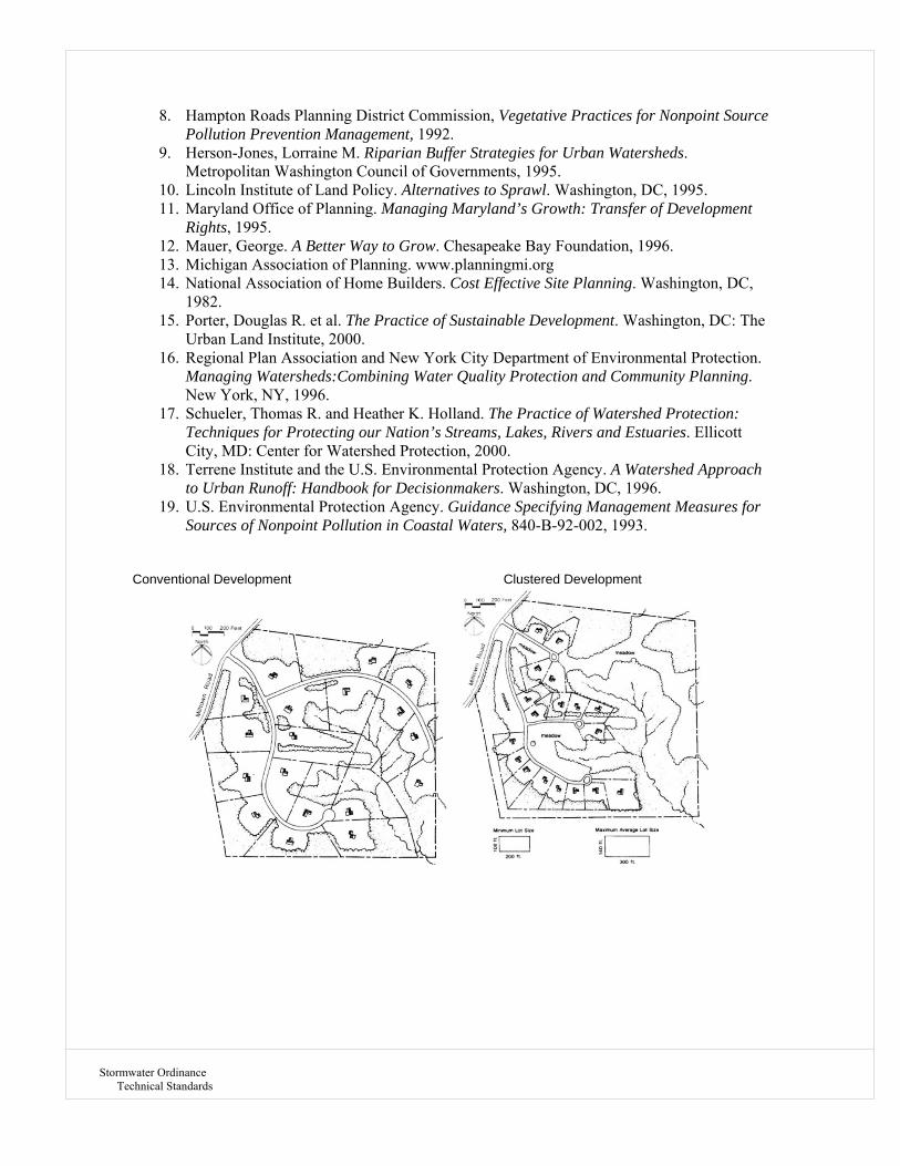
Stormwater Ordinance Technical Standards
8. Hampton Roads Planning District Commission, Vegetative Practices for Nonpoint Source Pollution Prevention Management, 1992.
9. Herson-Jones, Lorraine M. Riparian Buffer Strategies for Urban Watersheds. Metropolitan Washington Council of Governments, 1995.
10. Lincoln Institute of Land Policy. Alternatives to Sprawl. Washington, DC, 1995. 11. Maryland Office of Planning. Managing Maryland’s Growth: Transfer of Development
Rights, 1995. 12. Mauer, George. A Better Way to Grow. Chesapeake Bay Foundation, 1996. 13. Michigan Association of Planning. www.planningmi.org 14. National Association of Home Builders. Cost Effective Site Planning. Washington, DC,
1982. 15. Porter, Douglas R. et al. The Practice of Sustainable Development. Washington, DC: The
Urban Land Institute, 2000. 16. Regional Plan Association and New York City Department of Environmental Protection.
Managing Watersheds:Combining Water Quality Protection and Community Planning. New York, NY, 1996.
17. Schueler, Thomas R. and Heather K. Holland. The Practice of Watershed Protection: Techniques for Protecting our Nation’s Streams, Lakes, Rivers and Estuaries. Ellicott City, MD: Center for Watershed Protection, 2000.
18. Terrene Institute and the U.S. Environmental Protection Agency. A Watershed Approach to Urban Runoff: Handbook for Decisionmakers. Washington, DC, 1996.
19. U.S. Environmental Protection Agency. Guidance Specifying Management Measures for Sources of Nonpoint Pollution in Coastal Waters, 840-B-92-002, 1993.
Conventional Development Clustered Development

Stormwater Ordinance Technical Standards
DESCRIPTION: A key component of LID is to reduce the impacts during development activities such as site grading, removal of existing vegetation, and soil mantle disturbance. This can be achieved through developing a plan to contain disturbed areas and conserve open spaces. Disturbance at a development site can occur through normal construction practices, such as grading, cutting, or filling. Minimizing the total disturbed area by conserving open spaces on the site requires the consideration of multiple BMPs, such as cluster development and identifying and protecting sensitive areas. These BMPs serve to protect area resources by reducing site grading and maintenance required for long-term operation of the site. Minimizing the total disturbed area of a site specifically focuses on how to minimize the grading and overall site disturbance, maximizing conservation of existing native plant communities and the existing soil mantle of a site. If invasive plant species are present in the existing vegetation, proper management of these areas may be required in order for the vegetation to achieve its greatest hydrological potential. Minimize Grading Reduction in grading can be accomplished in several ways, including conforming the site design with existing topography and land surface, where road alignments strive to follow existing contours as much as possible, varying the grade and alignment criteria as necessary to comply with safety limits. Minimize Overall Site Disturbance Site design criteria have evolved in municipalities to ensure that developments meet safety standards (i.e. sight distance and winter icing) as well as certain quality or appearance standards. Roadway design criteria should be flexible in order to optimize the fit for a given parcel and achieve optimal roadway alignment. The avoidance of environmentally sensitive resources, such as important woodlands, may be facilitated through flexible roadway layout. APPLICATION: Minimizing the total disturbed area and conserving open space on a site is best applied in lower density single-family developments, but can also be applied in residential developments of all types including commercial, office park, retail center, and institutional developments. Larger industrial park developments can also benefit from this BMP. However, as site size decreases and density and intensity of development increases, this BMP is uniformly more difficult to apply successfully. At some larger sites where Ultra Urban, Retrofit, or Highway/Road development is occurring, limited application may be feasible. DESIGN CONSIDERATIONS: During the initial conceptual design phase of a land development project, the applicant’s design engineer should provide the following information, ideally through development of a Minimum Disturbance/Open Space Plan: 1. Identify and Avoid Special Value/Sensitive Areas Delineate and avoid environmentally sensitive resources using existing data from appropriate Agencies. 2. Minimize Disturbance at Site Modify road alignments (grades, curvatures, etc.), lots, and building locations to minimize grading, and earthwork as necessary to maintain safety standards and municipal code
BMP LID – 109 OPEN SPACE CONSERVATION

Stormwater Ordinance Technical Standards
requirements. Minimal disturbance design should allow the layout to best fit the land form without significant earthwork, such as locating development in areas of the site that has been previously cleared, if possible. If cut/fill is required, the use of retaining walls is preferable to earthwork. Limits of grading and disturbance should be designated on plan documentation submitted to the municipality for review/approval and should be physically designated at the site during construction via flagging, fencing, etc. In addition, utilizing natural drainage features generally results in less disturbance and requires less revegetation. 3. Minimize Disturbance on Lots to Create More Open Space To decrease disturbance, grading should be limited to roadways and building footprints. Municipalities should establish maximum setbacks from structures, drives, and walks. The Developer should check local requirements before proceeding with the design. These setbacks should be designed to be rigorous but reasonable in terms of current feasible site construction practices. These standards may need to vary with the type of development being proposed and the context of that development (the required disturbance zone around a low density single-family home can be expected to be less than the disturbance necessary for a large commercial structure), given necessity for use of different types of construction equipment and the realities of different site conditions. STORMWATER FUNCTIONS: Volume Any portion of a site that can be maintained in its presettlement state by using this BMP will not contribute increased storm water runoff and will reduce the amount of treatment necessary. In addition, trees protected under this requirement can get a “credit” by receiving a curve number reflecting a woodlot in “good” condition. Peak Rate Runoff from the minimized disturbed area may be excluded from peak rate calculations for rate control, provided that the runoff from the area is not conveyed to and/or through storm water management control structures. If necessary, runoff from the minimized disturbed area should be directed around BMPs and storm water pipes and inlets by means of vegetated swales or low berms that direct flow to natural drainageways. MAINTENANCE: Minimizing site disturbance and conserving open space will result in a reduction of required maintenance of a site in both the short- and long-term. Areas of the site left as intact native plant communities do not typically require replacement with hard surfaces or additional vegetation to retain function. On the other hand, artificial surfaces such as pavement or turf grass require varying levels of maintenance throughout the life of a development. Higher levels of disturbance will also typically require significant maintenance of erosion control measures during the active development of a parcel, thus adding to short-term development costs. While intact natural areas may require small amounts of occasional maintenance (typically through invasive species control) to maintain function, levels of maintenance required for hard surfaces or turf grass will remain static or, in most cases, increase over time. Avoiding disturbance to natural areas benefits the short term developer and the long-term owner by minimizing time and money needed to maintain artificial surfaces. COSTS: The reduced costs of minimized grading and earthwork by conserving open space should benefit the developer. Cost issues include both reduced grading and related earthwork as well as costs involved with site preparation, fine grading, and seeding. Calculation of reduced costs is difficult due to the extreme variation in site factors, (amount of grading, cutting/filling, and haul distances for required trucking,).

Stormwater Ordinance Technical Standards
REFERENCES:
1. Arendt, Randall G. Growing Greener: Conservation by Design. Pennsylvania Department of Conservation and Natural Resources, Governor’s Office of Local Government Services, September 2001.
2. Better Site Design: A Handbook for Changing Development Rules in Your Community. Ellicott City, MD: Center for Watershed Protection, 1998.
3. Coffman, Larry. Low Impact Development Design Strategies: An Integrated Design Approach. EPA 841 B 00 0023. Prince George’s County, MD: Department of Environmental Resources, Programs and Planning, 2000.
4. Conservation Design for Stormwater Management: A Design Approach to Reduce Stormwater Impacts from Land Development. Dover, DE: Delaware Department of Natural Resources and Environment Control, 1997.
5. Guidance Specifying Management Measures for Sources of Nonpoint Pollution in Ocean Waters. Washington, DC: U.S. Environmental Protection Agency report. 840 B 92 002. Section 6217 (g) , January 1993.
6. Minnesota Stormwater Manual Version 1.1. Minnesota Pollution Control Agency, September 2006. www.pca. state.mn.us/water/stormwater/stormwater-manual.html
7. Rooftops to Rivers: A Policy Guide for Decision Makers on How to Use Green Infrastructure to Address Water Quality and Volume Reduction for Communities with Combined Sewer Overflow Issues. Washington, DC: Natural Resources Defense Council, June 2006. www.nrdc.org/water/pollution/rooftops/contents.asp
8. Pennsylvania Stormwater Best Practices Manual. Harrisburg PA: Pennsylvania Department of Environmental Protection, December 2006.
9. Reducing Stormwater Costs through Low Impact Development (LID) Strategies and Practices. PA 841-F-07-006. Washington, DC: U.S. Environmental Protection Agency, December 2007.
10. Site Planning for Urban Stream Protection. Washington, DC: Metropolitan Washington Council of Governments, 1995.
11. Tyne, R. “Bridging the Gap: Developers Can See Green, Economic Benefits of Sustainable Site Design and Low-Impact Development,” Land Development, Spring 2000, pp. 27-31.

Stormwater Ordinance Technical Standards
DESCRIPTION: Protecting sensitive and special value features is the process of identifying and avoiding certain natural features during development. This allows these features to be used for various benefits, including reducing storm water runoff. Protecting sensitive areas can be implemented both at the site level and throughout the community. For prioritization purposes, natural resources and their functions may be weighted according to their functional value. Sensitive areas should be preserved in their natural state to the greatest extent possible and are not the appropriate place to locate storm water infrastructure. Protecting sensitive areas challenges the site planner to inventory and then, to the greatest extent possible, avoid resource sensitive areas at a site, including riparian buffers, wetlands, hydric soils, floodplains, steep slopes, woodlands, valuable habitat zones, and other sensitive resource areas. Development, directed away from sensitive areas, can be held constant, if BMPs such as cluster development are also applied. A major objective of LID is to accommodate development with fewer impacts to the site. If development avoids encroachment upon, disturbance of, and impact to those natural resources which are especially sensitive to land development impacts and/or have special functional value, then low impact development can be achieved. The first step in protecting sensitive areas is for the site planner to define, inventory, and map which resources are especially sensitive and/or have special value at a site proposed for development. Although many sensitive areas are common to all municipalities, they can vary by region. The most detailed inventories are often compiled at the municipal or county level. Preserving open space in multiple development areas throughout a community can ultimately evolve to form a unified open space system, integrating important conservation areas throughout the municipality and beyond. Many communities are undertaking “green infrastructure” planning initiatives to proactively map these systems in order to restore or protect them as development occurs. The objective of these plans is to avoid impacting sensitive areas by: 1) carefully identifying and mapping these resources (resource areas, primary and secondary) from the start of the site planning process, and 2) striving to protect resource areas by defining other portions of the site free of these resources (potential development areas). APPLICATION: Regardless of land use type, protecting sensitive areas is applicable across all types of land development projects, whether residential of varying densities or office park, retail center or industrial and institutional uses. As density and intensity of uses increases, ease of application of this BMP decreases. In such limited cases, it is especially important that sensitive areas be prioritized. DESIGN CONSIDERATIONS: 1. Identify, map, and inventory sensitive areas.
BMP LID – 110 SENSITIVE AREA PROTECTION

Stormwater Ordinance Technical Standards
Mapping a site’s sensitive areas is an important step in preserving them. These features often include wetlands, steep slopes, woodlands, floodplains, and riparian areas. This data may give the community a general idea of the sensitive resources that could be on the site. In addition, the mapping will help the site designer define a potential development area which avoids encroachment upon and disturbance of defined and mapped sensitive areas. The inventory of sensitive areas should also include an assessment of the quality of the existing natural communities. Because plant communities will exist in a variety of states based on historic disturbance and degradation, the quality of the given community needs to be considered in comparison to other similar communities. The quality of a given plant community must also be considered in comparison to other plant communities in the state. 2. Combine mapped natural features into a sensitive resource areas map, prioritizing areas to avoid development. All sensitive resource mapping should be overlain to produce a sensitive areas map. Randall Arendt in Growing Greener acknowledges prioritizing or weighting of sensitive areas by defining them as either Primary Conservation Areas (the most critical – avoid at all costs) or Secondary Conservation Areas (important resources which should be avoided when possible). Mapping the secondary resources of the site is an important step; the community can provide input to determine which features are important for preservation. Additionally, Primary and Secondary Conservation Areas can be defined in different ways, possibly varying with watershed context, (e.g., woodlands in some contexts may be classified as Primary Conservation Areas, rather than secondary). Given the substantial variability in natural resources from one eco-region to another, this flexibility in weighting resource types is especially important. 3. Map potential development areas; prioritize/ weight as necessary. The potential development area should be delineated on the basis of protecting the primary and secondary resources on a site. Like the sensitive areas map, priorities and weightings may be reflected in the potential development area map. If sensitive areas have been prioritized, then weightings of potential development also may be established, varying with lack of degree of sensitivity measured by the resources themselves or overlapping of resources. 4. Municipal regulation The level of regulation imposed on resource areas (primary and secondary) will likely vary by municipality. A municipal ordinance may prohibit and/or otherwise restrict development in primary and secondary resource areas, provided certain legal tests (such as a takings determination) are passed. Additional activities include: 1. Conservation easement – Given to land conservancy or maintained by homeowners association. 2. Requirements in the master deed and bylaws for protection and preservation. 3. Boundary markers at edges of lots to minimize encroachment. 4. Cooperative agreements for stewardship of sensitive areas between homeowners’ associations and local conservation organizations. 5. Tree protection requirements during construction. STORMWATER FUNCTIONS: Any portion of a site that can be maintained in its presettlement state by using this BMP will not contribute increased storm water runoff and will reduce the amount of treatment necessary. Volume Protected sensitive areas are not to be included in the disturbed storm water management area when calculating runoff volume. Any portion of a sensitive area that is mitigated or revegetated/reforested should be included in the disturbed storm water management area, but may be granted credit in accordance with the applicable BMP for native revegetation, riparian buffer restoration, or open space conservation.

Stormwater Ordinance Technical Standards
Peak Rate Runoff from the protected sensitive area may be excluded from peak rate calculations for rate control, provided that the runoff is not conveyed to and/or through storm water management control structures. If necessary, runoff from protected sensitive areas should be directed around BMPs and storm water pipes and inlets by means of vegetated swales or low berms that direct flow to natural drainageways. Water Quality Improvement Water quality is benefited substantially by avoiding negative impacts which otherwise would have resulted from impacts to sensitive areas (e.g., loss of water quality functions from riparian buffers, from wetland reduction, etc.). CONSTRUCTION GUIDELINES: Although protecting sensitive areas happens early in the site plan process, it is equally important that the developer and builder protect these areas during construction. The following guidelines describe good planning practices that will help ensure protection of a few common environmentally sensitive resources during construction. Water Resources • If vegetation needs to be reestablished, plant native species, or use hydroseed and mulch blankets immediately after site disturbance. • Use bioengineering techniques, where possible, to stabilize stream banks. • Block or protect storm drains in areas where construction debris, sediment, or runoff could pollute waterways. • During and after construction activities, sweep the streets to reduce sediment from entering the storm drain system. • Avoid hosing down construction equipment at the site unless the water is contained and does not get into the storm water conveyance system. • Implement spill control and clean-up practices for leaks and spills from fueling, oil, or use of hazardous materials. Use dry clean-up methods (e.g., absorbents) if possible. Never allow a spill to enter the storm water conveyance system. • Avoid mobile fueling of equipment. If mobile fueling is necessary, keep a spill kit on the fueling truck. • Properly dispose of solid waste and trash to prevent it from ending up in our lakes and streams. • When protecting riparian buffer areas, consider the three buffer zones in protection criteria: Zone 1: Also termed the “streamside zone,” begins at the edge of the stream bank of the active channel and extends a minimum distance of 25 feet, measured horizontally on a line perpendicular to the water body. Undisturbed vegetated area aims to protect the physical and ecological integrity of the stream ecosystem. The vegetative target for the streamside zone is undisturbed native woody species with native plants forming canopy, understory, and duff layer; where such forest does not grow naturally, then native vegetative cover appropriate for the area (such as grasses, forbs, or shrubs) is the vegetative target. Zone 2: Also termed the “middle zone,” extends immediately from the outer edge of Zone 1 for a minimum distance of 55 feet. This managed area of native vegetation protects key components of the stream ecosystem and provides distance between upland development and the streamside zone. The vegetative target for the middle zone is either undisturbed or managed native woody species or, in its absence, native vegetative cover of shrubs, grasses, or forbs. Undisturbed forest, as in Zone 1, is strongly encouraged to protect further water quality and the stream ecosystem. Zone 3: Also termed the “outer zone,” it extends a minimum of 20 feet immediately from the outer edge of Zone 2. This zone prevents encroachment into the riparian buffer area, filters runoff from adjacent land, and encourages sheet flow of runoff into the buffer. The vegetative target for the outer zone is native woody and herbaceous vegetation to increase the total width of the buffer; native grasses and forbs are acceptable.
Stormwater Ordinance Technical Standards
Wetlands • Avoid impacts to wetlands whenever possible. If impractical, determine if a wetland permit is needed from the state or local government. (If any permit requirements or wetland regulations conflict with these guidelines, comply with the permit or regulation). • Excavate only what is absolutely necessary to meet engineering requirements. Do not put excavated material in the wetland. (Excavated material could be used in other areas of the site to improve seeding success). • If construction activities need to occur within a wetland, activities should be timed, whenever possible, when the ground is firm and dry. Avoid early spring and fish-spawning periods. • Install flagging or fencing around wetlands to prevent encroachment. • Travel in wetlands should be avoided. Access roads should avoid wetlands whenever possible. Crossing a wetland should be at a single location and at the edge of the wetland, if possible. • Never allow a spill to enter area wetlands. Floodplains • Design the project to maintain natural drainage patterns and runoff rates if possible. • Maintain as much riparian vegetation as possible. If riparian vegetation is damaged or removed during construction, replace with native species. • Use bioengineering techniques to stabilize stream banks. • Keep construction activity away from wildlife crossings and corridors. • Stockpile materials outside of the floodplain and use erosion control techniques. Woodlands • Protect trees on sites with severe design limitations, such as steep slopes and highly erodible soils. • Preserve trees along watercourses to prevent bank erosion, decreased stream temperatures, and to protect aquatic life. • Protect the critical root zone of trees during construction. This is the area directly beneath a tree’s entire canopy. For every inch of diameter of the trunk, protect 1.5 feet of area away from the trunk. (See the Town of Merrillville’s Tree Ordinance) • Avoid trenching utilities through the tree’s critical root zone. • Avoid piling excavated soil around any tree. • Replace trees removed during construction with native trees. • Conduct post-construction monitoring to ensure trees impacted by construction receive appropriate care. General Construction Considerations • Conduct a pre-construction meeting with local community officials, contractors, and subcontractors to discuss natural resource protection. Communicate agreed-upon goals to everyone working on the project. • Insert special requirements addressing sensitive natural areas into plans, specifications, and estimates provided to construction contractors. Note the kinds of activities that are not allowed in sensitive areas. • Confine construction and staging areas to the smallest necessary and clearly mark area boundaries. Confine all construction activity and storage of materials to designated areas. • Install construction flagging or fencing around sensitive areas to prevent encroachment. • Excavate only what is absolutely necessary to meet engineering requirements. Do not put excavated material in sensitive areas. (Excavated material could be used in other areas of the site to improve seeding success.) • Conduct onsite monitoring during construction to ensure sensitive areas are protected as planned. Conduct post-construction monitoring to ensure sensitive areas that were impacted by construction receive appropriate care.

Stormwater Ordinance Technical Standards
MAINTENANCE: The preservation of open space creates maintenance concerns related to who is required to perform the maintenance activities. Legally, the designated open space may be conveyed to the municipality. More likely, ownership of these natural areas will be assumed by homeowners’ associations or simply the specific individual property homeowners where these resources are located. Specific maintenance activities will depend upon the type of vegetation present in the preserved natural area where woodlands require little to no maintenance and open lawn require higher maintenance. COSTS: When development encroaches into sensitive areas, dealing with their special challenges invariably adds to development and construction costs. Sometimes these added costs are substantial, as in the case of working with wetlands or steep slopes. Sometimes costs emerge only in longer-term operation, like encroachment in floodplains. This can translate into added risk of building damage for future owners, as well as health and safety impacts, insurance costs, permitting costs and downstream flooding. If all short- and long-term costs of impacting sensitive areas were quantified and tallied, total real costs of sensitive area encroachment would increase substantially. Conversely, protecting sensitive areas results not only in cost savings, but also in water quality benefits. At the same time, reduction in potential development areas resulting from protecting and conserving sensitive areas can have the effect of altering, even reducing a proposed development program, thereby reducing development yield and profit. To address this, this BMP can be applied in tandem with the cluster development BMP. REFERENCES:
1. Arendt, Randall G. Growing Greener: Conservation by Design. Pennsylvania Department of Conservation and Natural Resources, Natural Lands Trust, Governor’s Office of Local Government Services, September 2001.
2. Coffman, Larry. Low Impact Development Design Strategies: An Integrated Design Approach. EPA 841 B 00 0023. Department of Environmental Resources, Programs and Planning, Prince George’s County, MD, 2000.
3. Delaware Department of Natural Resources and Environment Control. Conservation Design for Stormwater Management: A Design Approach to Reduce Stormwater Impacts from Land Development. Brandywine Conservancy Environmental Management Center, 1997.
4. Effects of Conservation Practices on Water Quantity and Quality, Vols. 1-4. U.S. Department of Agriculture-Soil Conservation Service, Washington, DC, 1988.
5. Minnesota Stormwater Manual, Version 1.1. Minnesota Pollution Control Agency, September 2006. www.pca.state. mn.us/water/stormwater/stormwater-manual.html
6. Natural Resources Defense Council. Rooftops to Rivers: A Policy Guide for Decision Makers on How to Use Green Infrastructure to Address Water Quality and Volume Reduction for Communities with Combined Sewer Overflow Issues. Washington, DC, June 2006. www.nrdc.org/water/pollution/rooftops/contents.asp
7. Stormwater Program Guidance Manual for the Puget Sound Basin. Washington State Department of Ecology, Olympia, WA, 1992.
8. U.S. Environmental Protection Agency. Reducing Stormwater Costs through Low Impact Development (LID) Strategies and Practices. PA 841-F-07-006. Washington, DC, December 2007.

Stormwater Ordinance Technical Standards
DESCRIPTION: LEED is an internationally recognized green building certification system, providing third-party verification that a building or community was designed and built using strategies aimed at improving performance across all the metrics that matter most: energy savings, water efficiency, CO2 emissions reduction, improved indoor environmental quality, and stewardship of resources and sensitivity to their impacts. Developed by the U.S. Green Building Council (USGBC), LEED provides building owners and operators a concise framework for identifying and implementing practical and measurable green building design, construction, operations and maintenance solutions. LEED is flexible enough to apply to all building types – commercial as well as residential. It works throughout the building lifecycle – design and construction, operations and maintenance, tenant fitout, and significant retrofit. And LEED for Neighborhood Development extends the benefits of LEED beyond the building footprint into the neighborhood it serves. APPLICATION: Sustainable Sites Choosing a building's site and managing that site during construction are important considerations for a project’s sustainability. The Sustainable Sites category discourages development on previously undeveloped land; minimizes a building's impact on ecosystems and waterways; encourages regionally appropriate landscaping; rewards smart transportation choices; controls storm water runoff; and reduces erosion, light pollution, heat island effect and construction-related pollution. Water Efficiency Buildings are major users of our potable water supply. The goal of the Water Efficiency credit category is to encourage smarter use of water, inside and out. Water reduction is typically achieved through more efficient appliances, fixtures and fittings inside and water-wise landscaping outside. Energy & Atmosphere According to the U.S. Department of Energy, buildings use 39% of the energy and 74% of the electricity produced each year in the United States. The Energy & Atmosphere category encourages a wide variety of energy strategies: commissioning; energy use monitoring; efficient design and construction; efficient appliances, systems and lighting; the use of renewable and clean sources of energy, generated on-site or off-site; and other innovative strategies. Materials & Resources During both the construction and operations phases, buildings generate a lot of waste and use a lot of materials and resources. This credit category encourages the selection of sustainably grown, harvested, produced and transported products and materials. It promotes the reduction of waste as well as reuse and recycling, and it takes into account the reduction of waste at a product’s source. Indoor Environmental Quality The U.S. Environmental Protection Agency estimates that Americans spend about 90% of their day indoors, where the air quality can be significantly worse than outside. The Indoor
BMP LID – 111 DESIGN FOR LEED CERTIFICATION

Stormwater Ordinance Technical Standards
Environmental Quality credit category promotes strategies that can improve indoor air as well as providing access to natural daylight and views and improving acoustics. Locations & Linkages The LEED for Homes rating system recognizes that much of a home's impact on the environment comes from where it is located and how it fits into its community. The Locations & Linkages credits encourage homes being built away from environmentally sensitive places and instead being built in infill, previously developed and other preferable sites. It rewards homes that are built near already-existing infrastructure, community resources and transit, and it encourages access to open space for walking, physical activity and time spent outdoors. Awareness & Education The LEED for Homes rating system acknowledges that a green home is only truly green if the people who live in it use the green features to maximum effect. The Awareness & Education credits encourage home builders and real estate professionals to provide homeowners, tenants and building managers with the education and tools they need to understand what makes their home green and how to make the most of those features. Innovation in Design The Innovation in Design credit category provides bonus points for projects that use new and innovative technologies and strategies to improve a building’s performance well beyond what is required by other LEED credits or in green building considerations that are not specifically addressed elsewhere in LEED. This credit category also rewards projects for including a LEED Accredited Professional on the team to ensure a holistic, integrated approach to the design and construction phase. Regional Priority USGBC’s regional councils, chapters and affiliates have identified the environmental concerns that are locally most important for every region of the country, and six LEED credits that address those local priorities were selected for each region. A project that earns a regional priority credit will earn one bonus point in addition to any points awarded for that credit. Up to four extra points can be earned in this way. CERTIFICATION: LEED points are awarded on a 100-point scale, and credits are weighted to reflect their potential environmental impacts. Additionally, 10 bonus credits are available, four of which address regionally specific environmental issues. A project must satisfy all prerequisites and earn a minimum number of points to be certified. Think of it like the nutrition label: LEED provides the same kind of important detail about the green aspects of a building that, taken together, deliver higher performance. REFERENCES:
1. The United States Green Building Council. http://www.usgbc.org/

Stormwater Ordinance Technical Standards
DESCRIPTION: Seeding with native grasses, legumes (nitrogen fixing plants) and forbs (broad leaved plants, including wildflowers) is an inexpensive method to quickly cover a site. Native grasses and forbs are adapted to regional conditions of climate and disease and so are relatively low maintenance. Trees and shrubs are more effective than grasses in the removal of nutrients and minimization of water volume. Trees and shrubs contribute to reduced sedimentation and help to reduce erosion. Use of native trees and shrubs is more conducive to restoration of the ecological function of the site. INSTALLATION GUIDELINES: Grasses, Legumes, and Forbes Revegetation, as distinguished from temporary seeding, is used for the long term restoration of a degraded site. Once established, native annuals will reseed themselves, although they may require protection from exotic or invader species. If left unmanaged, natural succession will usually result in the invasion of shrubs and trees. If managed by mowing and/or burning, the native annuals and perennials will persist. Some species of native grasses, legumes, and forbs are relatively easy to grow. These frequently dominate the mixtures used for roadside plantings. Other species may require more intensive management to ensure establishment but will provide a more complete and natural mixture. Seed mixtures can be prepared that will be appropriate for wet, dry, or mesic sites and for a variety of sun exposure regimes. Trees and Shrubs There are a number of revegetation options. The best choice depends upon the site, time frame for completion, financial resources, and available personnel. Revegetation projects can sometimes be best accomplished by planting nothing. The best revegetation, from the standpoint of ecological diversity, and the most economical, may be the project that simply creates the conditions for invasion by native vegetation. Using transplanted stock will hasten the process, and this approach is frequently used. Containers refer to the 1, 5, 10, 15 gal (4, 18, 35, or 50 liter) containment buckets commonly seen in nurseries. Some native plant nurseries make containment stock available in tall narrow containers to encourage development of deep roots. Tubes are a small variation on tall containers, having smaller diameters. Liners are small plastic 6-packs of young rooted plants. Bare root plants may come in bundles if they are small and usually have the roots wrapped in moist absorbant material covered with a plastic wrap to delay drying. Cuttings refer to plants propagated from short sections of branches or limbs, sometimes held temporarily in a mixture of perlite and peat moss prior to planting to promote root formation. CONSIDERATIONS: Grasses, Legumes and Forbes Many suppliers advertise native grass, legume, and forb seed. Check the suppliers reputation before making purchases. Purchase a mixture appropriate for the conditions at the site. Restorationists frequently use hand collected seed to obtain particular species and to ensure that
BMP LID – 112 NATIVE REVEGETATION

Stormwater Ordinance Technical Standards
the stock is native to the area. Processing (pre-soaking, scarification, etc.) of some species is necessary for successful germination. Site Preparation and Planting Plowing or chemical treatment was common in the past to clear the way for restored native species. Recently, interseeding, the practice of sowing native seed in amongst existing grasses, has made this practice unnecessary in many instances. For difficult to remove or aggressive exotics, complete clearing of the site may still be advisable. Many native grasses, legumes, and forbs appear to do as well or better when started without the removal of existing vegetation. Mowing and/or burning, however, may be a necessary step if shading or woody shrubs are a problem at the site. In some habitats and for some species, seed may need to be added for multiple years, since conditions for successful seed set, germination, and survival may not occur each year. Mowing should be repeated whenever competing species reach 1-1.5 ft (304-457 mm) heights. When interseeding, it is best to sow seeds in fall or early spring. Legume seeds are generally inoculated with nitrogen fixing bacteria to enhance growth. Seeds may be broadcast by hand. In large areas, machine seeding can be used. On slopes, hydroseeding may be advisable. After sowing, seeds should be incorporated into the soil using hand raking, harrowing, disking, or drilling. Note that the mechanical techniques require a very light touch to avoid over-burying the seeds. A variety of seed drills is available from different manufacturers. As a rule-of-thumb, seeds should be covered by a layer of soil twice their thickness. An alternative to burying the seeds is to sow in late fall. The objective is to wait until much of the migratory bird population has moved through and then allow the winter weather to work the seed into the earth. When completely clearing a site prior to seeding, it is best to start as early in spring as the ground can be worked. Use a light duty cultivator or harrow to till the ground no deeper than 2 in (51 mm). Tillage should be repeated each time a weed crop reaches 2 in (51 mm) height until the weed seed stock is exhausted (usually every 3 weeks through the spring). Next pack with a water filled roller at least twice over the site, with the second pass at right angles to the first. If broadcasting seed, pack afterwards. If using a specialized seed drill, pack prior to seeding. A layer of mulch will help to reduce water loss and enhance vegetation, but it is difficult to mulch large sites. Trees and Shrubs Plant Stock Container stock is the most expensive approach and has recently fallen into disfavor among restorationists for a variety of reasons. In addition to its cost, container stock tends to take a long time to acclimate to new surroundings and grows more slowly than other plant stocks. Roots in container stock may temporarily confine growth to nursery soil from the pot. Bare root, tube, and cutting plants are forced to adapt more quickly to the new environment. On the other hand, container stock appears to be the best choice for areas where significant traffic and/or other sources of damage are expected to occur. The smaller stocks can be more vulnerable than container stocks to pest, animal, and human damage. If rootless cuttings are used, a large number must be planted to ensure adequate survival. If an objective is to make a rapid change in the micro-climate of the site, use of larger (container) stock may be advantageous. Planting Bare root and tube seedlings can be quickly and easily accomplished by using a mattock, pick, or iron bar. Create a hole using proper tools. Hold the plant so that the roots dangle straight into the hole. Back fill the hole and then tamp to remove air pockets. Container plant stock tends to be relatively heavily and cumbersome. Fifteen gallon (50 liter) containers require two people. The hole should be twice the diameter and depth of the container.

Stormwater Ordinance Technical Standards
When planting trees, prune off encircling or kinked roots as these may strangle the young plant. Plant with the crown (where roots meet stem) just above the ground. Tamp the dirt to remove air pockets. Rootless cutting stock is the most vulnerable to transplant shock and is best used when the plants are dormant (fall and winter). Bare root stock is more vulnerable to transplant shock than is container stock. Bare root trees and shrubs are usually available in the winter and spring from nurseries, with early spring planting most common. Container stock planting times are variable. In the southern and western states, fall plantings are generally more successful. In the northern and mid-western states, spring plantings allow acclimation and root development prior to harsh winters. Some restorationists manage plantings to promote natural succession. Pioneer species, started from cuttings or seeds, are used to provide a quick cover, extensive rooting, and plant structure. This helps to initially stabilize the site. After stabilization, conditions are better for the establishment (planting) of nonpioneer species. Planted stock is not typically fertilized during restorations. Mulching, however, is sometimes done to enhance water retention and provide a measure of protection against erosion and drying. Container plants and larger bare root stock usually cost more than the other options and additional protective measures are frequently used. These may include wire fencing to protect the stem/trunk surface and re-bar supports (using wire in rubber hose) to help support the larger stock. REFERENCES:
1. Riley, A.L. Restoring Streams in Cities. Island Press. 1997; The University of Georgia College of Agricultural & Environmental Sciences Cooperative Extension Service.
2. http://abe.msstate.edu/csd/NRCS-BMPs/pdf/water/erosion/natrevege_trees.pdf

Stormwater Ordinance Technical Standards
DESCRIPTION: Minimize storm water volume by disconnecting roof leaders, impervious roads, and driveways and direct runoff to other BMPs including vegetated areas that infiltrate at the site. Roofs, roads, and driveways account for a large percentage of post-development imperviousness. These surfaces influence storm water quality and runoff volume by facilitating the rapid transport of storm water and collecting pollutants from rainfall, automobile leaks, and additional sources. Disconnecting roof leaders and routing road and driveway runoff from conventional storm water conveyance systems allows runoff to be collected and managed onsite. Runoff can be directed to designed vegetated areas for onsite storage, treatment, and volume control. This is a distributed, low-cost method for reducing runoff volume and improving storm water quality through: • Increasing infiltration and evapotranspiration, • Decreasing storm water runoff volume, and • Increasing storm water time of concentration. The suitability of vegetated swales to receive runoff depends on land use, soil type, imperviousness of the contributing watershed, and dimensions and slope of the vegetated swale system. Use of natural low-lying areas is encouraged; natural drainage courses should be used and preserved. Some ponding of water in areas receiving runoff may occur. It is important to take into account site usage when applying this BMP so that ponding does not unnecessarily interfere with expected site use (including backyard play areas). These areas should be shown on plan documents and protected with easements and deed restrictions. Although this BMP can be applied in a variety of development settings, it will likely be more successful as lot size increases and density decreases. In situations where clustering has not been fully exercised and lots remain relatively large, these lots and the large areas of perviousness make perfect candidates for storm water disconnection. VARIATIONS: Disconnecting storm water can be achieved through identifying the source of runoff and how it will be managed once disconnection occurs. Source Storm water can flow from rooftop areas or from impervious areas such as driveways, walkways, small parking areas, minor roadways, and ancillary outdoor areas such as patios. (Note: Roads and highways, because of their greater runoff generation require Structural BMPs.) Management Practices A common and successful management practice is to direct storm water runoff to areas of existing vegetation. Vegetation can be of varying types, from established meadow to immature to mature woodland. A particular variation to consider is grading (crowning) of drives and minor roadways and eliminating curbing (or provision of curb cuts) so that runoff is allowed to flow in an even and unconcentrated manner onto adjacent vegetated areas.
BMP LID – 113 STORMWATER DISCONNECTIVITY
Stormwater Ordinance Technical Standards
In addition to directing runoff to vegetated areas, runoff may also be discharged to non-vegetated BMPs, such as dry wells, rain barrels, and cisterns for storm water retention and volume reduction. Another management practice includes routing runoff to existing grades and depressions that can be used to capture, store, and treat runoff. An important caveat is that applying this BMP should not prompt grading and disturbing areas which otherwise would not have been disturbed. However, assuming that grading and disturbance cannot be avoided, then subtle adjustments to grading may create additional management/storage opportunities for disconnected runoff. An ideal coupling of BMPs is to minimize the total disturbed area of a site in coordination with storm water disconnection. This not only reduces runoff volumes, peak rates, and pollutant loadings, but also provides multiple decentralized opportunities to receive disconnected flows. APPLICATIONS: Disconnection is ideal for most single-family developments, but can also be applied to many development sites, including larger office parks and retails centers. Industrial developments, with their larger impervious covers and greater runoff volumes, make storm water disconnection a challenge. Even so, there are isolated applications which are beneficial and promote LID objectives. Similarly, Ultra Urban and Highway/Road developments with large flows would be more limited in application. If downspout disconnection is applied as a retrofit, downspouts should be extended away from the basement as many footing drains are attached to the sanitary sewer system. DESIGN CONSIDERATIONS: Careful consideration should be given to the design of vegetated collection areas. Concerns pertaining to basement seepage and water-soaked yards are warranted, with the potential arising for saturated depressed areas and eroded water channels. Proper design and use of bioretention areas, infiltration trenches, and/or dry wells reduces or eliminates the potential for surface ponding and facilitates functioning during cold weather months. Where basements exist, consider the direction of groundwater flow and proximity. Disconnection of small runoff flows can be accomplished in a variety of ways (Prince George’s County Department of Environmental Protection, 1997; Maryland Department of the Environment, 1997; Cahill, 2008). 1. Encourage shallow sheet flow through vegetated areas. 2. Direct roof leader flow into BMPs designed specifically to receive and convey rooftop runoff. 3. Direct flows into stabilized vegetated areas, including on-lot swales and bioretention areas. 4. Rooftop runoff may also be directed to onsite depression storage areas. 5. The entire vegetated “disconnection” area should have a maximum slope of five percent. 6. Runoff should not be directed to vegetated areas if there is reason to believe that pollutant loadings will be elevated. 7. Roof downspouts or curb cuts should be at least 10 feet away from the nearest connected impervious surface to discourage “re-connections.” a. Limit the contributing impervious area to a maximum of 1,000 sq. ft. per discharge point. b. Limit the contributing rooftop area to a maximum of 1,000 sq. ft. per downspout, where pervious area receiving runoff must be at least twice this size. c. For contributing areas greater than 1,000 sq. ft., leveling devices are recommended. 8. The maximum contributing impervious flow path length should be 75 feet. 9. For impervious areas, the length of the disconnection area must be at least the length of the

Stormwater Ordinance Technical Standards
contributing area (a minimum 75 feet for discharges which are concentrated; 25 feet for discharges which are not concentrated). 10. In all cases, flows from roof leaders should not contribute to basement seepage. Storm water runoff from disconnection needs to be monitored to ensure that flows do not become channelized that can result in erosion. Attention must be given to safe overflowing of larger storms, though clearly the more frequent smaller storms are of greatest interest and concern for successful design (use two-year storm for erosion analysis). Make sure flow of water and temporary ponding of water in management areas will not become a problem. STORMWATER FUNCTIONS: Peak Rate and Volume This BMP reduces total volume and peak rates of runoff, as runoff is minimized from centralized storm water management systems at the development site. Disconnection directly reduces volume and peak rates, which reduces the need for structural BMPs. Water Quality Improvement In terms of rooftop disconnection, this BMP has limited water quality benefit because rooftops typically have minimal pollution. In terms of other impervious area runoff sources being disconnected (driveways, walkways, ancillary areas, minor roads), water quality benefits can be significant given their greater pollutant loadings. MAINTENANCE: When disconnecting storm water from rooftops or other impervious surfaces, maintaining the vegetated areas is required, but is limited. If using structural BMPs, such as bio-retention or vegetated swales, follow their specific maintenance activities. Typical maintenance of vegetation includes a biannual health evaluation of the vegetation and subsequent removal of any dead or diseased vegetation plus mulch replenishment, if included in the design. This can be incorporated into regular maintenance of the site landscaping. In some cases, if leaders are directing storm water to lawn depressions, maintenance may be as simple as mowing. COSTS: Storm water disconnection reduces both construction and maintenance costs due to less reliance on traditional storm water management infrastructure. In addition, using existing or planned bioretention areas within a site creates a double usage of these BMPs. REFERENCES:
1. Coffman, Larry. Low Impact Development Design Strategies: An Integrated Design Approach. EPA 841 B 00 0023. Prince George’s County, MD: Department of Environmental Resources, Programs and Planning, 2000.
2. Downspout Disconnection Program, 2006. Portland, OR: Portland Bureau of Environmental Services, 2006.
3. Low-Impact Development Design Strategies: An Integrated Design Approach. Prince George’s County, MD: Maryland Department of Environmental Resources Programs and Planning Division, June 1999.
4. Pennsylvania Stormwater Best Practices Manual. Harrisburg, PA: Pennsylvania Department of Environmental Protection, December 2006.
5. Reducing Stormwater Costs through Low Impact Development (LID) Strategies and Practices. PA 841-F-07-006. Washington, DC: U.S. Environmental Protection Agency, December 2007.
6. Rooftops to Rivers: A Policy Guide for Decision Makers on How to Use Green Infrastructure to Address Water Quality and Volume Reduction for Communities with

Stormwater Ordinance Technical Standards
Combined Sewer Overflow Issues. Washington, DC: Natural Resources Defense Council, June 2006. www.nrdc.org/water/pollution/rooftops/contents.asp
7. Shaver, Earl. Low Impact Design Manual for the Auckland Regional Council. New Zealand: Auckland Regional Council, April 2000.
8. Urbanization and Streams: Studies of Hydrologic Impacts. Washington, DC: U.S. Environmental Protection Agency, 1997.

Stormwater Ordinance Technical Standards
Trees are essential in the removal of nutrients and minimization of water volume runoff. Trees also contribute to reduced sedimentation and help to reduce erosion. With this said, the Town of Merrillville would like to credit developer’s who plant additional trees above what is required in their ordinance. According to the Town of Merrillville’s Subdivision Ordinance the developer is required to provide parkway trees on all proposed streets as called out below: Sec. 19-145. Street signs, landscaping, etc. (c) Street trees shall be planted on both sides of each proposed street except where there are sufficient existing trees present and preserved as determined by the plat officer. Street trees, newly planted, shall be no closer together than forty (40) feet nor further apart than sixty (60) feet and the type of trees shall be determined by the subdivider except that it must be on the approved street tree list, a copy of which can be obtained from the plat officer. Newly planted street trees shall be at least one and one-half (1 1/2) inches in caliper, measured one foot from the ground. Street trees shall be located such that they will not cause serious destruction to street and sidewalk installations. INSTALLATION GUIDELINES: Tree Species Selection List: See most recent version of the Town of Merrillville’s Recommended Tree Selection List and Town of Merrillville Landscape Standards for additional guidance.
SMALL TREES ( ≤ 25’)
Genus Species Common Name Acer ginnala Amur Maple Acer griseum Paperbark Maple Cercis canadensis Eastern Red Bud
Cornus alternifilia Pagoda Dogwood Cornus florida Flowering Dogwood Malus species Crabapples
Prunus species Cherries Quercus prinoides Dwarf Chinquapin Oak Viburnum lentago Nannyberry Viburnum
Viburnum prunifolium Blackhaw Viburnum
MEDIUM TREES (25’ – 40’)
Genus Species Common Name Acer campestre Hedge Maple Amelanchier species Serviceberry Carpinus caroliniana American Hornbeam
Cladrastis kentukea Yellowwood Crataegus coccinea Scarlet Hawthorn Crataegus crusgalli Cockspur Hawthorn
Crataegus phaenopyrum Washington Hawthorn Crataegus viridis Winter Green Hawthorn Eucommia ulmoides Hardy Rubber Tree
Magnolia species Magnolia Ostrya virginiana Hop Hornbeam
BMP LID – 114 ADDITIONAL TREE INSTALLATION
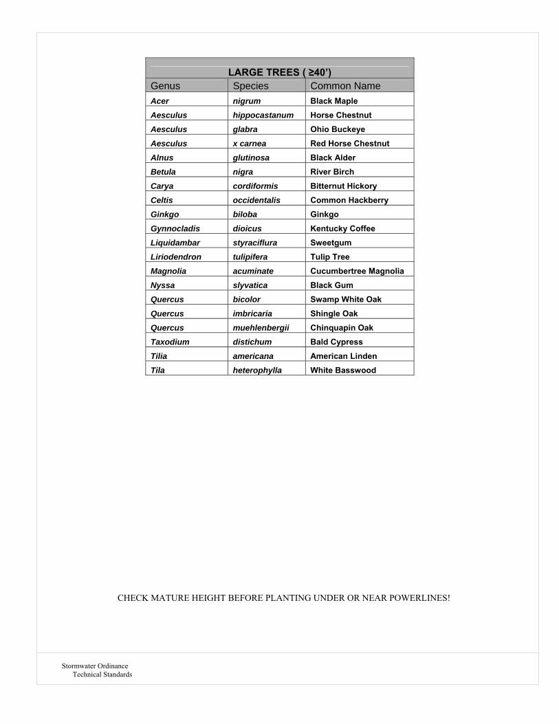
Stormwater Ordinance Technical Standards
CHECK MATURE HEIGHT BEFORE PLANTING UNDER OR NEAR POWERLINES!
LARGE TREES ( ≥40’) Genus Species Common Name Acer nigrum Black Maple Aesculus hippocastanum Horse Chestnut Aesculus glabra Ohio Buckeye
Aesculus x carnea Red Horse Chestnut Alnus glutinosa Black Alder Betula nigra River Birch
Carya cordiformis Bitternut Hickory Celtis occidentalis Common Hackberry Ginkgo biloba Ginkgo
Gynnocladis dioicus Kentucky Coffee Liquidambar styraciflura Sweetgum Liriodendron tulipifera Tulip Tree
Magnolia acuminate Cucumbertree Magnolia Nyssa slyvatica Black Gum Quercus bicolor Swamp White Oak
Quercus imbricaria Shingle Oak Quercus muehlenbergii Chinquapin Oak Taxodium distichum Bald Cypress
Tilia americana American Linden Tila heterophylla White Basswood

Stormwater Ordinance Technical Standards
REFERENCES:
1. Indiana Community Tree Selection Guide, 2009, Recommendations by Indiana’s City Forester’s and IDNR, Community and Urban Forestry pgs 1 & 12.
2. Sec. 19-145. Street signs, landscaping, etc. , The Town of Merrillville Subdivision Ordinance.
3. Tree Species Selection List, 2009, The Town of Merrillville Tree Ordinance.
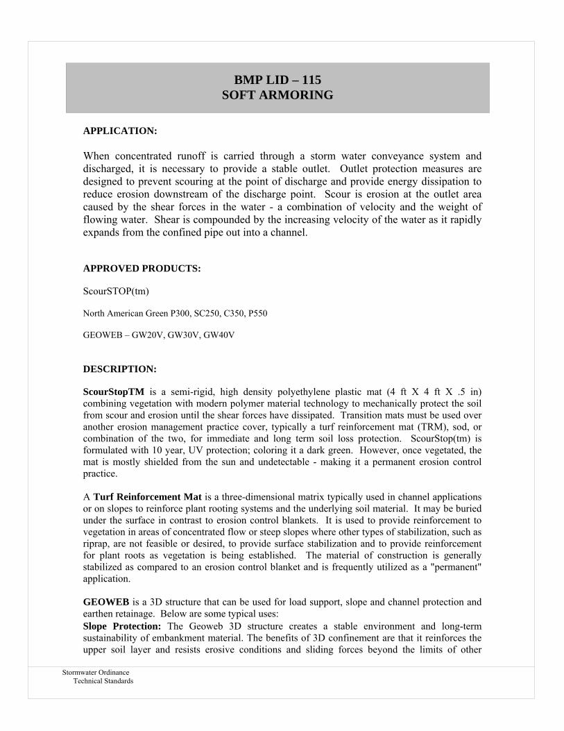
Stormwater Ordinance Technical Standards
APPLICATION:
When concentrated runoff is carried through a storm water conveyance system and discharged, it is necessary to provide a stable outlet. Outlet protection measures are designed to prevent scouring at the point of discharge and provide energy dissipation to reduce erosion downstream of the discharge point. Scour is erosion at the outlet area caused by the shear forces in the water - a combination of velocity and the weight of flowing water. Shear is compounded by the increasing velocity of the water as it rapidly expands from the confined pipe out into a channel.
APPROVED PRODUCTS:
ScourSTOP(tm)
North American Green P300, SC250, C350, P550
GEOWEB – GW20V, GW30V, GW40V
DESCRIPTION:
ScourStopTM is a semi-rigid, high density polyethylene plastic mat (4 ft X 4 ft X .5 in) combining vegetation with modern polymer material technology to mechanically protect the soil from scour and erosion until the shear forces have dissipated. Transition mats must be used over another erosion management practice cover, typically a turf reinforcement mat (TRM), sod, or combination of the two, for immediate and long term soil loss protection. ScourStop(tm) is formulated with 10 year, UV protection; coloring it a dark green. However, once vegetated, the mat is mostly shielded from the sun and undetectable - making it a permanent erosion control practice. A Turf Reinforcement Mat is a three-dimensional matrix typically used in channel applications or on slopes to reinforce plant rooting systems and the underlying soil material. It may be buried under the surface in contrast to erosion control blankets. It is used to provide reinforcement to vegetation in areas of concentrated flow or steep slopes where other types of stabilization, such as riprap, are not feasible or desired, to provide surface stabilization and to provide reinforcement for plant roots as vegetation is being established. The material of construction is generally stabilized as compared to an erosion control blanket and is frequently utilized as a "permanent" application. GEOWEB is a 3D structure that can be used for load support, slope and channel protection and earthen retainage. Below are some typical uses: Slope Protection: The Geoweb 3D structure creates a stable environment and long-term sustainability of embankment material. The benefits of 3D confinement are that it reinforces the upper soil layer and resists erosive conditions and sliding forces beyond the limits of other
BMP LID – 115 SOFT ARMORING

Stormwater Ordinance Technical Standards
surface protection systems. It's an ideal long-term solution for sustainable vegetation, permeable aggregate, hard-armored concrete or protecting geomembranes. You'll also be able to reduce land space requirements and costs because confined infill allows slopes to be designed steeper than when unconfined.
Channel Protection: The Geoweb system is a proven solution for ensuring stability and protection to channels exposed to erosive conditions of all types. Whether low or high flows, intermittent or continuous, the Geoweb system can be designed to withstand even the highest velocities with appropriate infill materials. Research substantiates the effectiveness of the vegetated Geoweb/TRM system for sustaining velocities as high as 30 ft/sec (9m/sec). That means vegetation can replace costly rip rap in drainage ditches and stormwater channels.
Vegetated Retaining Walls: The multi-layered Geoweb system creates economical and structurally-sound retaining walls that meet all design requirements and desired aesthetics through a terraced vegetated face. Typical wall structures include steepened slopes, geocomposite retaining walls, gravity walls and multi-layered channel systems. Contractors prefer Geoweb retaining walls because installation is quicker and handling of light-weight sections causes less stress on workers compared to block wall systems. INSTALLATION:
SCOURSTOP- See http://www.scourstop.com/ease-of-installation.php for manufacturer's installation instructions. TURF REINFORCEMENT MATS- See http://www.nagreen.com/ for specific installation instructions for the proposed model on the plans to be used. GEOWEB- See http://www.prestogeo.com/geoweb for specific installation instructions for each type of application.
MAINTENANCE:
� Inspect after each rainfall event during establishment of vegetation. Inspect yearly after vegetation established.
� Repair / revegetate as needed.
SPECIFICATIONS:
See http://www.scourstop.com/resources.php for the manufacturer's design specifications.
See http://www.nagreen.com/ for specifications of the specific model proposed on the plans.
See http://www.prestogeo.com/ for specifications of the specific application and sizes.
LIMITATIONS: � Certain armoring should be used in conjunction with other erosion practices. � Each application must not exceed the maximum shear stress created by water flow
specified by the manufacturer when used in concentrated flow areas.
� The material of construction should have an appropriate life expectancy for the application.

Stormwater Ordinance Technical Standards
REFERENCES:
1. The Indiana Storm Water Quality Design Manual, Planning and Specification Guide for Effective Erosion and Sediment Control and Post-Construction Water Quality. Published by the Indiana Department of Environmental Management.
2. http://www.scourstop.com/
3. http://www.nagreen.com/
4. http://www.prestogeo.com/