The Structural Response of a Rail Accelerator rail accelerator imparts high velocity to a structural...
20
_/_oA rm-yjy_,/ NASA Technical Memorandum 83491 NASA-TM-83491 19830027141 ! The Structural Response of a Rail Accelerator S. Y. Wang Lewis Research Center Cleveland, Ohio , _'2 _ iq84 Jh_,NGLEYRESEAt. " •., __-i,_ r £R LISR.t, Ry, NASA |j. _, r-'r,_l VIRGINIA Prepared for the Second Symposium on Electromagnetic Launch Technology sponsored by the Institute of Electrical and Electronics Engineers Boston, Massachusetts, October 10-14, 1983 https://ntrs.nasa.gov/search.jsp?R=19830027141 2018-06-02T10:20:28+00:00Z
Transcript of The Structural Response of a Rail Accelerator rail accelerator imparts high velocity to a structural...
_/_oArm-yjy_,/
NASA Technical Memorandum 83491 NASA-TM-83491 19830027141
!
The Structural Response of aRail Accelerator
S. Y. WangLewis Research CenterCleveland, Ohio
, _'2_ iq84
Jh_,NGLEYRESEAt. " •., __-i,_r £RLISR.t, Ry, NASA
|j. _, r-'r,_l VIRGINIA
Prepared for theSecond Symposium on Electromagnetic Launch Technologysponsored by the Institute of Electrical and Electronics EngineersBoston, Massachusetts, October 10-14, 1983
https://ntrs.nasa.gov/search.jsp?R=19830027141 2018-06-02T10:20:28+00:00Z


THE STRUCTURALRESPONSEOF A RAIL ACCELERATOR
S. Y. Wang
National Aeronautics and Space AdministrationLewis Research Center
Cleveland, Ohio 44135
Abstract transient deflections of the rail in three dimensionsas well as the propagation of the stress wave.
The transient response of a 0.4 by 0.6 cm rectan-gular bore rail accelerator was analyzed using a The primary purpose of this paper is to predictthree-dimensional finite-element code. Results are the transient rail and side-wall displacements of apresented for the case of a 210-kA current input and 0.4 cm by 0.6 cm rectangular bore, one meter long rail5-cm arc length. Typically, the copper rail deflected accelerator using the three-dimensional finite-elementto a peak value of 0.08 mm in compression and then code MARCon CRAY[IBM computers. Both rail and sideoscillated at an amplitude of 0.02 mm. Simultaneously wall deflections are estimated by applying a pulsedthe insu|ating side wall of glass fabric base, epoxy plasma loading on both the side wall and the rail andresin laminate (G-IO) was compressed to a peak value a magnetic loading on the rail behind the projectile.of 0.13 mm and rebounded to a steady state in A secondary purpose is to calculate the stress of theextension. Projectile pinch or blow-by due to the supporting materials, including a glass fabric base,rail (or side-wall) extension or compression, respec- epoxy resin laminate (G-IO), a polycarbonate resintively, can be identified by examining the time history (Lexan), and a pheno|ic resin.of the rail (or side-wall} displacement. For the casepresented, the effect of blow-by was most significant Results are presented using the Newmark directat the side wall characterized by mm-size displacement integration method for a typical case of 210-kAin compression, current input, with a 5-cm plasma arc length at an
instantaneous velocity of 2.5 km[s. A modal methodDynamic stress calculations indicate that the using I0 modes is also used for comparison.
G-IO supporting material behind the rail is subjectedto over 21MPa - at which the G-IO could fail if the Analytical Procedureslaminate was not carefully oriented. Results for apolycarbonate resin (Lexan) side wall snow much larger When a material is subjected to a significantdisplacements and stresses than for G-tO. Therefore dynamic loading, disturbances are propagated throughthe tradeoff between the transparency of Lexan and the the body as stress waves. Deformations resulting frommechanical strength of G-IO for side-wall materia| is the impulsive loading will be highly localized withinobvious, the region influenced by the stress wave, while the
global structure effect is small. For this case wide-Displacement calculations from the modal method spectrum frequencies are excited; however, the high-
are smaller than the results from the direct integra- frequency modes usually dominate throughout the time oftion method by almost an order of magnitude, because interest. [5]the high-frequency effect is neglected. However, thiseffect is significant and dominating for a highly- Finite-element Codeimpulsive, wave-propagation problem such as the railaccelerator structure. The three-dimensional finite-element computer
code, MARCL6], is available in both modal method andIntroduction direct integrating method. The former allows a choice
of 10 modes and is generally good for low-frequencyA rail accelerator imparts high velocity to a structural dynamic problems. The latter is appropriate
projectile through the application of large impulsive for high-loading, wave-propagation problems such asforces of short duration. For the case of a plasma the rail accelerator. The direct Newmark integrationarmature, the rail accelerator structure is dynamically method was selected for the analysis, and the lO-modestressed by the plasma pressure and magnetic forces modal method was used for comparison purposes.immediately behind the projectile. [l] The impulsiveloading causes stress waves to propagate through the The finite element mesh plot was generated andstructure inducing responses in the materials at the shown in Fig. 1(a). Only a quadrant of the rail ac-wave speed. Displacements of the rails and insulating celerator, of Figs. l(b) and (c), is needed because ofside walls ahead of the projectile may hinder the per- two planes of symmetry. The element used is a 8-node,formance of the accelerator [2] due to a combination isoparametric, three-dimensional hexahedron block.of two effects: pinch and blow-by. The former occurs The mesh model consists of 300 elements and 504 nodes.when the rails or side walls pinch into the projectile A typical run on the CRAY-IS uses about 18 minutes (inand frictional interaction intensifies; the latter CPU). All the outputs and post plots are then trans-occurs when the clearance between the projectile and ferred to a front computer the IBM 3033.the rails or side wails opens allowing the plasma toblow by the projectile. These effects can be detri- For the cases studied, the materials used for themental if the design of the rail and supporting rail accelerator were held within the elastic limits.structures are insufficient to handle the intensive Any plastic distortion or non-linear effect is unde-pulse loading of hundreds of megapascals, sirable. Furthermore, the secondary effect of damping
is not included in this report which represent theNumerical analysis can be used to estimate the upper bound values of both displacement and stress.
structural response of the rail accelerators. Forsome rail geometries, one or two-dimensional analyses Input Conditions[3,4] have been applied to estimate the maximum raildeflections and the relative effects of different A rail accelerator one meter long with a bore ofstructural or material properties. However, it is 0.4 by 0.6 cm was simulated. Rails are made of copper,desirable to use a three-dimensional transient program and side-wall and supporting structures are made ofto model a rail accelerator structure to visualize the G-lO/Lexan and phenolic resin. Their properties are
1

listed in Table I. A high current plasma armature was G-IO backing material behind the rail, and the sec-produced to acceleratethe projectilebetween the tional stress contours of case P41.rails.
Figure 3 shows the rail displacementsat theReferringto Fig. 1, the projectileis set to a breech end (nodes 1 and 2) and the muzzle end (nodes 20
startingposition (referencenodal point 2) and is and 21}. Each nodal point has a similar responseacceleratedby the arc plasma covering bore walls of characterizedby a pulse due to the impulsiveloadingelement numbers 1 and 241 along the x-directionbetween and then approachinga quasi-steadyvalue. Figure 4the rail, all the way through to the muzzle end (refer- shows that the typical response of a single node 3,ence nodal point 21). 5-cm downstreamof the projectile'sstarting position
which is another 5 cm from the breech end. It alsoLoading Conditions shows the peak displacementreaches 0.06 mm of
compression and oscillates,with a period of 30 usecLoading inputs include both arc plasma pressure within 0.01 to 0.03 mm range. The instantaneous
(Po} and rail magnetic pressure (Pr)- Po is position of the projectilecorrespondsto a 40 psecacting on the back of the projectileof An area (Ap) time scale in Fig. 4, where a compressionof 0.03 mmand is propotionalto the Lorentz force (Fp). Fp indicatespossible blow-by which means the plasmais obtained from the input current (1) and the induct- leaks through the clearance to the front of theance gradient (L') of the rail: projectile. The actual processes of blow-by or pinch
are complicatedbecause of their high-speed,nigh-F temperature, and dynamic features. However the trans-
p =P_ L'I2 ient displacementcan be used as a critical parameterp Ap - 2 hp S to assess the possibilityof blow-by or pinch. Crite-
rion for the parametermay be differentfor different
where hp is the rail height, and S is the distance acceleratorsunder various operatingconditions.between-therails. Pr is equal to the magneticforce (Fr) per unit rail area (Ar) and is acting Correspondingside-walldisplacementsare plottedon the rail only: in Fig. 5, at the breech end (nodes421 and 422) and
at the muzzle end (nodes 440 and 441). Peak deflec-
Fr _ 12 . dL' tions of between 0.07-0.15mm are obtained along thePr - Ar 2 np h d-_ one meter length of the accelerator,while the quasi-steady deflectionsare under extension (indicatedby
minus values). Figure 6 shows the displacementsofwhere h is the arc plasma height, and dL'/d(S/h)is the node 423. At the current projectileposition 5-cminductance gradient calculated for this geometry. [7J downstr6am (corresponding to 40 _sec), a compression
of 0.07 mm indicates that the effect of blow-by may beIt is assumed that PD is uniformly distributed larger than that on the rail. However, the pinch
behind the projectile within an arc length (La). The effect Seems to be negligible on the projectileacting period of time (at) of Pp on a specific ele- because the displacements are mostly positive at thatment wall is then La/Vm; where Vm is the instan- instant.taneous speed of the arc traveling through the bore,and La can be estimated by combining available The transient stress calculation for G-tO elementmeasured values L8,9] and the scaling laws. [I0] 83 (which is under element 23 in Fig. l(a)) exhibits a
typical variation during the time of interest as shownTypical values used for the calculations are in Fig. 7. This element behind the rail, at 5-cm
listed in Table II. downstream of the projectile's starting position, hasa stress wave form similar to these of displacement
For illustration, the transient pressure inputs response, peaked at 22 MPa and approached quasi-steadyare plotted in Fig. 2 for rail elements i through 4, value of 8 MPa. If the G-IO laminates are oriented inand also for side-wall elements 241 through 244. Where the weakest direction at which the yield strength isa flat-topped pulse of 20 wsec is assumed for Pp of approximately 7 MPa, failure can occur. [12] Stress450 MPa and a constant Pr is 240 MPa. With known contours are plotted at a section cut through the railarc length and speed, only the arc shape is assumed and its G-IO backing material (elements 61 through i00for the transient loading inputs, and 241 through 260}, for each I00 _sec time period.
The traveling characteristic of the stress wave can beDifferent pulse shapes of inertia loading and re- seen from Fig. 8 where the stress concentration reaches
sponses have been well investigated. [ii] The square 410 MPa on the rail for most of the time while peakedwave renders the maximum response, by an amplification at 700 MPa at the end due to rebounding at the muzzlefactor of two, as compared to other shapes: sinus- end.oidal, triangular,sudden-rise,or sudden-fall. The
fiat-topped shape pulse assumed in the paper should SecondaryCase (N411give more conservativevalues of displacement,althoughthe actual shape of loading may be quite complicated. It can be seen from Fig. 9 that the deflection
reaches 0.8 mm using Lexan as the side-wallmaterial.Results and Discussions This displacementis about an order of magnitude larger
than the G-IO case shown in Fig. 6, and the effect ofThe primary case (P41) is calculatedusing G-tO blow-by will be significant. The use of Lexan at high
as the side-wallinsulatorand applying the direct current (210-kA1 seems to be unfeasible. The tradeintegrationmethod. Two secondarycases are included off between the transparencyand the operatingcur-for the relative comparisonof using transparentLexan rent, or the mechanical strength,is thus obvious.as the side-wallmaterial (Case N41) and of applyingthe modal method with ten modes (Case Q41). SecondaryCase (Q411
The Primary Case (P41} For the purpose of demonstratingthe differencebetween the applicationof numericalmethods, the same
Time history results are presentedfor both rail input conditions of the primary case is calculatedbyand side-walldisplacements,the element stress of using the modal method. As shown in Fig. 10, rail
2

displacements are much smaller. Oil the other hand 4. R.S. Hawke, and J.K. Scudder, "Magnetic Propulsionperiods are larger when compared with Fig. 4. The Railguns: Their Design and Capabilities", UCRL-82677,reason for these differences is the modal method does Lawrence Livermore Lab., 1979.not include enough modes so that the dominating effectsof high frequencies of the wave are neglected. On the 5. J.A. Zukas, et al., Impact Dynamics, John Wiley aother hand, the direct integration method is appro- Sons, Inc. 1982.priate for the highly impulsive, wave-propagationproblem such as the rail accelerator. 6. "N_ARCGeneral Purpose Finite Element Program,"
User Manual Vol. A-E, MARCAnalysis Research Corp.Concludin 9 Remarks Palo Alto, CA., 1982.
The response of a rail accelerator structure to 7. J.F. Kerrisk, "Current Distribution and Inductancean impulsive loading can be predicted by a three- Calculations for Rail-Gun Conductors," LA-9092-MS Losdimensional, finite-element code - MARCusing the Alamos National Lab., Nov. 1981.direct integration method. The effects of blow-by orpinch are shown by rail or side-wall displacements. 8. J.V. Parker, D.R. Peterson, C.E. Cummings, andMechanical limits are also discussed to the first order C.M. Fowler, "Measurement of Railgun Arcby calculating the dynamic stress values. Relative Characteristics,"LA-UR82-2177, Los Alamos Nationalmerits of different materials or geometry can readily Lab., Nov. 1982.be assessed.
9. K.A. Jamison, and H.S. Burden, "Arc Armature
Diagnostic Experiments Un An ElectromagneticGun,"References ARRADCOM Technical Conference Paper, Ballistic
Research Lab., July 1982.i. E.E. Rice, L.A. Miller, and R.W. Earhart,
"Preliminary Feasibility Assessment for Earth-to-Space lO. J.D. Powel] and J.H. Batteh, "Plasma dynamics ofElectromagnetic (Railgun) Launchers," NASA CR-161886, an arc-driven, electromagnetic, projectileBattelle Columbus Lab., June 30, 1982. accelerator," Ballistic Research Lab., J. Appl. Phys.,
Vol. 52, pp. 2717-2730, April 1981.2. D.R. Peterson, et al., Monthly Letter, Los Alamos
National Lab., Feb. 12, 1982. If. M. Kornhauser, Structural Effect of Impact.Baltimore: Spartan Books, 1964.
3. R.F. Davidson, Los Alamos National Lab., Private
Communication, Dec. 1982. 12. D.P. Bauer, T.J. McCormick, and J.P. Barber,"Electric Rail Launcher System Design and TestEvaluation," IAP-TR-82-6. IAP Research, Inc. Nov. 1982.

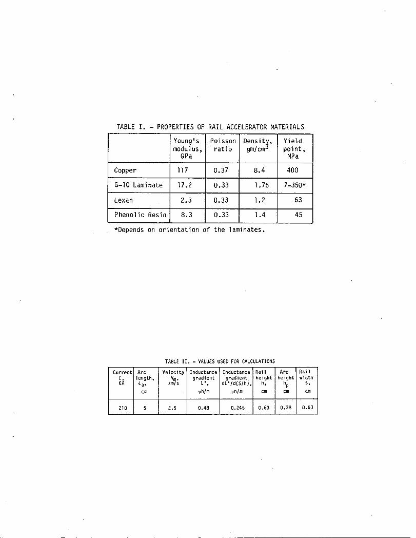
TABLEI. - PROPERTIESOF RAIL ACCELERATORMATERIALS
Young's Poisson Density, Yieldmodulus, ratio gm/cm° point,
GPa MPa
Copper 117 0.37 8.4 400
G-IO Laminate 17.2 0.33 1.75 7-350*
Lexan 2.3 0.33 1.2 63
Phenolic Resin 8.3 0.33 1.4 45
*Depends on orlentation of the laminates.
TABLE II. - VALUES USED FOR CALCULATIONS
Current Arc Ve]ocity Inductance Inductance Rail Arc RailI, length, V , gradient gradient height height width
KA La, km_s L', dL'Id(S/h), n, hp s,cm _h/m un/m cm cm cm
210 5 2.5 0.48 0.245 0.63 0.38 0.63

rBREECHEND422---_t
1 43 85 127422-
NOTE:(I)DIMENSIONSINCENTIMETERS.
PROJECTILEq (2)CIRCLEDNUMBERSAREELEMENTS;STARTING NUMBERSWITHOUTCIRCLESAREPOSITION NODES.
100
PHENOLICRESIN
G-IO/LEXANSI
CC
0.19
lO5_-_AqK/////////,*./////.// T
13
MUZZLEENDJ G" PHENOLICRESIN
3 COPPERJ/ ///
Z G-IO/IEXANJ/ _ 0 3.05
504 _ l 420
II0.31
(a)A_eshplotoftheO.4xO.6cmrailaccelerator.
FigureI.

SYMMETRICA QUADRANTBETWEENPLANEB TWOSYMMETRICPLANES
IS USEDFORMODELING
@SS---.
(_ SYMMETRICG-lO--- PLANBA
@ @o-1oORLEXANCu--
'-(!)PHENOLICRESIN
, (b)Railacceleratorcrosssection.
Figure1. - Continued.

fSWITCH ENERGY
STORAGE JECTILE
i TTT/
t PLASMA "/'" // ,/ARNV_TURE_ /" .,/ // /
,/
-, /DETAILA ..I,
PROJECTILE
**/Jf
R RAIL
I /B /
\ J /X-RAILGUNSUPPORT /" //" DETAILA
I /
COPPER /RAILS
(c)Railaccelerator(gun).
Figure1. - Concluded.

ELEMENT4 ELEMENT244
350_ _
o I I I IELEMENT3 ELEMENT243700 --
,,," ELEMENT2 ELEMENT242
n
35O
o I I I I700 +Pp ELEMENT1 b ELEMENT241
Pp
350 PrI I I I I0 40 80 120 0 40 80 120
TIME,ps
Figure2. - Transientprofilesofpressureloadingfor thefirst four elementsof boththe rail (1-4)andsidewall(241-244).

.100 -- NODE END
I-DZ}2-DZ BREECH20-DZ|21-DZI MUZZLE
• 075 --
!
-.o25 I I I I I0 .1 .2 .3 .4 .5
TINE,ms
Figure3. - Raildisplacementsatbreechandmuzzleends.

•075
PROJECTILEPOSITION .15 -- NODE END
421-DYI422-DYJ BREECH
050 NODE3-DZ I0-- 440-DYIE " " ------ 441-DY_ MUZZLEE
z',' E. 05
_ z
r_ 1.1.1
,,-I•025 o. 0
L/3
-.05A COMPRESSIONOF0.03mmINDICATESPOSSIBLEBLOW-BY: THEPLASMALEAKSTOTHEFRONTOFTHEPROJECTILE
I I I I -.lo I I I I I0 .I .2 .3 .4 .5 0 .I .2 .3 .4 .5
TIME,ms TIME,ms
Figure4.-Raildisplacement5-cmdownstream. Figure5.-Side-walldisplacementsatbreechlmuzzleends.

•15 PROJECTILEPOSITION
I
-.o5 I I I0 .1 .2 .3 .4 .5
TIME,ms
Figure6. - Side-wallG-IOdisplacement5-cmdownstream.
25
20 ELEMENT83STRESS
I I I I I0 .1 .2 .3 .4 .5
TIME,ms
Figure7. - Stressin G-IObackingmaterial5-cmdownstream.

CURVE STRESS,FOR _-'__.S _'-"T-400psMPa XZ-LAYERSTRESSATT=400ps(P41)
I 902 3003 .50O4 100 ,°-;-;-.-;-;-.-.":.-.-.'-;"-,".'-7-.7-;'--,'-.'-.'--,•
::.--:-:::::::-:._::::::::-._:;:::::::::::
XZ-LAYERSTRESSATT -300ps(P41)
CURVE STRESS,FOR ................................................"'""- - -_-_-_-_- _'__' L__./._,:..... ".J.,'.,'.,'.+" .....
T " 100-300ps ::::::::::::::::::::::::::::::::::::::::::::::::::MPa XZ-LAYERSTRESSATT-200ps(P41)
I 50 /- G-10BACKING2 170 .i...................................................-..--..---COPPERRAIL
3 201:) '_-'._- '_-::_-,':-:'.-_:,::.::,:-:,.".:.:.'.-.:,':.:,::-;:'.:,:_'.'_:,:'.:,:_':,}':...'_"'-- G-10SIDE-WALL4 410 SLEEVE
XZ-LAYERSTRESSATT-100ps(P41)
_2
Figure8. - Transient stress contours forcopperrait lelements61-801,G-10backino(elements81-100),andG-10sidingletements2,tl-260).

-.25 I I I I -._5i I I I I I0 .I .2 .3 .4 .5 0 .I .2 .3 .4 .5
TIME,ms TIME,ms
Figure9.-Displacements.5-cmdownstreamusinglexan. Figure10.-Displacements5-cmdownstreammodalmethod.


1. Report No. 2. Government Accession No. 3. Reciplent's Catalog No.
NASATM-834914. Title and Subtitle 5. Report Date
The Structural Response of a Rail Accelerator 6 PerformlngOrganlzationCode506-55-22
7. Author(s) 8. Performing Organization Report No.
E-1820
S. Y. Wang lO.WorkUnltNo.
9. Performing Organization Name and Address11. Contract or Grant No.
National Aeronautics and Space AdministrationLewis Research CenterCleveland, Ohio 44135 13. Type of Report and Period Covered
12. Sponsoring Agency Name and Address Technical Memorandum
National Aeronautics and Space Administration 14.SponsoringAgency CodeWashington, D.C. 20546
15, Supplementary Notes
Prepared for the Second Symposium on Electromagnetic Launch Technology, sponsoredby the Institute of Electrical and Electronics Engineers, Boston, Massachusetts,October 10-14, 1983.
16. Abstract
The transient response of a 0.4 by 0.6 cm rectangular bore rail accelerator was analyzed usinga three-dimensional finite-element code. Results are presented for the case of a 2lO-kA currentinput and 5-cm arc length. Typically, the copper rail deflected to a peak value of 0.08 mmin com-pression and then oscillated at an amplitude of 0.02 n_n. Simultaneously the insulating side wall ofglass fabric base, epoxy resin laminate (G-IO) was compressed to a peak value of 0.13 mmand re-bounded to a steady state in extension. Projectile pinch or blow-by due to the rail (or side-wall)extension or compression, respectively, can be identified by examining the time history of the rai](or side-wall) displacement. For the case presented, the effect of blow-by was most significant atthe side wall characterized by mm-size displacement in compression. Dynamic stress calculationsindicate that the G-IO supporting material behind the rail is subjected to over 21MPa - at whichthe G-]O could fail if the laminate was not carefully oriented. Results for a polycarbonate resin(Lexan) side wall show much larger displacements and stresses than for G-]O. Therefore the tradeoffbetween the transparency of Lexan and the mechanical strength of G-]O for side-wall material is ob-vious, Displacement calculations from the modal method are smaller than the results from the directintegration method by almost an order of magnitude, because the high-frequency effect is neglected,However, this effect is significant and dominating for a highly-impulsive, wave-propagation problemsuch as the rail accelerator structure.
17. Key Words (Suggested by Author(s)) 18. Distribution Statement
Propulsion Unclassified- unlimitedRail gun STAR Category39Structuredynamics
19. Security Classlf. (of this report) 20. Security Classlf. (of this page) 21. No. of pages 22. Price*
Uncl assi fied Uncl ass i fi ed
*For sale by the National Technical Information Service, Springfield, Virginia 22161


LU
IIliiiiii[iiiiiiiriiiiirII •I!_------_ational Aeronautics and SPECIALFOURT_ CLAS_MAIL 3 1176 00513 2981
Space Administration BOC'j..._._ ;_,IllllWashington, D.C. __.....-'20546
Official Business
Penalty for Private Use, $300 Postageand Fees PaidNational Aeronautics andSPace AdministrationNASA451
NASA POSTMASTER: If Undeliverahle (Section I 5_Postal Manual) 1)_ Not Return