The Fracture Behaviour of Girth Welds in High Strength High Yield to Tensile Ratio Linepipe Steels 1

•
! V. ( of {U^nihmra
and the Strength of Ainmittum Welds
•irvrv.i-vf?
1 CJ .INOIS.'UUVKAJtY' N

THE UNIVERSITY
OF ILLINOIS
LIBRARY
Ef 6


THE WKLDING OF ALUMINUMAND
THE STRENGTH OF ALUMINUM WEEDS
BY
ARMIN ELMENDORF
THESISFOR THE
DEGREE OF BACHELOR OF SCIENCE
IN
MECHANICAL ENGINEERING
COLLEGE OF ENGINEERING
UNIVERSITY OF ILLINOIS
1914

Digitized by the Internet Archive
in 2014
http://archive.org/details/weldingofaluminuOOelme

ETffe
UNIVERSITY OF ILLINOIS
Hay 28 191A
THIS IS TO CERTIFY THAT THE THESIS PREPARED UNDER MY SUPERVISION BY
Armin Elmendorf
ENTITLED The ;7eia inS of Aluminum end the Strength of
Aluminum Welds
IS APPROVED BY ME AS FULFILLING THIS PART OF THE REQUIREMENTS FOR THE
Bachelor of Science in Llechanical EngineeringDEGREE OF
Instructor in Charge
APPROVED: L \~^L ^^^C^-^^^
HEAD OF DEPARTMENT OF
a
284557

utuc

CONTENTS.
I THE WELDING OP ALUMINUM.
(1) The Oxidation of Molten Aluminum.
(£) '.Velding Aluminum Mechanically.
(3) Shoop's Experiments with Fluxes.
(4) The Composition and Use of a Commercial Flux,
(5) An Alloy for a "Filling-in" Material.
(6) The Effect 6'f Hammering on the Strength of the Weld.
(7) Stresses Caused "by Expansion.
(8) Elimination of Expansion Stresses.
(0) Electric Conductivity of Welds.
(10 J Effect of Acids on Aluminum.
til) Uses of Aluminum Consequent to the Introduction of the
Oxy-acetylone Blow-pipe.
ii tests on v;elds.
(12) Purpose of Terts.
(13) Preparation of Test Pieces.
(14) Description of Testing Machines.
(15) Equation Governing Repetition of Stresses for Unwelded
Aluminum.
(16) Strength of Welds Subject to Fatigue Tests.
(17) Efficiency of Welds in Tension.
(10) Strength of Unfinished Joints.
(19) Efficiency of Welds Under Compression.
(20) Static Load Test on Original Aluminum.
(21) Summary of Ho suits.
Ill LOG OF TESTS iy CURVES.


THE "'ELDII^ OF ALU1HITU2I AITH THE
STRENGTH OF ALinHKUM '.TELES.
In number of distinct properties peculiar to the
particular metal none of the metals extensively used in the
industries approaches that of aluminum. Its extreme
lightness, the facility with which it mixes with the other
metals to form alloys, its high conductivity of "both heat
and electricity, its whiteness and capacity for resisting
corrosion are familiar to ail who ever had occasion to use
the metal. One property, quite peculiar to the metal,
is, however, not so well known to the layman- To theit is
man in the shops who has to work with aluminum. a source ofA
much trouble. This is the avidity with which aluminum
combines with oxygen ,even at atmospheric temperatures.
This has nade it almost impossible "both to solder and to weld
the metal. On the other hand, the film or thin coating
of oxide formed on the surface when the metal is cold serves
as a protective mantel against further oxidation and against
corrosion "by acidious fluids, giving aluminum a property of
extreme importance and value in the industries.
The overcoming of the tendency to combine with
atmospheric oxygen has perplexed many inventors who sought
methods for soldering the metal. Scores of patents for
aluminum solder have teen issued, raeny solders have found
-commercial development "by enthusiastic promoters, hut to this
day no solder has "beer, placed upon the market that will give


a reliable and permanent joint. Mr. .... V. Shoop , a
Swiss authority on soldering and welding, has alone made over
a thousand experiments to discover the magic combination of
alloys or chemical ingredients for a flux which would
accomplish this feat. After years of persistent endeavors
he came to the conclusion that it was physically Impossible,
(1) To the initiate in the art of weirding aluminum the
quickness with which it comhines with oxygen and thereby
develops the troublesome oxide film is soon made apparent.
The metal upon being reduced to a molten state by the oxy-
acetylene flame rolls up into globules which will not
coalesce when they are brought together, but remain intact as
originally formed. A similar phenomenon more familiar to
most people is the formation into halls, of mercury when this
metal is poured upon a flat surface. The film of oxide
which is formed on the surface of mercury probably also accounts
for separation into globules and the tendency to remain se-
parated. A violent stirring of these globules, thereby
disrupting the shun of oxide, brings the pure metal tor-e^her
and thereby effects a union. When the molten aluminum
parts are stirred with a steel rod the same thing occurs,
provided, of course, that the space in which the aluminum
globules are confined is limited so that they will not scatter.
« 2 J The welding of aluminum thru mechanical means was
accomplished wit] some success before the introduction of
the oxj^-acetylene process. "^y a method similar to that
employed ny the blacksmith in welding steel, the Heraeus Com-


pany of tnan, Germany welded aluminum parts that ere of a
certain sh;:re and size. The two pieces to he welded were
first heated to a temperature of about 750 degrees Fahrenheit
and then rapidly transferred to a hot anvil where a union was
with a hammer a union of two parts can only accomplished "by
fusing the metal pieces at the point where the y are to he
joined. But a simple stirring of the molten metal as prev-
iously described is often not sufficient even for places
where it is practicable, and with sheet metal and other light
parts it is out of the question. Here chemical means
must he resorted to to absorb or destroy the oxide coating.
(3) Mr. Shoop has made an extensive study of substances
which will eliminate the oxide film so that a pure metallic
aluminum surface is provided during the welding process.
Such agents as glass powder and borax which simply exclude
the air did not yield satifactory results, nor did the use
of a very hot flame to reduce the oxide meet with success.
A reagent to dissolve the oxide could not be avoided. He
found that besides the solvent action on the oxide other
requirements had to be fulfilled by "he flux as follows:
The melting point should be near that of aluminum. Theso
evaporative roint should be as high as possible that the flux
is stable under the influence of the flame. Tlien fluid, the
substance must spread over the hot aluminum surface as a thinof J1
enamel-like layer, cutting any access of air to the surface.

Finally, the substance must "bo free from oxygen and must not
have any tendency to comhine with alumir;'im. Tn Shoop's
experiments potassium hisulphate was first used. To KESu.
which has a melting point of 500 decrees F. he added K^SO
which has a melting: point over 1000 degrees F. so that the
melting point of the mixture was considerably higher than
that of potassium "bisuphate alone. Although this flux did
act as was expected, it was not sufficiently effective for
dissolving the oxide. He then tried substances with a
pronounced etching effect on aluminum like potassium hydroxide,
hydrofluoric acid, chlorates, etc. A really satisfactory
solution of the prohlem was finally obtained by the use of
alkali chlorides.
(4) Mr. Theo. Zautny, Editor of Auto gene Bearheit iing
states that the alkali-chlorides may be replaced by alkali-
bromides. A mixture in which such a substitution was
made was patented in Switzerland by Mr. Shoop.. The latter
seems to own most of the patent rights for successful alum-
inum fluxes. Mr. Zautny analyzed a commercial flux covered
by one of these patents and found it to contain the following
ingredients
:
Sodium chloride ( HaCl) 50$
Potassium chloride f KC1) 45^
Lithium chloride (LiCl) VSlf
Potassium fluoride (KF1 ) 1$
Sodium di sulphate (LiaHSO ) 5^
The addition of the fluorides serves, according to Ilr.Kautny


the purpose of giving a more -perfect fusion to the flux.
The mixtures should "be thoroughly pulverized to prevent the
posrible embedding of unfused grains of the ingredients having
a higher melting point, and thereby weakening the weld.
The melting points of some of these constituents
are higher than those of fcthers in such a proportion that the
melting point of the mixture lies "below that of aluminum.
The success of such a flux depends mainly upon the
fineness with which the ingredients are ground and the thorough-
ness with which they are mixed. The fluxes are hygroscopic
and v/hen exposed to the air for any length of time absorb
moisture from it to such an extent that they majr "become quite
mushy. '."hen in this condition a flux can not "be used for
welding. However, if the water is added immediately "before
welding so that crystals have not had time to form, the flux
may he used in the moistened state. Alcohol makes a hotter
parte than does water hut its addition must also immediately
precede the v/elding operation as the paste cannot he preserved
for future use. A convenient and practicable method for
using the flux consists in filling a hollow rod of aluminum
wit:- the powder which is fused, together with the "filling-in"
aluminum. Such rods have been placed upon the market in
Germany.
(5) In welding aluminum something might he Learned from
the processes in vogue with other metals such as steel. A
writer in the Scientific American Supplement* found that such
* Reference jfii in Bibliography.


substances as silicon and manganese increase the weldahility
of steel, while on the other hand their oxides hinder welding.
He advances the theory that any iron oxide which is not re-
moved "by the slap: forming substances in the steel or "by fluxes
is removed or reduced "by the deoxidizing constituents of the
steel. "The fundamental principle of the theory of welding
steel, therefore, is that metallic contact of the minute
particles of the welding surface is produced at the welding
temperatures "by the action of reducing agents contained in the
steel." An alloy containing such elements as manganese,
silicon or phosphorus if it can he made should yield some
interesting results when applied to the welding of aluminum
as a "filling-in" material.
(6) Quite essential to the strength of an autogenous
weld in aluminum is a thorough hammering of the joint while
the metal is still hot and the temperature near the point of
fusion. Mr. Kautny in experimenting with aluminum welas
found that the veld would often yield to stresses v/hen it
had not "been hammered "before the metal was allowed to cool,
while if this procedure is carried out the metal will never
yield at the weld hut always out of it. Fis experiments
were carried out in cast aluminum which meant, of course,
that the metal in the joint was given a different' physical
structure than that of the stock. The weld "became, thru
heating, something more like rolled aluminum than the cast
parts which were joined. This "being the case it must result
in giving the me,$al in the weld a higher tensile strength


than that of the cast "body.
(7) The high heat conductivity of aluminum often presents
another difficulty to the welding of tie metal , especially
in repair work. 7/ork on it must he done rapidly to prevent
a collapse of the metal adjoining the weld from overheating
and bringing it up to the melting point. A mold may heSOx O
placed under the part to support the metal in case it "becomes ^
thru overheating. The ratio of heat conductivity of
aluminum to that of iron is given as 51.3 to 11.9. Kent
gives 11,000,000 as the modulus of cast aluminum, and the
shrinkage per foot as 17/64 inches in cooling from the melting
point to atmospheric temperature. Using a distance of one
inch,which may he assumed as the width of the weld, then the
heating of the weld without heating the metal in the immediate
neighborhood would result in a stress of £45,000 ih. per so.
in. which is obviously quite "beyond, the highest stress that
any metal can withstand.
11, 000,000 sp x
||x 64
P = S = £43,000
The hypothetical condition of having one part of the
metal at a fusing temperature end another part immediately
adjoining it at atmospheric temperature does, of course, never
happen in practice. But the rapidity with which the oxy-rcet-
ylene blow-pipe heats often results in heating the metal to
the melting point at one place while the metal four or five
inches away may be at atmospheric temperature. The stresses
set up in the metal even prider these conditions are higher
than it can stand and a crack results. If the work consists


in the filling in of a crack previously developed the stresses
resulting from the heating nuke it practically impossible to
mend the fracture without extending the crack farther into the
"body of the "niece.
(8) This trouble is eliminated in most o« ses hy heating
the whole niece to an even temperature "by means of a gasoline
torch or a charcoal "bed. The extreme difference in temper-
ture is therehy reduced and the stresses duo to expension and
contraction are brought do7/n.
In welding sheet aluminum trouble is often experi-
enced in burning holes into the thin metal. A seam such as
that shown in Fig.l having two rails of copper at the sides
will prevent the melting of holes due to the action of the
copper in conducting away the heat.
For heavier sheet metal a butt joint such as that shown in Fig.
2 gives p-ood results. It is necessary to use the regular
;;eldin<? flux for these joints.
Fin. 2


(9) Welded eltimiBuni wires have "been tested up to electric
conductivity. Experiments mad^ "by Professor J. Sahulka of
Vienna show that the reduction of conductivity is practicable
negligible. A wire Smeters in length and 4 millimeters in
diameter gave an increase of a"bout..006$ in resistance on
account of one joint. This testifies to the solidity of the
weld and to the absence of foreign particles in the joint.
As a conseauence the metal will not decompose and can be safe-
ly used for cables.
(10) Tests have also been made to determine the effect
of acids on aluminum. Nitric and sulphuric acids and their
vapors attack aluminum only very slightly. According to
Schoop the German Army workshops hrve for several years "been
using aluminum vessels for wording with acids and the results
have been very satisfactory. Vessels that were in use for two
years were still giving good service, while in former exper-
ience with brass, copper, and bronze vessels these had to he
replaced in the same tire "by new vessels. Besides having the
advantage of lighter weight so that they can he easily handled
a considerable saving in cost is effected since the vessels do
not have to be renewed as often those Previously installed
made of other metals. The production of these vessels was
made possible thru the introduction of the oxy-acetylene pro-
cess of welding aluminum.
(11) Because aluminum can he welded its use for all kinds
of kitchen and cooking utensils has spread. In hygienic and
sanitary respects it approaches the precious metals. Chemists


are interested in tfre metal for It rge ov; porating vessels ;nd
distilling coils. Breweries are replacing the vets and contain-
ers made of wood or enameled iron plates "by aluminum containers.
Sheet aluminum is especially well adapted for certain renuire-
ments in aeronautics. The autonoMlo industry has a heavy
demand for the metal for engine cases and transmission "boxes.
Aluminum is- also useful for apparatus of the fat, glycerine,
and stearine industries, for transportation vessels, for cooling
and heating pipes, for extractive apparatus, etc. Its light
weight and low cost make it a desirahle met^l for all these
uses. Until the advent of the oxy-acetylene process of weld-
ing the metal its use was, however, very limited. How, with
the discovery of pood fluxes and with the growth of skill in
manipulating the "blow-pipe the great range of use to which
aluminum may he put is only "being discovered.
The following illustrations show some of the uses to
which aluminum has "been put. The apparatus all reauired
welding at some stage in its manufacture.
Figures 3,4,5,6 show aluminum vats. Figurer- 7 and 3
illustrate aluminum vessels used in the chemical industries, the
former "boing constructed to withstand high pressures. Fir. 9
shov;s an aluminum vacuum vesrel made of O.^r7 metal. Firures 10
and 11 show vessels used in a candle factory, ^ig. 12 shows a
low pressure evaporator. Fir. 1Z shows a milk container of 80°
gallons ccpacity. Pig. 14 shows a continuous tube used in the
hydrochloric acid industry. Fig. 15 pictures a group of welded
aluminim tubes. Fir-. 16 shows an aluminum evaporctinr ^an. Fig-
ures 17 fc 18 show larre aluminum vessels.


/=>> //


(12) PURPOSE OF T2STS.
From the list of uses to which aluminum is put it
is seen that the welds made are usually subjected to some
stresses. In cases where there is a heating and cooling
of different parts of a vessel these stresses may run quite
high so that it is imperative that the welds he as strong,
if possible, as the stock material welded. In places, such
as engine crank cases, the stresses are not only high at timestending
hut there is a great repetition of stresses^to' "bring ahout
fatigue of the metal. A study of aluminum welds made "by
the oxy-acetylene process with a view of determining the ac-
tual and relative strength of the v/el,ds under tension, conpres
sion, and repetition of stresses should therefore he of con-
siderable importance. Such was the purpose of the series
of tests conducted in the Laboratory of Theoretical and Ap-
plied Mechanics of which the results follow.
(13) PREPARATION OF PIECES.
Ss '..elding with the high temperatures of the oxy-
acotylene "blow-pipe amounts to nothing more than a local re-
casting of the metal, the metal in the weld will always he
cast aluminum no matter whether the stock is rolled or drawn.
The slight hammering that is usually done upon the weld can
hardly effect the physical structure of the metal in the weld.
"Because the weld itself has all the properties of cast alum-
inum, the tests conducted were all made upon the cast metal.


For the fatigue tests on the unwclded aluminum 7/8 Lnoli rods
slightly larger than the standard test pieces v/ere cast.
These v/ere subsequently turned down to the size shown in Pig
7 ? ' ^ t 4 y'
— 8 *
f t
a
1
* f.t
For fatigue tests on welded aluminum a central stick
7/8 inches in diameter and 4 inches long 7vas used to which v/ere
welded two end rods 5/8 inches in diameter and 5 inches long
as shown in "^ig, 20.
-. 5" »
/f
-< s" >-"i
*"
» t r. t
Fig 20
The whole, was then turne?. down to the same size as
the test pieces used for the fatigue tests of the unwelded
aluminum. The particular dimensions of the central s/4
inch stock chosen threw the weld at the section of maximum
stress. These test pieces were welded "by R. 33 . Podgers,
of Santa Monica, California who has had several years


experience with aluminum welding.
Another series of ,£ix tost pieces for fatigue teste
was welded "by the Davis-Bournonville Company cf Few Jersey,
dealers in oxy-acetylene equipment. The stock consisted of
pieces of cast aluminum 7/8 inches in diameter with ends turned
which were welded end to end. They were turned dowr to the
general dimensions of the previous pieces except that the 55/4
inch section was extended so that the weld came at the section
of maximum stress. Twenty pieces of 5/8 inch stock about
5 inches long wore welded in pairs end to end to form 10 test
pieces. Of these five were turned down to the dimensions
&iven in Pig. El and five were left unfinished to he tested
as they came from the welder.
10
in
/o
1
The castings were made in the foundry of the Univer-
sity of Illinois where the aluminum was melted in a "brass
furnace in which the flames came into direct contact with
the metal. Tn the particular furnace it is difficult to
regulate the temperature and to watch the melting, so that the
trouble from blowholes caused by canting aluminum at too high
a temperature could not be avoided. Come of the castings


made v/cre quite honeycombed with pockets so that the;; had to
"be discarded. The "best ones only were kept for the tests,
"but even they often showed flaws that were not visible until
the surface had "been cut away in the lathe. The metal used
was Grade 12 "bar aluminum from the TT.S.Reduct ion Company of
Chicago.
(14) DESCRIPTION OF TESTING MACHINES
.
The White-Souther endurance testing machine made
"by the Souther Engineering Company of Hartford, Connecticut
was used in all the fatigue tests. A description of the
machine follows on the next prge. For the tension and com-
pression tests Riehle machines of 50,000 and 100,000 pounds
capacity, respectively, were used.
The limits of 50 and 50 pounds, respectively, for thefrit i en*
highest and lowest weight suspended from the^test piece, v/ere
chosen, the former "because the particular machine upon which
the tests were made is not reliable for any number of repeti-
tionsof stress below that recorded at the breaking ".ith this
load, and the latter because of the time limit. The number
of repetitions of stress varied, rouphly, between 5000 <-:nd
000,000.
(15) BQUATIOH COVERWING REPITITI01 OF STRESS
FOR U1W1LEED ALUMINUM.
Eouating the bending moment to the resisting moment
and solving for S according to the equation derived thereby,
namely, S-f :;<-/!, where M the product of the load and its

n-^:—
^
1
BASE
i
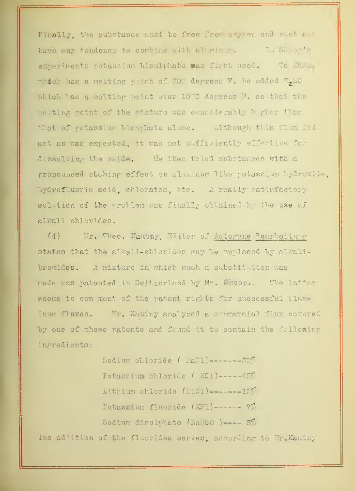
iTEITE-^OUTHT^ EIE01AICE TESTING MACHIKE
The load is applied at D where it hangs upon a collar in
which the sleeve mounted upon the test piece turns upon roller
hearings. The nucher of turns Lc indicated "by the counter at C
driven hy a worm and worm wheel which receives its motion from
the test piece B hy means of a flexihle connecting link F. The
test piece C is fastened in a traw-in collet driven into the
pulley A. A is turned "by a "belt from a motor at a constant speed
of 1.700 R.P.M.

moment arm in inches and i/c is the soctiori modulus, rave
the neries of values for the stress recorded in the Log.
Sheet, Table 1. The moment arm used was the distance from
the action line of the lo* d to the section at which failure
occurred. The relation "between the number of repetitions
of stress and the magnitude of stress seems to he expressed
by or. exponential lav/, . if the logarithms of these two
variables are plotted as coordinates the curve is a straight
line whose slope is the exponent. As this gives » means of
comparison with similar curves for other materials the loga-
rithms of rtress and repetition of stress were plotted rather
than the direct magnitudes.
Ordinary aluminum castings are quite solid, while
some of the castings used in the tests were weakened by blow-
holes so that all those that showed a flaw such as a cavity
or foreign matter in the section at which failure occurred
were eliminated in deciding imon the position of the curve
through the points. Of the eighteen endurance tests made,
eleven showed solid sections at the break. These eleven
points are plotted on the accompanying curve sheot. A straight
line seems to govern the relation between the logarithms of
the magnitudes of the stress and repetition of stress.
Taking the simple straight line formula
x = k - my
and letting x = log of repetition of stress y= magnitude of
stress, we have,
( R « number of repetitionslog R = k - m log S \
A A » _ »- ( S = magnitude of stress.See references # 4 tn3 #3
v r

For the lino thru the ^oints plotted n = 8.83 and k«41.3.
The equation poverninp the relation "between the stress and
repetition of stress then is
lop R = 41.3 - 8.83 lop 8 fl)
This may also he put in the form
log 3 =4.68 - .113 lop E
or S =43000 K
It is interesting to note that equation fl) is almost iden-
tical with the relation developed hy Upton end Lewi! "or
steel which has -.118 as an exponent. The enuation de-
veloped for steel is
lop R- 43.78 - 8.5 lop S
or S = 140000 R" a18
The average value of the exponent for tests in different
steels as recorded by Basmiin* is also ahout~.ll.
(16) STRENGTH OF WELDS SUBJECT TO FATIGUE TESTS.
Of the twenty welds made "by R. B. Rodpers two "broke
under the pressure of the cut 1 inp tool while the specimens
were heinp turned down to dimensions in the lathe. Three
were kept for tensile tests.
Of the fifteen Pieces subjected to endurance tests
nine "broke out of the weld rnd six "broke in the weld. Of
the nine pieces that "broke out of the weld four breaks may
he attributed to poor castings such as blowholes end forei pn
matter. This leaves five pieces breaking out of the weld
against six that broke In the weld showinp that as far as the
mere breakinp is concerned the welds stand up "uite favorably
* Reference #0 in Bibliography. I Q ee feferonce # 4


apainst the original met; 1. However, when the logarithms of
stress end numbers of repetitions are plotted on the sheet
showinp the relation between these variables for the unwelded
metal it will he seen that in strength the "balance lies de-
cidedly in favor of the unwelded test pieces. Only one
loint lies above the line established "by the oripinal alum-
inum, and one point falls upon the line. All others lie
"below the line and considerably "below points for the oripinal
metal that do not lie on the line. Of the breaks that oc-
curred in the weld only one showed a perfect weld, the re-
maininp five showed either a knotty unfused structure as if
the oxide film previously spoken of had prevented a flowinp
topether of the metal, or the section at the break was tra-
versed by one or more hark-like crystals also due to imper-
fect welding.
In the duality of the welds those made "by the Davis-
Bournonville Company were somewhat superior to the Rodpers
'
welds. Only one of the six pieces broke at the weld due to
an imperfection of the weld. One break that occurred out of
the weld may be attributed to a poor castinp. Countlnp the
two breaks that occurred while the test pieces were beinp
machined eipht of Rodpers 1 welds broke in the weld apainst
nine out of the weld, of which four ma£ be ; ttributed to poor
castinp. Of the iJavis-Bourr.onvllle welds three broke in
the weld and three out, of which one may be {ttributed to poor
casting. The ratio of breaks in to breaks out of the weld
is t>en for P.odpers 8/5, for levis-P.ournonville 3/g. However,


it can "be said that only one of the latters 'were unhomoponcou
or contained foreign particles, while of the Rodpor.s nreldfl
f including the two that "broke in the lathe) seven showed
such defects and only one web perfect. In strenpth, when
subject to repeated stresses, the Lavis-Bournonville welds nre
also "below the oripinal metal.
(17 ) EFFICIENCY OF WE^DS III TENSION.
The same remark concerninp the duality of the welds
applies to the test pieces subject to tension. Only three
Kodp-ers welds were put to tension tests all of which "broke
in the weld. Two showed rather a low tensile strenpth. The
"breaks indicated poor fusion of the metal "by the knotty
appearance. The third rave a tensile strength higher than
that of the average unwelded rod showinp that it is possible
to attain pood results.
By effi c iency as here used is meant the ratio of
unit stress at which rupture occurred for the welded rod to
the cvcrape unit tensile tensile stress for the unwo : ded
metal. The efficiency of the three Rodrers welds averaped
54.4$, and the averape efficiency of the Eavis-Bourninville
welds 7/as 73.4$, rsnpinp for the former from 27 to 101$, for
the latter from 50 to 86$. The welds here show the same
tandency as in the endurance tests, those made "by the Davis-
Bournonville Company heinp more nearly of the same duality,
while Rodpers 'welds show "both hipher f nd lower strenpths.
Host of the former "broke out of the weld "but ouite close to
it indicatinp that oripinal metal had "been weakened at the

weld. Small "blowholes , of which there wai a consider; hie
number, did not seem to weaken the tost niocor materially
in tension. The efficiency of the two Davis-Bourncnville
test pieces that "broke in the weld was 80%.
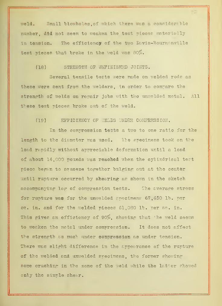
(18) STRENGTH OF UNFINISHED JOIIITS.
Several tensile tests were made on welded rods as
these were sent from the welders, in order to compare the
strength of welds on repair jobs with the unwelded metal. All
these test pieces "broke out of the weld.
(19) EFFICIENCY OF .VELDS UNDER COMPRESSION.
In the compression tests a two to one ratio for the
length to the diameter was used. The specimens took on the
load rapidly without appreciable deformation until a load
of about 14,000 pounds was reached when the cylindrical test
piece began to squeeze together bulging out at the center
until rupture occurred by shearing as shown in the sketch
accompanying log of compression tests. The average stress
for rupture was for the unwelded specimens 67,450 lb. per
sq . in. and for the welded pieces 61,080 lb. per sa. in.
This gives an efficiency of 90$, showing that 4 he weld seems
to weaken the metal under compression. It does not affect
the strength as much under compression as under tension.
There was slight difference in the appei ranee of the rupture
of the welded and unwelded specimens, the former showing
some crushing in the zone of the weld while the latter showed
only the simple shear.


While the compression -pieces gave consider; "hie
reduction in length or deformation "before rupture, the rods
subject to tension showed no elonpation measurable hy means
of direct measurement with o sccle.
(20) STATIC LOAD TBS5C ON OR 10 [HAL ALUMINUM.
An interesting chi racteristic of aluminum is shown
in the curve in which deflection is plotted apoinst load.
These tests were conducted in the White-Souther machine in
which the test piece was fixed and held stationary while an
increasinp load was applied at the end rnd the deflection
noted on a deflectometer connected to the specimen hy meons
of a fine wire. Up to a thirty pound losd the deflection
varied directly as the load, while for loads greater th; n that
the deflection increased faster than the load indicatinp that
the metal has a vtryinp modulus of elasticity. The stress
in the outermost fihre et the section of maximum stress pot
hy the eouation * vie/ 1 was for the 50 lh. load ahout
10,000 lh.per so. in. Durinp the compression tests it was
noticed that the test piece "began to crush et ahout 14,000 Id.
per 3d | in. The yield -point for aluminum under compression
lies apparently around 10,000 lh. per so. in., the two phe-
nomena, that of crushinp or spreadinp of the metal under com-
pression and the increasinp deflection of the cantilever "beam
"being occasioned hy the same characteristic of the metal.
As all of the tests for endurance '-'ere conducted for
loads of 30 lh. or preater it will he seen that the metal
was put to a stress apparently rreater than the elastic limit.

_ ~»"> r
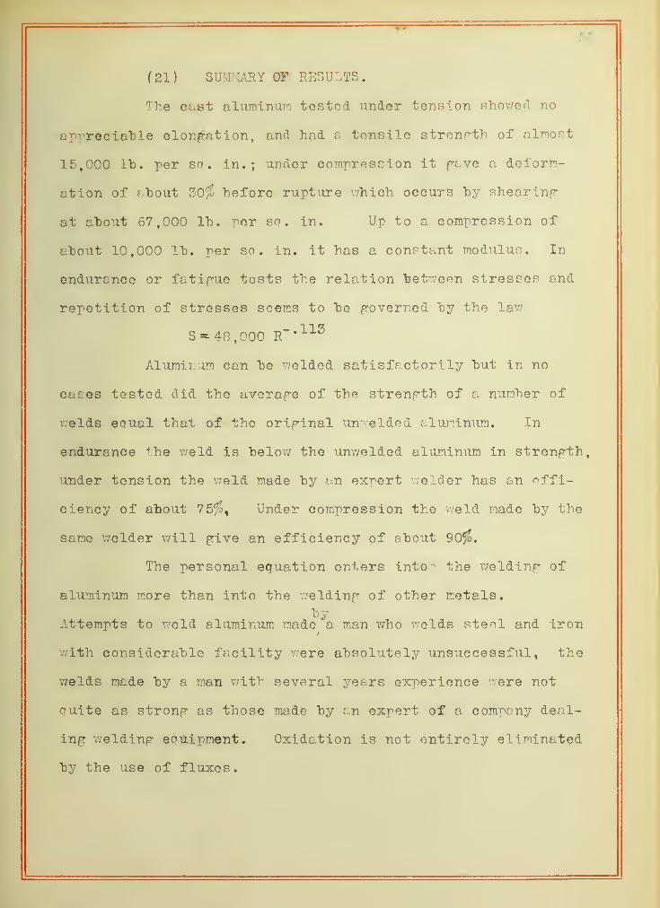
(21) SUMMARY OF RESULTS.
The cast aluminum tested under tension showed no
op-^reciahle elongation, and had 8 tensile strength of almort
15,000 Id. per so. in.; under compression it geve a deform-
ation of ? "bout 30% hefore rupture which occurs "by shearing
at ahout 67,000 lh. per sq. in. Up to a compression of
aho\it 10,000 lh. per so. in. it has a constant modulus. In
endurance or fatigue tests the relation "between stresses and
repetition of stresses seems to he governed hy the lav/
S = 48,000 R~*112
Aluminum can he welded satisfactorily hut in no
cases tested did the average of the strength of a numher of
welds equal that of the original unwelded aluminum. In
endurance the weld is helow the unwelded aluminum in strength,
under tension the weld made hy an expert welder has an effi-
ciency of ahout 75/£, Under compression the weld made hy the
same welder will give an efficiency of shout 90$.
The personal equation enters into j the welding of
aluminum more than into the welding of other metals.
oyAttempts to weld aluminum made a man who welds steel and iron
*
with considerahle facility were ahsolutely unsuccessful, the
welds made hy a roan with several years experience were not
quite as strong as those made hy an expert of a company deal-
ing welding equipment. Oxidation is not entirely eliminated
hy the use of fluxes.


TABLE I
LOG OF ENDURANCE TESTS.on
UMWELDED .ALUMINUM* -1J \J AM, X J 1 U X\l *
i/cnu • xi ldin •T. r\ n ilX 111 M "Raw Tin it U \j X v u C Lo tr
1 11 • x D . ill. 7*AVX C V • • J h 1 kJ O
Ri n 4^ 4 4. 1 QRX .7 o m 4o. U X 1 \J 1 41 40 4 1 51
Atht 4 A 4 7A 1 Q AX ;7 O 4- 4R7 oi pq|Ulb? 4 1 ft?
DO Al F Af> 4 1 K*t . XtJ PD7 4 R49 01 "34. U X Crt- 1 F440 4 IRQ
X> .7HI P An 4 nn cuu 4 A7R m 34. U X C*x ItJvU 4 174
To A 4n 4 X f fj 7*3800 4 OAR*r . O DO m pa. w X U 4 1 3Ax| lUUU W An? 4 PR X ( \J 4P Af)0 4 APRX # U M *W 01 24#Ulw x 1 3700 4-137
• \jyjo ^A 4 ?n 147 '3;7 PQOO iJ • LM J. m pq 1 1 400 4 057X* VV All 4 4 A irrX U «J p rq Rnn 5 41 4«V # X^E 01 ^1 1 1R40X XUx^ 4-074
ADR 4 ?n "1 PAX C D roi 400 K Q04 01 PQ Q7R0 3 QQOAOR 30 ? 1 A 64 424700 5 A?
7
01 PQ F)000
Fe 514• X" 50 4-20 210 16600 4-220 .0133W Ul. t^1 o 15800 4.199Pw .511 50 4.25 £ 12 4700 3.672 .0131 16200 4.210Ge .505 45 5.35 151 1400 3.146 .0126 12000 4.079Gv: .524 45 4.30 193 41500 4.616 .0141 13700 4.136He .504 40 4.15 166 22200 4.346 .0126 13200 4.120Hw .504 40 4.35 174 65700 4.817 .0126 13800 4.141Ie .506 45 3.65 164 33700 4.527 .0127 12900 4.111Iw .502 45 4.20 189 33700 4.527 .0124 15200 4.183
DESCRIPTION OF TEST PIECESfor
ENDURANCE TESTS,f B^; section is meant the "break )
Ae - Very poor section. Larpe "blow hole.Aw - Section 0. Z.3e - Section 0. K.Bw - Section 0. K.Ce - Section 0. K.Cw - Section partly darkened as if "by foreign matter- in metal.De - Section 0. K.Dw - Section C. K.Ee - Section 0. X. except for small hlov; hole on circumference.Ew - Broke away from section of maximum stress 2" from end.Fe - Section 0. K.Fw - Section 0. K.Ge - Broke away from section of maximum stress at large "blow hole.Gw - Section 0. K.He - Two small flaws in section.Hw - Section 0. K.Ie - Section 0. X. except for one small "blow hole.Iw - Section 0. K.


TABLE II
LOG OF ENDURANCE TESTSon
WELDED ALUMINUM.
*
x< ij •T)-i nrin
* J \JG« XXX III M x * V . J.OCT i/cx/ ' > 1/ x o o o TiCi rr±* \j fj,
1 "hJ. u . i n X V V .
iie ^A 4 PH X*i 1 ^ 71 A m pr 1 1 74Dill tu 4 O AOA TT7 ahp ^A 4 1 A 1 4 AX*± »-> A4nn A 4ft4-ij . 1 O *x m P4. 1 1 7nn 4 H A7ft « \J O f
ue ai i 4nftU 4 in 1 A4 77 QHO 4 AQPft » O i7 << m ^i. U XtJ X i paoo 4 HQ A
X'
W
ADA 4nftU t3 . £>U 1 4f> 1 1 7DO 4 n ap m P7 1 1 DADX. XUftU 4 D47u e • DUxJ 4R 4 r=;n ouu P 477 1 A7 4H10/ ftU 4 1 OAft . JL f DCw AD7 4 A A 4.0 X.JO PDD p m pn 1 ^ARCiXJtOU *x . X O J
De .506 45 3.70 167 101900 5.007 .0127 13140 4.118Dw .505 45 4.30 194 57700 4.761 .0126 15400 4.187Se .509 30 4.20 126 .0129 9750 3.989Ew .508 30 4.20 126 300 2.477 .0128 9640 3.993Fe .512 50 5.75 188 100 2.000 .0132 14240 4.153Fw .505 50 3.90 195 .0128 15220 4.182Ge .505 59 4.50 135 70800 4ls49 .0125 10800 4.033Gw .504 30 4.45 133 85600 4.932 .0126 10550 4.023He .512 30 4.50 155 100 2.000 .0132 10220 4.009
DESCRIPTION OF TEST PIECESfor
ENDURANCE TESTS,f By section is meant the "break )
Ac - Broke in weld. Bark-like flaws on edge of section.Aw - Broke in weld. Section 0. X. Slight flaw in edge.Be - Broke in weld. Section 0. K. Slight flaw in edge.Bw - Broke out of weld. Section porous with minute "blow holes.Ce - Broke out of v/eld. (stock sido) Section crystalline 5b rough.Cw - Broke out of weld (stock- side) Small particles foreign matter.De - Broke out os weld (stock side) Section 0. X.Lw - Broke in v/eld. Section 0. K.Ee - Broke in weld. Poor fusion. Bark-like section.Ew - Broke in weld. Poor weld. Bad flaw. Bark-like section.Fe - Broke out of weld, (end side) Flaw. Foreign matter in sectionFw - Broke out of weld, (end side) Flaw. Quite porous.Ge - Broke out of weld, fstock side) Section 0. X. central flaw.Gw - Broke out of weld, (stock side) Section 0. X.Ee - Broke out of weld, (stock side) Poor section.
* Welds made "by R. B. Rodgers


TABLE III
LOG OF ENDURANCE TESTSon
WELLED ALUjvIIjJIM.*
Ho, Diam. Load Arm M Rev. Log i/c Stress ~ogin. rb. in. rev. Stress
A .504 45 5.45 155 P3500 4 ^7T 01 PA
B .498 50 2.80 140 400 2.602 .0121 11560 4.063
C .502 40 154 135600 5.126 .0124 10800 4.034
D .500 55 2.70 94 249500 5.597 .0123 7670 3.885
E .502 30 5.25 97 84800 4.928 .0124 7860 3.896
F .500 50 5.40 170 100 2.000 .0123 15800 4.141
DESCRIPTION OF TEST PIECES.
A - Broke in weld, one diametral "bark-like flaw.
B - Broke out of weld. Section good. Loose crystals.
C - Broke in weld. Homogeneous section.
D - Broke out of weld. Good section.
E - Broke out of weld. Three small blow holes on circumference.
F - Broke in weld. Solid section with diametral flaw.
* Davis-^ournonvil 1 e wolds.

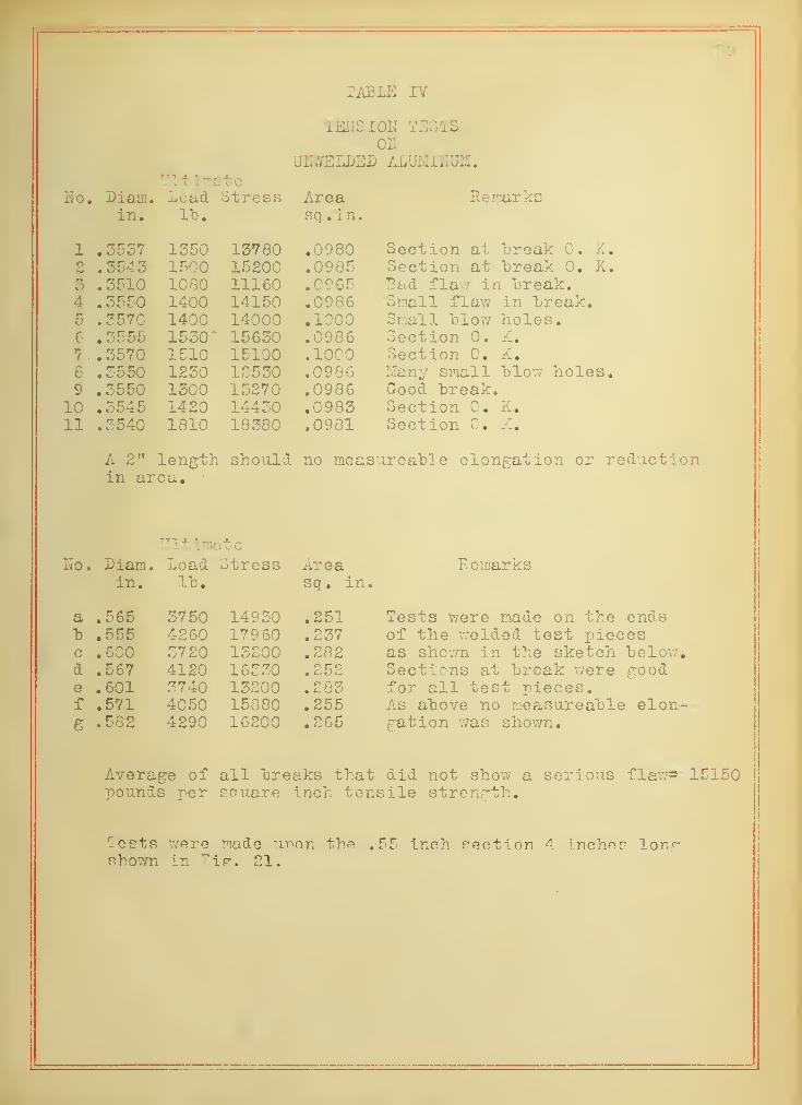
TABLE IY
TENSION TESTSOil
UNiVELDEI) ALUMINUM.Ultimate
Ho. Diam. Load Stress Area Hemarksin. rb. sq . in.
1 .3537 1350 13780 .0980 Section at creak 0. K.pB .3545 1500 15200 .0985 Section at "break 0. K.3 . 3510 1080 11160 .0965 "Bad flaw in "break.4 .3550 1400 14150 .0986 Small flaw in "break.r»
D .3570 1400 14000 .1000 Small "blow holes.6 .3555 1530" 15630 .0986 Section 0. K.7 . .3570 1510 15100 .1000 Section 0. X.e .3550 1230 12530 .0986 Many small "blow holes.9 .3550 1300 13270 .0986 Good "break.
10 .3545 1420 14430 .0983 Section 0. K.11 .3540 1810 18380 .0981 Section 0. K.
A 2" length should no measureahle elongation or reductionin area.
UltimateHo. Diam. Load Stress Area Remarks
in. Id. sq. in.
a .565 3750 14930 .251 Tests were made on the ends"b .555 4260 179 60 .237 of the welded test piecesc .600 3720 13200 .282 as shown in the sketch "below.d .567 4120 16330 • Cj f} *3 Sections at "break were goode .601 3740 13200 .283 for all test pieces.f .571 4050 15880 .255 As ahove no measureahle elon-e .582 4290 16200 .265 gation was shown.
Average of all "breaks that did not show a serious flaw*- 15150pounds per square inch tensile strength.
Tests were made imon the .55 inch section 4 Incho? longshown in Fijr; 21.

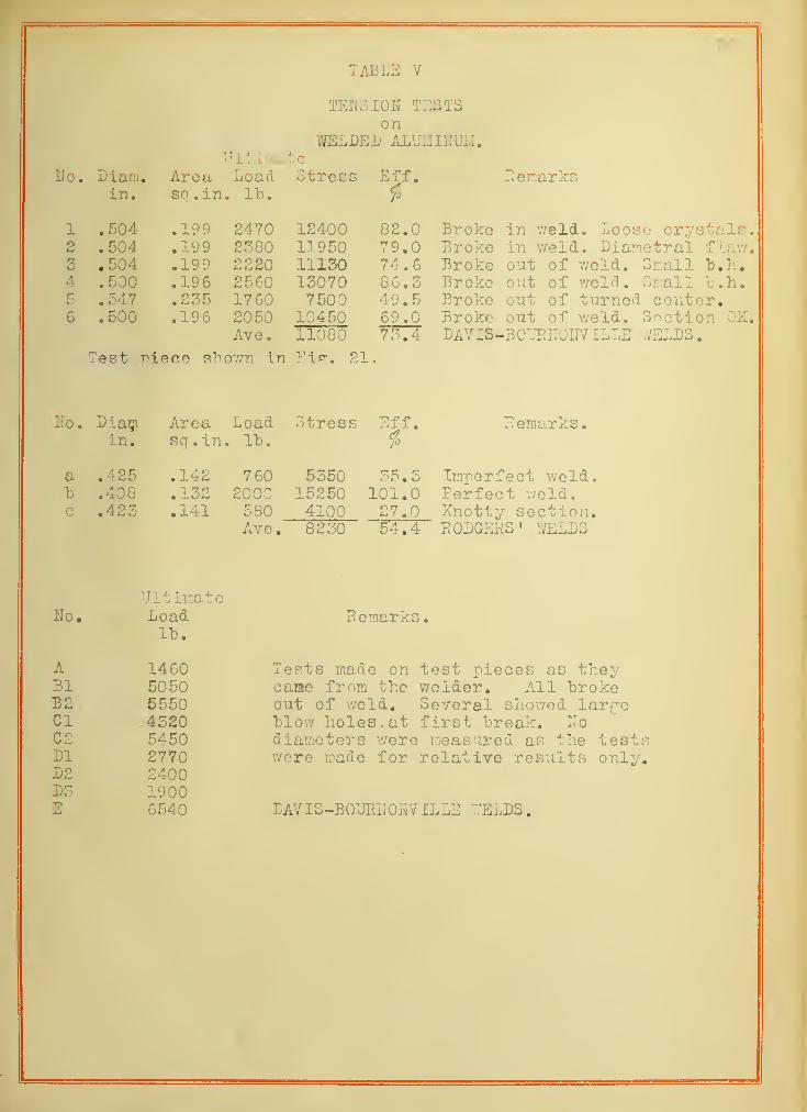
TABLE V
Ho. Diam,in.
TENS IOH TESTSon
WELDED ALUMI1IUM.Ultimate
Area Load Stressso. in. l"b.
Eff.i
Remarks
1 .504 .199 2470 12400 82.0 Broke in weld. Loose crystals.2
34
.504
.504
.500
.547
.500
.199
.199
.196
.235
.196
23802220256017602050Ave.
11950111301307075000450
11080
79.0 Broke in weld. Diametral flaw.74.686.349.569.073.4
Broke out of weld. Small "b.h.
Broke out of weld. Small "b.h.
Broke out of turned center.Broke out of weld. Section OK.DAVIS-BCURITOUV ILLE -/ELDS
.
Test r^iece shown in Fi.fr. 21
Ho. Diam Area Load Stress Eff. Remarks,in. sq.in. It. fo
a .425 .142 760 5350 35.5 Imnerfect weld,"b .408 .132 2000 15250 101.0 Perfect weld,c .423 .141 580 4100 27.0 Knotty section.
Ave. 8230 54.4 RODGERS ' WELDS
UltimateHo. Load Remarks.
It).
A 1460 Tests made on test pieces as theyBl 5050 cane from the welder. All "brokeB2 5550 out of weld. Several showed largeCI 4320 "blow holes, at first "break. HoC2 5450 diameters were measured as the testsDl 2770 were made for relative results only.D2 2400D3 1900E 6540 BAVIS-BOURHOFvILLE "'ELDS
.


TABLE VI
COMPRESSION TESTSof
UU.YELDED ALITJIlItJM.Ult inrate
T\Tr»rJO. Liam H v*o q a Lengthin. sq . in. lb. int. final <*
/J
1 .750 .442 31000 70500 1.52 0.93 29.52 .750 .442 27800 63200 1.52 1.01 23.55 .756 .448 30700 68700 1.52 0.95 28.04 .751 .443 28880 65500 1.51 0.94 28.65 .756 .448 31300 70100 1.42 0.96 32.46 .753 .445 28100 65400 1.45 1.02 28.67 .750 .442 31500 71600 1.42 0.95 33.18 .750 .442 29200 66400 1.46 0.96 34.2
Ave. 67400 Ave
.
29.8
Specimens took load up to a"bout 14000 lb. after which thecylinders flattened out until failure at the loads indicated.Failed by shearing as shown "below.
Test niece taken out of3/4 inch stock of en-durance test nioeo shownin Fip. 19.
Ultimatelo. Liam. Area Load Stress Length Lef.
in. sq . in. lh. int • final $
a .652 . 333 23870 71800 1.21 0.80 33.8b .601 .283 15440 54600 1.21 0.86 28.9c .646 .327 25000 7 6600 1.20 0.78 35.0
Ave. 67600 Ave
.
32.6
Stock left over from tension tests of which the results ar
tabulated in Table V. Section U was used for tests a, b, and
! ection Sf was used for compression tests on welded aluminum.

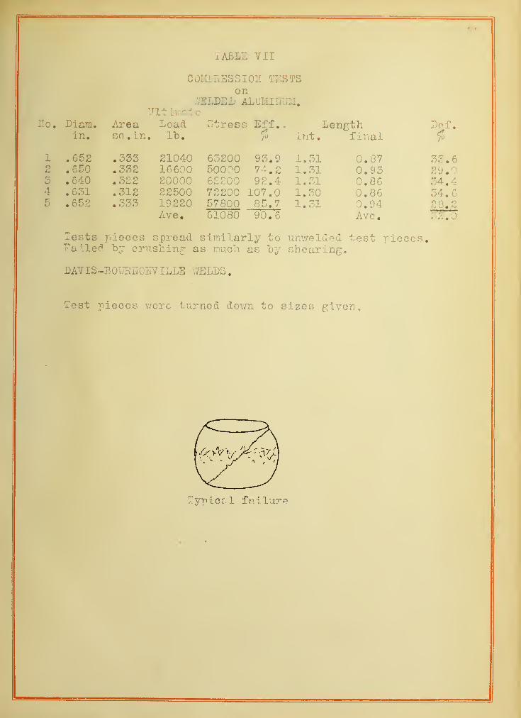
x ABLE VII
COMPRBSSIOH TESTSon
.VELBEJD ALUMINUM.TJlt inate
Ho. Diam. Area Load Stress Eff . . Length Lcf.in. sq.in. lh. ft int. final $
1 .652 .333 21040 63200 93.9 , 1.31 0.87 33.62 .650 .332 16600 50000 74.2 1.31 0.93 29.03 .640 . ii>2 2 20000 62200 92.4 1.31 0.86 34.44 .631 .312 22500 72200 107.0 1.30 0.86 34.65 .652 . 333 19220 57800 85.7 1.31 0.94 28.2
Ave. 61080 90.6 Ave.: 2.0
Tests pieces spread similarly to unv/elded test pieces.Failed "by crushing: as much as "by shearing.
LAVIS-BOURUOFVILLE WELDS.
Test pieces were turned down to sizes given.
Typica 1 fa i lure


TABLE VIII
STATIC LOAD TESTon
UN (7ELDBD AftJMXHlffl.
7f2 #3
P Deflec
.
P Dexlec
.
load in load inin l"b. inches
.
in lt>. inches.
• 0000 .00005 .0036 5 .0049
10 .0068 10 .009215 .0108 15 .015020 .0143 20 .019525 .0167 25 .024850 .0216 30 .029735 .0264 3540 .0311 40 .040845 .0367 45
A r* A D• 0o02
50 .0436 50A/* AO
55 .0510 55 /"V Tf /"V O.070260 .0611 60 .084565 .0710 65 .099070 .0840 70 .120075 .0982 75 . 134080 .1100 80 .169085 .1319 85 ."break90 ."break
"enpth 5.9 inches .enrth 4.15 inches
P


LOG. STRESS - LOG. REVERSALS CURVEfor
Endurance Tests of Unwelded ffluminu mand POINTS
forEndurance Tests of VVelded flluminurn
q unvu elded aluminum
O welded aluminum ( Rodgers)
© welded aluminum (Davis - Bout?)
.98 3Q 40 42 44 46 4,


BIBLIOGRAPHY.
1. Autogene Schweissuag von Aluminium,
"by Theo, Kautny.
Auto gene Met"Ilbec rheitung- February 19 13.
2. Autogenous TJelding of Aluminum, .
"by M. U. Shoop
Electro-Chemical and Met.Ind.- April 1909 and May 1909.
3. Repair of Aluminum Castings "by Oxy-acetylene Blow-pipe,
Autojnojbile- April 22, 1909.
4. Fatigue Failure of Metals,
"by Upton and Lewis.
American Machinist- October IV, 1912.
5. A Theory of the Welding of Steel.
Scientific American Supplement- June 22, 1912.
6. Aluminum Casting Repairs,
Iron Age April 22, 1912.
7. Experiments on the Strength and Fatigue Properties of Jelded
Joints in Iron and Steel,
by T. E. Stanton end J. R. Pannell.
Proceedings of the Institute of Civil Engineers
.
Dec. 12, 1911.
8. The Experimental Law of Endurance Tests.
by Basquin
Proceedings of the American Society for Testing Materials 1910