01 the fatigue and static properties of butt welds in structural - Ideals
113
........ tf:8f CIVIL ENGINEERING STUDIES STRUCTURAL RESEARCH SERIES NO. 81 01 THE FATIGUE AND STATIC PROPERTIES OF BUTT WELDS IN STRUCTURAL STEELS By L. A. HARRIS and G. E. NORDMARK Approved by N. M. NEWMARK and W. H. MUNSE UNIVERSITY OF ILLINOIS URBANA, ILLINOIS
Transcript of 01 the fatigue and static properties of butt welds in structural - Ideals

........
~;2qA-
tf:8f CIVIL ENGINEERING STUDIES
STRUCTURAL RESEARCH SERIES NO. 81
~3 01
THE FATIGUE AND STATIC PROPERTIES OF BUTT WELDS
IN STRUCTURAL STEELS
By L. A. HARRIS
and
G. E. NORDMARK
Approved by
N. M. NEWMARK
and
W. H. MUNSE
UNIVERSITY OF ILLINOIS
URBANA, ILLINOIS
THE FATIGUE AND STATIC PROPERTIES OF BUTT WELDS
IN STRUCTURAL STEELS
L. A. Harris
and
G. E. Nordmark
Approved by
N. M. Newmark
and
W.R. Munse
A Report of an Investigation 'Conducted by
THE DEPARTMENT OF CIVIL ENGDJEERING
UNIVERSITY OF ILLINOIS
In Cooperation With
THE OHIO RIVER DIVISION LABORATORIES
CORPS OF ENGINEERS
U. S • .ARMY
Contract No. DA-33-017-eng-221
UNIVERSITY OF TILINOIS
URBANA, ILLINO IS
JUNE 30, 1954
I.
CONTENTS
Introduction. . . • • • .
1.
2.
Object and Scope of Investigation ••
Acknowledgement . • . . . ~
Page No.
1
1
3
II~ Description of Test Procedures. • 5-
3· Description of Steel. • • • • • • • 5
4. Preparation o.f Longitudinal Butt Welds. · 5
5. Preparation of Transverse Butt Welds. 8
6. Test Procedures . • . • • • • • • • • 10
III. Tests of' Longitudinal Butt Welds in ASTM A 7 Steels. 13
7 .. Results of' Present Fa.tigue Tests of
Longitudinal Butt Welds .
8. Results of Present Static Tests of'
Longitudinal Butt Welds ~
9. Review of Previous Longitudinal Butt Weld
13
17
Fatigue Tests. • . • • • .• 18
rv. Tests of Transverse Butt Welds in ASTM A7 Steels.. 21
10. Results of Present Fatigue Tests on
Transverse Butt Welds. . .
11. Results of' Present Static Tests of'
Transverse Butt Welds
12. Scope of the Study of' Previous Fatigue Tests
2l
24
of Transverse Butt Welds. . . . • • • • • •• 24
CONTENTS (CON'T)
Page No.
13. Review of Past and Present Fatigue Tests
of Transverse Butt Welds with the Reinforcement
On: O-Tens ion Cycle. . • • • • • • • • • • 26
14. Review of Past Fatigue Tests of Transverse
Butt Welds With the Reinforcement On:
Tension = Compression Cycle • . •
15. Review of Past and Present Fatigue Tests of
Transverse Butt Welds with the Reinforcement
Removed. •
V. Review of Past Fatigue Tests of Transverse Butt
Welds in Silicon Steel and in Low Alloy High Tensile
steel. . . . . . . . . 16. Scope of Investigation.
17· Review of Past Fatigue Tests of Transverse
Butt Welds in Silicon Steel . . . . . . . . 18. Review of Past Fatigue Tests of Transverse
32
. 37
37
38
Butt Welds in Low Alloy High Tensile Steel. 39
VI. Summary and Conclusions •
20. Conclusions .•
Bibliography . • • •
41
41
43
4B

TABLES
1. Chemical Composition of Steel Plate
2. Physical Properties of Steel Plate
3. H'elding Procedures
4. Results of Longitudinal Butt Weld Fatigue Tests
50 Results of Plain Plate Fatigue Tests
6. Location of Initiation of Fatigue Fractures in
Longitudinal Butt Weld Specimens
7- Results of Static Tests of Longitudinal Butt Welds
8. Results of Past and Present Fatigue Tests of
Longitudinal Butt Welds
9. Properties of Plate Material Used in Past and Present
Longitudinal Butt Weld Fatigue Tests
10 . Results of Transverse Butt Weld Fatigue Tests
11. Results of Static Tests of Transverse Butt Welds
12. Properties of Plate Material Used in Past and Present
Transverse Butt Weld Fatigue Tests
13. Results of Past and Present Fatigue Tests of Transverse
Butt Welds in the As-Welded Condition: O-Tension Cycle
14. Average Results of Past and Present Fatigue Tests of
Transverse Treatments: O-Tension Cycle
15. Results of Past and Present Fatigue Tests of Transverse
Butt Welds with the Reinforcement On Prepared with Special
Treatments: O-Tension Cycle
TABLES (CON' T)
16. Results of Past and Present Fatigue Tests of Transverse
Butt Welds with the Reinforcement On:
Tension = Compression Cycle
17. Results of Past and Present Fatigue Tests of Transverse
Butt ltlelds with the Reinforcement Removed
18. Properties of Silicon Steel and Low Alloy High Tensile
Steels Used in Past Fatigue Tests of Transverse Butt Welds
19- Results of Past Fatigue Tests of Transverse Butt Welds in
Silicon Steel and in Low Alloy High Tensile Steels

FIGURES
1. Location of-Specimens in Parent Plate) Plate 10
2. Location of Specimens in Parent Plate) Plate 9
3. Location of' Specimens in Parent Plate) Plate 8
4. Location of Specimens in Parent Plate, Plate 7
5· Location of Specimens in Parent Plate) Plate 6
6. Details of Butt Weld Specimens
7· Welding Jig for Longitudinal Butt Weld Specimens
8. Details of Welding Sequence for Longitudinal Butt Welds
9. Details of Preparation of Transverse Butt Weld Specimens
10. Schematic Diagram of Wilson Fatigue Testing Machine
li. Results of Fatigue Tests of Longitudinal Butt Welds
12. Typical Fracture Surfaces of Plain Plate Fatigue Specimens
13· Typical Fatigue Fractures of Longitudinal Butt Welds with the
Reinforcement On.
14. Typical Fatigue Fractures of Longitudinal Butt Welds with the
Reinforcement Removed by Grinding
15. Results of Past and Present Fatigue Tests of Longitudinal Butt Welds
16. Results of Fatigue Tests of Transverse Butt Welds
17. Typical Fatigue Fractures of Transverse Butt Welds with the Reinforcement
On
18. Typical Fatigue Fractures of Transverse Butt Welds with the Reinforcement
Ground Off
190 Typical Macrographs of Plane Normal to Fatigue Fractures
20. Results of Past and Present Fatigue Tests of Steel Plate Used in
Transverse Butt Weld Investigations

FIGURES (CONTT)
21. Results of Past and Present Fatigue Tests of Transverse Butt
Welds in the As-Welded Condition Prepared with E6ol0 and E6ol2
~ectrodes: O-Tension Cycle
22. Results of Past Fatigue Tests of Transverse Butt Welds in the
As-Welded Condition Prepared with E6ol3 and E6030 Electrodes:
O-Tension Cycle
23· Results of Past Fatigue Tests of Transverse Butt Welds in the
As-Welded Condition Prepared by Automatic Procedures:
O-Tension Cycle
24. Summary of Results of All Past and Present Fatigue Tests of
Transverse Butt Welds in the As-Welded Condition: O-Tension Cycle
25. Results of Past Fatigue Tests of Transverse Butt Welds with the
Reinforcement On Welded with Special Procedures: O-Tension Cycle
26. Results of' Past and Present Fatigue Tests of Transverse Butt Welds
in The As-Welded Condition Prepared 1.;ith E6ol0, E6ol2, and E6ol3
Electrodes: Tension = Compression Cycle
27· Results of Past and Present Fatigue Tests of Transverse Butt Welds
in the As-Welded Condition Prepared with E6020 and E6030 Electrodes
and with Automatic Procedures: Tension = Compression Cycle
,28. Summary of Results of All Past and Present Fatigue Tests of Transverse
Butt Welds in the As-Welded Condition: Tension = Compression Cycle
29 . Results of Past Fatigue Tests of Transverse Butt Welds with the
Reinforcement On Welded with Special Procedures: Tension = Compression
Cycle

FIGURES (CON'T)
30. Results o~ Past and Present Fatigue Tests of Transverse Butt
Welds with the Reinforcement Off: O-Tension Cycle
31. Results of Past and Present Fatigue Tests of Transverse Butt
Welds with the Reinforcement Orf: Tension = Compression Cycle
32. Results of Past Tests of Transverse Butt Welds in Silicon Steel
and in Low Alloy High Tensile Steel

THE FATIGUE AND STATIC PROPERTIES OF BUTT WELDS
IN STRUCTURAL STEELS
I. INTRODUCTION
1. Object and Scope of' Investigation
1.
It has been the purpose of most of' the previous fatigue tests
of' welded joints to provide sufficient experimental data from which
it would be possible to determine, quantitatively, the fatigue strength
-of' welded joints of different types, and thence, to determine allowable
stresses for use in the design of structures subjected to repeated
loads.. These data were accumulated both L."'1 the United Stat.es and abroad.
In the United States, the test programs were conducted under the guidance
of the Fatigue Committee of the Welding Research Council, most of the
experimental programS being conducted at the University of illinois
in f'atigue machines designed specifically for the purpose by Prof'essor
w. M .. Wilson.
With advances in welding techniques, recent interest has
been directed towards methods of improving the fatigue behaviour of
1ve1dments. During the last three years, the Ohio River Division
Laboratories of' the Corps of Engineers, U. S . .Army has sponsored a
research program at the University of Illinois which has had as its
chief objective a comparison of the properties of' welds produced
with the low hydrogen ~ype electrode or with the cellulose type
electrode, which has a high hydrogen content. The earlier work on

2.
this program was concerned with a comparison of the properties of bead-
on-plate welds produced with these two types of electrodes and subjected
1* to various treatments 0 On the basis of these tests, and related tests
performed elsewhere, it was felt that the use of the low hydrogen
electrode might result in a weld more resistant to repeated loadings
than a weld produced with other electrodes. Therefore, a program
of small scale, polished, all-weld-metal specimens was designed to
study this possibilityo The results of the tests of the all-weld
metal specimens2 indicated that the weld metal deposited with the
E7016 electrode had a fatigue strength about 25,000 psi greater than
the fatigue strength of the weld metal deposited with the E6ol0 electrode
when the weld pads were preheated and air-cooledo The greater fatigue
strength of the weld metal deposited with the low hydrogen electrode
was reduced about 8,000 psi if the weld pad was water quenched two
minutes after each pass had been depositedo Small scale, polished
specimens containing weld metal and base plate fractured at about the
same fatigue strength as the base plate, regardless of the electrode
used to prepare the weldo
On the basis of the encouraging results from the all-weld-
metal fatigue tests of the low hydrogen weld metal, it was decided
to inaugurate a series of fatigue tests to determine whether this
improvement would be reflected in tests of full scale welded jointso
*Numbers in superscript refer to the references listed in the Bibliography at the end of the report.

3·
The present investigation represents the first phase of this study
of fUll scale welded. joints: a study of the fatigue and static
properties of butt welds 0
It is the purpose of the tests reported herein to compare
the fatigue and static properties of butt welds produced with the
E60l0 and the E70l6 electrodes. I
Two types of butt weld specimens
were tested: the longitudinal butt welds were tested with the applied
stress parallel to the direction of welding, whereas the transverse
butt welds were tested with the applied stress perpendicular to the
direction of welding.. The butt welds have been tested either with
the reinforcement on or with the reinforcement removed by grinding.
The specimens were subjected to a stress cycle which varied .from a
low tension of about 2000 psi to a maximum tension which was of such
magnitude that failure generally occurred between 100,000 and
In order to more thoroughly understand the behaviour of
butt welds subjected to repeated stresses, an extensive review o.f
the fatigue tests of butt welds conducted previously at the University
of Illinois bas been included in the reporto
20 Acknowledgement
This report is part of a cooperative research project
conducted in the Engineering Experiment Station of the University
of illinois, Department of Civil Engineering, and sponsored by

4.
the Ohio River Division Laboratories, of the Corps o~ Engineers,
u. S . .A:rmy, under Contract DA-33-0l7-eng-22l.
The work constitutes a part o~ the structural research
program o~ the De:partment o~ Civil Engineering under the general
direction of N. M. Ne-wmark, Research Pro~essor of structural
Engineering, and W. R. Munse, Research Associate Professor of Civil
Engineering. The research was performed by L. A. Harris, Research
Associate in Civil. Engineering, who was the immediate :project
supervisor; R. B. Matthiesen, Research Assistant in Civil Engineering,
and G. E. NordInark, Research Assistant in Civil Engineering.
The metallurgical stUdies were performed in the laboratories
of the Department of Mining and Metallurgical Engineering under the
supervision of R. W .. Eohl, Assistant Professor of Metallurgical
Engineering. (
The authors wish to acknowledge the assistance of the
members of the Fatigue Committ'ee of the Welding Research Council,
who acted in an advisory capacity.

5·
IIo DESCRIPrION OF TEST PRCCEDURES
3. Description of' Steel
In order to more closely control the chemical content,
and hence the weldability, of' the steel plate used in these tests,
the steel was ordered to comply with the American Bureau of' Shipping
specification f'or TYPe B steelo The chemical analysis and the
physical properties of the steel are given in Tables 1 and 2,
respectively. The steel meets both the ABS specification and the
ASTM A7 specification for chemical composition, but the average
physical properties do not meet either specification for tensile
strength, the average tensile strength being only 57,400 psi. One
spec~en had a tensile strength as low as' 55,600 psi.
The steel was supplied as 3/4 in. thick plates which were
6 ft. wide x 12 ft. long 0 The locations of the test specimens in
the parent plates are shown in Figs 0 1 through 5.
4. Preparation of Longitudinal Butt Welds
The details of the completed butt weld specimens are shown
in Fig 0 6. As indicated in this figure, the longitudinal butt weld
specimen was prepared from three pieces, the central section containing
the test weld and the two outside pull heads. This procedure was
followed in order to conserve material, the pull heads being prepared
from ~reviously tested specimenso

6.
The central section o~ the longitudinal specimen, 12 in.
wide x 22 in. long, was flame-cut from the base plate as indicated
in the plate lS\Vout diagrams. The 12 ino wide sections were saw cut
along their centerline to a 6 in. width and the saw cut edges were
machined in a shaper for a double V weld with a 60 degree included
angle and a 1/16 ino root opening.
In making the longitudinal weld, the two halves of the
plate were ~irst securely bolted to the welding jig shown in Figo 7.
This jig could be rotated about a horizontal axis to permit
deposition o~ all passes in the flat positiono Fig. 7 shows the
plates in position for welding a pass on each side of the specimeno
After deposition of the first pass, the weld was back chipped until
no visible defects were present 0 Approximately 15 minutes of air
cooling was allowed between the first and the second passes, but
only five minutes was allowed between succeeding passes. After
completion o~ the weld, the specimen was air cooled for 10 minutes
and was then removed "from the welding jig 0
The double V joint was deposited in s:ix passes, each
pass being deposited in the flat positiono In order to assure
that- a change in electrode would occur in the test section, the
welding sequence, shown in Fig. 8, was used. This welding sequence
was such that adjacent passes were welded in opposite directions
and changes of electrode in adjacent passes did not occur one over
the other.

Two types o~ electrode were used to prepare the welds, one
corres~onding to the AWS E6ol0 des~tion and the other to the
AWS ElOl6 designation. .All o~ the electrodes were 3/16 ino in
diameter and were operated at the values given in Table 3. These
values were measured on portable meters connected as close to the
arc as possible.
After completion o~ the longitudinal butt weld, the ends
of the test section were prepared for welding and the previously
drilled pull heads were welded to the test sectiono The specimen
was then machined to the dimensions given in Fig. 6 and the edges
were drawf'iled"
A portable disk gJ:inder was employed to remove the weld
reinfoTcement and the mill scale ~or those specimens to be tested
with the reinforcement removed. T"ne grinding was started with a
36 grit wheel and then finished with a 120 grit wheel in such a
manner that the scratches were parallel to the direction of loading 0
The mill scale was ground o~~ from one pull head to the other to
prevent failure at irregularities out of the test sectiono Grinding
was continued to a depth sufficient to remove the mill scale and
the rolling defects on the surface of the plateso The transverse
butt welds connecting the test section to the pull heads were
ground flush for all of the specimens in order to reduce the
occurrence of failure at these weldso

8.
After preparation of' the specimen in the above manner, the
width was measured with a 4-5 ino micrometer and the thickness with a
1 ino micrometer. The area was computed f'rom the average of' several
readings and the reported stress was computed f'rom this area. The
spec~ens which were tested with the weld 'reinforcement on were
measured at several points in the test section away from the weld
and the average area, not including the area of' the weld reinforcement,
was used to compute the stress. In the latter case, the measured
thickrless includes the thickness of the mill scale 0 After they were
measured, the specimens were ready for testingo
50 Preparation of Transverse Butt Welds
The plate material to be used for the transverse butt
welds was first flame-cut to the shape shown in Fig. 9ao This plate
was then saw cut at the joint and the joint was prepared in a shaper
.for a double V butt weld having an included angle of 60 deg 0 and a
1/16 ino root opening 0 The weld specimen had an increased width at
the joint to enable the machining of the start and the end of the
weld from the specilnens before testing 0 As stated above J 3/16 in.
diameter electrodes conforming to the American Welding Society
designations E6010 and ET016 were used to prepare the welds 0 The
welding procedure employed 6 passes and the electrodes were operated
at· the values, given in Table 3, which were measured on portable
meters connected as close to the arc as possibleo The welds were
thoroughly back chipped after deposition of the f'irst passo

9·
In welding the specimens, the two halves of the specimen
were first firmly secured in a welding jig similar to that used in
the welding of the longitudinal butt yeld spec:imens. The jig was
so arranged that the specimen and its table mount could be rotated
180 degrees. about a horizontal axis; therefore, all welding was
done in the flat position.
The 7 in .. width of the weld specimen was too wide to
allow the completion of a single pass without changing electrodes.
In order to more closely control the duplication of specimens, the
changes in electrodes were made at the points specified in Fig. 9b.
By use of' this procedure, every pass of tpe weld was stopped and
restarted within the test section and adjacent passes were welded
from opposite directions.. The welds were allowed to air cool for
five minutes between passes and were air cooled to room temperature
after completion of the jointQ
After welding was completed, the specimen was machined
to the final dimensions, given in Figo 6, and the edges were
drawfiledo' Those specimens to be tested with the reinforcement
removed were ground in the same manner as the longitudinal butt
weld specimens, except that the specimens were ground only for a
distance of about- 2 ino from each edge of the weldo The specimens
were measured and the stresses computed in the same manner as the
longitudinal butt welds.
10.
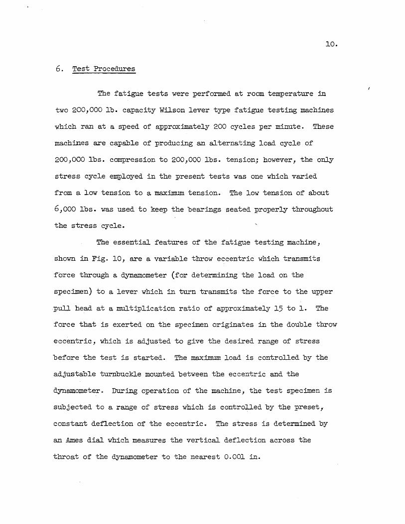
6. Test Procedures
The fatigue tests were performed at room temperature in
two 200,000 lb. capacity Wilson lever type fatigue testing machines
which ran at a speed of approxilllately 200 cycles per minute. These
machines are capable of producing an alternating load cycle of
200,000 Ibs. compression to 200,000 Ibs. tensionj however, the only
stress cycle emploYed in the present tests was one which varied
from a low tension to a maximum tension. The low tension of about
6,000 Ibs. was used to keep the bearings seated properly throughout
the stress cycle.
The essential features of the fatigue testing machine,
shown in Fig. 10, are a variable throw eccentric which transmits
force through a dynamometer (for determining the load on the
specimen) to a lever which in turn transmits the force to the upper
pull head at a multiplication ratio of approximately 15 to 1. The
force that is exerted on the specimen originates in the double throw
eccentric, which is adjusted to give the desired range of stress
before the test is started. The maximum load is controlled by the
adjustable turnbuckle mounted between the eccentric and the
dynamometer 0 During operation of the machine, the test specimen is
subjected to a range of stress which is controlled by the preset,
constant deflection of the eccentric. The stress is determined by
an Ames dial which measures the vertical deflection across the
throat of the dynamometer to the nearest 0.001 in.

ll.
To calibrate the fatigue machine, SR4 strain gages were
mounted on a calibration blank which was bolted into the machine in
place of the test specimeno The readings of the Ames dial across the
throat of the dynamometer were then calibrated against the calibration
blank. Both fatigue machines had. a calibration constant of 3150 lbs.
per 0.001 in.
ID placing a specimen in the fatigue machine, a stress
equal to the maximum desired stress was first statically applied
. to the spec:imen after the bolts had been tightened 0 Plastic straining
occurred for those specimens to be tested above their yield pointSj
hence 7 it was necessar,y to allow sufficient time for the specimen to
strain statically under the maximum load before the load. could be
maintained under repeated loadings 0 Whenever plastic straining
occurred, the final reduced dimensions of the specimen were recorded,
but the reduction of area was negligible in all cases 0 After the specimen
had stopped yielding under the static application of the maximum stress,
the load. range was set on the eccentric and the machine was started 0
The fatigue machine could be run continuously because it was
equipped with a micro-switch which stopped the machine if the maximum
deflection of the specimen increased 0 The load was checked frequently
at the start of a test, but later only as often as neceSS&""""J to mah"1tain
the desired loado Failure is defined in these tests as the number of
cycles of loading resisted by the specimen before the micro-switch
stopped the fati~~e machineo In most cases the failure occurred when
the machine was not being watchedo
12.
One of the two fatigue machines was originally operated with
a control mechanism which continuously maintained the maximum load
during a test. The procedure of mounting a specimen in the grips
of the machine was the same as the procedure used when the dynamometer
was employed as the load measuring device, but once the machine was
started, the load was continuously, automatically maintained during
the test. The accuracy of the load measurement with the automatic
equipment was about the same as the accuracy using the manually
operated dynamometer. Use of the automatic equipment had to be
discontinued early in the program after some of the mechanical parts
of the system fractured in fatigueo

13.
III.. ~S OF LONGITUDINAL Burr WELDS IN ASTM A7 STEELS
7. Results of Present Fatigue Tests of Longitudinal Butt Welds
The results of the tests of the longitudinal butt welds and
of the corresponding plain plates are presented in Tables 4 and 5,
respectively, and in Figo 11.. The tabular results contain the test
data in terms of the maximum stress and the number of cycles to
failure. In addition to the test data, the fatigue strengths corresponding
to failure at 100,000 and at 2,000,000 cycles have been computed from
the formula* f = S (!)k, in which S is the stress corresponding to a n
test failure after N cycles,- f is the stress corresponding to failure
after the desired number of cycles, n)' and k is an experimentally
determined constante
Based on the result of previous tests, the values of k have
been set equal to 0013 for the weld tests and to 0018 for the plain
plate testso A variation in the value of k from 0013 to 0018 changes
the value of the computed fatigue strength corres:9onding to :failure
at 100,000 or at 2,000,000 cycles by approximately 9 percent if the
test specimen :failed after 500,000 cycleso The closer is the experimental
number of cycles to the desired number of cycles] the smaller will be
the difference in the computed fatigue strengths a The interpretation
o.f the test results in terms of a fatigue strength corresponding to
a predetermined number of cycles simplifies the comparison of the
test results 0
*See University of Illinois Engineering Experiment Station ~illetin 302, -p. Ill.

14.
The results of the plain plate tests are given at the top of
Fig. ll. All of the plain plate specimens were tested at stresses
greater than the yield strength of the plate. Above a stress of
40 ,000 psi, it was difficult to maintain the load on the test specimen
because it would strain plastically until the range of the adjustment
turnbuckle was exceeded. In Table 5, the plain plate fatigue strength
corresponding to failure at 2,000,000 cycles has been tabulated, and
these values, 34,600 psi for the specimens with the mill scale on and
35,300 psi for the specimens with the mill scale off, were greater
than the yield strength of the base plate, which was 33,100 psi. After
their removal from the fatigue machine, the fractured specimens were
pulled statically in order to examine the fracture surfaces 0 Typical
fracture surfaces of the plain plate fatigue specimens are shown in
Fig. 12.
The results of the tests of the longitudinal butt welds
are given in the lower half of Fig. li. In this figure, the o:pen
symbols represent the tests of the specimens with the reinforcement
on and the closed symbols the tests of the specimens with the
reinforcement ground off 0 From this figure, it is apparent that the
spec~ens tested with the reinforcement off generally have a higher
fati5~e strength than the specimens with the reinforcement on)
and that the welds produced with the E7016 electrode generally
are stronger in fatigue than the welds produced with the E6010
electrode.

15-
A closer comparison of the results of the welds tested with
the reinforcement on can be made by using the values in Table 4 for the
fatigue strengths correspqnding to failure at 100,000 or at 2,000,000
cycles. The values in this table show that the welds produced with the
E70l6 electrode are about 4,000 psi stronger than those produced with
the E60l0 electrode for failure at 100, 000 cycles.o For failure at
2,000~000 cycles, the E1016 welds are about 2,000 psi stronger than
the E6010 welds. Thus, for the longitudinal butt welds tested with
the reinforcement on, the use of the E7016 electrode results in a
greater improvement in the fatigue strength corresponding to failure
at a relatively low number of highly stressed cycles than at a
relatively large number of' less highly stressed cycleso
Removal of the weld reinforcement had a different effect
on the fatigue properties of the two types of weldso The E7016
longitudinal butt welds had fatigue strengths which were increased
about 7,000 psi for failure at 100,000 and about 4,000 psi for
failure at 2,000,000 cycleso On the other hand, the increase in the
fatigue strength of the E60l0 welds corresponding to failure at
2,0°°3000 cycles was about 5,000 psi, but the increase in the fatigue
strength corresponding to failure at 100 JOOO cycles was only about
2,000 psio Therefore, for failure occurring at 100,000 cycles, the
E70l6 longitudinal butt welds tested with the reinforcement off are
about 9,000 psi stronger than the E60l0 welds, whereas for failure
at 2,000,000 cycles, the two types of weld have about the same
fatigue strength.
In general, the results of the fatigue tests of the
longitudin~ butt welds, both with the weld reinforcement on and
with the weld reinforcement removed by grinding, indicate that
16.
the E7016 welds are likely to be more resistant to repeated loadings,
especially under conditions in which failure occurs after a relatively
low number of highly stressed cycles.
Examination of the fracture surfaces, as summarized in
Table 6, provides an interesting comparison of the behaviour of
the welds produced with the two types of electrodes. For the specimens
tested with the weld reinforcement on, all but one of the spec~ens
started to fracture at the surface of the weld, with most of the
fractures starting from a region of a surface pass in which the
electrode was changed during welding. Photographs of some tYJ?ical
fractures are shown in Fig. 13. The one specimen which did not fail
from the surface of the weld, specimen El9, an E6olO specimen,
started to fracture at an internal. defect, but the .fatigue strength
of this specimen was not significantly different from the fatigue
strength of the other E6ol0 specimens. All but one of the E6olO
spec~ens with the weld reinforcement on had a defect in the fracture
surf'ace , although the fracture originated from a defect in only one
spec~en. It appears that the severe condition existing at the
change of electrode is likely to cause the initiation of a fatig~e
failure, but the failure might not occur at a stress significantly
less than that of a specimen for which the fracture had initiated
away from a change of electrode.
17.
There was a more consistent difference in the initiation of
fracture for the specimens tested with the weld reinforcement ground
off'. As sUlIlIllarized in Table 6, all of the failures of the E6010
specimens with the reinforcement off initiated at an internal defect,
whereas all but one of the failures of the E7016 specimens initiated
from the surface of the weld. Typical photographs of the fracture
surfaces of the specimens tested with the reinforceme~t removed are
shown in Fig. 14.. The one E7016 specimen which fractured at a defect
in the weld metal, had a fatigue strength about the same as that of'
the other E7016 specimens.
In the discussion presented above, it was pointed out that
at the higher stress levels, removal of the weld reiriforcement did
not increase the fatigue strength of the E6010 welds nearly as much
as that of the E7016 welds. The smaller improvement in the fatigue
strength of the E6010 welds is probably caused by the defects, from
which f'racture originated in the weld metal. Thus, because the weld
metal contains fewer defects, use of the E7016 electrode for
longitudinal butt welds might prove advantageous for those applications
in which a weld with the reinforcement ground off is required to
withstand a relatively low number of highly stressed cycles.
8. Results of Present Static Tests of Longitudinal Butt Welds
Static tests were made of the longitudinal butt welds and
of the plain plates having the same dimensions as the fatigue specimens.
The results of these tests are presented in Table 7. All of the weld
18.
specimens, both those with the reinforcement on and with the reinforcement
off, had yield points of about 39,000 psi which was about 5,000 to 7,000
psi greater than the yield point of the plain plate specimens. Removal
of the ndll scale increased the yield point of the plain plate specimen,
but removal of the weld reinforcement had little effect on the yield
point of the weld speQ~ens.
The plain plate specimens all had maximum stresses which
were below about 54,000 psi. The weld specimens, on the other hand,
had maximum strengths greater than about 60,000 pSi" the increase
in strength compared to that of' the plain plate specimens probably
being a result of the greater strength of the weld metal. Removal of
the weld reinforcement considerably reduced the max~ strength of
the E6ol0 butt welds and slightly reduced the maximum strength of the
E7016 butt welds.
The elongation of the E70l6 specimens was slightly greater
than that of the E6010 specimens probably because of: the greater
ductility of the E70l6 weld metal.
9. Review of Previous LOngitudinal Butt Weld Fatigue Tests
The results of the past3 and the present longitudinal
butt weld fatigue tests are presented in Fig. 15 and Table 8. The
properties of the plain plate used in these tests are given in Table 9·

(a) Specimens Tested with the Weld Reinforcement on:
For the longitudinal butt welds tested in the as-welded
condition, the E60l0 welds of the present (1953-54) series of tests
have about the same average fatigue strength as the previous tests,
but the E70l6 welds have an average fatigue strength about 2,000 psi
. greater for failure at 2,000,000 cycles and about 3,000 to 4,000 psi
greater for failure at lOO,OOa cycles. The previous tests of specimens
with high temperature or mechanical stress relief treatments have a
greater fatigue strength than the E60IO welds without treatment, but
the fatigue strength of the E70l6 welds is about as great as the
specimens subjected to either of these two treatments. Only the E60l0
welds subjected to a low temperature stress relief treatment had a
substantially greater (about 10 to 20 percent) average fatigue strength
than the E7016 welds without treatment.
(b) Specimens Tested with the Weld Reinforcement Ground Orf:
Without subsequent treatment, the previously tested E6010
welds had a higher average fatigue strength for fracture after
100,000 cycles and a lower average fatigue strength ~or fracture at
2,000,000 cycles than the 1953-54 series of E6010 welds. For the
spec~ens with subsequent heat treatments, removal of the weld bead
increased the fatigue strength by 10 to 20 percent, except for the welds
subjected to a low temperature stress relief treatment, in which case
the fatigue strength corresponding to failure at 100,000 ~cles was
less with the reinforcement off than with the reinforcement on. For
the s~ecimens with the reinforcement removed, the present series of
E7016 welds performed as well as any of the tests of the longitudinal welds.
20.
In the previous tests, the specimens tested in the as-welded
condition but with the weld reinforcement off had a fatigue strength
at 100,000 cycles as great as, or greater than, the specimens with a
stress relief treatment, but all three stress relief treatments (high
temperature, mechanical, and low temperature) significantly increased
the fatigue strength corresponding to failure at 2,000,000 cycles.

2l.
IV. TESTS OF TRANSVERSE BUTr WELDS IN ASTM A 7 STEELS
10. Results of Present Fatigue Tests of Transverse Butt Welds
The results of the transverse butt weld tests are plotted on
an SN diagram in Fig. 16 and are summarized in Table 10. The results
of the plain plate tests, given in Table 5, are also included in
the SN diagram"
One of the most important features of the SN diagram is that
the test results for all of the specimens fall within a relatively
narrow scatter band, regardless of the variations in the welding procedure.
* The average fatigue strengths reported in Table 10, corresponding to
failure at 100,000 and 2,000,000 cycles, allow a closer examinat ion of
the relative fatigue strengths of welds produced with the E6010 and
with the E7016 electrodeso For the specimens tested in the as-welded
condition, both types of weld have about the same average fatigue
strength, about 24,000 psi, corresponding to failure at 2,000,000
cycles, whereas the E7016 welds have an average fatigue strength
corresponding to failure at 100,000 cycles which is about lO percent
* The values for fatigue strength were computed from the experimental
-data using the empirical relationship f = S (!!)k, in which the value n
of k has been assumed equal to O~13 for the weld specimens and
to 0.18 for the plain plate specimens.
22 ..
greater than that of the E6010 welds, which was about 35,000 ps i.
For the specimens tested with the weld reinforcement ground
off, the E7016 welds have an average fatigue strength about 10 percent
greater than the E6010 welds for failure at 100,000 cycles and about
30 percent greater for failure at 2,000,000 cycles. Removal of the
weld reinforcement has decreased the fatigue strength of the E6010
welds corresponding to failure at 100,000 and at 2,000,000 cycles.
The E70l6 welds with the reinforcement off also have a lower average
fatigue strength for failure at 100,000 cycles than the E70l6 welds
with the reinforcement on; however, the average fatigue strength
corresponding to failure at 2,000,000 cycles is greater by about
20 percent.
An important aspect of the tests was the investigation of
the fracture surfaces to determine the origin of fracture 0 Several
interesting features have been noted 0 For the E6010 welds with the
reinforcement on, the fractures originated more often in the weld
metal (five specimens) than at the edge of the weld (two specimens)o
This can be interpreted to mean that fracture is imminent at both
locations of the welded jOint, and that, in order to improve the
fatigue properties of the E60l0 transverse butt welds, both regions
of the joint would have to be strengthened 0 In contrast to the
E6ol0 welds, all of the E70l6 transverse butt welds tested with the
reinforcement on started to fail at the edge of the weld, indicating
that the fatigue properties of the complete joint are controlled by
the fatigue strength of the section at the edge of the weld. For the
23·
E70l6 welds, improvement of the fatigue resistance at the edge of the
weld would probably increase the fatigue strength of the entire joint.
Photographs of typical fracture surfaces are shown in Fig. 17.
For all but one of the transverse butt welds tested with
the reinforcement ground off, the fractures initiated at an internal
inclusion or gas pocketo The one exception was an E70l6 specimen which
failed in the base plate away from the weld at a higher fatigue strength
than the other specimens which failed at a defect in the weld metal.
It is interesting to note that the specimens with the weld reinforcement
removed generally had fatigue strengths slightly lower than those of the
specimens with the weld reinforcement on, with the exception of the
fatigue strength of the E7016 welds corresponding to failure at
2, 000 ~ 000 cycles. It can only be assumed that if' the weld metal were
free from defects, the fatigue strength of the transverse butt welds
with the reinforcement off would be greater. Typical photographs of
the fracture surfaces of the welds tested with the reinforcement
removed by grinding are shown in Figo 180
A metallurgical examination was made of some of the fractured
specimens along a plane normal to the fracture surfaces and through
any defect in the fracture surface. The plane was polished and etched
with 2 percent nital. The examination of the polished surfaces confirmed
the location of fracture determined from the appearance of the fracture
surface. Typical macrographs of the polished and etched sections are
shown in Fig. 190 The metallurgical examination was discontinued after
it had been determined that the point of initiation of fracture could
be satisfactorily determined from the appearance of the fatigue fracture
surface.

,... ..
24.
11. Results of Present Static Tests of Transverse Butt Welds
static tests were made of the transverse butt weld.specimens
in the as-welded condition and with the weld.reinforcement ground off
and of plain plate spec imens with the mill scale on and with the mill
scale ground off. The specimens were prepared and welded in the same
manner as the specimens used for the transverse butt weld fatigue
investigationo The plain plate spec:i:mens are the same as those reported
in Table 7.
A 600,000 lb. Riehle testing machine was used to test the
specimens to complete :failure at a strain rate of 0.10 in. per minute.
The results, in Table 11, are reported in terms of the yield point,
the maximum strength, the reduction of area, and the elongation
in 6 in. (measured along the edges) 0
All of the statically tested, transverse butt welds fractured
outside of the weld so that the static properties were those of the
plain plate. The ductility, yield strength, and the maximum strength
were all approximately the same as that of the plain plate specimens.
The maximum strengths were significantly below that required by the
ASTM specification A70
12. Scope of the study of Previous Fatigue Tests of Transverse Butt Welds
In order to determine what advantages might accompany the use
of various welding techniques, a re-evaluation has been made of the
fatigue tests of transverse butt welds conducted previously at the

25·
University of IllinOis),4,5,6,7. It was hoped that this investigation
would allow a more critical examjnation of the limits of the fatigue
strength of transverse butt welded joints and of the variables which
affect these limits.
The design of the s~ecimens tested previously was generally of
the type shown in Figo 6b, although some of the specimens were of
different thicknesses and others were of a reduced sizeG Most of the
previous tests were of butt welds in steels which were to meet the
AST.M specification A7~ A discussion of the previous tests of transverse
butt weld.s in other steels is contained in Chapter 5 0 The~hysica1
properties and the chemical analyses of the A7 steels used in the past
and the present butt weld fatigue tests are summarized in Table 120
Several of the steels do not meet the AST.M specification for yield
point and tensile strength; however, the tensile properties of the
different steels are similar 0 The chemical compositions are also quite
similar, the steels haVing a carbon content in the range from 0015 to
0.26 percent, values which are common for A7 steels 0
Comparison of' the fatigue strengths of the plate materials
indicates that, in the absence of stress raisers, the steels behave
in somewhat· the same manner when subjected to repeated stresses 0 This
similarity is fUrther confirmed in Fig. 20 which gives the results of
the past and present ~atigue tests of the plain plate specimens of
the steels used in the transverse butt weld programs. It is interesting
to note that only the steel used in the present (1953-54) program had a
fatigue strength corresponding to failure at 2,000,000 cycles which
exceeded the coupon yield strength 0

26.
The tabular results of the butt weld tests contain information
concerning the chemical analysis of the steel) the preparation of the
test spec±mens) the average fatigue strengths corresponding to failure
at 100,000 cycles and at 2,000,000 cycles) and the location of fracture.
The figures contain the SN diagrams. For those SN diagrams containing
the results from the welds prepared with individual electrodes, the
test data are labeled to indicate the location of failure.
The discussion of the transverse butt weld tests will be
divided into the following sections:
(1) Fatigue tests of transverse butt welds with the reinforcement
on: O-Tension Cycleo
(2) Fatigue tests of transverse butt welds with the reinforcement
on; Tension = Compression cycle.
(3) Fatigue tests of transverse butt welds with the reinforcement
off.
13. Review of Past and Present Fatigue Tests of Transverse Butt Welds
with the Reinforcement On; O-Tension Cycle
(a) Welds without special pre- or post-weld treatments:
The results of the tests of the butt welds produced with the
E6010 -electrode are given in Table 13 and in Fig. 21. Generally J the
specimens ,welded in the flat.· position had fatigue strengths which were
about 10 to 30 percent greater-·than those of the specimens welded in
the vertical or the horizontal positions, the average fatigue strengths
27·
corresponding to failure at 2,000,000 cycles varying fram 17,000 psi
to 24,000 psi. The tests of the ·specimens welded in the flat-overhead
. position had too much scatter and were too limited in number to make
a reasonable comparison, the results varying ~ram among the strongest
specimens to among the weakest. The effect of the position of welding
on the fatigue properties is indicated by comparing the open symbols,
which are the results of the specimens welded in the flat position,
with the closed symbols, which are the results of the specimens welded
in the other positions~
As indicated by the results in Table 13, E6010 specimens
prepared in commercial fabrication shops are likely to have a slightly
lower fatigue strength than those prepared in the laboratory,· although
it is possible that the commercial welds produced today might perform
somewhat better than those produced in 1941, when the previous specimsns
reported in Bulletin 344 were welded. In this regard, the laboratory
prepared specimens produced in the present, 1953-54 series of tests
were superior to any of the previous tests of E6010 butt welds in the
as-welded condition.
Tabulation of the locations of fracture of the E60l0 specimens
indicates that 18 spec:il:nens failed in the weld metal, 8 in the weld
metal and at the edge of the weld, 21 at the edge of the weld, 4 at the
edge of the weld and in the plate, and 4 specimens failed in the plate
away·~rom the weld. To further investigate the effect of the location
of failure, the exper:il:nental data in the SN diagram of Fig. 21 have
been labeled to indicate the location of failure. It is ap:parent in
28.
this diagram that the lower fatigue strengths are generally associated
with failure in the weld metal, and that if failure at this ~ortion of
the joint could be eliminated, the fatigue strength of the welds ~roduced
with the E6010 electrode might be somewhat greater.
The results of the tests of the welds de~osited with the
E6012 electrode, given in Table 13 and in Fig. 2l, again show the
scatter obtained from tests of butt welds ~roduced with a single
classification of electrodeo In general, the E6010 welds had about the
same fatigue strength as the E6010 welds. As with the E6010 welds,
the specimens welded in the flat position are stronger in fatigue
than those welded in the vertical position, and those welded in the
flat-overhead position ~roduce intermediate results. All of the welds
~roduced with the E6012 electrode were welded in commercial fabrication
shops. Tabulation showed that 9 failures occurred in the weld metal,
6 in the weld metal and at the edge of the weld, 12 at the edge of
the weld, 3 at the edge of the weld and in the plate, and 1 in the
plate away from the weldo The location of failure has been indicated
on the results in the SN diagram, but a correlation does not exist
between the location of fracture and the high or the low values of
fat~e strength, as was the case for the results of the tests of the
E6010 welds.
The results of the limited number of tests of welds deposited
with the 'E6013 electrode are ~resented in Table 13 and in Figo 220 The
tests are too limited to evaluate the effect of the position of welding.
The tabulated results show that 2 s~ecilnens failed in the weld metal
29·
and at the edge of the weld, 5 at the edge of the weld, 4 at the edge
of the weld-and in the plate, and 1 failed at all regions of the
spec:iJnen, but noting the location of fracture on the SN diagram does
not indicate a correlation with the fatigue behaviour of the E6013
welds. None of" the welds failed in the weld metal, and this might
account for the slightly greater fatigue strengths obtained :from the
tests of the welds produced with the E6013 electrode than from the
tests of' the welds prepared with the E6ol0 electrode.
As only three specimens prepared with the E6020 electrode
were tested, the limits of' the fatigue behaviour could not be
determined. The results are given in Table 13, but are not plotted
on an SN diagram.
The transverse butt welds prepared with the E6030 electrode
were all welded in the f'lat position and the results are given in
Table 13 and in Fig. 22. Neither the tabulation of' the location of
failure nor the notation of the location of failure on the SN diagram
indicates a correlation with the f'atigue behaviour of the individual
specimens 0
The tests of the E70l6 welds have been discussed in Section
1.0; in the discussion which follows, the results will be compared with
the tests of the welds produced with other electrodeso
The use of automatic welding procedures produced welds which
behaved no more consistently in fatigue than the manually deposited
welds. The results of the tests of the automatically prepared welds,
30.
given in Table 13 and in Fig. 23, do not indicate a correlation between
the location of the fracture and the fatigue behaviour.
Comparison of the welds produced with the different electrodes
is facilitated by use of the summary Table 14, which contains the average
values of the reported tests, and the summary Fig. 24, in which all of the
test results of the welds in the as-welded condition have been plotted on
an SN diagram. The summary SN diagram shows the very large amount of
scatter encountered in the tests of the butt welds prepared with the
various types of electrodes. For instance, for a stress cycle of zero
to 20,000 pSi, a transverse butt weld, produced with one of the standard
AWE specification electrodes under conditions as good as or better than
those which might prevail in a typical fabrication shop might fail after
as little as 200,000 cycles of loading or might withstand as many as
8,000,000 cycles without failing. In evaluating the test results in
terms of an average fatigue strength corresponding to failure at a
given number of cycles, this large amount of scatter is quite likely to
be overlooked. The average results which will be discussed in the next
paragraph are averages only, and the deviation from the average, clearly
indicated by the SN diagram, must be considered in designing a structure
to resist repeated loadings. It is likely that the fatigue strength of
an individual specimen will vary as much as 30 per cent from the averages
reported in the tables.
The results presented in the summary Table 14 clearly
illustrate the similarity in the fatigue behaviour of the welds produced
with the different electrodes. It is possible that welds produced
with the E7016 or with the E60l3 electrode will produce welds having
31.
a sligh~ly higher average fatigue strength than those produced with the
other electrodes_ For the welds deposited in the flat position, the
variation in the average fatigue strength of the welds prepared with
the- various electrodes is from 30,800 psi to 37,900 psi for failure at
100,,000 cye-les and from 18,000 psi to 23,800 psi for failure at
2,000,000 cycles. Individual specimens are likely to have a fatigue
strength corresponding to failure at 2,000,000 cycles, as low as
15,000. psi on a O-tension cycle. It is interesting to note that the
welds produced with the automatic procedures were among those having
the lower fatigue strengths.
(b) Welds with Special Pre- or Post-Weld Treatments:
The results of the specimens subjected to special treatments
are presented in Table 15 and in Fig. 25- Only 2 special treatments
have been tested; a high temperature stress relief treatment and a
series ·.of specimens in which each pass was peened. .All but one o:f the
specimens failed at the edge of the weld, the one exception failing
at the edge of the weld and in the plate. The results have been
retabulated in the summary Table 14, in which it is apparent that both
treatments produce welds having average fatigue strengths as great
as, but no greater than, most of the as-welded specimens; therefore,
the tests do not justify the use of either procedure solely to increase
the fatigue strength of the transverse butt welds.

14. Review of Past Fatigue Tests of Transverse Butt Welds
With the Reinforcement On; Tension = Compression Cycle
(a) Welds without special pre- or post-weld treatments:
32.
The results of the tests on a tension = compression cycle of
the butt welds in the as -welded condition are presented in Table 16
and in Figures 26 and 27. The SN diagrams indicate that the scatter in
the test results for the E6010 welds is greater than that for the E6010
welds tested on a O-tension cycle. The average fatigue strength
corresponcring to failure at 2,000,000 cycles on a tension = compression
cycle varied from 10,300 psi to 15,300 psi. With the exception of the
welds prepared with the E6010 electrode, the results are too l~ited
to determine any relationship between the location of fracture and the
fatigue strength. For the E6010 welds, there does not appear to be a
consistent correlation between the location of failure and the fatigue
behaviour of the welds, although many of the specimens having relatively
low fatigue strengths failed in the weld metal.
The results of the tests of the specimens produced with each
type of electrode and of those produced automatically have been
replotted in the summary SN diagram in Fig. 28. The most noteworthy
feature of this SN diagram is the large amount of scatter of the test
results. The lowest test result, an E6010 specimen, probably corresponds
to a fatigue strength of about 14,000 psi for failure at 100,000 cycles
and about 9,000 psi for failure at 2,000,000 cycles. With the extreme
variation in the test results, design by use of an average fatigue
strength corresponding to failure at a given number of cycles could

33·
well prove dangerous. The average fatigue strengths do, however, aJ.1ow
a c~arison of the results of tests of welds prepared with different
electrodes , although the comparison must be cons idered a crude one and
the scatter in the test results must not be overlooked.
The average fatigue strengths have been tabulated in the
sUlllII1.8XY Table 14 in order to compare, however crudely, the fatigue
strength of the welds produced with the different electrodes. Generally
speaking, the results are similar to those of the specimens tested on. a
O-tension cycle, with the tension = compression fatigue strengths being
approximately·60 to- 70 percent of the O-tension fatigue strengths. The
tests were too- limited to compare the ef''fect of the position of welding,
with the exception of' the E6010 welds, in which case it appears that
the specImens welded in the vertical position are again consistently
weaker in fatigue than the welds prepared in the flat positiono None
of the electrodes produced butt welds having an average fatigue strength
significantly different fram that of the welds produced with any of
the other electrodes. In view of the wide scatter and the limited
number of' tests, it can only be concluded that none of the electrodes
tested will significantly improve the average fatigue behaviour of
transverse butt welds tested on a tension = compression cycle,
although the scatter might be less for the welds produced from some
electrodes.

34.
(b) Welds with special pre- or post-weld treatments
The only specimens which were prepared with a special
procedure were a series of 7 specimens welded with the E6010 electrode
and subjected to a postweld stress relief treatment of 1200 deg. F.
Analysis of the data in Table 16 and in Fig. 29 indicates that the
results of the tests of the heat- treated welds are within, but on the
high side of, the scatter band of the tests of the E60l0 butt welds
without the post weld heat treatmento Additional tests might well
produce results in a scatter band overlapping that of the welds without
the stress relief treatment. The results have been included in the
summary in Table 14,.
150 Review of Past and Present Fatigue Tests of Transverse Butt Welds
With the Reinforcement Removedo
(a) Welds tested on a O-Tension cycle:
Only a limited number of tests were conducted of welds with the
reinforcement removed, and the results of these tests are summarized in
Table 17 and in Fig 0 30. .All of the welds, with the exception of the
E6010 welds of the 1953-54 series, had approximately the same average
fatigue strength corresponding to failure at 2,000,000 cycles. However,
there is a considerable variation in the average fatigue strengths
corresponding to failure at 100,000 cycleso Because the specimens were
tested at di:fferent times, it is possible that some testing technique
is inf'luencing the test results of those spec:ilJlens tested at stresses

which exceed the yield point of the material. The differences in the
behaviour of s:imilarly prepared joints is so extreme that no attempt
will be made to compare the results for failure at 100,000 cycles.
Additional closely controlled tests might explain the variation in the
test results ..
Tabulation of the data indicates that failure occurred 30 times
in the weld metal, 4 times at the edge of the weld, and. 9 times in the
plate. Notat ion of the location of' failure on the SN diagram indicates
that the fatigue strength is likely to be- greatE:r if failure in the
weld metal can be preventedo
A limited series of tests were conducted to determine the
effect of a high temperature stress relief treatment. Comparison of
the results of these tests, given in Table 17 and in Fig. 30, with those
of the specimens without stress relief shows that the stress relieved
specimens have a similar average fatigue strength, \ although the test
results were generally 'in the high range of the scatter band obtained
from the tests of the specimens without the stress relief heat treatment.
Tabulation showed that 9 S]?ecimens failed in the weld metal, 6 at the
edge of the weld, and 4 in the ~late; however, notation of the location
of failure on the SN diagram indicates that the location of failure did
not affect the fatigue strength.
Removal of the weld reinforcement has generally result~d in
an in the average fatigue strength; F0-thou---.gh some tests have
indicated a decrease in the fatigue strength. For the welds produced
with the E6010 and the E6012 electrodes, the O-tension average fatigue.
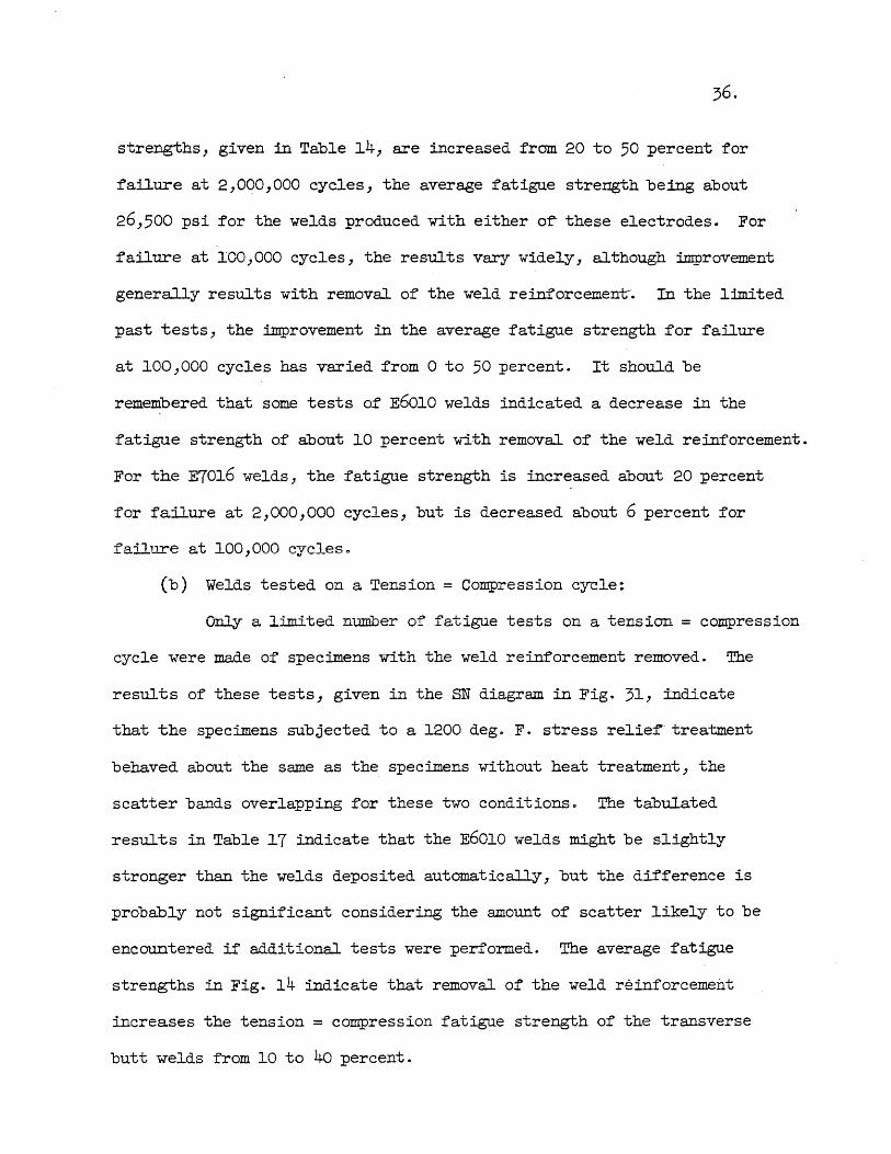
36.
strengths, given in Table 14, are increased fram 20 to 50 percent for
failure at 2,000,000 cycles, the average fatigue strength being about
26,500 psi for the welds produced with either of" these electrodes. For
failure at 100,000 cycles, the results vary widely, although improvement
generally results with removal of the weld reinforcemen~. In the limited
past tests, the improvement in the average fatigue strength for failure
at 100,000 cycles has varied from ° to 50 percent. It should be
remembered that some tests of E6010 welds indicated a decrease in the
fatigue strength of about 10 percent with removal of the weld reinforcement.
For the E70l6 welds, the fatigue strength is increased about 20 percent
for failure at 2,000,000 cycles, but is decreased about 6 percent for
fa;lure at 100,000 cyclese
(b) Welds tested on a Tension = Compression c~le:
Only a llmited number of fatigue tests on a tension = compress~cn
cycle were made of specimens with the weld reinforcement removed. Tbe
results of these tests, given in the SN diagram in Fig. 31, indicate
that the specimens subjected to a 1200 dego F. stress relie~-treatment
behaved about the same as the specimens without heat treatment, the
scatter bands overlapping for these two conditions 0 The tabulated
results in Table 17 indicate that the E60l0 welds might be slightly
stronger than the welds deposited automatically, but the difference is
probably not significant considering the amount of scatter likely to be
encountered if additional tests were performed. The average fatigue
strengths in Fig. 14 indicate that removal of the weld reinforcement
increases the tension = compression fatigue strength of the transverse
butt welds from 10 to 40 percent.

·v. REVIEW OF PAST FATIGUE TESTS OF TRANSVERSE BUTr WELDS IN SILICON
STEEL .AND m LOW ALLOY HIGH TENSILE STEEL
16. Scope of Investigation
Only a very limited number of fatigue tests have been made of I
transverse butt welds in structural steels other than plain carbonASTM A7
steels. Two series of fatigue tests have been conducted of transverse
butt welded joints in silicon steel and three series of tests of low
alloy high tensile steels 0 One additional series of tests has been made
of a transverse butt welded joint connecting an A7 steel to a low alloy
high tensile steel~
The chemical analyses and the physical properties of the steels
used in the past tests are presented in Table 180 The data in this table
indicate that the ductility and the tensile strength of the two types
of steel are about the same, but the yield point of the silicon steel
is about 50,000 psi compared to a yield point of from 55,000 psi to
60,000 psi for the low alloy high tensile steelso A direct comparison
cannot be made of the fatigue strength of the two types of steel because
the silicon steel was tested on a O-tension cycle, whereas the low alloy
steel was tested on a tension = compression cycle. If one assumes that
the tension = compression fatigue strength is 60 to 70 percent of the
* O-tension value , the fatigue strength corres:ponding to failure at
2,000,000 cycles for the low alloy high tensile steel would be
* See Section 14.

38.
38,000 psi to 44,000 psi on a O-tension cycle, compared to 36,000 psi
~or the silicon steel. The fatigue strength for failure at 2,000,000
cycles for the plain carbon ASTM A7 steel used in the past fatigue tests
varied from 30,000 psi to 55,000 psi. Thus, the silicon steel has about
the same fatigue strength as the A7 steels, whereas the low alloy high
tensile steel has a fatigue strength which may be about 10 percent
greater than that of the A7 steels.
17. Review of Past Fatigue Tests of Transverse Butt Welds in Silicon Steel
The results of the fatigue tests of the transverse butt welds
in silicon steel are given in Table 19 and in Fig. 320 Three specimens
were tested in the as-welded condition and three with the weld reinforcement
removed. The results of the tests indicate that the removal of the weld
reinforcement did not improve the fatigue behaviour of the joint, the
average fatigue strength corresponding to failure at 2,000,000 cycles
being about 25,000 psi for both series of testso The results of the
similarly prepared welds in plain carbon A7 steels, sunnnarized in Table
14, showed that the average O-tension fatigue strength corresponding to
failure at 2,000,000 cycles ranged from 17,000 psi to 24,000 psi in the
as-welded condition, and from 26,500 psi to 29,000 psi with the weld
reinforcement removed 0 Thus, the butt welds in silicon steel have
average fatigue strengths which are equal to or less than those of the
butt welds in plain carbon steel 0
The ratio of the yield point of the silicon steel to that
of the plain carbon A 7 steels was approximately 104 (50, 000 ps i/3 5 , 000 ps i) ,
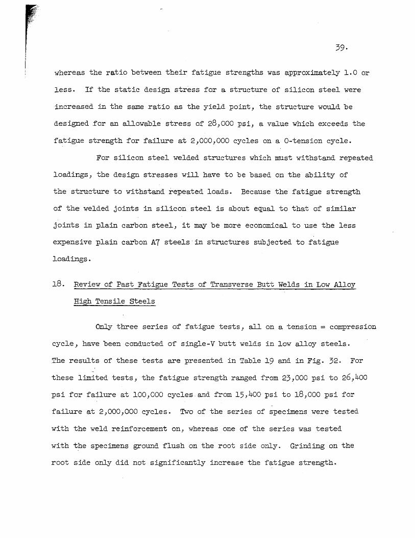
whereas the ratio between their fatigue strengths was approximately 1.0 or
less. If the static design stress for a structure of silicon steel were
increased in the same ratio as the yield point, the structure would be
designed for an allowable stress of 28,000 psi, a value which exceeds the
fatigue strength for failure at 2,000,000 cycles on a O-tension cycle.
For silicon steel welded structures which must withstand repeated
loadings, the design stresses will have to be based on the ability of
the structure to withstand repeated loads. Because the fatigue strength
of the welded joints in silicon steel is about equal to that of similar
joints in plain carbon steel, it may be more economical to use the less
expensive plain carbon A7 steels' in structures subjected to fatigue
loadings.
18. Review of Past Fatigue Tests of Transverse Butt Welds in Low Alloy
High Tensile Steels
Only three series of .fatigue tests J all on a tension = compression
cycle, have been conducted of single-V butt welds in low alloy steels.
The results of these tests are presented in Table 19 and in Figo 32. For
these limited tests, the fatigue strength ranged from 23,000 psi to 26,400
psi for failure at 100,000 cycles, and from 15,400 psi to 18,000 psi for
failure at 2,000,000 cycles. Two of the series of specimens were tested
with the weld reinforcement on, whereas one of the series was tested
with the specimens ground flush on the root side only. Grinding on the
root side only did not significantly increase the fatigue strength.
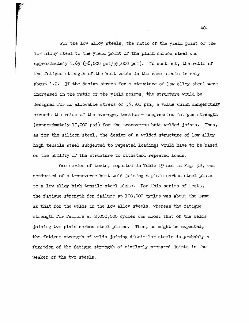
40.
For the low alloy steels, the ratio of the yield point of the
low alloy steel to the yield point of the plain carbon steel was
approximately 1.65 (58,000 psi/35,OOO psi). In contrast, the ratio of
the fatigue strength of the butt welds in the same steels is only
about 1.2. If the design stress for a structure of low alloy steel were
increased in the-ratio of the yield points, the structure would be
designed for an allowable stress of 33,500 psi, a value which dangerously
exceeds the value of the average, tension = compression :fatigue strength
(approximately 17,000 psi) for the transverse butt welded joints. Thus,
as for the silicon steel, the design of a welded structure of low alloy
high tensile steel subjected to repeated loadings would have to be based
on the ability of the structure to withstand repeated loads.
One series of tests, reported in Table 19 and in Fig. 32, was
conducted of a transverse butt weld joining a plain carbon steel plate
to a low alloy high tensile steel plate. For this series of tests,
the fatigue strength for failure at 100,000 cyc~es was about the same
as that for the welds in the low alloy steels, whereas the fatigue
stre~h for failure at 2,000,000 cycles was about that of the welds
joining two plain carbon steel plates. Thus, as might be expected,
the fatigue strength of welds joining dissimilar steels is probably a
fun~tion of the fatigue strength of similarly prepared joints in the
weaker of the two steels.

41.
VI. SUMMARY AND CONCLUSIONS
19· Summary
It has been the purpose of the experimental program reported
herein to compare the fatigue and the static properties of butt welds
produced with the E6010 and the E70l6 electrodes. Two types of butt weld
specimens were tested~ the longitudinal butt weld was tested with the
applied stress parallel to the direction of welding, whereas the transverse
butt weld was tested with the a~plied stress perpendicular to the direction
of welding. The butt welds have been tested either with the reinforcement
on or with the reinforcement removed by grinding and were subjected to
a stress c,ycle which varied from a low tension of about 2,000 psi to a
maximum tension, which was ·of such magnitude that failure generally
occurred between 100,000 cycles and 2,000,000 cycles.
The results of the present tests are summarized in the
accomp~ing Table which gives the average fatigue strength for the E60l0
O-TENSION FATIGUE STRENGTH
E6010
fioo,OOO psi
Longitudinal Butt Welds
Reinforcement On ••••• o ••••••• 37,400 Reinforcement Ground Off •.••. 39,800
E7016 Reinforcement On •••••••..•••• 41,700 Reinforcement Ground Of'.f ••••• 48 ,300
Transverse Butt Welds
E6010 Reinforcement On .••••••....•• 34,900 Reinforcement Ground Off .•..• 33,300
E7016 Reinforcement On •••• o ••• o •••• 37,900 Reinforcement Ground Off ••.•• 35,400
f 2,000,000 psi
24,500 29,600
26,300 30,200+
24,000 2l,800
23,800+ 29,lOO+
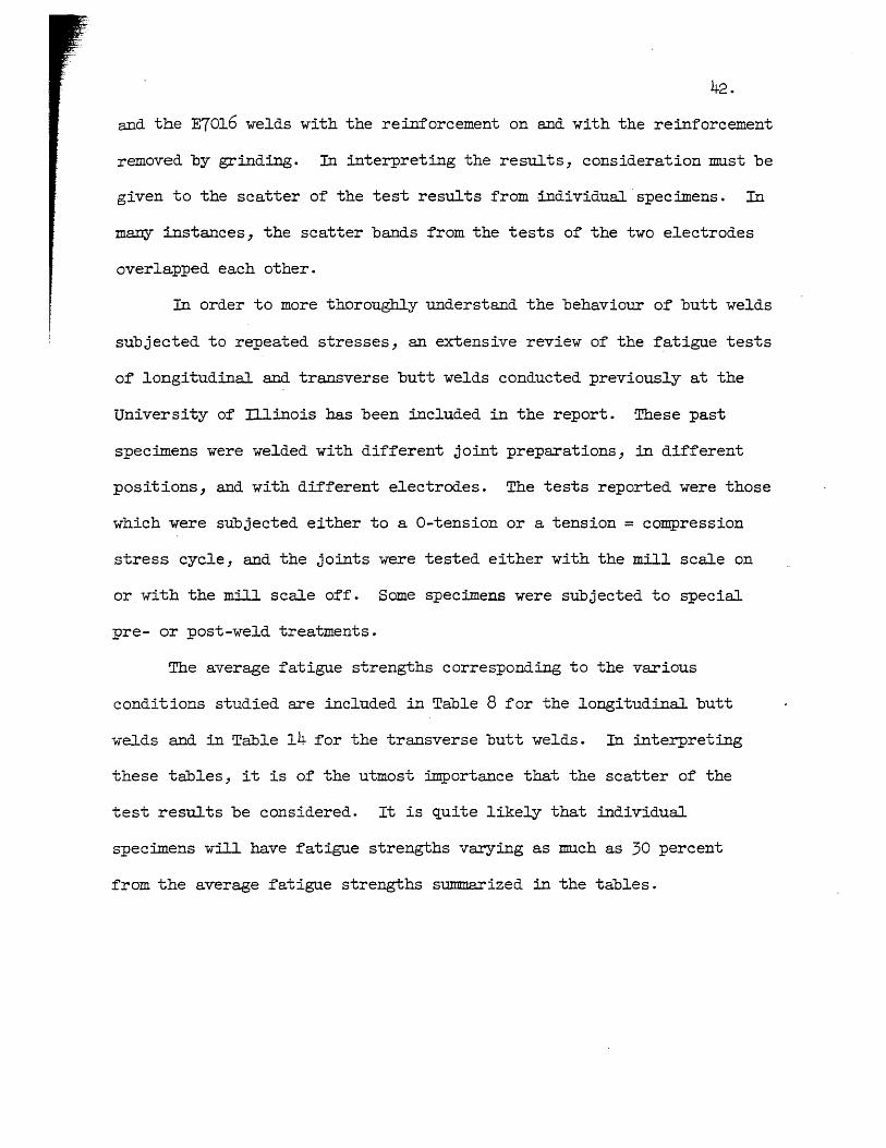
42.
and the E70l6 welds with the reinforcement on and with the reinforcement
removed by grinding. In interpreting the results, consideration must be
given to the scatter of the test results from individual specimens. In
many instances, the scatter bands from the tests of the two electrodes
overlapped each other.
In order to more thoroughly understand the behaviour of butt welds
subjected to repeated stresses, an extensive review of the fatigue tests
of longitudinal and transverse butt welds conducted previously at the
University of D.linois has been included in the report. These past
spec~ens were welded with different joint preparations, in different
positions, and with different electrodes. The tests reported were those
which were subjected either to a O-tension or a tension = compression
stress cycle, and the joints were tested either with the mill scale on
or with the mill scale off. Some specimens were subjected to special
pre- or post-weld treatments.
The average fatigue strengths corresponding to the various
conditions studied are included in Table 8 for the longitudinal butt
welds and in Table 14 for the transverse butt welds. In interpreting
these tables, it is of the utmost importance that the scatter of the
test results be considered. It is quite likely that individual
spectmens will have fatigue strengths varying as much as 30 percent
from the average fatigue strengths summarized in the tables.
20. Conclua ions
The t'ollowing conclusions are based on the results of the present
experimental. program.
(1) In the as-welded condition, the longitudinal butt welds
produced with the E7016 electrode generally had a greater O-tension
fatigue strength than the longitudinal butt welds prepared with the
E6010 electrode. For ~ailure at 100,000 cycles, the E7016 welds were
about 4,000 psi stronger than those produced with .the E6010 electrode,
but were only about 2,000 psi stronger for failure at 2,000,000 ~cles.
(2) Removal o:f the weld reinforcement significantly increased
the O-tension fatigue strength of the longitudinal butt welds produced
with both the E6010 and the E7016 electrodes. For f'ailure occurring at
100,000 cycles, the E7016 longitudinal butt welds tested with the
reinforcement ground off' were about 9,000 psi stronger than the E6010
welds, whereas for failure at 2,000,000 cycles, the two types of welds
had about the same fatigue strength.
(3) The results of all of the present transverse butt weld
tests fell within a relatively narrow scatter band. In the as-welded
condition, the welds produced with both the E6010 and the E7016 electrode
had the same fatigue strength corresponding to failure at 2,000,000
cycles, whereas the E7016 welds had a fatigue strength corresponding
to failure at 100 ,000 cycles which was about 10 percent greater than
that of the E60l0 welds.
44.
(4) With the weld reinforcement ground off, the transverse
E70l6 butt welds had a :fatigue strength which was about 6 percent
greater than that o:f the E6010 welds :for :failure at 100-,000 cycles and
about 20 percent greater for failure at 2,000,000 cycles. In general,
the removal o:f the weld reinforcement decreased the :fatigue strength
of the transverse butt welds by almost 10 percent: however, the
:fatigue strength o:f the E7016 welds :for :failure at 2,000,000 cycles was
increased by 20 percent with removal of the weld reinforcement.
The following conclusions are based on the results of the
re-evaluation o:f the past and the present :fatigue tests of transverse
butt welds in pl~in carbon ASTM A 7 steels.
(1) ~ large amount of' scatter was encountered in the past
fatigue tests of transverse butt welds; it is likely that the :fatigue
strength o:f an individual specimen will vary as much as 30 percent from
the average fatigue strength. For the welds deposited in the flat
position, the range in the average O-tension fatigue strength was from
30,800 psi to 37,900 psi for failure at 100,000 cycles and from
20,000 psi to 23,800 psi for failure at 2,000,000 cycles. Individual
specimens are likely to have a O-tension fatigue strength as low as
15,000 psi for failure at 2,000,000 cycles. For a ° to 20,000 psi
stress cycle, the transverse butt welds failed after as few as 200,000
cycles of loading or resisted as many as 8,000,000 cycles without
:failing.
r
(2) The scatter for the specimens tested on a tension =
compression cycle was even greater than that for a a-tension cycle.
Generally, the tension = compression fatigue strength was about 60 to 70
percent of the O-tension values. The lowest test result on a tension =
compression cycle corresponds to a fatigue strength of about 14,000 psi
for failure at 100,000 cycles and about 9,000 psi for failure at
2,000)000 cycles.
(3) The welds deposited in the flat position had a significantly
greater fatigue strength than those deposited in the horizontal or
vertical position.
(4) With the exception of the tests of the as-welded E6ol0
specimens tested on a O-tension cycle, there was no consistent correlation
between the location of failure and the fatigue strength. The lower
O-tension Iatigue strength of the E60l0, as-welded specimens were
generally associated with failure in the weld metal.
(5) Welds prepared with the E6ol3 or the E70l6 electrodes had
greater fatigue strengths than those produced with the other electrodes
tested. The welds produced with automatic procedures were among those
having the lower fatigue strengths.
(6) Neither peening of each pass nor heat treating the
completed weld increased the fatigue strength.
(7) Removal of the weld reinforcement generally, but not
alw~sJ resulted in an increase in the fatigue strength. The increase
in the fatigue strength varied considerably and was as great as 50 percent
in some instances 0

46.
The following conclusions are based on the results of the re
evaluation of the :past transverse butt weld fatigue tests in silicon
steel and in low alloy high tensile steel.
(1) The butt welds in silicon steel have average f'atigue
strengths which were equal to or less than those of the butt welds in
plain carbon steelo
(2) The average fatigue strengths of the butt welds in the
low alloy high tensile steels tested were about 20 percent greater than
those of the butt welds in plain carbon steels.
(3) For both the silicon steel and the low alloy high tensile
steels tested, an increase in the yield point and the maximum. strength
may result in a much smaller or no increase in the fatigue strength of
welded joints in the steels. As a consequence, the use of silicon steel
or of low alloy high tensile steel may prove dangerous in a structure
subjected to repeated loads if the allowable design stress is increased
in the ratio of the yield point of the steel to the yield point of the
plain carbon A 7 steels.
(4) A transverse butt weld joining a plain carbon steel to a
low alloy high tensile steel is likely to have a fatigue strength equal
to that of' a similarly prepared joint in the :plain carbon steel.
(5) In view of their increased use in welded structures, it is
imperative that additional fatigue tests o.f welded joints in the various
types of low alloy high tensile steels be conducted before extensive
application of' these steels is made in welded structures subjected to
repeated loadings. The very limited, past :fatigue tests of transverse
butt welds in low alloy high tensile steels indicate that the increase
in the fatigue strength, compared to that of simi] arly prepared trans
verse butt welds in plain carbon .ASTM A7 steels, varies :from 0 to 20
. percent, whereas there is at least a 50 percent increase in the yield
point ..
48.
BIBLIOGRAPHY
1. Harris, L. A., Matthiesen, R. B., and Sinnamon, G. K., "Effects of Hydrogen and. Related Variables on the Physical Properties of Welds on structural Steels,ft Report to the Ohio River Division Laboratories, Corps of' Engineers, U. S. Army, Contract DA-ee -017 -eng-96, Civil Engineering Studies, Structural Research Series No. 31, University of Illinois, Sept. 1952.
2. Matthiesen, R. B., and Harris, L. A., and Newmark, N. M., "Fatigue Properties o:f Weld Metal", Welding Journal, V. 32, N. 9, pp. 441s-453s, 1953·
3. Wilson, W. M., Munse, W. H., and Snyder, I. S., flFatigue Strength ' of" Various Types of" Butt Welds Connecting Steel Plates U
, University of" illinois Engineering Experiment Station, Bulletin Series No. 384, University of Illinois, March 1950.
4. Wilson, W. M. and Wilder, A. B., "Fatigue Tests of Butt Welds in structural Steel Plates n, University of illinois Engineering Experiment Station, Bulletin Series No. 310, University of illinOis, Jan. 1939.
5. Wilson, W. M., Bruckner, W. H., Coombe, J. V., and Wilde, R. A., ttFatigue Tests of Welded Joints in structural Steel Plates II, University of illinois Engineering Experiment Station, Bulletin Series No. 327, University of' illinois, Feb. 1941.
6. Wilson, w. M., Bruckner, W. H., McCrackin, Jr., T. H., and Beede, H. C., "Fatigue Tests of' Commercial Butt Welds in structural Steel Plates", University of' lllinois Engineering Experiment Station, Bulletin Series No. 344~ University of lllinois, Oct. 1953.
7. Wilson, W. M., Bruckner, W. H., Duberg, J. E., and Beede, H. C., "Fatigue Strength of Fillet-Weld and Plug-Weld Connections in Steel structural Members fl, University of illinois Engineering Experiment Station, Bulletin Series No. 350, University of illinois, March 1944.

TABLE l
CHEMICAL COMPOSITION OF STEEL PLATE , SPECIMEN CHEMICAL CONTENT TIl PERCENT
NUMBER C Mn P S Si
HT4 0.l8 0.68 0.016 0.039 0.03
HTl9 0.l6 0.68 O.Ol~ 0.039 0.04
HT34 0.l8 0.68 0.ol6 0.039 0.03
Average O.l7 0.68 o.ol6 0.039 0.03

TABLE 2
PHYSICAL PROPERTIES OF STEEL PLATE
STANDARD 8 IN. GAGE LENGTH TENSILE COUPON
UPPER TENSILE PERCENT PERCENT SPEC:IMEN YmLD STRENGTH ELONGATION REDUCTION
NUMBER STRENGTH IN 8 IN. OF AREA psi psi
PLATE 10
liT3 33,500 57,800 33 63 liT 5 32,900 57,900 33 64 BT13 32,700 57,800 33 61 HT15 31 z800 58z100 33 63
Average 32,700 57,900 33 63
PLATE 9
HT18 33,800 57,400 32 61 HT20 32,900 .56,200 31 63 HT23 31,800 57,300 32 63 HT25 33,500 57,000 32 62 -
Average 33,000 57,000 32 62
PLATE 8
HT32 32,300 56,700 31 62 HT36 31,100 55,500 33 60 HT40 32,400 57,000 34 63 HT43 32 z800 56z400 34 62
Average 32,100 56,400 33 62
PLATE 7 HT49 34,600 58,200 33 61 HT54 34z400 59 z000 32 62
Average 34,500 58,0-600 33 /-
b2
PLATE 6
HT59 36,800 58,300 33 58 m:62 35,700 57,600 34 61 -
Average 36,300 58,000 34 60
AVERAGE OF .ALL TESTS
33~300 .57·400 33 62

TABLE 3
WELDING PROCEDURES
OPEN CIRCUIT ELECTRODE DIAMETER CURRENT VOLTAGE VOLTAGE
in. amp volts volts
Transverse Butt Welds
E6010 first pass 3/16 125 25 81 2-6 pass 3/16 160-170 26 83
E7016 first pass 3/16 145 20 82 2-6 pass 3/16 200 20 83
Lon~itudinal Butt Welds
E6010 first pass 3/16 135 24 85 2-6 pass 3/16 150-160 25 85
E7016 first pass 3/l6 l65 20 84 2-6 pass 3/l6 200 2l 86
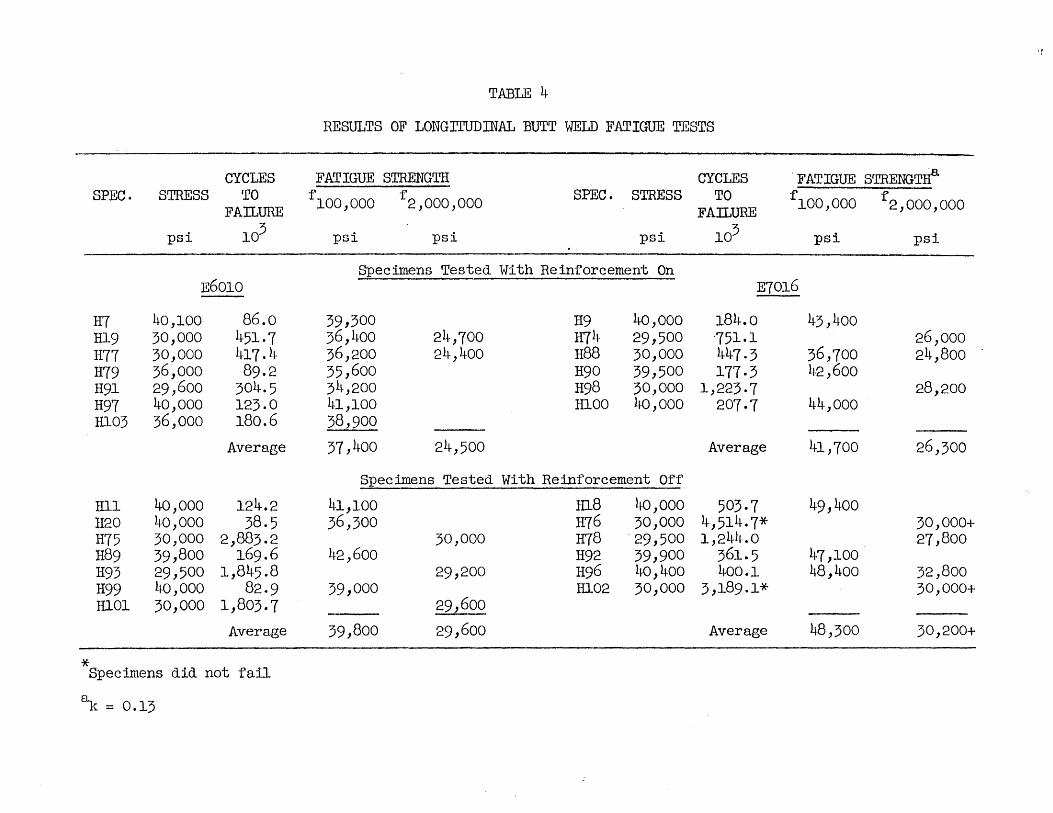
'r
TABLE 4
RESULTS OF LONGITUDINAL BUTT WELD FATIGUE TESTS
CYCLES FATIGUE STRENGTH CYCLES . FATIGUE STRENGTrf SPEC. STRESS TO f 100,000 f SPEC. STRESS TO f 100,000 f
FA~URE 2,000,000
FAlLURE 2,000,000
psi 103 psi psi psi 103 psi psi
Specimens Tested With Reinforcement On E6010 E7016
H7 40,100 86.0 39,300 H9 40,000 184.0 43,400 Hl9 30,000 451·7 36,400 24,700 H74 29,500 751.1 26,000 H77 30,000 417.4 36,200 24,400 H88 30,000 447.3 36,700 24,800 H79 36,000 89.2 35,600 H90 39,500 177·3 42,600 H91 29,600 304.5 34,200 H98 30,000 1,223·7 28,200 H97 40,000 123.0 41,100 HlOO 40 ,000 207·7 44,000 Hl03 36,000 180.6 38,900
Average 37,400 24,500 Average 41,700 26,300
Specimens Tested With Reinforcement Off
Hll 40 ,000 124.2 41,100 IUS 40 ,000 503·7 49,400 H2O 40,000 3S.5 36,300 H76 30,000 4,514.7* 30,000+ H75 30,000 2,883.2 30,000 m8 . 29,500 1,244.0 27,800 H89 39,800 169.6 42,600 H92 39,900 361.5 47,100 H93 29,500 1,845.8 29,200 H96 40,400 400.1 48,400 32,800 H99 40,000 82·9 39,000 Hl02 30,000 3,189.1* 30,000+ Hl01 30,000 1,803.7 29,600
Average 39,800 29,600 Average 48,300 30,200+
* Specimens did not fail
~\. = 0.13

TABLE 5
RESULTS OF PLAIN PLATE FATIGUE TESTS
CYCLES FATIGUE STRENGTIf' SPEC. STRESS TO f'100,000 f'
FAILURE 2,000,000
psi 103 psi psi
Mill Scale On
HIO 35,500 1,508.0 35,200 H46 40,000 450.3 33,000 H49 37,000 1,078.3 34,100 H58 37,200 1,627.2 36,200
Average 34,600
Mill Scale Of'f'
H5l 39,000 810.9 34,700 H56 37,400 . 1,137·5 34,800 H61 36,400 3,454.1* 36,400+
Average 35,300+
~ = 0.18
* S~ecimen did not fail

~~ABLE 6
_ LOCATION OF INITIATION OF FATIGUE FRACTURES IN LONGITUDINAL BUTI' WELD SPECIMENS
WELDS DEPOSITED WITH E6010 ELECTRODE WELDS DEPOSITED WTIH E7016 ELECTRODE
\Velds tested l,.,ith the reinforcement on
HI
Hl9
H77
H79
Defect in fracture surface, but fracture probably started at surface of weld at change of electrode.
Fra~ture started at internal defect.
Fracture starT,e(l all I:JU:J.:l0 a.ce aI' '·leld. Defects in fracture surface.
Fracture started at surface of 1,veld. Defects in fracture surface.
h;jJ. Fracture started at. surface of w'eld at change of electrode. Defect in fracture surface.
H97 Fracture started at surface of 1-Teld at change of electrode. Defects in fracture surface.
Hl03 Fracture started at surface of weld at change of electrode. Defects in fracture surface.
H9 H74'
H88
H90
Fracture started at surface of weld.
Fracture started at surface of '\-leld at change of electrode ..
Fracture started at surface of weld at change of electrode.
Fracture started at surface of weld at change of electrode.
H98 Fracture started at surface of weld.
HIOO Fracture origin not determined. Specimen was not pulled statically because weld joining test section and pull head failed. Fracture occurred at a change of electrode.
Welds tested with the reinforcement removed
Hll Fracture started at internal defect. Bl8 Fracture started at surface of vleld. H2O Fracture started at internal defect. H76 Specimen did not fracture. H75 Fracture started at internal defect. H78 Fracture started at surface of weld. H89 Fracture started at internal defect. H92 Fracture started at surface of weld. H93 Fracture started at internal defect. H96 Fracture started at defect in weld at surface. H99 Fracture started at internal defect. HI02 Specimen did not fracture. mOl Fracture started at internal defect.
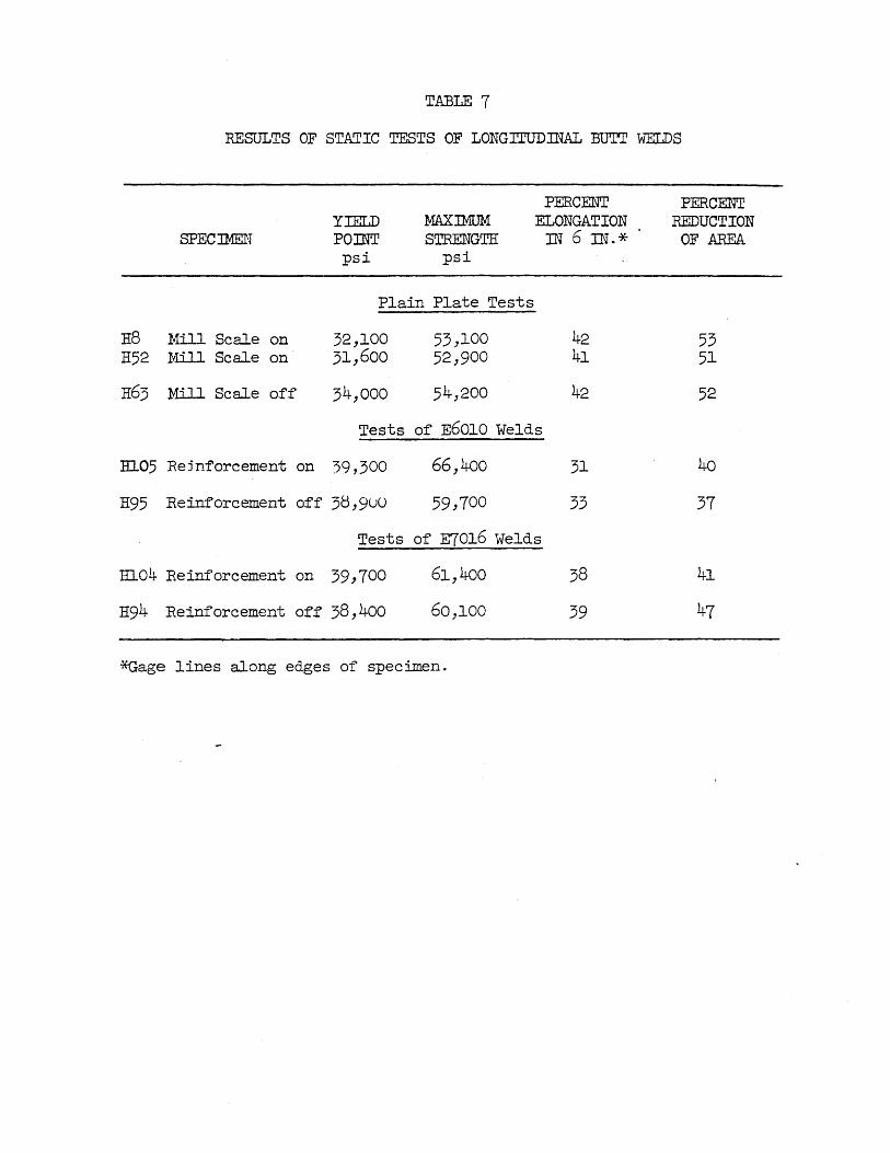
TABLE 7
RESULTS OF STATIC TESTS OF LONGITUD:rnAL :BUTr WELDS
PERCENT PERCENT YIELD MAXIMUM ELONGATION REDUCTION
SPECJMEN POnn' STRENGTH IN 6 IN.* OF AREA psi psi
Plain Plate Tests
H8 Mill Scale on 32,lOO 53,100 42 53 H52 Mill Scale on 31,600 52,900 4l 5l
H63 Mill Scale off 34,000 54,200 42 52
Tests of E60l0 Welds
Hl05 Rejnforcement on 39,300 66,400 31 40
H95 Reinforcement off 3S,9uU 59,700 33 37
Tests of E70l6 Welds
El04 Reinforcement on 39,700 6l,400 38 41
H94 Reinforcement off 38,400 60,100 39 47
*Gage lines along edges of specimen.
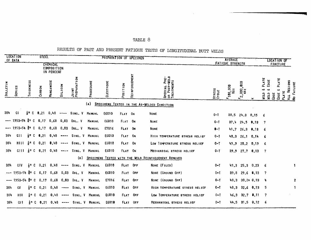
.~
TABLE 8
RESULTS OF PAST AND PRESENT FATIGUE TESTS OF LONGrTUDINAL BUTT WELDS LOCATION STEEL PREPARATION OF SPECIMEa-OF DATA AVERAGE LOCATION OF
" CH~ICAL FATIGUE STRENGTH FRACTURE C(}1POSITION IN PERCENT ...
z Z 10 lU lU..I '" '" lU
0 ffi O::lU<I) .... '" .... (I) (I) lU '" C) :z (I) <I) ;: Q.:II ... c " c
Z '" ;: W W Z 0: 0 2 0 12 0 ..I 0 ..I o 0: c ::> 0 0 0: C) CID Q. LIJ Q. - ::> (I) 2 Z Z 0 0: 0 ....... W 0 W W ~ 0 C 0 ... c 0: - 0 cto~ to 0-
.. U ..J W ... .... Lt.. 0- .., .., 000 '" -..I ;:r 0 CO U ::; ZOo. 0 0 - Z -0 .... (l)W .... (1) 0(1) '" c: c ..I ;: 0: Z -lU 0 lU (I)
o Q. -< 1.1.1..1 O:a.: O~ ~ 0 W W.... u.. :::> w c c 0 00:: 0: .... 0 w W 1.1.1 0:0 CD ... m~g~:to co (I) .... u ::E: -, Q. Q. LIJ a.. 0:: /))0:0: til; - (\.I 0 .... LL. Lt.. :w: =-=- LIJ -<:.:: -(A) SPECIMENS T!SlED IN THE AS~WELDED CONDITION
38'l GI in C 8.21 00 '+8 SING. V MANUAL E6010 FLAT ON NONE O-T 38.5 2'+.3 0.15 6
~-~ 1953coS\ i" C 00 17 0.68 00 03 OSL. V MANUAL E6010 FLAT ON NONE O-T 87.'+ 2'+.5 0.1 a 7 _ .. .., 1953-5~ In C 00 17 0.68 00 03 OSlo V MANUAL £1016 FLAT ON NONE I-T if1.7 26.8 0.18 6
38'+ Gil ~" C 00 21 0.'+8 SING. V MANUAL E6010 FLAT ON HIGH TEMPERATURE STRESS RELI!F O-T '+0.8 26.1 0.1'+ 6
38lt HIli !" C 0.21 D0 48 SING. V MANUAL E6010 FLAT ON Low TEMPERATURE STRESS RELIEF O-T 49.' 28.2 0.19 6
384 Gill !" C 6,,21 00 48 SING. V MANUAL E6010 FLAT ON MECHANICAL STRESS RELIEF O-T 39.9 27.7 0.13 7
(a) SPECIMENS TESTED WITH THE WELD REINFORCEMENT R8HOVED
38 .. GIV ~" C 00 21 0,,'+8 SING. V MANUAL E6016 FLAT OFF NONE (FILED) O .. T "9.3 25.3 0.23 6
--- 1953-5" in c 0 .. 17 0.68 0,,03 Dal. V MANUAL E6010 FLAT OFF NONE (GROUND OFF) O-T 99.8 29,6 8.13 7
....... 1953~54 in C 0 .. 17 00 68 00 03 OBl .. V MANUAL E7016 FLAT OFF NONE (GROUND OFF) O-T '+8.3 30.2+ 0.19 \ 2
384 GV ~" C 00 21 0."8 SING. V MANUAL E6010 FLAT OFF HIGH TEMPERATURE STRESS RELIEF O .. T "8.3 32.6 00 13 S
384 HIV ~" C 0.21 00 48 SING. V MANUAL E6010 FLAT OFF Low TEMPERATURE STRESS RELIEF O-T 46.3 32.7 e .11 7
384 GV I l" C 0.21 0.lt8 SING. V MANUAL E601. FLAT OFF MECHANIOAl STRESS RELIEF O-T "'l.S al.5 0.12 6
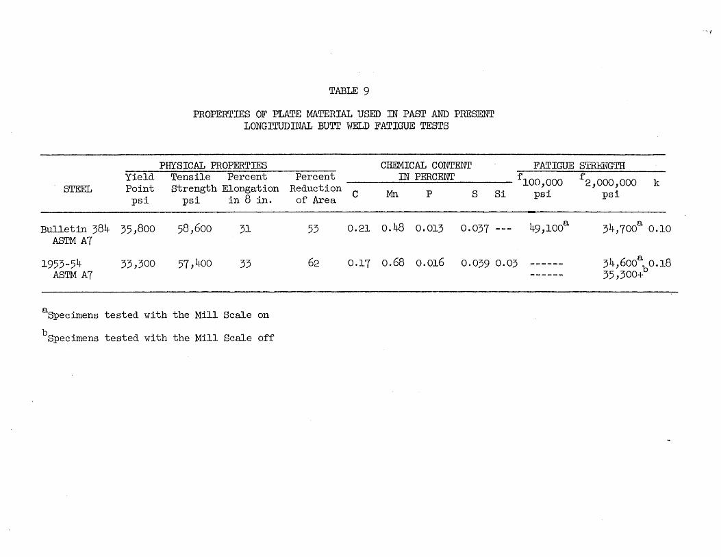
Yield STEEL Point
psi
Bulletin 384 35,800 ASTM A7
TABLE 9
PROPERTIES OF PLATE MATERIAL USED m PAST AND PRESENT LONGrruDINAL BUTr WELD FATIGUE TESTS
PHYSICAL PROPERTIES CHEMICAL CONTENT Tensile Percent Percent IN PERCENT Strength Elongation Reduction
psi in 8 in. of Area C Mn P S
58,600 31 53 0.21 0.48 0.013 0.037
FATIGUE STRENGTH f1OO,OOO f 2,OOO,OOO k
Si psi psi
49,100a a 34,700 0.10
1953-54 33,300 57,400 33 62 0.17 0.68 0.016 0.039 0.03 ------ 34 ,600ab 0.18
ASTM A7
aSpecimens tested with the Mill Scale on
bSpecimens tested with the Mill Scale off
------ 35,300+
·'·T

TABLE 10
RESULTS OF TRANSVERSE BUTr WELD FATIGUE TESTS
CYCLES FATIGUE STRENGTIf' LOCATION TO f 100,OOO f OF b
SPEC. STRESS FAILURE 2,000,000
FRACTURE
psi 103 psi psi
E60l0 z Reinforcement On
Hl2 29,400 53709 36,600 24,800 edge m4 28,000 539·4 34,900 23,600 edge R22 26,000 802.2 23,100 w.m. E26 35,000 95·3 34,800 w.m. R32 26,300 984.0 24,000 w.m. H48 36,000 53·2 33,200 w.m. H54 25,000 1,695.4 24,500 w.m.
Average 34,900 24,000
E70l6 z Reinforcement On
Hl3 29,100 354.8 34,300 edge Hl7 39,000 117.8 39,800 edge H21 26,000 1,097·0 24,000 edge H25 39,600 98,8 39,600 edge H31 24,200 1,243.8 21,800 edge H65 25,700 3,056.2 25,700+ edge
Average 37,900 23,800+
E60l0 z Reinforcement Off
H28 35,000 112·7 35,600 w.m. IDO 26,000 530.1 32,300 21,900 w.m. H40 23,400 771.0 20,700 w.m. H44 25,400 541.2 31,600 21,400 w.m .. H50 35,000 74.0 33,600 w.m. H60 23,000 2,810·9 23,000 w.m.
Average 33,300 21,800
E70l61. Reinforcement Orf
H27 32,000 179·1 34,600 w.m. H39 26,000 c 26,000+ 2,079·7 H43 35,200 177·1 37,900 w.m. H45 36,100 1,808.9 35,600 plate H57 30,500 533·7 38,000 25,700 ;'f.m. H64 30,500 118.8 31,200 w.m.
Average 35,400 29,lOO+
~ = 0.l3 b w.m. = weld metal; edge edge of weld; plate = plate away from weld =
cSpecimen did not fail

TABLE 11
RESULTS OF STATIC TESTS OF TRANSVERSE BUTT WELDS
PERCENT PERCENT YIELD MAXJMUM ELONGATION REDUCTION
SPECrnEN POINT STRESS IN 6 IN.* OF AREA psi psi
Plain Plate Tests
H8 Mill Scale on 33,000 53,100 42 53 H52 Mill Scale on 31,600 52,900 41 51 H63 Mill Scale off 34,000 54,200 42 52
Tests of E6010 Welds
H2 Reinforcement on 31,700 52,900 35 35 H62 Reinforcement o.ff 33,400 55,400 35 56
Tests of E7016 Welds
H29 Reinforcement off 33,200 54,900 33 47 H47 Reinforcement on 31,800 52,500 30 46

TABLE 12 PROPERTmS OF PLATE MATERIAL USED m PAST AND PRESENT TRANSVERSE BUTT WELD FATIGUE TESTS
PHYSICAL PROPERTIES CHEMICAL CONTENT FATIGUE STRENGTH* Yield Tensile Percent Percent IN PERCENT f 100,000 f 200 ,000 k
STEEL Point strength Elongation Reduction C MIl P S 8i psi psi in 8 in. of area psi psi
Bulletin 3l0c 31,000 51~, 500 34 61 0.15 0.50 0.024 0.022 0.06 30,300+ a 0.10
ASTM A7
Bulletin 327 31~ ,800 61,300 31 54 0.26 0.47 0.015 0.034 0.01 119,80~ 31,600+a
0.18 ASTM A7 59,600 0.18
Bulletin 31~4 ASTM A7 Series X 30,700 59,000 30 54 0.25 0.49 0.009 0.029 0.00 Series Y 29,500 62,300 29 52 0.24 0.47 0.017 0.029 0.03 Series Z 31,000 60,200 30 59 0.19 0.51 0.018 0.029 0.01 All but Above 33,600 63,300 30 51~ 0.26 0.54 0.010 0.034 0.01
Bulletin 350 ASTM A7 38,200 62,700 30 57 0.20 0.42 0.015 0.027 0.23
Bullet in 384 49,100a 34,700
a ASTM A7 36,100 58,900 31 53 0.21 o.~B 0.013 0 .• 037 ---- 0.10
1953-54 d 33,300 57,400 33 62 0.17 0.68 0.016 0.039 0.03 34,6ooa
b 0.18 ASTM A7 35,300+ 0.18
~~-Tension Stress Cycle
~einforcement on cTests reported in Bulletin 302
bReinforcement off dOrdered to American Bureau of Shipping Specification for Type B steel

Z
tW d ..J :!) al
~ a: w CI)
327 K~L
3IJIJ l
31+1+ P
31f1J S5
TABLE 13
RESULTS OF PAST AND PRESENT FATIGUE TESTS OF TRANSVERSE BUTI' WELDS
IN THE AS-WELDED CONDITION: O-TENSION CYCLE
CI) CI) w z ~ ()
:x: t-
STEEL
z o co 0: < o
w CI)
w z < (!J lZ
~
z o o .,J
en
z o .... < a:
~ : w
o 0:: -,0..
W 0: ::> o w () o 0:: a..
PREPARATION OF SPECIMEN
w o o 0:: to W
~
z o tCI)
o 0...
tZ
~ U 0:: o lL. Z
W a:
AVERAGE FATIGUE. STRENGTH
LOCATION ~ .. ·FRACTURE
10 W W..J ... I- en a:WCl) C2:)" 4; Z W a..:-I- CD O..J 00::
I Z «::) e UJ 0... ::> "'I-~ 0 ... " ... «C(J)f;: (J) 0- c- ~.., ~
o ~ 4; ~ ~ o""~ i ~ 0 0 W W ~ a1 w w a:o 0 ... ......Juu<..J 0.0::0:: 1->- - N jJ.IwoO ... ..JO .~ 01- en 0 _lL. ___ lL. ~ =-:11. W UJ .0- .cz
(A) SPEO~ENS PREPARED WITH THE E601m ELECTRODE
7/snc 09 26 O~1f7 00 01' SING a U MANUAL E6010 FLAT ON
7/8"C 00 19 00 51 00 01 DBL. V MANUAL E601Q FLAT ON
7/8nC 0.26 O~51+ 00 01 DBlo V MANUAL E6010
7/anc 00 26 0 0 51+ 00 01 DBl. V MANUAL E6010
FLAT ON
Ft.AT ON
NONE
NONE (ICOf-to1ERO I AL-SHOP)
NONE (CO,..,EROIAL-SHOP)
NONE (COt-f.1EROIAl-SHOP)
3a o ' 22 .. 5 0.13
30 .. 8 21Q2 0.13 5
al+ o l 21 .. 3 00 19
30,7 0.13 . 3
a 3
5
--- 195a~51+ jw C 00 17 0.68 oola OSlo V MANUAL E6010 FLAT ON NONE
O-T
O-T
O-T
O-T
O-T
O-T
o-T I-T
O-T
O-T
a~.9 2~.,O 0.13 5
32 .. 9 17.0 0 .. 19
18.5 e.19
17.2 0.13
27.a 19.9 0.13
2
3 5
2
31+1+ A 7/8"C 00 26 0.,5" oocn DBlo V MANUAL E6010 FLAT ON . OVERHDo
34IJ MH 7/a"c 00 26 00 54 00 01 OSlo V MANUAL E6010 HORIZ o ON
344 NH 7/8nC 00 26 00 54 00 .1 DOLo V MANUAL E6010 HORIZ. ON
341+ 05,06 7/8 11C 00 26 00 51+ 00 01 OBl. V MANUAL E601a VERTo ON
VERT. ON 344 MV
31+~ NV
7/a nc 0.26 0 .. 51+ 0.01 08l. V MANUAL E6010
7/8nC 00 26 00 51+ 8,11 OBl o V MANUAL E601~ VERT., ON
NONE (COMMEROIAL-SHOP)
,NONE (COMMEROIAL-FIElD TEMP 00-1+,,0 F.)
NONE (COMMERCIAL-FIELD)
NONE (COMMEROIAl-SHOP)
NONE (COr.1ERO I A L-F I ELD TEMP. c 00 - ~OOF)
NONE (COMMEROIAl-FIELD)
18.6 8.13
O-T 23.8 0.13 3
2
2 1 . 1
a

TABLE 13 (CON'T)
RESULTS OF PAST AND PRESENT FATIGUE TESTS OF TRANSVERSE BUTT WELDS
IN THE AS-WELDED CONDITION: O-TENSION CYCLE
lOCATION STEEL--- I"REmATToffor- SPEC IMEN AVERAGE [DUTTONOf' OF DATA FATIGUE STRENGTH FRACTURE
cAtf.1lcAL COMPOSITION IN PERCENT W !i '0 W t- (I)
Z W llJ...I C (!J < z W 0 ~ o:W(I) 0 a ...I o 0:
(I) W ;: W W W o..~E 0 0 LLJ 0.. - :::>
2 (I) (I) 0: 0 Z () a .. " ...I
W W Z < ::> 0 0 0: ...I .... (/) o co 0- .a ..:J W -l- (I) Z Z Z 0 0: a 0: 0 <(1):1: (l)W .. CoO 0(1) W (X: -< W W ~ 0 ..: 0 l-<O( W .... .... !J. -01- W..J o~ o ~ a a W W .... I.L.
..J 0:: 0 al " :; ZQ. () 0 C;; z o a.. < 0:0 0 0- ..I;..J""<...I ..J i 0: Z -w 0 ~ w w W tili ~ , N WWOO..l...lO
::> w < <C 00: 0: 0 0..0:0: U. !J. 111: :w =- LLJ. LLJ 0.. coC Z
co (I) t-> (.) :L en -, 0- 0- LLJ 0.. a:: en 0"-
(B) SPEOIMEN§ PREPARED WITH THE E6012 ELEOTRODE
344 X 7/8"C 0,,25 00 49 00 00 OBLo V MANUAL E6012 FlAT ON NONE (COMMEROiAlQSHOP) O .. T 3407 2101 0.13 5 2
34'4 XX 7/8"C 00 26 00 54 00 01 OBLo V MANUAL E6012 FLAT ON NONE (COMMEROIAL-SHOP) 0-1 33.8 23 0 l 00 13 2 2 2
S4~ B 7/a flC 00 26 0,,5'4 00 01 \
OeL Q V MANUAL E6012 Fur ON NONE (COMMEROIAl-SHOP) O-T 32 0 6 20.0 0.13 2 '*
2
344 E 7/8"C 0,,26 00 54 ooOt OBLo V MANUAL E6012 VERi. ON NONE (COMMERCIAL-SHOP) O .. T 29.8 18.1 0.13 2 4 1 1
(0) SPECIMENS PREPARED WBTH THE ,E6013 ELEOTROEE
344 C 7/8 ff C 00 26 00 5'4 0,,01 OSLo V MANUAL E6013 FLAT ON NONE (COMMEROIAL-SHOP) O-T 35 0 2 20.7 0.13 1 .. 3 1 OvERHD.
3 .. 4 F 7/S"C 00 26 0,,54 00 01 OSLo V MANUAL E6013 VERT. ON NONE (COMHE~OIAL~SHOP) O.,.T 3L6 21.3 00 13
(D) SPEOIMENS PREPARED WITH THE E6020 ELEOTRODE
34'4 T6 7/SnC 00 26 00 54 00 01 DBLo V MANUAL E6020 FLAT ON NONE (COr-t1ERCIAL"SHOP) O~T 32.0 ___ m
0.18 1
(E) SPEOIMENS PREPARED WITH THE E6030 ELECTRODE
a .... y 7/8 11 C 00 2" 00 "7 00 03 SING o U MANUAL E6030 FUT ON NONE (COMMEROIAL-SHOP) O-T 31.6 21.5 0.13 7
34'4 R 7/811 C 0,,26 0.5" 00 01 OBLo V MANUAL E6030 FLAT ON NONE (COMMEROIAL-SHOP) O-T 34.9 22.2 0.13 3 3
344 U4,U6 7/811 C 00 26 0,,54 00 01 OSL" V MANUAL £6030 FLAT ON NONE (COMMEROIAL-SHOP) O-T 2702 19.8 0.13 2
344 G5 7/S"C 0,,26 0.5" 0.01 SING" II MANUAL E6030 FLAT- ON NONE (COMMEROIAL-SHOP) O-T 28.7 19.4 0.13 2 E6010 OVERHEAD
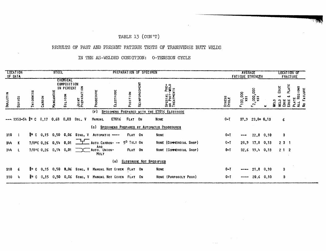
TABLE 13 (CON'T)
RESULTS OF PAST AND PRESENT FATIGUE TESTS OF TRANSVERSE BtYIT WELDS
rn THE AS-WELDED CONDITION: O-TENSION CYCLE
roc-ATfON---~~'-U_-~~--STEE[- ---- _u_ PREPARATlONOF--SP£C1MEN AVERAGE LOCAT ION OF OF DATA FATIGUE STRENGTH FRACTURE CHEMIcAL -_ ..
z tW .J .J
~
CI) W
0:: W
CI)
(I) CI) w z )o! (.)
:z: t-
Z o Ql 0: <
U
---, 1953-54 in c 0.17
310 in C 0.15
944 K 7/8"C 0.2£)
3lf4 l 7/8"C 0.26
310 6 I" C 0.15
310 4 in C 0.15
COMPOSITION ~ I 0
IN PERCENT ~ ~ ~ iii CI) w - w W [il a.:' r CI) ... 0:: 0 Z (,) I ~ W Z C :J 0 0 0:: ..Jt-W z 0 IX: 0 0:: - 0 CCI)::I: C (,) t-< W r t- lI. -at-
~ ::i =: ~ g ~ ~ ~ ~o. ~ .~ _ 00: Q: ..J 0 W 0.0:0:: :I: CI) -,0. 0... Wo...o::: Cl)Ot-
(F) SPECIMENS PREPARED WITH THE E7016 ELECTR2~
00 68 0.03 DSL. V MANUAL E7016 FLAT ON NONE
(c) SPEOIMENS PREPARED BY AUTOMATIO PROOE~
00 50 CloD£) SINO. V AUTOMATIC-- FLAT ON NONE
00 54 00 01 ~ AUTO. CARBON- -- 50 TILT ON NONE (COMMERCIAL SHOP) ARO
O.51t 00 01 =X=AUTO. UNION- FLAT ON NONE (COr+t£RCIAL SHOP) MELT
(H) ELEGTRODE NOT SPEOIFIED
00 50 0.06 SINC. V MANUAL NOT GIVEN . FLAT ON NONE
0.50 0.06 SING. V MANUAL NOT GIVEN FLAT ON NONE (PURPOSELY POOR)
CI) (l)W W.J a:o );it;
0-1
O-T
O-T
o-T
O-T
0-1
0 0 (l) -
.. (I) O),C 0
~
37.9
28.9
32".6
0 0 0 .. 0-0(1) 0).: .. N
lI. ~
23.8+ 0.13
22.8 0.10
17.8 0.13
19.4 0.13
21.8 0.10
20.6 0.10
w W t- CI)
" j z w 0 o a: LU 0. - :;)
CI .J e(! ~ W
W 0: c oowwt- '-L ..J.J8"c.J WW ~.J..Jo =-:.W 0...<2
6
3
2 3
2 1
3
a
2
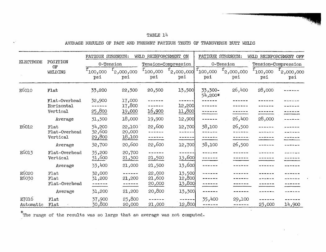
TABLE 14
AVERAGE RESULTS OF PAST AND PRESENT FATIGUE TESTS OF TRANSVERSE BUTT WELDS
FATIGUE STRENGTH: WELD REINFORCEMENT ON FATIGUE STRENGTH: \iELD REINFORCEMENT OFF ELECTRODE POSITION O-Tension Tension=Compression O-Tension Tension=Compression
OF flOO,ooo . f ° flOO,OOO f f 100 ,OOO f . flOO,OOO f
WELDmG 2,000, 00 2,000,000 2,000,000 2,000,000 psi psi psi psi psi psi psi psi
E6010 Flat 33,200 22,300 20,500 13,500 33,300- 26,400 28,000 ------54,200*
Flat-Overhead 32,900 17,000 ------ ------ ------ ------ ------ ------Horizontal ------ 17,800 ------ 12,200 ---_ ... - ------ ------ ------Vertical 25,800 19 z000 16z900 11,800 ------ ------ ------ ------
Average 31,300 18,000 19,900 12,900 --- ... -- 26,400 28,000 -----_.
E6012 Flat 34,200 22,100 . 22,600 12,700 38,100 26,500 ------ ------Flat-Overhead 32,600 20,000 ------ ------ ------ ------ ------ ------Vertical 29 z8oO 18z100 ------ ------ ------ ------. ------ ------
Average 32,700 20,600 . 22,600 12,700 38,100 26,500 ------ ------E6013 Flat-Overhead 35,200 20,700 ------ ------ ------ ------ ------ ------
Vertical 31,600 21,300 21,500 13,600 ------ ------ ------ ------
Average 33,400 21,000 21,500 13,600 ------ ------ ------ ------E6020 Flat 32,000 ------ 22,000 13,500 ------ ------ -_ ... _-- ------E6030 Flat 31,200 21,200 21,600 12,800 ... ----- ------ ------- ------
Flat-Overhead ------ ------ 20,000 13J800 -_ ... --- ------ - ... ---- ------Average 31,200 21 J 200 20,800 13,300 ------ -- ... --- ---_ .. - ------
E7016 Flat 37,900 23,800 -- ... --- ---- .. - 35,400 29,100 ------ ------Automatic Flat ____ ~ ___ _______30 ,~OO ____ _ g9-.l0Q~_ 21,000 12,800 ------ ------ 23,000 14 900 __ ~_ .. ~ _____________ ~ _____ .. _______ .____'-1._. __
* The range of the results was so large that an average 'Jas not computed.

-'i~
TABLE 14 (Con't)
AVERAGE RESULTS OF PAST AND PRESENT FATIGUE TESTS OF TRANSVERSE BUTr WELDS
FATIGUE STRENGTH: WELD REINFORCEMENT ON FATIGUE STRENGTH: WELD REJNFORCEMENT OFF POSITION 0 T' T' C . ELECTRODE OF - ens~on ens~on= ompress~on
WELDlNG flOO,ooo f 2 ,000,000 flOO,OOO f 2 ,000,000
O-Tension Tension=Compression
flOO,OOO f 2 ,000,000 flOO,ooo f 2 ,000,ooo psi psi psi psi psi psi psi psi
Specimens prepared with pre- and post- weld special treatments
Not Given Flat Each Pass Peened -- ... --- 22,300 ------ ------ ------ ------ ------ ------
E60l0 Flat High Temperature stress Relief 31,900 23,700 21,300 15,100 39,300- 28,000 24,500 16,600
53,300*
E6012 Flat ------ ------ ------ ------ 36,800 31,200 ------ ------High Temperature Stress Relief
Not Giyen Flat High Temperature Stress Relief 33,300 23,200 ------ ------ ------ ------ ------ ------
* The range of the results was so large that an average was not computed.

TABLE 15
RESULTS OF PAST AND PRESENT FATIGUE TESTS OF TRANSVERSE BUTT WELDS WITH THE REINFORCEMENT ON
PREPARED WITH SPECIAL TREATMENTS: O-TENSION CYCLE PROCEDURES
lOCATION STEEL -rREPAR~nmr~OfsprCTMt.ff ~- AVERAGE OF DATA
CHEMICAL FATIGUE STRENGTH
COMPOSITION IN PERCENT ... z 10
~ ffi lLI-I O::lLI(I) 0
CI) l&J ;: lLI lLI O-=r~ a z CJ) (.I) 0:: 0 Z 0 0 0 ;: w w z < ::> 0 0 0:: -It-~ 0
(I) Z Z Z 0 0:: 0 0:: ;: 0 <(.I) CJ) c - 0-lLI lLI )II: 0 < 0 !i.:~ W t- lJ... -0 (l)lLI o"~ ocn ...J
~ 0 co " ,g ,(.) - Z 00.. < W.J 0)11:
-I ;: 0:: Z ..I -lLI lLI CJ) W lLI lLI 0::0 0 .. ::> lLI -< ~ 00:: 0:: ...J 0 0..0::0:: t-)- .: N co (/) t- o (/) .., 0.. 0- W 0- 0:: (/)ot- (/)0 Il.
310 3 i" C O~15 0~50 0.06 SING o V MANUAL NOT FI~AT ON EAOH PASS PEENED O"T 22.9 GIVEN
327 IJ 7/8"e 0,,26 0.47 00 01 SING o U MANUAL t.6U', U FLAT ON 12000F STRESS RELIEF TREATMENT O"T 31.9 23.7
310 2 ,~Jt C 0.15 00 50 Ot~6 SING. V AUTO o CaN. MILO FLAT ON 12000F STRESS RELIEF TREATMENT O-T 33.3 'ARCI' STEEL
310 5 i" C 00 15 OQ50 00 06 SING. V MANUAL NOT FLAT ON 12000F STRESS RELIEF TREATMENT O-T 23.2 GIVEN
LOCATIoN OF FRACTURE
lLI lLI t- (I) CI < Z lLI 0 .J o a: W 0-
- ::l " -I e.O "'lLI~;
o 0 lLI W ... u.. rj-l"u<...J
lLIOO..l.J;i )II: :.:aUJUJO-cC'
0.10 3
0.,13 7
0.10 2
0.10 2 1

.. ~'.......,..-.,.~ , ; ·;tll .m
TABLE 16
RESULTS OF PAST AND PRESENT FATIGUE TESTS OF TRANSVERSE BUTT WELDS
WITH THE REINFORCEMENT ON TENSION = COMPRESSION CYCLE LOCAlTON STEEl PREPARATION Of SPECiMEN AVERAGE lOCATION OF OF D~rA FATIGUE STRENGTH FRACTURE
CHEMICAL COMPOSITION IN PERCENT
~ 10 W Z W W.J W t- eo a ffi g:~.~ 0 " 0< Z W
C4 W ;: W W a 0 .... 0 a:: 2 (I) (I) 0: 0 Z 0 12 0 0 l.LI 0..' c; ~ ;: W W Z < :l a 0 a:: .Jt-W 0 co. ....
(I) z z z 0 a:: 0 0:: ;: 0 !~~ (I) 0_ 0_ .,!J .,!J. W -W lIJ )t: a 0< 0 to< UJ ~ LL. (/)W ... (/) 0(4 W 0:: 0< -' ~ 0 III (j
~ .... PJ 0 0 - Z 00- < W.J ~w o .. ~ cow W t- U. ..J - a: Z 0 UJ (I) to UJ W Q:O .J.J(j (!I 0< ..J ::> w :r: < ~ ;n a 0:: 0:: ..I 0 n.a::o:: t->- ..: (\J ~ ~~ ~ci ~ 0 al CI) t- U -;) a. 0- UJ 0.. a:: Cl)Ot- CI) U LL. )I: z
(A) SPECIMENS PREPARED WITH THE E6010 ELECT RODEO AND TESTED iN THE AS-WELDED CONDITION
327 C,D 7/8"C 00 26 OalJ? 0.01 SINGo U MANUAL E6010 FLAT ON NONE TeC 22.3 l".lJ 0.13 6
3ltlt Z 7/B"C 0.19 0.51 00 01 DOLo V MANUAL E6010 FLAT ON NONE (COMMERCIAL-SHOP) T=C 20.2 13.0 6
34lJ 9 7/8"C 0026 O05lJ O()Ol DBLo V MANUAL E6010 FLAT ON NONE (COMMEROIAL-SHOP) T=C lB.B 11.B 0.13 3 2
344 54,56 7/B"C 0.26 0.54 00 01 OSLo U MANUAL E6010 FLAT ON NONE (COMMERCIAL-SHOP) T=C 21.lt 1lJ.O 3 3
950 19,25 ~II C 00 20 O.lJ2 0.23 SING o V MANUAL E6010 FLAT ON 19-25 PICKLED AND PAINTED T=C 19.9 15.8 3 lJ 40-42
34lJ MH 7/8"C 00 26 0.54 O.Dl DSl. V MANUAL E6010 HORIZ o ON NONE (COMMEROIAL FIELD T=C 13.1 3 TEMPo 00 <:' lJOOF) ,
34lJ NH 7/8"C 0026 O.5lJ 0.(;)1 DOLo V MANUAL E6010 HORIZo ON NONE (COMMEROIAL-FIELD) T=C 11.6 2 1
34lJ O~ 7/8"C 00 26 0.5'+ 00 11 OBLo V MANUAl E6010 YERT o ON NONE (COMMEROIAL-SHOP) T=C 16.9 1'04
344 MY 7/8 11 C 0 .. 26 0.54 0.01 OBL. V MANUAL E6010 V~RTo ON NONE (COMMEROIAL-~IELD T=C 13.8 3 TEMP. 10° - lJO F)
34lJ NV 7/8"C 00 26 0.5lJ 0.01 OBL. V MANUAL E6010 VERTo ON NONE (COMMERCIAL FIELD) T=C 10 0 3 2 2
(8) SPEOIMENS PREPARED WiTH THE E6012 ELECT~ODE AND TESTED IN THE AS-WELDED CONDITION
344 X 7/8"C 00 25 00 49 0.00 OBLo V MANUAL E6012 FLAT ON NONE (Cor+1EROIAL-SHOP) T=C 21.8 12.6 0.13 5
34'+ XX 7/8 t1 C 0.26 00 5'+ 0.01 OBL. V MANUAL E6012 FLAT ON NONE (COMMEROIAL-SHOP) T=C 23.5 12.B 0.13 ,. 2

TABLE 16 (CON'T)
HESULTS OF PAST AND PRESENT FATIGUE TESTS OF ~j{ANSVERSE Burr WELDS
wrrH THE REINFORCEMENT ON TENSION = COMPRESSION CYCLE
IOCAilOfr sTEEl. PITmRArnnrlWSPECTM~N -~VERAGE [OCATH>1f~Or--~
OF DATA FATIGUE STRENGTH FRACTURE CHEMICAL COMPOSITION IN PERCENT ... z to W z W W~ W t- c.o 0 ffi O:W(/) 0 (!J oC Z W
CI) W W W o..:-t- G a ~ 0 ~ z CI) II) t- o: 0 z 0 tz 0 co LLI 0.. ::l W W Z oC :;) 0 0 a: ~t-W 0 .. (!J ..J t- (/) Z Z Z 0 a: 0 a: 0 !~~ (/) 0- C!)- ~ ~ W W W ~ 0 oC 0 t-< W t- t- U. (/)w ... c.o 0(1) W 0: oC ~ 0 en (!J zo.. 0 0 z 00... oC W...J Ok .~ 0 o w W t- LL. ...J 0: 0: Z ...J -w 0 W (/) UJ -w 0:0 0 ... ~ .... (!J c.!J oC ~.
:;) W :c <C < 00: a: ~ 0 UJ 0.. a: 0: t-,... a:- N W W a a .... ~I~ co (I) ..... U :L (I) ..,0... 0.. OJ 0- 0: (1)0 ..... (l)U "" ~- =- :a OJ OJ 0...
(C:~ SPECIMENS PREPARED WITH THE E6013 ELEOTRODE AND TESTED IN THE AS-WELDED CONDITION
a~~ F ?/BIIC 00 26 0,,51+ 00 11 DSl. V MANUAL E6013 VERTo ON NONE (COM~EROIAL-SHOP) T=C 2105 13.6 .. 1 1
(D) SPEOIMENS PREPARED WITH THE E6020 ElEOTRODE AND TESTED IN THE AS-WELDED CONDITION
31+~ T~, T5 ?IBlle 00 26 0051~ 0.01 OSLo V MANUAL E6020 FLAT ON NONE (COM,"1ERO I Al-SHOP) T=C 22 0 0 13.5 3 1 1
(E) SPEOIMENS PREPARED WITH THE E6Q30 ELECTRODE AND TESTED IN THE AS-WELDED CONDITION
31J~ R ?IBIIC 0 .. 26 Oo51~ 0 0 01 DBLo V MANUAL E6030 FLAT ON NONE (COMMEROIAL SHOP) T=C 21.6 11.8 0.13 3 3
Sif4 U5 ?/BIIC 0.,26 • 0.51~ OoCl DBlo V MANUAL E6030 FLAY ON NONE (COMMEROIAL SHOP) T=C 13.7
34~ G~,G6 ?/Bnc 00 26 0.51~ 00 01 SING .. U MANUAL E6030 FLAT ON NONE (COMMEROIAL SHOP) T=C 20 0 0 13.8 2 3 E6010 OVERHDo
(F) SPEOIMENS PREPARED BY AUTOMATiC PROOEDIJRES AND TESTED IN THE AS-WELDED CONDITION
3~~ K ?/811C 00 26 O1)51~ 0 .. 01 =:t-r-r= AUTO.CBN -... SO TILT ON NONE (COMMEROIAl-SHOP) T=C 19.? 11.8 00 13 2 5 ARO
NONE (COMMEROIAL-SHOP) 0.13 31J~ L ?/Bnc 00 26 a ,,5'~ 0.01 ==x:== AUTOMAT I 0 -a FUT ON T=C 22 .. 2 19.7 3 8 UNIONMELT
(Q) ElEOTRODE NOT SPEOOFIED; TESTED IN THE AS-WELDED CONDITION'
82? C,E !tt C 00 26 Oo~'7 0 0 .1 SING o V MANUAL NOT GIVE:N
FLAT NONE NONE T=C 20 11 1 15.~ 0.10 4
(H) SPEOIMENS PREPARED WiTH THE E601D ELE[LRODE AND TESTED AFTER A 1200 DEG 2 f HEAT TREATMENT
327 A,B 7/8"C 00 26 0.47 00 01 SING. U MANUAL E6010 FLAT ON 12000F STRESS RELIEF TREATMENT T=C 21 0 315.1 0.13 5

• ·,1'" TABLE 17
RESULTS OF PAST AND PRESENT FATIGUE TESTS OF TRANSVERSE BUTT WELDS
WITH THE REmFORCEMENT REMOVED
mCAlioN SlEEt PRE~K[KTTON OF SPEclRtN AVERAGE (oeAT ION tF OF DATA
C!HOOCrc-FATIGUE STRENGTH FRACTURE
CI(X>1POS I T ION. liN PERCENT
~ 10 W Z
~ W..J W t- c.o
~ 0 a:wc.o 0 u ~ z W
(/) ILLI ;: W W 0..:''- D 0 ..J 0 a: z (/) I~ a: 0 at 0 • at G .. LIJ 0.. ' (j ::»
w ILLI 0< g 0 0 0: ...... W 0 .. ..J
t;j c.o z z :z 0 a: 0: ;: 0 !~~ (/) -- e- -.!I aiJ W :; W ~ 0 .: 0 t-.: W t- l&. Cl)W .. (/) .. c.o W 0:: ..J ~
0 a:I .c" :::; zo- o 0 - z o d-~ W..J o~ _lit o 0 W W'" L&.. ..J X 0: Z -w 0 W (/) W W D:U ., ... ~"'UU~..J ::l LLI < :~ 00: 0: ..J 0 LLI l};O:QI ... ,.. .... N o 0 ..J 0 Ol ' en t- o en -,d- d- LIJ d- o:: ot- enu l&. .. :..:: ~'LIJ LIJ t. -< .. z
(A) SPEOIMENS TESTED IN A O-TENSION CYOLE SPEOIMENS WITHOUT PRE- OR POST-VELD TREATMENTS 327 o,P ?/Bne 00 26 O;ti1 lfoOl SING o 0 RANUAL E6010 FLAT OFF NONE O"T ll8,,8 28." 0.18 4 2
327 Z 7/BIIC 0.26 Oolf7 O(,Gl SING o U MANUAl E6010 FLAT OFF NONE (GROUND OFF PERP~NDIOULAR TO t)oT 41+.5 26.3 0;18 3 lJ DIREOTION OF LOADING)
327 X 7/B"C.O,,2G 00lJ7 00 01 SING a U MANUAL E6010 FLAT OFF NONE (MAOHINED OFF AND POLISHED) O~l 5'+02 0.18 I
384 FI ~" C 00 21 00 '+8 SINOo V MANUAL E6010 FLAT OFF NONE (MAOH.NED AND FILED) O':"T 35.6 28.9 1.07 6
0="- 1953 ... 54 J" C 00 17 0 0 68 0.03 DBLo U MANUAL E6010 FLAT OFF NONE (GROUND PARALLEL TO DIREOTION O-T 33.3 21.8 0.13 6 OF'LOADING)
381+ HI ~" C 00 21 D.ll8 SINGo V MANUAl E6Q12 FLAT OFF NONE (MAOHINED OFF AND FILED) D .. T 38.1 26.5 0.12 6
~- ... 1953 ... 5lJ I" C 11017 10 68 80 03 DOL" U MANUAL E7016 FUT OFF NONE (GROUND PARALLEL TO DIREOTION D-T 35.4 29 0 1+ 0.13 4
in C OF LOADING)
310 7 00 15 0 0 50 00 16 SING o V MANUAL NOT FLAT OFF NONE (MACHINED OFF) O-T 27.9 0.18 3 GIVEN
(0) SPEOIMENS TESTED IN A TENSION = COMPRESSION CYOLE SPEC I HE~S WITHOUT SPEO I AL PRE- OR POST-WELD TREA TM'EN'TS
327 G~H 7/8f1 C 1026 eo .. 7 0,,11 SING .. U MANUAL E6118 FLAT OFF NONE (MAOHINED OFF) T=C 29 0 2 Do18 7
327 Y 7/8 11 C 00 26 00 '+7 00 11 SING. U MANUAL E6810 FLAT OFF NONE (GROUND OFF) T=C 26.8 .---- 1.18 2
344 K 7/8"C 0.26 0'054 00 .1 AUTO. CON. _ ... "" .... FLAT OFF NONE (GROUND OFF) T=C 23.0 llJ.9 2 ARC
SPEOIMENS WITH SPECIAL PA:E- OR POST-WELD TREATMENTS
327 E?F 7/8"C 0026 al o .. 7 0.01 SING .. U MANUAL E6010 FLAT OFF 12000F STJtESS RELI EF TREATMENT T=C 24.5 16.t; 1 0 18 1 3 5

TABLE 17 (CON'T)
RESULTS OF PAST AND PRESENT FATIGUE TESTS OF TRANSVERSE BUTT WELDS
WITH THE REINFORCEMENT REMOVED
-- . . AVERAGE lOCAl ION OF --..~~";;";"'--~I!Tt'1r:r-------~--~--~~~EPXR~nOrr-oF S~CIt"EN FAT IGUE STRENGTH . . FRACTURE .. LocATIoN STEEL \ OF DATA CHEMICil
z
ti ..J ..J :;)
CO
(I) LU
0: W (I)
(I) (I) LU Z ~ o :z: I-
z o m IX c: o
COMPOSITION IN PERCENT
&AI (A) LU Z c: U 2
~
z o ()
.... (I)
z o t..: 0::
t-..: ~fu 00:: -,0...
LU 0: :;) Q LU () o 0:
0...
SPEOIMENS WITH Af08T-WELD HEAT TREATMENT
327 M,N 7/8nC 00 26 0.\7 G.ll SING o U MANUAL
327 U 7/8 nG 1.26 Oo~7 0.01 SING. U MANUAL
3B~ FII I i" C 0.21 Oo~8
384 HII ~"C 0.21 0.~8
SING o V MANUAL
SING. V MANUAL
w o a 0: to LU ..J W
z o t(I)
o a..
tZ ill
ffi () IX o U. Z
W 0:::
E601. FLAT OFF
E6010 FLAT OFF
E6D1. FLAT OFF
E6012 FLAT OFF
, Q
~rn o...:.t-, z .ut-LU C:(I):J: -Oto o...\c: LU LU 0..0:0: (I) 0 ....
1200° STRESS RELIEF TREATMENT
12000 STRESS RELIEF TREATMENT
115&° STRESS RELIEF TREATMENT
11500 STRESS RELIEF TREATMENT
(I) ('oW W .... 0::0 t->(I) 0
D-T
O-T
O .. T
Ill-T
c .. o ID G .. -o e CI)
.. (I) • ~ «» ~ ca «) .. _ N "
U. u. ),t
.. 90 .. 27.8 B.18
53~3 0.18
W u a w e.G
a a
~'-~
39 0 3 29.1 l.tO ~
96.8 31.2 0.07 ~
w ... C ....
0...
e.G w W W tU U. C Q Q .... W W.o...
9
2
3
(A) Z LU o 0:
:;) C .... W 0: c
LL .... .... 0 ~Z
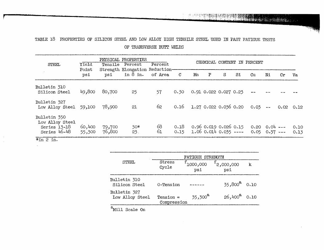
jl i!'
TABLE 18 PROPERTIES OF SILICON STEEL .AND LOW ALLOY HIGH TENSILE STEEL USED IN PAST FATIGUE TESTS
OF TRANSVERSE BUTI' WELDS
STEEL PHYSICAL PROPERTIES Tensile Percent Percent CHEMICAL CONTENT IN PERCENT Yield
Point psi
Strength Elongation Reduction--------------------------------------------------
Bullet in 310 Silicon Steel 49,800
Bulletin 327 Lmf Alloy Steel 59,100
Bulletin 350 Lmf Alloy Steel
Series 13-18 60,400 Series 46-48 55,300
*in 2 in.
psi in 8 ino of Area C Mn p S Si Cu
80,700 25 57 0·30 0.91 0.022 0.027 0.23
78,900 21 62 0.16 1.27 0.022 0.036 0.20 0.03
79,700 30* 68 0.18 0.96 0~019 0.026 0.15 0.20 76,800 23-
STEEL
Bulletin 310
61
Stress Cycle
0.15
Silicon Steel a-Tension
Bulletin 327 Low Alloy Steel Tension =
1.06 0.014 0.035 ---- 0.05
FATIGUE STRENGTH
flOOO,OOO f 2,000,OOO k psi psi
35,800a 0.10
35,300a 26,400a 0.10 Compression
~ill Scale On
Ni Cr Va
-- 0.02 0.12
0.04 --- 0.10 0·-37 --- 0.13
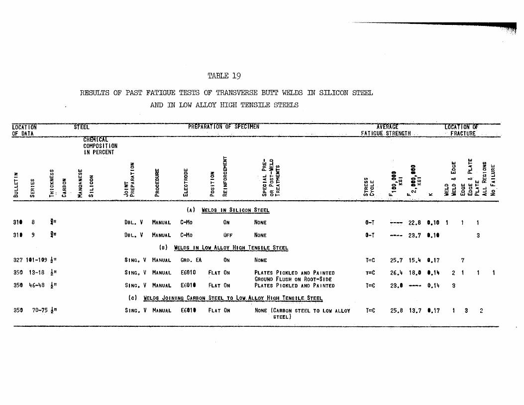
TABLE 19
RESULTS OF PAST FATIGUE TESTS OF TRANSVERSE Burr WELDS IN SILICON STEEL
AND IN LOW ALLOY HIGH TENSILE STEELS
LOCATI Off-~·- ~----SnEL pREPARATTON'OF~ SPtffifEN -~ ------·~VERAGE lOCATION Of OF DATA
(I)
Z (J) W
ti (I) z W ~
..J ~ 0
..J :l W x' en (I) t-'
311 e in 311 9 in
327 "'-'09 !" 350 13-18 ~" 350 46 .. 48 ~n
350 70 ... 75 ~"
'" (/) W z Z
0 -c: m Q 0= z <C <C u X
CHEMlCAL COMPOSITION IN PERCENT
Z 10 '0 ... el)
~ I Q Z W W.J 0 ffi ~wen
~ w 0..~!K I- 0 Z 0
~ :::» 0 0 ~ .J ... W a 0:: 0 ~~r:
~o: '" ... I- U. 0 0 Z uo..-c:
-w 0 W (I) '" W 00:: 0= ... 0 '" Q. 0:: 0:: """) 0.. 0.. L&J 0.. 0:: (I) 0 t-
(A) WELDS IN SILiCON STEEL
DOLo V MANUAL C-+1o ON NONE
DOL. V MANUAL C-Mo OFF NONE
(a) VELDS IN low ALLOY HIGH TENSlbE S~
S I NG o V MANUAL GRD. EA ON NONE
SI NGoV MANUAL E6010 FUT ON PLATES PICKLED AND PAINTED GROUND FLUSH ON ROOT-SIDE
SING. V MANUAL E6011 FLAT ON PLATES PIOKLED AND PAINTED
(0) WELDS JOINING CARBON STEEL TO Lo~ALLOY HIGH TENSIL~ STEEL
SING .. V MANUAL E6Dli FLAT ON NONE (CARBON STEEL TO LOW ALLOY 5;TEEL)
FATIGUE, STRENGTH - - "FRACTURE
e D • • .. ff:)"'-(I) o-
(l)W .. (I) .(1) W..J et~ .~ 0::0 .. 1->- - N (I) (.) u. U.
O-T 22.8
I) .. T 23.7
T=C 25.7 15.a.
r-C 26 0 4 18.1
T=C 23.'
T=C 25.8 la.7
¥
0.18
1.11
8.17
1.11J
0.14
1.17
iii
'" I- en t!J c Z W 0 .J 0 0::
L&J 0.. c; :3 eD ..:s W
"'0:: C o 0 W"'I- LL. iiJrn (St!J-c:-I
Q&}.J..J 0 =-=- UJ 0.. < ::z:
2
3
7
3
3 2
"!:;,-!~

3@ 4 1 - O· C-C II: 121- 0" --1
H 12
H 7
-I H I
H H ~ ~ 13 8
~
'- ... _/ H '0 H HT8 ~ '3 .1 14 H o 9 h
U ... . H 6 ,"/ H ~ 4 lEo ~ 15 HT9
~ 16
~-----HTIO
HI rl ~ ~ 17
FIG. I
.... DIRECTION OF ROLLING __
LOCATION OF SPECIMENS IN PARENT PLATE STEEL HJ PLATE 10, 3/4 IN. THICK

r
·0\ J co
_II "b I
(8) co.
3 crt 4'- d': 12'- o·
H H H 32 3~ 33A
H H 356 336
H ~ 31 H 51
fo I rJ C3> --~
~I r31 ~ - - - - - - - HI I ~ 281 HHI HH2 HH3 HH4 HH51
H H H
~71 38A 37A 38A
~ H H H
388 378 368
.. DIRECTION OF ROLLING ....
riG. 2 LOCATION OF SPECIMENS IN PARENT PLATE STEEL HI PLATE 9 ~ 3/4 IN. THICK
I H 21
H 22
H 23
H 24
H 25
H 26
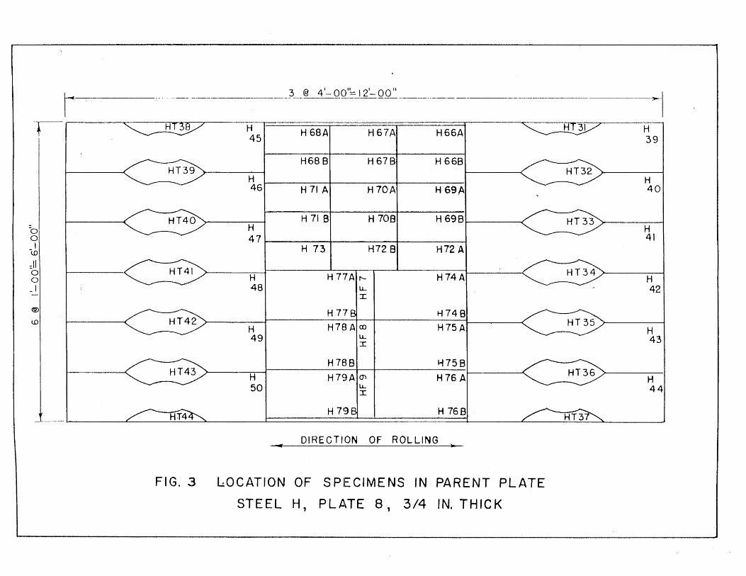
I . ----"--
rl ~7
I I
: I 0 0 I
-to
:11 <==3 0 0 - I -
(2)
to
FIG.3
~ @ 41- OOI_~J 21-QQ~ ______ . ___ . ___
H451 H 6SAI H67',t\ H66A H131
-H68 B H 6713 H 668
-H -
H G9AI ~ 46 H 71 A H 70Jt\
-
~71 H 71 BI H 7013 H 698
I ~ -H7213 H72 A H 73
H H 77A ~I H74AI ~ 48 I
H 77 H748
H H7BA CD H75AI ~ 49 u...
I
H7B8 H758
fo1 H79A (J) H76 AI ~ u... :r:
H 79 H 768
DIRECTION OF ROLLING .. lOCATION OF SPECIMENS IN PARENT PLATE
STEEL H, PLA,TE 8, 3/4 IN. THICK
I H 39
H 40
H 41
H 42
H 43
H 44
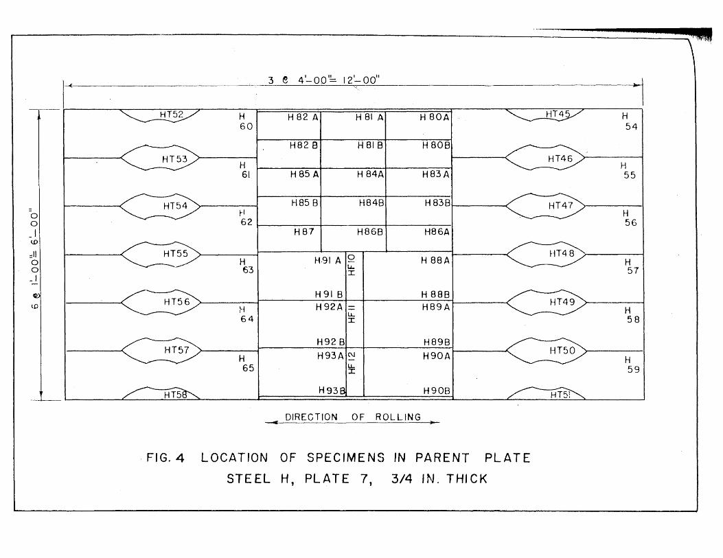
3 e 41-001~ 121-00"
~I "
----.
~of H 82 A H 81 A H 80A ~ H 54
H828 H 818 H 80B -H ~ H 61 H85 A H 84A H83A 55
~ H85 B H848 H83B
gl ~ rl I ~ H 62 56
- I H87 H868 H86A w
gl ~/ H631 H9IAI~ H 88AI ~ H .I 57
- 1
H 91 B H 888 WI , " '~~/
H I H92A = H89A ~ H lJ... 64 I 58,·
H928 H898
H651 H93A C\J H90AI ~ H
lJ.. 59 I
H938 I H90B
DIRECTION OF ROLLING =C •
. FIG. 4 LOCATION OF SPECIMENS IN PARENT PLATE
STEEL H, PLATE 7, 3/4 IN. THICK
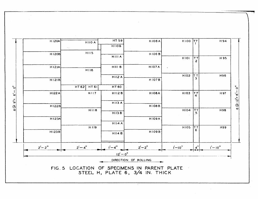
• H 120A1 H 110 A I HT 591 H 106AI H 100 ITIT I H94
HIIOB
H III A I H 120BI H 115 H 106 B
H 101 IT2TI H 95
~ H 121AI Hili B I HI07A
HI16
H 112 A I HI021T3TI H96
HI21B I H 107B
-0 HT621 HT611 HT60 0
I HI22A H 117 HI12 B H 108A HI03 TT H97 I <0 4 co
_II -'I -N ~ H 113 A @ HI22B H 108B ® c:o H 118 HI04 TT H98
<0
HII3 B 5
HI23A HI09A
HI14 A H 119 HI05 ITeTI H99
HI23BI HII4 B H 109B
~ C==2" ~I .. 2'-4" .. I~ 1'_4" 2'-2
11
:1 12'-0"
~ DIRECTION OF ROLLING ..
FIG.5 LOCATION OF SPECIMENS IN PARENT PLATE STEEL H, PLATE 6, 3/4 IN. THICK
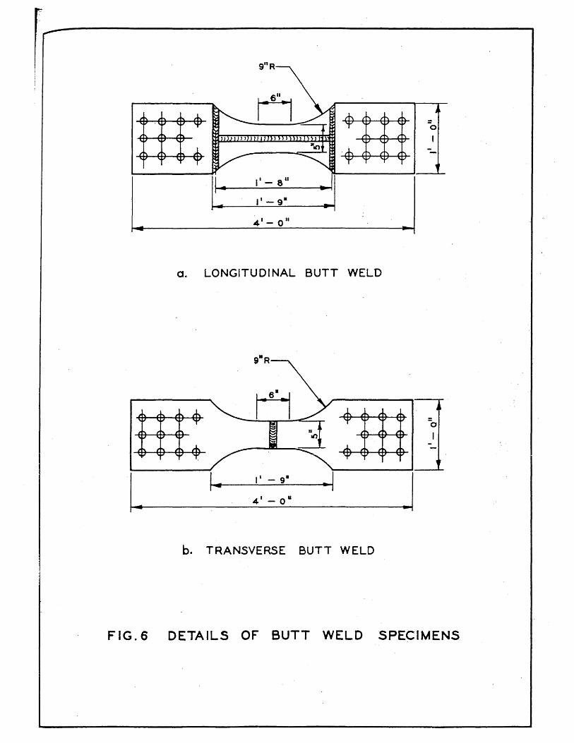
911 R
H 0
-
]: 11- 8 11
~ II - 9-
4 1- a ..
a. LONGITUDINAL BUTT WELD
b. TRANSVERSE BUTT WELD
FIG.6 DETAILS OF BUTT WELD SPECIMENS.
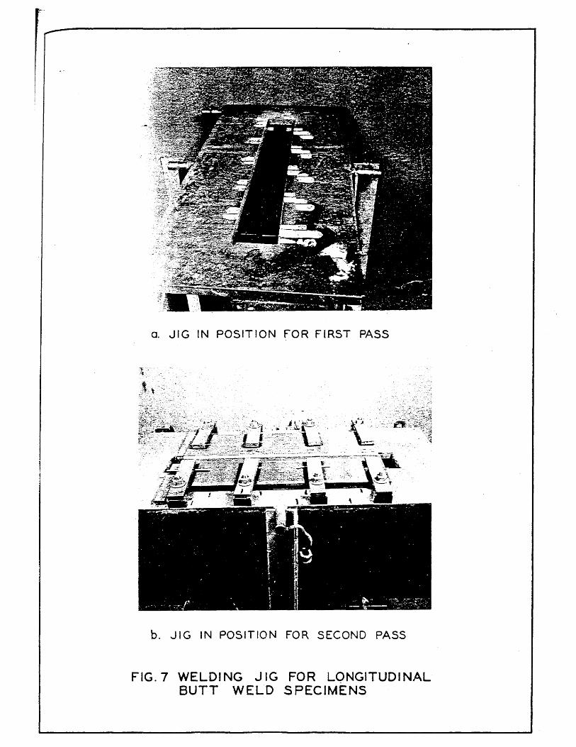
O. JIG IN POSITION FOR FIRST PASS
t ," ~t:,.~~'· .,'
"
~~i~~:t;lii~i:~C;~~h~·
b. JIG IN POSITION FOR SECOND PASS
FIG.7 WELDING JIG FOR LONGITUDINAL BUTT WELD SPECIMENS

FIG.8 DETAILS OF WELDING SEQUENCE FOR LONGll·UDINAL BUTT WELD S'PECIMENS
'r

II
FLAME-CUT ~ OUTSIDE FINAL DIMENSIONS.
4 1 - 0"
SAW-CUT AND MACHINE FOR DOUBLE V BUTT WELD.
~I
o. PREPARATION OF SPECIMEN FOR WELDING
I , I
4 11 3
11
\
5
3 2" .5"
5" 2"
2 211
4 2"
6 3 11 4"
I 7"·~ ... TRANSVERSE WELD
NOTE:
X iNDiCATES CHANGE OF" ELECTRODE.
~IRROWS iNDiCATE DiRECTiON OF WELD ING.
b. WELDING SEQUENCE
FIG.9 DETAILS OF PREPARATION OF TRANSVERSE BUTT WELD SPECIMENS
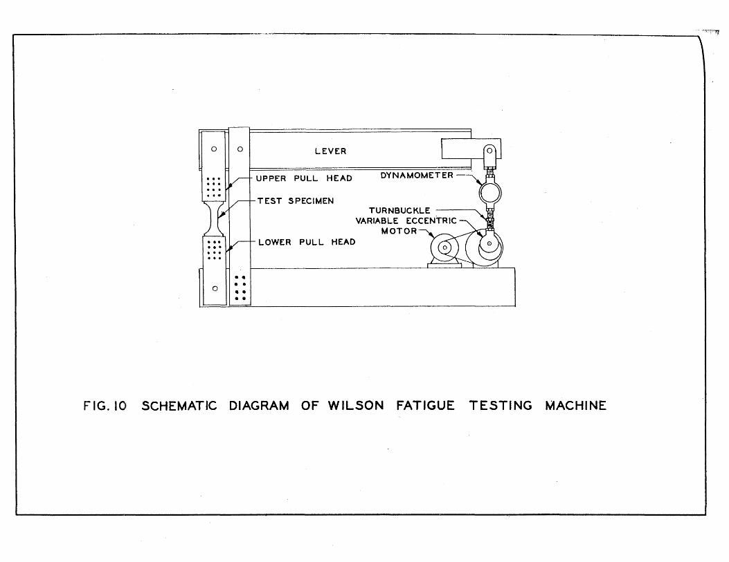
, ______________________________________________________________ ~.r~~
o II 0 I LEVER '--
UPPER PULL HEAD DYNAMOMETER
TEST SPECIMEN TURNBUCKLE
VARIABLE ECCENTRIC MOTOR
LOWER PULL HEAD •• II I ... . . .
H • •
o II·· • • • •
FIG.IO SCHEMATIC DIAGRAM OF WILSON FATIGUE TESTING MACHINE
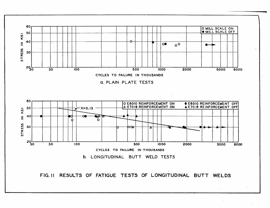
60
50 (I)
~
Z 40
f/J ~ 30 0::
---
t-(/)
2~0
60
;;; 50 x:: z 40
~ 30 w 0:: ... (/)
20 30
--
----,- ----- - --
50
- I--~
~ -
50
..., • oe
100 500 1000
CYCLES TO FAILURE I N THOUSANDS
O. PLAIN PLATE TESTS
I() E6010 REINFORCEMENT ON
K=0.13 ,l~ E7016 REINFORCEMENT ON -l. ~ - .6. ~ lI.
'-"'- ~ &.\ -----=~ ~ , 0 r--r--. r--~ ------l-.
~ I'JUl"" u --100 500 1000
CYCLES TO FAIILURE IN THOUSANDS
b. LONGITUDINAL BUTT WELD TESTS
JO MILL SCALE ON • MILL SCALE OfF
00 -- I
I
2000 . 5000 8000
• E6010 R[INFORCEMENT O~I A E70 18 RE INFORCEMENT OFF
I
I
-. -... .. ... .~ ------ - .. - 1-
-
2000 5000 8000
FIG. II RESULTS OF FATIGUE TESTS 'OF LONGITUDINAL BUTT WELDS

l •
HIO H 49
C. SPECIMENS TESTED WITH MILL SCALE ON
H51 H 56 .
b. SPECIMENS TESTED WITH MILL SCALE REMOVED BY GRINDING
FIG.I2 TYPICAL FRACTURE SURFACES OF PLAIN PLATE FATIGUE SPECIMENS
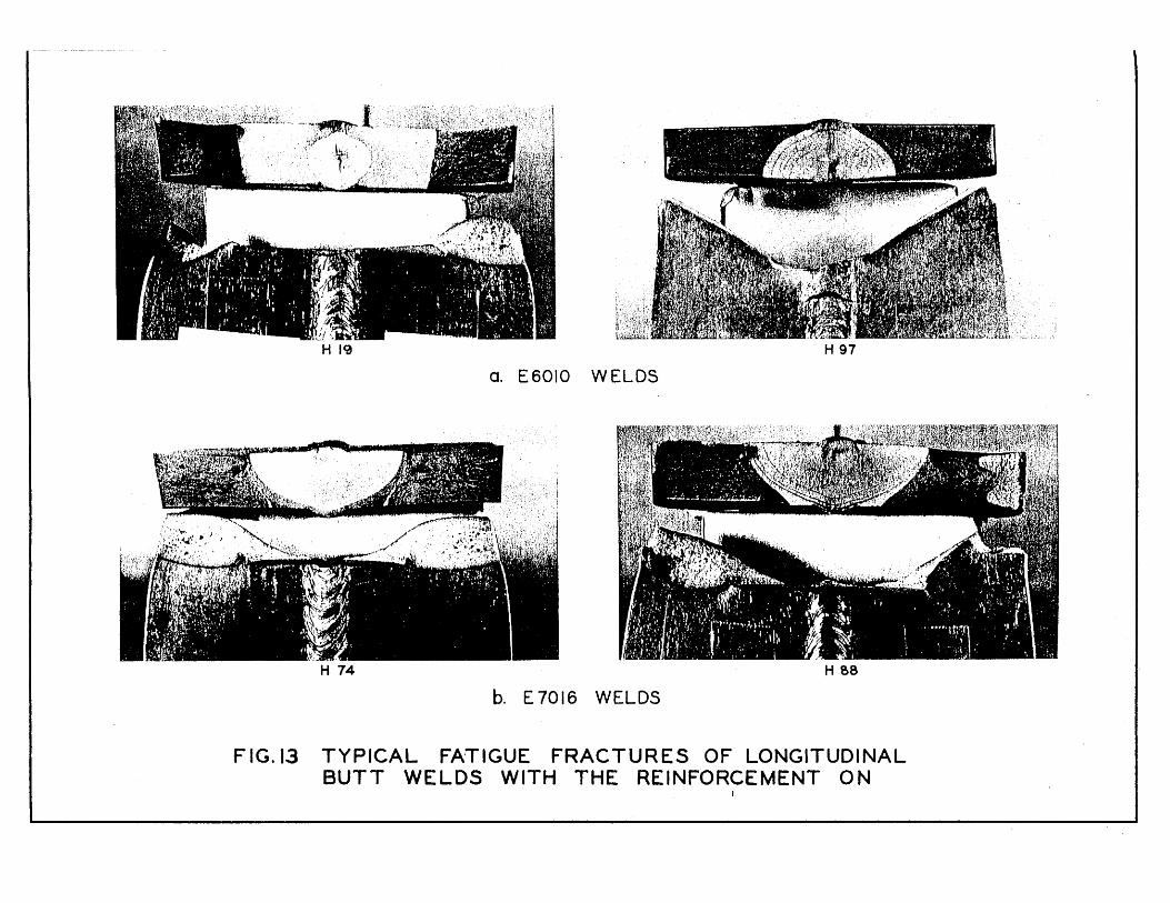
H 19 H 97
a. E6010 WELDS
H 74 H 88
b. E7016 WELDS
FIG.13 TYPICAL FA'TIGUE FRACTURES OF LONGITUDINAL BUTT WELDS WITH THE REINFORCEMENT ON ,

H 99
a. E 6010 WELDS
H 78 H 96
b. E 7016 WELDS
r1G.14 TYPICAL rATfGUE FRACTURES OF LONGITUDINAL· BUTT WELDS WITH THE REINFORCEMENT REMOVED BY GRINDING

CI)
~
60
~o
z 40
~ 30 w a: ... CI)
CI) ~
Z
20 30
60
50
40
~ 30 w 0: le/)
20 30
o MILL SCALE ON, 1953-54 • M ILL SCALE OFF, 19!>3-54
I~ 0
[] M ILL SCALE ON, 384 r-v
-- ~ O. 00 []
~ ~
[j. .... ~
\. ---------------------- --- --- -- , -.I..
50 100 500 1000 2000 5000
CYCLES TO rAILURE IN THOUSANDS
c. PLAIN PLATE TESTS
REINFORCE~ENT ON REINrORCE~ENT OFF o E6010 1953-~4 • E6010 1953-54 A E 7018 1953-54 A E 7016 1953-54 o E6010 384 G I • E6010 384 G IV V E6010 384 H III LOW TEMP. STRESS RELIEF • E 6010 384 H IV LOW TEMP. STRESS RELIEF <J E6010 384 Gil HIGH TEMP. STRESS RELIEF ~ E6010 384 GV HIGH TEMP. STRESS RELIEF I> E6010 364 G III MECHANICAL STRESS RELIEF .. E6010 384 GVI MECHANICAL STRESS RELIEF
• • .. -
50
~ t~ , ~ . ... an .- - ....... V~ •• ... .. r- .... £;<1 <l]Q
I" - - -~"
[]O I> <l •• .... . , ~ .tJ. In.n,..1 .. P'J. .... I> -~ A: ~ .. - ...
I""""LI .. []~ '" ... .. -- ---V ~ ~<l8
II--
100 500 1000 2000
C YC LES TO FAILURE IN THOUSANDS
b. LONGITUDINAL BUTT WELD TESTS
FIG.15 RESULTS OF PAST AND PRESENT FATIGUE TESTS OF LONGITUDINAL BlJTT WELDS
.&.. -
5000
---
8000
8000
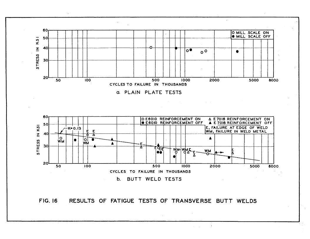
60 o MILL SCALE ON
CI) 50 • MILL SCALE Off
x: z 40 1'\ - ..
O· 00 • ~ w 30 0= t-CI)
20 50 100 500 1000 2000 5000 8000
CYCLES TO fAILURE IN THOUSANDS
O. PLAIN PLATE TESTS
60 o E6010 REINfORCEMENT ON I! E 7016 REINfORCEMENT ON
50 • E6010 REINfORCEMENT Off • E 7016 REINFORCEMENT Off CI) ~
z 40
E, fAILURE AT EDGE Of WELD WM .. FAILURE IN WELD METAL
• CI) CI) w 30 0:: l-CI)
20 ---- -- -- --
50 500 lodo 8000. 100 2000 5000
CYCLES TO fAILURE IN THOUSANDS
b. BUTT WELD TESTS
FIG. 16 RESULTS OF FATIGUE TESTS OF' TRANSVERSE BUTT WELDS

HI4 H 26
a. E 6010 WELDS
H 17 H 21
b. E 7016 WELDS
FIG.17 TYPICAL FATIGUE FRACTURES OF TRANSVERSE BUTT WELDS WITH THE REINFORCEMENT ON
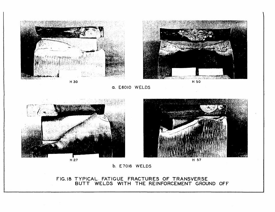
H 30 H 50
O. E6010 WELDS
H 27 H 57
b. E 7016 WELDS
FIG.18 TYPICAL· FATIGUE FRACTURES OF TRANSVERSE BUTT WELDS WITH THE REINFORCEMENT GROUND OFF
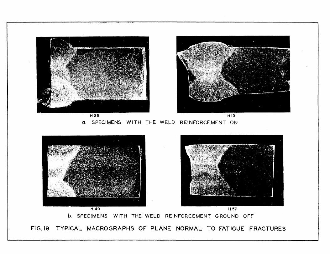
H26 HI3
a. SPECIMENS WITH THE WELD REINFORCEMENT ON
H 40 H31
b. SPECIMENS WITH THE WELD REINFORCEMENT GROUND OFF
f1G.19 TYP:ICAL MACROGRAPHS OF PLANE NORMAL TO FATIGUE FRACTURES

CI) ~
Z
Ul en w a:: .... CI)
60
50
40
30
20
15 40
0
• 1953-54 MILL SCALE ON 1953-54 MILL SCALE Off
I~ 6 M
100
II BULLETIN 327 MILl. SCALE: ON V BULLETIN 310 MILL SCALE ON
• BULLETIN 327 MILl. SCALE Off D BULLETIN 384 MILL SCALE ON
I
• • DIn.
~ O· 6 00 D
~ ..
V V ~o-r-)
-y --
500 1000 2000 5000 CYCLES TO FAILURE IN THOUSANDS
FIG.20 . RESULTS OF PAST AND P'RESENIT FATIGUE TESTS OF STEEL PLATE USED IN TRANSVERSE BUTT WELD INVESTIGATIONS
I
I
I
I
10000

60
50
U; 40 ~
z - 30 V)
~ a: t-el) 20
<J V 0
~ 40'
60
50
V) 40 ~
Z - 30 (/) (/) w a:
t; 20
1953-54 o 344-P ~ 344-05,06 • 344 -MH W = fAILURE IN WELD METAL 3.~7 -K)L A 344-55 .344-MV • 344 -NH E= fAILURE A.T EDGE OF WELD 3"~4-Z • 344-A .344-NV P= fAILURE I N PLATE
~, ~ ~P ~ E1' l~ .F ..J"V'\..J'\ ~~ WWW EP Ve: r-o
E - ~E pU} ~P ~ .... OO .... A • ~ ~ A 6.vE 0 EWW EW EW P E EW Er~~_ P
... ... ... _ ...
... -w WW EWE EWE EEEE"EP W'C.F
I __ 1_ _J~ _ __________ _ 100 500 1000 2000
CYCLES TO fAILURE IN THOUSANDS
a. SPECIMENS PREPARED WITH THE E 6010 ELECTRODE
J 0 344-XX .344-E W- FAILURE: IN WELD METAL o 344-X " 344- B E = fAILURE AT EDGE Of WELD
P = fAILURE IN PLATE
... .A ~~ WE J --wOE E www 'E~ vi ~\ • ~¥ 6 .~iv 0
WEWEW EWWW 1& a .A - -E- IF P E·P E:
----~ 15 40
'-----
100 500 1000 2000 CYCLES TO fAILURE IN THOUSANDS
b. SPECIMENS PREPARED WITH THE E6012 ELECTRODE
OPEN SYMBOLS SHOW SPECIMENS WELDED IN fLAT POSITION
5000 10000
OPEN SYMBOLS SHOW SPECIMENS WELDED IN fLAT POSITlON
-(P
-5000 10000
FIG .. 21 RES.ULTS OF PAST AND PRESENT FATIGUE TESTS OF TRANSVERSE BUTT WELDS IN THE AS-WELDED CONDITION PREPARED WITH
E6010 AND E6012 ELECTRODES.; 0- TENSION CYCLE
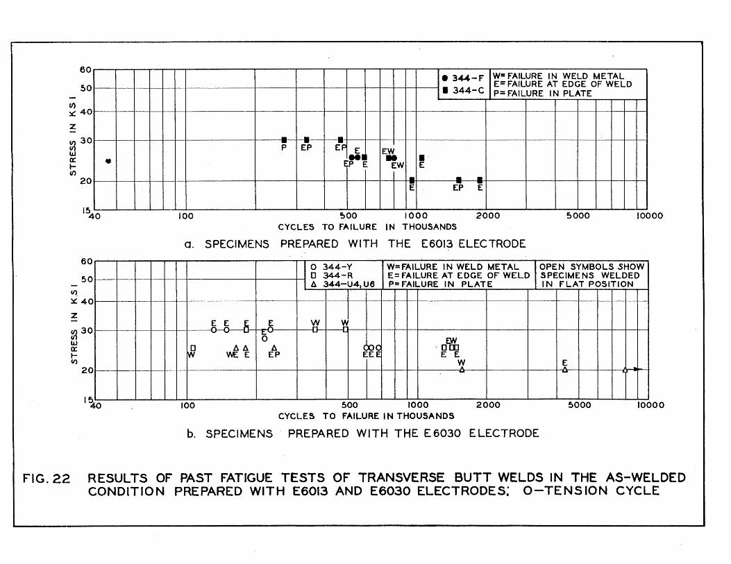
Ul
60
50
~ 40
Z
~ 30 w a: tf/)
~
20
1540
60
50
~ 40
z
~ 30 w a:: tCI)
20
I~
•
• 344-F Will FAILURE IN WELD METAL E= FAILURE AT EDGE OF WELD
• 344-C P= FAILURE I N PLATE
- - -P E-P E-P E I:'W
~~ - ." EW E
- - -E EP E
-
100 ~oo 1000 2000 5000 10000 CYCLES TO fAILURE I N THOUSANDS
o. SPECIMENS PREPARED WITH THE E6013 ELECTRODE
o 344-Y W=FAILURE IN WELD METAL OPEN SYMBOLS SHOW D 344-R E= FAILURE AT EDGE OF WELD SPECIMENS WELDED II 344-U4. U6 P= FAILURE 1 N PLAT E IN FLAT POSITION
U--+ ~ w ~ I
.... DN
r» All II ~~ , Dm WEE EP E E
Vf. ~ ..... - - .
t _________ I
100 500 1000 2000 5000 10000 CYCLES TO FAILURE I N THOUSANDS
b. SPECIMENS' PREPARED WITH THE E6030 ELECTRODE
FIG.22 RESULTS OF PAST FATIGUE TESTS OF TRA.NSVERSE BUTT WELDS IN THE AS-WELDED CONDITION PREPARED WITH E6013 AND EEi030 ELECTRODES; O-TENSION CYCLE
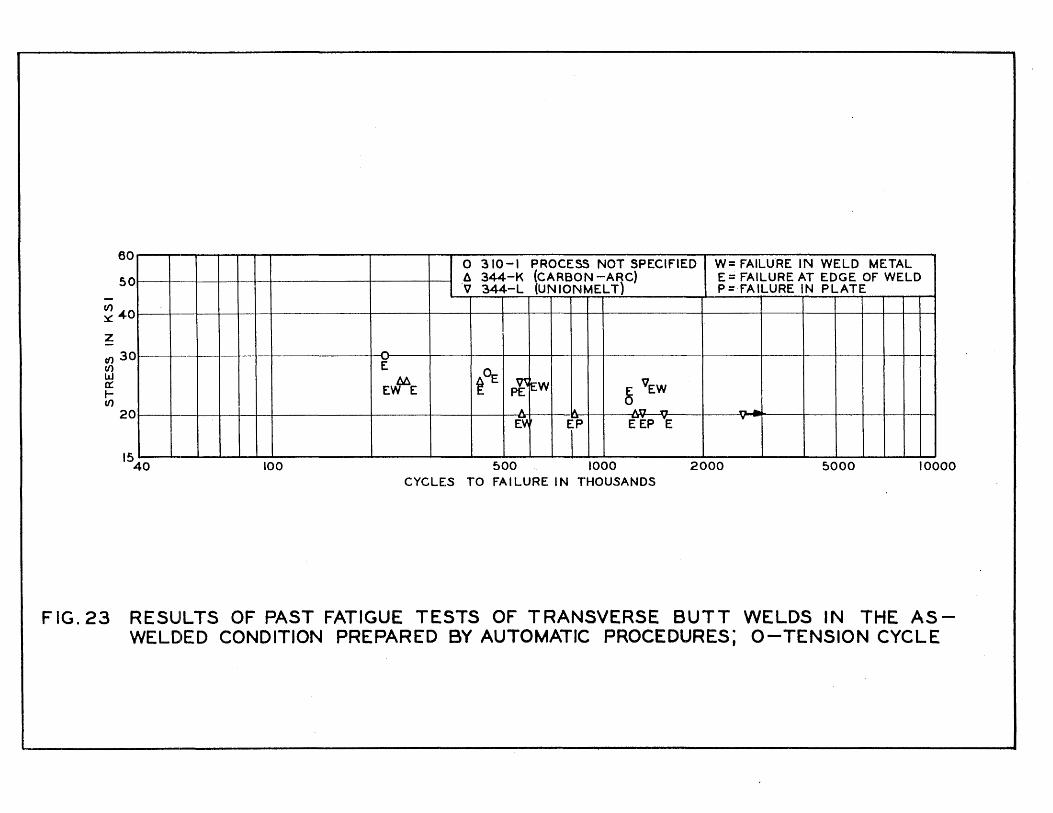
60
50
f/) ~ 40
z tf) 30 f/) w a: t-f/)
20
1540 100
o 310-1 PROCESS NOT SPECIFIED W= FAILU'RE IN WELD METAL Il 344-K (CARBON -ARC) E = FAILURE AT EDGE Of WELD 'V 344-L (UN ION MEL T) P=fAILURE IN PLATE
I
E
~~ E~E ~ EW, ~ VEW
A A An ... ........... ~ E-P EEP "E "
I 500 1000 2000 5000 10000
CYCLES TO fA I LURE I N THOUSANDS
FIG.23 RESUILTS OF PAST FATIGUE TESTS OF TRANSVERSE BUTT WELDS IN THE ASWELDED CONDITION PREPARED BY AUTOMATIC PROCEDURES; Q-TENSION CYCLE
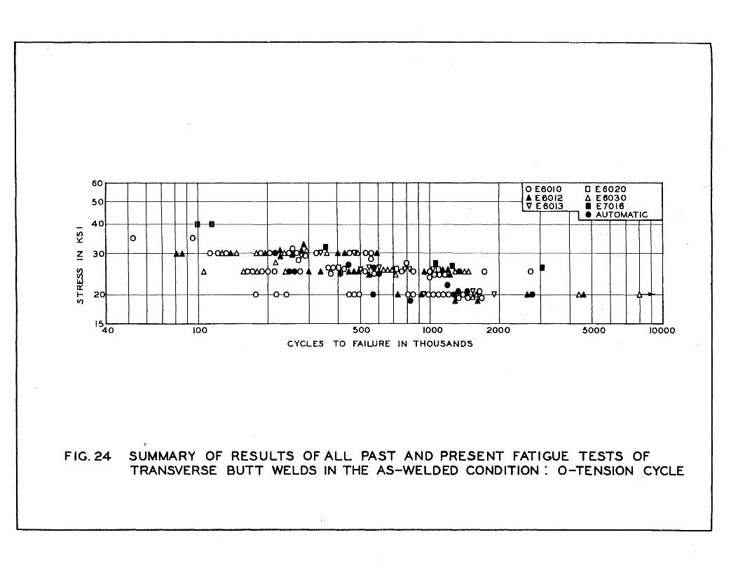
60
50
4 (/)
~
Z 3
~ a::: .- 2 V)
0
0
0
~ '-40
• •• I .. 0 0
- ..." A •
~ n. JfV)(
" ....,
100
o E6010 o E6020 • E6012 ~ E6030 V E6013 • E7016
I • AUTOMATIC
.~ n.A JI rII:R. ~ ~--I\h ... 6.~ --(JV
• A r:e ~rL. on.", ~ ~ ~O o • O~J ~ ' ....... ~ ..... <: ~-
"" ,...,...,. - ... • .A __ n~ n .I..A A .... ....,...., - - - ., ~" - ~
I
I
500 1000 2000 5000 10000
CYCLES TO fAILUR:E IN THOUSANDS
FIG.24 SUMMARY ()F RESULTS OF AL.L PAST AND PRESENT FATIGUE TESTS OF TRANSVEF~SIE BUTT WELDS IN THE ~\S-WELDED CONDITION: O-TENSION CYCLE

z
V) CIl W 0= ICIl
60
~O
20
I~O
I E= fAILURE AT EDGE or WELD P=FAILURE IN PLATE
E ~ E. A " ""E
-y
E
100
OPE N SYMBOLS SHOW o 327-IJ E6010 J 1200·F. STRESS RELIEF SPECIMENS WELDED o 310-5 HIGH TEMP. 5 TRESS RELIEF I N flAT POSITION A 310-2 HIGH TEMP. STRESS RELIEf
V 310-3 EACH BEAD PEENED
H E EP-
lr E ~b E E ........
0 E ~7 0 0 E 0
E ... E:
L...-... ___ ~ L--.-L.........-___ --
500 1000 2000 5000 10000 CYCLES TO fAILURE IN THOUSANDS
FIG.25 RESULTS OF PAST FATIGUE TESTS OF' TRANSVERSE BUTT WELDS WITH THE REINFORCEMENT ON, WELDED WITH SPECIAL 'PROCEDURES: O-TENSION CYCLE
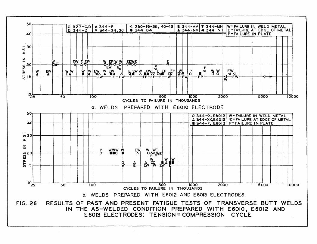
50
40
;;; 30
~
Z
CI) 20 CI) W 0::
~15
1025
50
40
(() 30 ~
z (() 20 (/} w Q:
~15
1~5
t
FIG.26
liO 327-C,D I A 344 - P . I <l 350-19-25, 40-42 1 1 344-MV I' 344-MH W=FAILURE IN WELD METAL o 344- Z V 344-54,56 • 344-04 A 344-NV ~ 344-NH E=FAILURE AT EDGE Of METAL
p. FAILURE IN PLATE
tt.E fl! ~ S;P ~~ 3; I ,
~u ~ ... y ... ~ OJ ~ ~-...
I Ef ~jr.v :I¥ I: 'WA t Ff.. l Wt 14'~1'p .t~P Jj~ b • ~ Y3rf EW ..... <l <l
.A
!
__ fYi- E-Ej-E->-EP- E >-W- E-EW-I- EP W EW ~
!
-
I
50 100 500 iOOO 2000 5000 10000 CYCLES TO FAILURE IN THOUSANDS
a. WELDS PREPARED WITH E6010 ELECTRODE
o 344-X,E6012 W- fAILURE IN WELD METAL !
A 344-XX,E 6012 E = FAILURE AT EDGE Of METAL • 344-F, E6013 P- FAILURE I N PLATE
I
~ VI. Y1. '!! Vi. Ey/' WWE ~WE -- T U E ~
W W W o ll. A T~~A!I W-E-
. fYi~E ----_ .. - ---- - -------
50 100 500 1000 2000 5000 10000 CYCLES TO FAILURE I N THOUSANDS
b. WELDS PREPARED WITH E6012 AND E6013 ELECTRODES
RESUL"rS OF PAST AND PRESENT FATIGUE TESTS OF TRANSVERSE BUTT WELDS IN THE AS-WELDED CONDITION PREPARED WITH E60tO, E60t2 AND
E6013 ELECTRODES; TENSION = COMPRESSION CYCLE
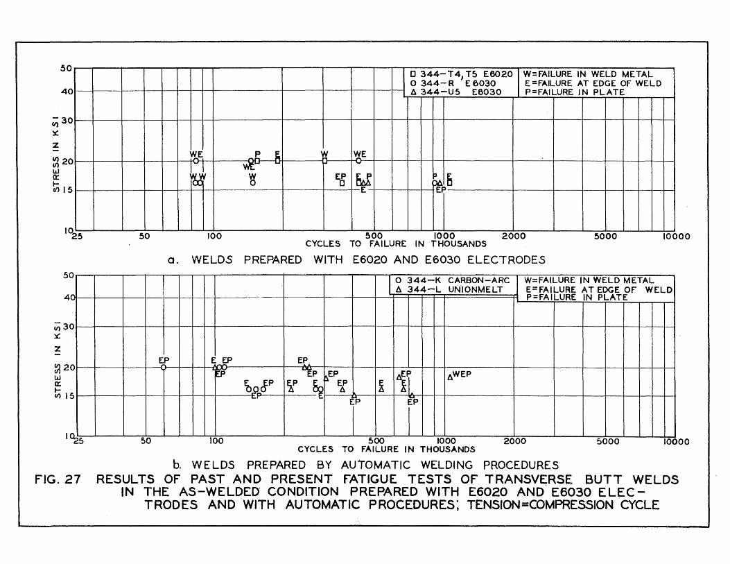
50
40
;; 30 x: z V) 20 U') w 0:: IU')15
1025
50 )
4
;;;3 ~
z
~2 w a: ICIlI
f' ....
0
0
5
I~
o 344- T 4 J T5 E6020 W= fAILURE IN WELD METAL o 344- R E 6030 E =FAfLURE AT EDGE OF WELD f!& 344-U5 E6030 P=FAILURE IN PLATE
w,..E ~ V.( WE "" wt.... ... r'"
~i 'g EP ~ ~6 0 I E EP
I
- -
50 100 500 1000 2000 5000 10000 CYCLES TO fAILURE IN THOUSANDS
a. WELDS PREPARED WITH E6020 AND E6030 ELECTRODES
I_ 0 344-K CARBON-ARC W=FAILURE IN WELD METAL A 344-L UNIONMELT E=FAILURE AT EDGE Of WELD
P=FAILURE IN PLATE
g' E.fP EP
at EP ~EP 11. f!&Wf-P i
~.9~JP if ~ EP ! f!& L..r
E"P EP
----- -
50 100 500 1000 2000 5000 10000 CYCLES TO fAILURE IN THOUSANDS
b. WELDS PREPARED BY AUTOMATIC WELDING PROCEDURES FIG.27 RESULTS OF PAST AND PRESENT fATIGUE TESTS OF TRANSV~RSE BUTT WELDS
IN THE AS-WELDED- CONDITION PREPARED WITH E6020 AND E6030 ELECTRODES AND WITH AUTOMATIC PROCEDURES: TENSION=COMPRESSJON CYCLE

50
40
C;; 30 ~
Z
(f) 20 ~ a: ~ 15
-()
1025
~.
.'-"
0
50
Q r< f:O .--. .... "~,ry'f1 "A~
0 Q( > . ~ 'P OO~
100
o E6010 o E6020 A E6012 A E6Q30 V E6013 • AUTOMATIC
...n. 1- -4l A A ,. ~ ~ --
~ .... ,
A • • 0
.. ~'Y~n: [7. r ...... .-. >J1
_ .... ..-~ ,...~ r.', M._ nI..I. J 4 >0 0 00 00 . 1-- ..... ....,
500 1000 2000 5000 10000 CYCLES TO FAILURE liN THOUSANDS
FIG.28 SUM~~ARY OF RESULTS OF ALL PAST AN[) PRESENT FATIGUE TESTS OF TRANSVERSE BUTT WELDS IN THE AS-WELDED CC)NDITION: TENSION = COMPRESSION CYCLE
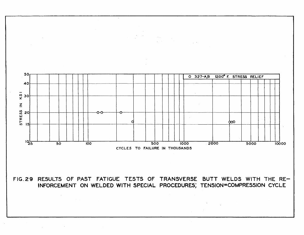
50
40
CI) 30 ~
z
CI) 20 CI)
LLJ Q:
~ 15
1Cl.Z5
-0-0
50 100
o 327-A,B 120cf f. STRESS RELIEF
....
C ~ -1---1
500 1000 2000 5000 10000 CYCLES TO FAILURE IN THOUSANDS
FIG.29 RESULTS OF PAST FATIGUE TESTS OF TRANSVERSE BUTT WELDS WITH THE REINFORCEMENT ON WELDED WITH SPECIAL PROCEDURES; TENSION=COMPRESSION CYCLE

60
50
U) ~ 40
Z
~ 30 w 0:: .... U)
U)
20
1540
60
50
~ 40
Z
U) 30 ~ " t;
20
1\0
FIG. 30
o 327-0.P E6010 • 384-fl E6010 • 1953-54 E 7016 W=fAILURE IN WELD METAL I A 327- Z £6010 , 1953-54 E6010 o 310- 7~ELECTROD£' E· FAILURE AT EDGE Of WELD V 327-X £6010 A 384-HI E6012 NO SPEClrlED) P= fAll.URE IN PLATE
'(&W b ~~'qvp ... E , ~'q ~ y ~~ W E S ~
, • iAtMt~ w-w -~~~ A ~ Q-t ..
'II . WW W- rYp
~ W -~ ,-~ ...... j~
~
~ ~ -----
100 500 . 1000 2000 5000 10000 CYCLES TO fAILURE I N THOUSANDS
a. WELDS WITHOUT PRE- OR POST-WELD SPECIAL TREATMENTS
Waf AlLURE IN WELD METAL o 3~7 -M4' A 364-F
1200·F STRE5S RELIEF I V 384-H][ E6012t "50-F STRESS RELIEF 1I00of STRESS RELIEF 0 327-U HIGH EMP. STRESS RELIEF E=FAILURE AT EDGE OF METAL
P-fAILURE IN PLATE
.~~ r-S ~ E E.
W ~ YJ"!. p
~ ref 0
~w -""'ti-" .6
! w ~yy
100 500 1000 2000 5000 CYCLES TO FAILURE IN THOUSANDS
b. WELDS WITH PRE- OR POST-WELD SPECIAL· TREATMENTS
RESULTS OF PAST AND PRESENT FATIGUE TESTS OF TRANSVERSE BUT-r WELDS WITH THE REINFORCEMENT OFF; O-TENSION CYCLE
00 00

CI)
~
z
~ IJJ 0:: r V)
5 u
~o
30 EaE ~ - -
20
15
In 25
~ P P e. e f 1
.. ..., -~ . E P • 0
.. E
50 100
o 327-G.H • 327-EJFJ l20cfF. W=FAILURE IN WELD METAL A 327-Y STRESS RELIEF E = FAILURE AT EDGE OF WELD V 344-K P = FAILURE IN PLATE
P P ~ 0 0 p
0 J_ .. -P W WT'#J rp V v---W
i
~OO 1000 2000 5000 10000 CYCLES TO FAILURE IN THOUSANDS
FIG.31 RESULTS OF PAST AND PRESENT fATIGUE TESTS OF TRANSVERSE BUTT WELDS WITH THE REINFORCEMENT OFF; TENSION = COMPRESSION CYCLE
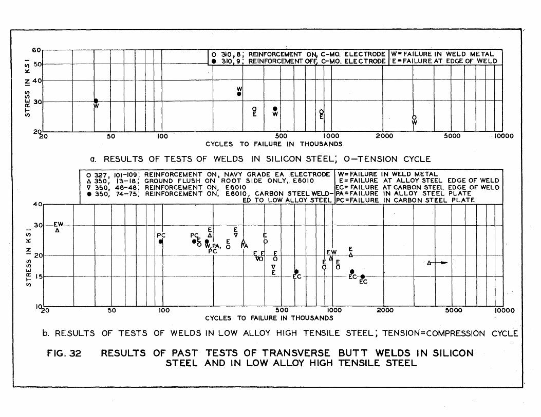
i· i/
60
CI) 50 ~
Z 40
en en W 30 0:: t-CI)
2~0
40
30 't----EW
CI)
~
Z - 20 (/') (/') w a: 15 .... CI)
I~O
A
1 0 310,8; REINFORCEMENT ON, C-MO. ELECTRODEJW- FAILURE IN WELD METAL • 310,9' REINFORCEMENT Of~ C-MO. ELECTRODE' E-FAILURE AT EDGE OF WELD
W • Ia
~ 0 • ~ E W ~ i -- --
50 100 500 1000 2000 5000 ·10000 CYCLES TO FAILURE IN THOUSANDS
a. RESULTS OF TESTS OF WELDS IN SILICON STEEL; O-TENSION CYCLE
o 327. 101-109; REINFORCEMENT ON, NAVY GRADE EAELECTROOC W= FAILURE IN WELD METAL A 350, 1~-18; GROUND FLUSH ON ROOT SIDE ONLY,. E6010 E= FAILURE AT ALLOY STEEL EDGE OF WELD V 350, 46-48; REINFORCEMENT ON, E6010 EC= FAILURE AT CARBON STEEL EDGE OF WELD • 350, 74-75; REINFORCEMENT ON. E6010, CARBON STEEL WELD- PA=FAILURE IN ALLOY STEEL PLATE
ED TO LOW ALLOY STEEL PC=FAILURE IN CARBON STEEL PLATE
E E PC PC A V E
• ·t '~tA. ~ I P 'A E E;,...J:-E EW A
\U 0 E~ -E A. --V ~ o •
LI
E I'C EC -EC
---- -- ________ ~L_. ____ ----
50 100 500 1000 2000 5000 10000 CYCLES TO FAILURE IN THOUSANDS
b. RESULTS OF TESTS OF WELDS IN LOW ALLOY HIGH TENSILE STEEL; TENSION=COMPRESSION CYCLE
FIG. 32 RESULTS OF PAS'- TESTS OF TRANSVERSE BUTT WELDS IN SILICON STEEL AND IN LOW ALLOY HIGH TENSILE STEEL