The SensiNet - Home - Wireless Sensors Networking …€¦ · · 2013-07-24The SensiNet Services...
32
Page 0 © 2011 Wireless Sensors, LLC The SensiNet Handbook
Transcript of The SensiNet - Home - Wireless Sensors Networking …€¦ · · 2013-07-24The SensiNet Services...

Page 0 © 2011 Wireless Sensors, LLC
The
SensiNet Handbook

© 2011 Wireless Sensors, LLC Page 1
Table of Contents
1. SENSINET® PRODUCT LINE .............................................................................................................................. 3
1.1 OVERVIEW .......................................................................................................................................................... 3
1.2 SERVICES GATEWAY ......................................................................................................................................... 3
1.3 MESH ROUTERS ................................................................................................................................................. 3
1.4 SMART SENSORS ............................................................................................................................................... 4
1.4.1 Ambient Temperature and Humidity Smart Sensor ..................................................................... 4
1.4.2 RTD Smart Sensor ................................................................................................................................ 4
1.4.3 4-20mA Current Smart Sensor ........................................................................................................... 4
1.4.4 0-10V Voltage Smart Sensor ............................................................................................................... 4
1.4.5 Contact Closure Smart Sensor .......................................................................................................... 4
2. SENSINET DEPLOYMENT OVERVIEW ............................................................................................................ 5
2.1 STEP 1: GATHER INSTALLATION INFORMATION ................................................................................................ 5
2.2 STEP 2: DETERMINE ENVIRONMENT TYPE ........................................................................................................ 5
2.3 STEP 3: SELECT SENSINET COMPONENTS ...................................................................................................... 5
2.4 STEP 4: DEPLOY AND COMMISSION SENSINET ................................................................................................ 5
3. VALUABLE SITE INFORMATION ...................................................................................................................... 6
3.1 AREA FLOORPLANS ........................................................................................................................................... 6
3.2 NETWORK INFORMATION ................................................................................................................................... 6
4. DETERMINING ENVIRONMENT TYPE ............................................................................................................. 7
4.1 COMMERCIAL ..................................................................................................................................................... 7
4.2 LIGHT INDUSTRIAL ............................................................................................................................................. 7
4.3 HEAVY INDUSTRIAL ............................................................................................................................................ 7

Page 2 © 2011 Wireless Sensors, LLC
5. SPECIFYING A SENSINET WIRELESS SENSOR NETWORK SOLUTION
5.1 COMMERCIAL ..................................................................................................................................................... 8
5.1.1 Breaking Installations into Multiple, Smaller Networks .............................................................. 8
5.1.2 Determine Mesh Router Requirements ........................................................................................... 9
5.2 LIGHT INDUSTRIAL AREAS ............................................................................................................................... 11
5.2.1 Breaking Installations into Multiple, Smaller Networks ............................................................ 12
5.2.2 Determine Mesh Router Requirements ......................................................................................... 13
5.3 HEAVY INDUSTRIAL AREAS ............................................................................................................................. 15
5.3.1 Breaking Installation into Multiple, Smaller Networks .............................................................. 15
5.3.2 Determine Mesh Router Requirements ......................................................................................... 16
6. DEPLOYING A SENSINET WIRELESS SENSOR NETWORK SOLUTION
6.1 COMMERCIAL ENVIRONMENTS ........................................................................................................................ 19
6.1.1 Services Gateway Placement ........................................................................................................... 19
6.1.2 Mesh Router Placement..................................................................................................................... 19
6.1.3 Sensor Placement ............................................................................................................................... 19
6.2 LIGHT INDUSTRIAL AREAS ............................................................................................................................... 20
6.2.1 Services Gateway Placement ........................................................................................................... 20
6.2.2 Mesh Router Placement..................................................................................................................... 20
6.2.3 Smart Sensor Placement ................................................................................................................... 21
6.3 HEAVY INDUSTRIAL AREAS ............................................................................................................................. 21
6.3.1 Services Gateway Placement ........................................................................................................... 21
6.3.2 Mesh Router Placement..................................................................................................................... 22
6.3.3 Smart Sensor Placement ................................................................................................................... 23
7. SENSINET SERVICES GATEWAY .................................................................................................................. 24
7.1 OVERVIEW ........................................................................................................................................................ 24
7.2 SENSINET SERVICES GATEWAY GUIDELINES FOR INSTALLATION ON IT NETWORKS ................................... 25
7.3 SENSINET SERVICES GATEWAY INTEGRATION – WEB SERVICES ................................................................. 26
7.4 WIRELESS SENSORS SERVICES GATEWAY INTEGRATION – OPC ................................................................. 26
7.5 WIRELESS SENSORS SERVICES GATEWAY INTEGRATION – ODBC .............................................................. 27
7.6 SENSINET SERVICES GATEWAY INTEGRATION – MODBUS ............................................................................ 28
7.7 SENSINET SERVICES GATEWAY INTEGRATION – HTTP ................................................................................ 29

© 2011 Wireless Sensors, LLC Page 3
Wireless Sensors, LLC
12 Old Powerhouse Rd.
Falmouth, ME 04105
www.WirelessSensors.com
888.928.4362


© 2011 Wireless Sensors, LLC Page 3
1. SensiNet® Product Line
1.1 Overview
SensiNet® is a complete wireless sensor network built for industrial and commercial environments where
high reliability is required. SensiNet includes everything you need to monitor important process and environmental data across a wide range of industries and applications.
1.2 Services Gateway
The SensiNet Services Gateway provides data access and external communication for SensiNet. SensiNet Services Gateway is a self-contained network management and access appliance that lets you securely access and analyze the data collected by Smart Sensors using a convenient browser interface. For larger installations with existing monitoring and legacy control software already in place, the SensiNet Services Gateway communicates sensor data directly to dozens of industrial automation software applications including Wonderware, LabView, RS View, OSI PI, Genesis32, CitectSCADA, Intellution, Excel and any other software compatible with ModBus, OCBC or OPC.
1.3 Mesh Routers
The SensiNet Mesh Router is an intelligent repeater that optimizes and extends the operating range of a SensiNet wireless sensor network. Every mesh router establishes direct communication links with at least two other Mesh Routers or Gateways in the network. This redundancy ensures that a wireless message coming from or going to a wireless sensor or another Mesh Router will be received.
Figure 1: SensiNet graphical deployment.

Page 4 © 2011 Wireless Sensors, LLC
1.4 Smart Sensors
Smart Sensors provide customers with the real-time process, equipment status and environmental information required for analysis and key decision making. Every Wireless Sensors Smart Sensor connects industry standard sensors to SensiNet, the most reliable wireless sensor networking technology available. Furthermore, every SensiNet Smart Sensor includes RF power amplification to deliver the maximum connection range possible—even in the harshest RF environments. Wireless Smart Sensors are available for use in the 2.4 GHz unlicensed band.
1.4.1 Ambient Temperature and Humidity Smart Sensor The SensiNet TEHU Smart Sensors are real-time temperature and humidity monitoring devices. The Smart Sensors utilize a radio amplifier and frequency diversity to ensure ultra-reliability in applications and environments that are typically unfriendly to wireless products, such as factories, refineries and power plants.
1.4.2 RTD Smart Sensor The SensiNet TEMP Smart Sensors are wireless temperature measuring devices. All of the devices operate at 2.4GHz and are FCC and CE approved. They report highly accurate and repeatable real-time temperature measurements to a central management application.
1.4.3 4-20mA Current Smart Sensor The SensiNet CURR Smart Sensors are input current monitoring devices. The CURR-1022 operates on 2.4 GHz and is an FCC and CE approved device that wirelessly transmits 4-20mA sensor data.
1.4.4 0-10V Voltage Smart Sensor The SensiNet VOLT Smart Sensors are analog input voltage monitoring devices. The devices are real-time wireless transmitters of 0-10v sensor data. The VOLT-1022 operates at 2.4 GHz and is FCC and CE approved.
1.4.5 Contact Closure Smart Sensor The CONT-1022 transmits all state changes of an attached circuit, as well as continuously transmits the current state of the circuit at a user-defined interval. When used with the SensiNet Gateway, the status is accessible via a variety of formats, including OPC, ModBus and SOAP/XML. The CONT-1022 can be used with a variety of switches including mechanical, IR and magnetic. Two contacts are supported for each CONT-1022.

© 2011 Wireless Sensors, LLC Page 5
2. SensiNet Deployment Overview This section provides a brief overview of the steps required to successfully install a SensiNet system and the details of this process are more fully described later in this document.
2.1 Step 1: Gather Installation Information
Certain customer information is useful to specify and deploy a SensiNet wireless sensor network. This includes area floor plans or schematics with locations of sensors, power and Ethernet drops.
2.2 Step 2: Determine Environment Type
Use the descriptions to determine if the environment is Commercial, Light Industrial or Heavy Industrial.
2.3 Step 3: Select SensiNet Components
Specifying a SensiNet system involves determining how many SensiNet Services Gateways, Mesh Routers and Smart Sensors you will need. Smart Sensor number and location are determined by the requirements of the application, while determining the necessary Services Gateway and Smart Sensor numbers is a two-step process. If the overall installation is very large, break the installation down into multiple, smaller networks. Then determine Mesh Router requirements for each network.
2.4 Step 4: Deploy and Commission SensiNet
SensiNet deployment involves installing the Smart Sensors, Mesh Routers and Services Gateways according to the demands of the installation and each environment type has its own unique characteristics and is described in its own section. Network commissioning is generally most effective when the Gateway is commissioned first, then the Mesh Routers and finally the Smart Sensors. This procedure allows for the network to form rapidly and in optimal fashion.

Page 6 © 2011 Wireless Sensors, LLC
3. Valuable Site Information This section describes valuable information which allows for a smooth and effective installation.
3.1 Area Floor Plans Areas within customer sites where SensiNet is deployed can be broken down into three categories based on the area construction and equipment. Each area has its own characteristics that affect SensiNet radio performance. The three areas are Commercial, Light Industrial, and Heavy Industrial and are described in Section 4. Understanding this information during the selection procedure allows proper selection of components for a trouble free deployment and extremely robust network performance.
3.2 Network Information
SensiNet has a very low IT footprint requiring only an Ethernet connection and a web browser to access all functions. The system is shipped configured to receive its IP address from a DHCP server upon connection and power up. A small ―discovery‖ application is supplied which locates the IP address it has been assigned so a browser can be ―pointed‖ to it. It is useful to know the network it is connected to so you can assure the discovery application and Gateway are located on the same network, otherwise the application cannot ―see‖ the Services Gateway. Once you have connected to the Gateway you can assign a fixed IP address if you intend to connect directly to a workstation instead of through a network. You may need a ―crossover‖ cable (depending on your computer’s Ethernet port) and will need to make sure you know the IP address, network ID and subnet mask for the workstation. If not familiar with these network concepts your IT department should be able to help. No other network services are required.

© 2011 Wireless Sensors, LLC Page 7
4. Determining Environment Type Wireless Sensors defines three environments: Commercial, Light Industrial and Heavy Industrial, where SensiNet systems are typically deployed. Each environment has unique properties that affect how SensiNet is specified and deployed.
4.1 Commercial
Commercial environments are typically constructed of drywall and studs and are found in most office buildings. Small-item manufacturing can be conducted in commercial areas but does not utilize large equipment that might interfere with transmission paths. Examples of commercial environments are office buildings, hospitals, pharmaceutical labs and data centers.
Figure 2: Commercial environment picture and layout
4.2 Light Industrial
Light industrial environments typically have manufacturing facilities utilizing metal equipment. The building construction might be drywall and stud or it could be metal and concrete. The metal equipment used is typically smaller than that found in heavy industrial environments and might consist of large machines in several rooms or a machine line that is 5 to 20 feet tall and housed in one large room. Transmission paths are often blocked by this equipment. Examples of light industrial environments are biotech manufacturing and injection molding operations.
Figure 3: Light Industrial interior pictures
4.3 Heavy Industrial
Heavy industrial environments are categorized by very large, metal equipment in an open-air environment or in buildings that are several stories tall. The metal equipment used will be much larger and taller than that used in light industrial environments. Examples of heavy industrial environments are refineries, power plants and steel mills.
Figure 4: Heavy Industrial exterior and interior pictures
Page 8 © 2011 Wireless Sensors, LLC
5. Specifying a SensiNet Wireless Sensor Network Solution
While the application dictates the number and type of Smart Sensors to be installed, the environment determines the number of SensiNet Services Gateways, and Mesh Routers required in the particular environment whether Commercial, Light Industrial, or Heavy Industrial. Each environment has unique properties that result in various specification procedures.
5.1 Commercial
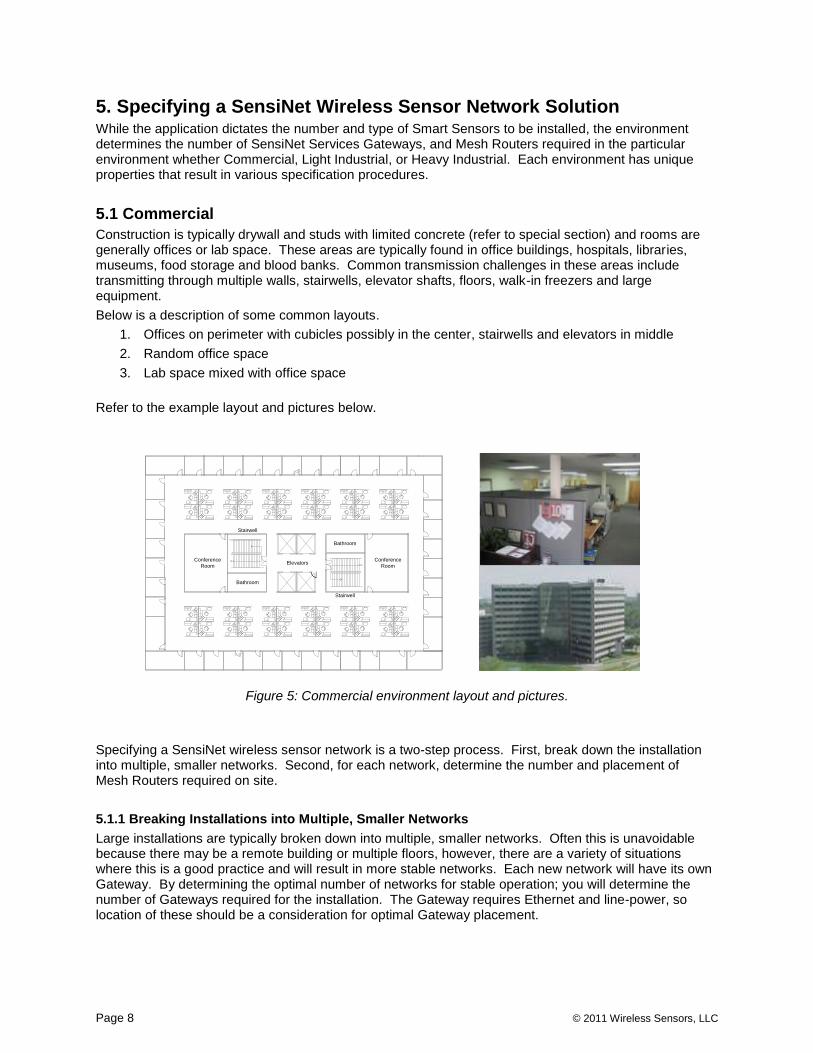
Construction is typically drywall and studs with limited concrete (refer to special section) and rooms are generally offices or lab space. These areas are typically found in office buildings, hospitals, libraries, museums, food storage and blood banks. Common transmission challenges in these areas include transmitting through multiple walls, stairwells, elevator shafts, floors, walk-in freezers and large equipment.
Below is a description of some common layouts.
1. Offices on perimeter with cubicles possibly in the center, stairwells and elevators in middle
2. Random office space
3. Lab space mixed with office space
Refer to the example layout and pictures below.
Up
Stairwell
ElevatorsConference
Room
Bathroom
Up
Stairwell
Bathroom
Conference
Room
2'-6"
2'-6"
Figure 5: Commercial environment layout and pictures.
Specifying a SensiNet wireless sensor network is a two-step process. First, break down the installation into multiple, smaller networks. Second, for each network, determine the number and placement of Mesh Routers required on site.
5.1.1 Breaking Installations into Multiple, Smaller Networks
Large installations are typically broken down into multiple, smaller networks. Often this is unavoidable because there may be a remote building or multiple floors, however, there are a variety of situations where this is a good practice and will result in more stable networks. Each new network will have its own Gateway. By determining the optimal number of networks for stable operation; you will determine the number of Gateways required for the installation. The Gateway requires Ethernet and line-power, so location of these should be a consideration for optimal Gateway placement.

© 2011 Wireless Sensors, LLC Page 9
This section gives examples to each of the rules for breaking down networks that are listed below.
Figure 6: Rules for breaking installations into multiple, smaller networks.
Once the installation is broken down into smaller, manageable networks, you must now determine the required number of Mesh Routers and location.
5.1.2 Determine Mesh Router Requirements
Mesh Router specification guidelines and the Mesh RangeFinder table are described below. Use these two tools to determine the optimal number and placement of Mesh Routers.
Mesh Router Placement Guidelines
Follow these guidelines when deciding Mesh Router placement.
1. Place Mesh Router roughly halfway between a Smart Sensor or a cluster of Smart Sensors.
2. Maximize use of open space such as hallways.
3. Minimize number of walls and other obstacles transmitting through.
4. When using multiple Mesh Routers to connect to a Smart Sensor, place Mesh Routers equal distance apart from the Smart Sensors.
Rule 1: Each separate building will require a separate network.
Building 1Network 1
Building 2Network 1
Rule 1
Rule 2:
No more than two floors should be combined in a network and only one if floors contain metal pans.
Rule 3: Create two or more networks when transmitting across dynamic, high-movement environments such as roads, warehouses or shipping yards.
SensiNet Gateway
Network 1warehouse 1
SensiNet Gateway
Rule 4: Enclosed concrete areas will require their own network.
SensiNet Gateway
Con
cre
te
SensiNet Gateway
Rule 5: Remote clusters of nodes require their own network.
SensiN et Gateway
SensiN et Gateway
Rule 2

Page 10 © 2011 Wireless Sensors, LLC
Mesh RangeFinder
The Mesh RangeFinder allows you to calculate the maximum range to expect in each point to point connection. While it is optimal to place a Mesh Router halfway between a Smart Sensor or a cluster of Smart Sensors, if the halfway distance is greater than what is calculated by the RangeFinder, then extra Mesh Routers may be required. The Mesh RangeFinder table is shown below.
Commercial Areas = 200’ Base
Wall Type 0-10’ 50’ 100’
Drywall 25’ 50’ 50’
Concrete 50’ 100’ n/a
Figure 7: Mesh RangeFinder
For every wall the signal passes through, subtract the corresponding distance from the baseline distance to determine the maximum recommended range for the Mesh Router.
Example #1: Open air (no obstacles)
When there are no obstacles to be transmitted through, there is no need to reduce the base range, thus the maximum recommended range between routers is 200’. Figure 8 below shows this graphically.
Figure 8: Maximum recommended range for open air transmission.
Example #2: One wall 10’ away
Subtract 25’ from the base range to get a maximum recommended range of 175’ (200’ – 25’ = 175’). See Figure 9 below.
Figure 9: Recommended transmission range for obstacle 10’ from transmitter.
Open Space 200’
165' after wall 10’
175’ total transmission length

© 2011 Wireless Sensors, LLC Page 11
Example #3: One wall 50’ away
Subtract 50’ from the base range for a maximum recommended range of 150’ (200’ – 50’ = 150’). See Figure 10 below.
Figure 10: Recommended transmission range for obstacle 50’ from transmitter.
Example #4: Two walls: one wall 10’ away and a second wall 50’ away. Subtract 25’ because of the wall 10’ away then subtract an additional 50’ because of the wall 50’ away (200’ – 25’ – 50’ = 125’). See Figure 11 below.
Figure 11: Transmitting through two walls.
5.2 Light Industrial Areas
Light industrial construction is defined the same as Commercial construction (i.e. drywall and stud) but also has a large amount of equipment in the rooms. Food manufacturing, pharmaceutical manufacturing, biotech, semiconductor and blood banks are common industries housed in light industrial environments. Common transmission challenges in this environment are large equipment, transmitting through several drywall walls, transmitting through concrete and through floors.
Refer to the pictures below.
Figure 12: Light Industrial environments
l
10' 50' 125’ Max Range
65’ of range after wall
100’ 50’
150’ Max Range

Page 12 © 2011 Wireless Sensors, LLC
Specifying a SensiNet wireless sensor network is a two-step process. First, break down the installation into multiple, smaller networks. Second, for each network, determine the number and placement of Mesh Routers required onsite.
5.2.1 Breaking Installations into Multiple, Smaller Networks
Large installations are typically broken down into multiple, smaller networks. Often this is unavoidable because there may be a remote building or multiple floors, however, there are a variety of situations where this is a good practice and will result in more stable networks. Each new network will have its own Gateway. By determining the optimal number of networks for stable operation; you will determine the number of Gateways required for the installation. The Gateway requires Ethernet and line-power, so location of these should be a consideration for optimal Gateway placement.
This section gives examples to each of the rules for breaking down networks that are listed below.
Figure 13: Rules for breaking installations into multiple, smaller networks.
Once the installation is broken down into smaller, manageable networks, you must now determine Mesh Router number and location.
Rule 1: Each separate building will require a separate network.
Building 1Network 1
Building 2Network 1
Rule 1
Rule 2: No more than two floors should be combined in a network and only one if floors contain metal pans.
SensiNet Gateway
SensiNet Gateway
Rule 2
Rule 3: Create two or more networks when transmitting across dynamic, high-movement environments such as roads, warehouses or shipping yards.
SensiNet Gateway
Network 1warehouse 1
SensiNet Gateway
Rule 4: Enclosed concrete areas will require their own network.
SensiNet Gateway
Con
cre
te
SensiNet Gateway
Rule 5: Remote clusters of nodes require their own network.

© 2011 Wireless Sensors, LLC Page 13
5.2.2 Determine Mesh Router Requirements
Mesh Router specification guidelines and the Mesh RangeFinder table are described below. Use these two tools to determine the optimal number and placement of Mesh Routers.
Mesh Router Placement Guidelines
Follow these guidelines when deciding Mesh Router placement.
1. Place Mesh Router roughly halfway between Smart Sensor or a cluster of Smart Sensors.
2. Maximize use of open space such as hallways.
3. Minimize number of walls and other obstacles transmitting through.
4. When using multiple Mesh Routers to connect to a Smart Sensor, place Mesh Routers equal distance apart.
Mesh Range Finder
The Mesh RangeFinder allows you to calculate the maximum range to expect in each point-to-point connection. It is optimal to place Mesh Routers halfway between a Smart Sensor or cluster of Smart Sensors. However, if the halfway distance is greater than the distance calculated by the RangeFinder, then extra Mesh Routers will be required.
Light Industrial Areas = 250’ Base
Material Type 0-10’ 50’ 100’ 150’
Drywall 75’ 100’ 100’ 90
Concrete 150’ 175’ n/a n/a
Metal 150’ 175’ n/a n/a
Figure 14: RangeFinder for Light Industrial Areas
For every wall the signal passes through, subtract the corresponding distance from the baseline distance to determine the maximum recommended range for the Mesh Router.
Example #1: Open air (no obstacles)
When there are no obstacles that are transmitted through, there is no need to reduce the base range, thus the maximum recommended range between routers is 250’. Figure 15 below shows this graphically.
Figure 15: Maximum recommended range for open air transmission.
Open Space
250’

Page 14 © 2011 Wireless Sensors, LLC
Example #2: One concrete wall 10’ away
Subtract 150’ from the base range to get a maximum recommended range of 100’ (250’ – 150’ = 100’). See Figure 16 below.
Figure 16: Recommended transmission range for obstacle 10’ from transmitter.
Example #3: One concrete wall 50’ away
Subtract 175’ from the base range for a maximum recommended range of 75’ (250’ – 175’ = 75’).
See Figure 17 below.
Figure 17: Recommended transmission range for obstacle 50’ from transmitter.
Example #4: Two drywall walls: one wall 10’ away and a second wall 50’ away. Subtract 25’ because of the wall 10’ away then subtract an additional 50’ because of the wall 50’ away (200’ – 25’ – 50’ = 125’). See Figure 18 below.
Figure 18: Transmitting through two walls.
r l
10' 50' 125’ Max Range
65’ of range after wall
90’ after wall
10’
100’ total transmission length
25' 50’ r
75’ Max Range

© 2011 Wireless Sensors, LLC Page 15
5.3 Heavy Industrial Areas
The construction in Heavy Industrial environments consists of very large metal equipment typically found in open-air plants or housed in very large buildings. Concrete is usually very abundant in the walls, floors and equipment. Oil and gas refineries, steel mills, power plants, aluminum plants and nuclear plants are typically classified as heavy industrial. Common transmission challenges in these areas include transmission through concrete and around very large metal equipment. Refer to the layouts below.
Figure 19: Pictures of Heavy Industrial environments.
Specifying a SensiNet wireless sensor network is a two-step process. First, break down the installation into multiple, smaller networks. Second, for each network, determine the number and placement of Mesh Routers required on site.
5.3.1 Breaking Installation into Multiple, Smaller Networks
Large installations are typically broken down into multiple, smaller networks. Often this is unavoidable because there may be remote buildings or multiple floors, however, there are a variety of situations where this is a good practice and will result in more stable networks. Each new network will have its own Gateway. By determining the optimal number of networks for stable operation; you will determine the number of Gateways required for the installation. The Gateway requires Ethernet and line-power, so location of these should be a consideration for optimal Gateway placement.

Page 16 © 2011 Wireless Sensors, LLC
This section gives examples to each of the rules for breaking down networks that are listed below.
Figure 20: Rules for breaking installations into multiple, smaller networks.
Once the installation is broken down into smaller, manageable networks, you must now determine Mesh Router number and location.
5.3.2 Determine Mesh Router Requirements
Mesh Router specification guidelines and the Mesh RangeFinder table are described below. Use these two tools to determine the optimal number and placement of Mesh Routers.
Mesh Router Placement Guidelines
Follow these guidelines when deciding Mesh Router placement.
1. Place Mesh Router roughly halfway between Smart Sensor or a cluster of Smart Sensors.
2. Maximize use of open space such as hallways.
3. Minimize number of walls and other obstacles transmitting through.
4. When using multiple Mesh Routers to connect to a Smart Sensor, place Mesh Routers equal distance apart.
Rule 1: Each separate building will require a separate network.
Building 1Network 1
Building 2Network 1
Rule 1
Rule 2: No more than two floors should be combined in a network and only one if floors contain metal pans.
SensiNet Gateway
SensiNet Gateway
Rule 2
Rule 3: Create two or more networks when transmitting across dynamic, high-movement environments such as roads, warehouses or shipping yards.
SensiNet Gateway
Network 1warehouse 1
SensiNet Gateway
Rule 4: Enclosed concrete areas will require their own network.
SensiNet Gateway
Con
cre
te
SensiNet Gateway
Rule 5: Remote clusters of nodes require their own network.

© 2011 Wireless Sensors, LLC Page 17
Mesh Range Finder
The Mesh RangeFinder allows you to calculate the maximum range to expect in each point-point connection. While it is optimal to place Mesh Routers halfway between a Smart Sensor or a cluster of Smart Sensors. If the halfway distance is greater than what is calculated by the RangeFinder then extra Mesh Routers will be required.
Heavy Industrial Areas = 300’ Base
Obstacle Type 0-10’ 50’ 100’
Concrete 200’ 225’ n/a
Metal 200’ 225’ n/a
Figure 21: RangeFinder for Heavy Industrial environments
A general idea to keep in mind when working in a Heavy Industrial area is that the SensiNet transmitters will transmit either near their base range (300’) or a much shorter range (i.e. 100’ or less). This is because the obstacles in Heavy Industrial areas.
Example #1: Open air (no obstacles)
When there are no obstacles that to be transmitted through, there is no need to reduce the base range, thus the maximum recommended range between routers is 300’. Figure 22 below shows this graphically.
Figure 22: Maximum recommended range for open air transmission.
Open Space
300’

Page 18 © 2011 Wireless Sensors, LLC
Example #2: One concrete wall 10’ away
Subtract 200’ from the base range to get a maximum recommended range of 100’ (300’ – 200’ = 100’). See Figure 23 below.
Figure 23: Recommended transmission range for obstacle 10’ from transmitter.
Example #3: One concrete wall 50’ away
Subtract 250’ from the base range for a maximum recommended range of 100’ (300’ – 200’ = 100’).
See Figure 24 below.
Figure 24: Recommended transmission range for obstacle 50’ from transmitter.
50' 50’ r
100’ Max Range
90’ after wall
10’
100’ total transmission length

© 2011 Wireless Sensors, LLC Page 19
6. Deploying a SensiNet Wireless Sensor Network Solution
This section describes the various deployment best practices for Commercial, Light Industrial and Heavy Industrial environments.
6.1 Commercial Environments
SensiNet wireless sensor networks are best deployed in the following order: Services Gateway, Mesh Routers, then Smart Sensors.
6.1.1 Services Gateway Placement
Use the following guidelines to determine Services Gateway placement.
1. Place in or near a cluster of data points.
2. Place near Ethernet drop and line power or run these to the Gateway.
3. Place high, near the ceiling similar to the sensor placement described above.
4. For areas with several large obstacles in the center such as high-rise office buildings, place at far end then use Mesh Routers to communicate to either side of obstacles.
6.1.2 Mesh Router Placement
Use the following guidelines to determine Mesh Router placement.
1. Lengthen transmission distances from transmitters in open space and shorten when transmitting through thick walls or concrete.
2. Make use of open space by placing high above equipment and transmitting down hallways, corridors and above machine lines.
3. Place in line of sight to Gateway, other Mesh Routers and Smart Sensors whenever possible.
4. Minimize the number of walls the signal transmits through.
5. Place near line power or run it to the Mesh Router.
6.1.3 Sensor Placement
Below are best practices guidelines for deploying a stable SensiNet Wireless Sensor Network. SensiNet is typically deployed in the following order: Gateway, Mesh Routers then Smart Sensors.
Customers determine general area for sensor placement. Use the following guidelines for final placement.
1. Place toward inside of building near center of network rather than near outer walls.
2. Place high near the ceiling. Install on walls, set on top equipment or even above ceiling tiles. The majority of equipment and material is on the floor and roughly 6-8’ tall leaving the top few feet clear for transmission.
Figure 26: Example of Smart Sensor deployed in Commercial environment.

Page 20 © 2011 Wireless Sensors, LLC
6.2 Light Industrial Areas
SensiNet wireless sensor networks are best deployed in the following order: Services Gateway, Mesh Routers then Smart Sensors.
6.2.1 Services Gateway Placement
Use the following guidelines to determine Services Gateway placement.
1. Place in or near a cluster of data points
2. Place near Ethernet drop and line power or run these to the Gateway.
3. Place high near the ceiling similar to the sensor placement described above.
4. For areas with several large obstacles in the center such as high-rise office buildings, place at far end then use Mesh Routers to communicate to either side of obstacles.
6.2.2 Mesh Router Placement
Use the following guidelines to determine Mesh Router placement.
1. Lengthen transmission distances from transmitters in open space and shorten when transmitting through thick walls or concrete.
2. Make use of open space by placing high above equipment and transmitting down hallways, corridors and above machine lines.
3. Place in line of sight to Gateway, other Mesh Routers and Smart Sensors whenever possible.
4. Minimize the number of walls the signal transmits through.
5. Place near line power or run it to the Mesh Router.
6. Avoid mounting on steel columns or beams.
Figure 27: Example of Mesh Router placement in Light Industrial environment.

© 2011 Wireless Sensors, LLC Page 21
6.2.3 Smart Sensor Placement
1. Make use of open space by placing Smart Sensors high above equipment and transmitting down hallways, corridors and above machine lines.
2. Place in line of sight of the Gateway and Mesh Routers whenever possible
3. Minimize number of walls the signal transmits through
4. Lengthen distance from Mesh or Gateway in open space and shorten when transmitting through concrete.
Figure 28: Example of Smart Sensor deployed in a Heavy Industrial environment.
6.3 Heavy Industrial Areas
Below are best practices guidelines for deploying a stable SensiNet wireless sensor network. SensiNet is typically deployed in the following order: Smart Sensors, Gateway then Mesh. Customers determine general area for Smart Sensor placement. Use the following guidelines for final placement.
6.3.1 Services Gateway Placement
Use the following guidelines to determine Services Gateway placement.
1. Place in or near a cluster of data points
2. Place near Ethernet drop and line power or run these to the Gateway.
3. Place high near the ceiling similar to the Smart Sensor placement described in Figure 29.
4. For areas with several large obstacles in the center such as high-rise office buildings, place at far end then use Mesh Routers to communicate to either side of obstacles.

Page 22 © 2011 Wireless Sensors, LLC
6.3.2 Mesh Router Placement
Use the following guidelines to determine Mesh Router placement.
1. Lengthen transmission distances from transmitters in open space and shorten when transmitting through thick walls or concrete.
2. Make use of open space by placing high above equipment and transmitting down hallways, corridors and above machine lines.
3. Place in line of sight to Gateway, other Mesh Routers and Smart Sensors when possible.
4. Minimize the number of walls the signal transmits through.
5. Place near line power or run it to the Mesh Router.
6. Avoid mounting on steel columns or beams.
Figure 29: Example of Mesh Router deployed in a Heavy Industrial environment.

© 2011 Wireless Sensors, LLC Page 23
6.3.3 Smart Sensor Placement
Below are best practices guidelines for deploying a stable SensiNet wireless sensor network in Heavy Industrial environments. SensiNet is typically deployed in the following order: Smart Sensors, Gateway, then Mesh Router. Customers determine general area for Smart Sensor placement. Use the following guidelines for final placement.
1. Place toward inside of building near Mesh rather than near outer walls.
2. Place high near the ceiling. Install on walls, set on top equipment or even above ceiling tiles. The majority of equipment and material is on the floor and roughly 6-8’ tall leaving the top few feet clear for transmission.
Figure 30: Example of Smart Sensor deployed in a Heavy Industrial environment.

Page 24 © 2011 Wireless Sensors, LLC
7. SensiNet Services Gateway
This section contains information about the SensiNet Services Gateway.
7.1 Overview The SensiNet Services Gateway provides data access and external communications for the SensiNet wireless sensor network. A self-contained network management and access appliance, SensiNet’s Services Gateway lets you securely access and analyze the data collected by Smart Sensors using a convenient browser interface. The Gateway provides SensiNet Network configuration tools and allows three methods for viewing data:
1. Third Party Software Integration 2. Standalone HMI 3. SensiNet Services Site
OPC, ODBC, ModBus Built In Application SensiNet Services Site
Figure 31: Wireless Sensors Services Gateway capabilities and protocols Third Party Software Integration For larger installations with existing monitoring and legacy control software already in place, the SensiNet Gateway communicates sensor data directly to dozens of industrial automation software applications including:
Wonderware
ICONICS
Intellution
Citect
LabView
Other ModBus, ODBC, and OPC-compatible software Standalone HMI The SensiNet Gateway provides standalone HMI capability including the following functions:
Graphical and tabular real-time and historical data
Alarms

© 2011 Wireless Sensors, LLC Page 25
SensiNet Services Site The Services Gateway can integrate with the SensiNet Services Site.
1. View sensor data from any web browser in any location 2. Graphical and tabular real-time and historical data 3. Alarms
7.2 SensiNet Services Gateway Guidelines for Installation on IT Networks
The SensiNet Services Gateway provides data access and external communications for the SensiNet wireless sensor network. Gateway usage guidelines are provided below. OPC, ODBC, ModBus Built In Applications SensiNet Services Site
Figure 32: Wireless Sensors Services Gateway capabilities and protocols
Best Practices Wireless Sensors recommends the steps outlined below in order to make the best use of your Gateway:
1. Configure access control to the Gateway by navigating to Configuration->User Access. It is recommended that administrative privileges are only given to the appropriate users.
2. Power your Gateway through an uninterruptible power supply.

Page 26 © 2011 Wireless Sensors, LLC
7.3 SensiNet Services Gateway Integration – Web Services The SensiNet Services Gateway is easily configurable to use web services to transmit data. This allows for designing web applications to make use of the sensor data aggregated by the Gateway. To manage the OPC data access on the Gateway, navigate to Configuration -> Data Connections -> Web Services. This will produce the screen in Figure 33.
Figure 33: Gateway web services configuration screen The basic steps for configuring Web Services are:
1. Activate the service by selecting ―Active‖ in the pull-down menu
7.4 Wireless Sensors Services Gateway Integration – OPC The SensiNet Services Gateway is easily configurable to communicate via OPC. The SensiNet OPC server software can aggregate data from any or all Gateways on the subnet and provides OPC data services to third-party software. The basic steps for configuring OPC are
1. Install and configure SensiNet OPC server SW on host PC 2. Configure Gateway to add an ODBC host connection for server PC 3. Configure SensiNet OPC server SW 4. Map OPC tags to variables in third-party software
When finished changing information, click Save Changes to save the information.

© 2011 Wireless Sensors, LLC Page 27
7.5 Wireless Sensors Services Gateway Integration – ODBC The Wireless Sensors Gateway is easily configurable to communicate via ODBC. This allows multiple third-party applications access to the data on the Gateway. To manage the OPC data access on the Gateway, navigate to Configuration -> Data Connections -> ODBC. This will produce the screen in Figure 34.
Figure 34: Gateway ODBC configuration screen
The basic steps for configuring ODBC are: 1. Enter the Classless Inter-Domain Routing (CIDR) Address of the client machine or network. For
example, the CIDR address for a single host might be 192.168.185.76/32 and for a network 192.168.185.0/24.
2. Leave the other fields with the default values and click ―Add‖

Page 28 © 2011 Wireless Sensors, LLC
7.6 SensiNet Services Gateway Integration – ModBus The SensiNet Services Gateway is easily configurable to communicate via ModBus TCP/IP to external devices. The Gateway acts as a ModBus slave to make data available to ModBus master devices. In the Gateway Interface, SensiNet Smart Sensor devices ports can be mapped to ModBus registers. To manage the ModBus slave feature on the Gateway, navigate to Configuration -> Data Connections -> ModBus. This will produce the screen in Figure 35.
Figure 35: Gateway ModBus configuration screen Within the ModBus Configuration page you can set several options:
1. Set ModBus slave option as Active or Inactive by clicking the appropriate radio button. 2. Set Gateway ModBus slave ID by typing the ID into the appropriate field. 3. Change ModBus register mapping by entering new information into the appropriate fields.
When finished changing information, click Save Changes to save the information.

© 2011 Wireless Sensors, LLC Page 29
7.7 SensiNet Services Gateway Integration – HTTP The SensiNet Services Gateway is easily configurable to transmit via HTTP. This allows you to transmit sensor data to an Application Service Provider site. To manage the OPC data access on the Gateway, navigate to Configuration -> Data Connections -> HTTP. This will produce the screen in Figure 36.
Figure 36: Gateway HTTP Transmission configuration screen
The basic steps for configuring HTTP are: 1. Activate the service by selecting the ―Active‖ Radio Button. 2. Enter the destination URL to transmit data to. 3. Enter the password required for the site data is being transmitted to. 4. Specify the time between updates in minutes.


![Eclipse IoT stack with Java and the End-to-end IoT solutions...End-to-end IoT? Actuators/Sensors + Gateway + [ Cloud ] + User front-end 1. Sensors/Actuators Sense the physical environment](https://static.fdocuments.in/doc/165x107/5f9f73d4a6911045bd00df1b/eclipse-iot-stack-with-java-and-the-end-to-end-iot-solutions-end-to-end-iot.jpg)