SureCross DX80 Gateway for Wireless Q45...
12
SureCross DX80 Gateway for Wireless Q45 Sensors Configurable DX80 Gateway that uses DIP switches to map inputs from up to six Nodes (or Wireless Q45 Sensors) to the Gateway's outputs The SureCross® wireless system is a radio frequency network with integrated I/O that operates in most environments and eliminates the need for wiring runs. Systems are built around a Gateway, which acts as the wireless network master device, and one or more Wireless Q45 Sensors. • Wireless industrial I/O device with six discrete (sourcing) inputs and six discrete (sourcing) out- puts • DIP switches allow the user to select one of eight defined I/O mapping configurations to automat- ically map the Nodes' inputs to this Gateway's outputs • 10 to 30V dc power input • Frequency Hopping Spread Spectrum (FHSS) technology and Time Division Multiple Access (TDMA) control architecture ensure reliable data delivery within the unlicensed Industrial, Scien- tific, and Medical (ISM) band • Transceivers provide bidirectional communication between the Gateway and Node, including fully acknowledged data transmission • Site Survey analyzes the network’s signal strength and reliability and displays the results on the Gateway's LCD • LCD shows I/O status, Site Survey results, and network status information • Lost RF links are detected and relevant outputs set to user-defined conditions For additional information, updated documentation, and accessories, refer to Banner Engineering's website, www.bannerengineer- ing.com/surecross. Model Frequency Environmental Rating I/O DX80G2M6-Q-KR 2.4 GHz ISM Band IP67, NEMA 6 Inputs: Six sourcing discrete Outputs: Six sourcing discrete WARNING: Not To Be Used for Personnel Protection Never use this device as a sensing device for personnel protection. Doing so could lead to serious injury or death. This device does not include the self-checking redundant circuitry necessary to allow its use in personnel safety applications. A sensor failure or malfunction can cause either an energized or de- energized sensor output condition. The SureCross® Wireless Q45 Sensor Network The SureCross® DX80 wireless I/O network provides reliable monitoring without the burden of wiring or conduit installation. The SureCross wireless network can operate independently or in con- junction with a Modbus host system, PLC, and/or PC software. The SureCross DX80 network is a deterministic system—the net- work identifies when the radio signal is lost and drives relevant out- puts to user-defined conditions. Once the radio signal is reac- quired, the network returns to normal operation. Each wireless network system consists of one Gateway and one or more Wireless Q45 Sensors. A Gateway acts as the master device within each radio network, initiates communication and reporting with the Nodes, and controls the timing for the entire network. The Gateway also holds the configuration for the network. Every wireless network must have one Gateway that schedules communication traffic and controls the I/O configuration for the network. A radio network contains only one Gateway, but may contain many Wireless Q45 Sensors. Similar to how a gateway device on a wired network acts as a “portal” between networks, the SureCross Gateway acts as the portal between the wireless network and the host controller. P/N 182818 10/2013 0 161862 0
-
Upload
truongkien -
Category
Documents
-
view
225 -
download
1
Transcript of SureCross DX80 Gateway for Wireless Q45...

SureCross DX80 Gateway for Wireless Q45 Sensors Configurable DX80 Gateway that uses DIP switches to map inputs from up to six Nodes (or Wireless Q45 Sensors) to the Gateway's outputs
The SureCross® wireless system is a radio frequency network with integrated I/O that operates in most environments and eliminates the need for wiring runs. Systems are built around a Gateway, which acts as the wireless network master device, and one or more Wireless Q45 Sensors.
• Wireless industrial I/O device with six discrete (sourcing) inputs and six discrete (sourcing) out-puts
• DIP switches allow the user to select one of eight defined I/O mapping configurations to automat-ically map the Nodes' inputs to this Gateway's outputs
• 10 to 30V dc power input• Frequency Hopping Spread Spectrum (FHSS) technology and Time Division Multiple Access
(TDMA) control architecture ensure reliable data delivery within the unlicensed Industrial, Scien-tific, and Medical (ISM) band
• Transceivers provide bidirectional communication between the Gateway and Node, includingfully acknowledged data transmission
• Site Survey analyzes the network’s signal strength and reliability and displays the results on theGateway's LCD
• LCD shows I/O status, Site Survey results, and network status information• Lost RF links are detected and relevant outputs set to user-defined conditions
For additional information, updated documentation, and accessories, refer to Banner Engineering's website, www.bannerengineer- ing.com/surecross.
Model Frequency Environmental Rating I/O
DX80G2M6-Q-KR 2.4 GHz ISM Band IP67, NEMA 6 Inputs: Six sourcing discrete Outputs: Six sourcing discrete
WARNING: Not To Be Used for Personnel Protection Never use this device as a sensing device for personnel protection. Doing so could lead to serious injury or death. This device does not include the self-checking redundant circuitry necessary to allow its use in personnel safety applications. A sensor failure or malfunction can cause either an energized or de- energized sensor output condition.
The SureCross® Wireless Q45 Sensor Network The SureCross® DX80 wireless I/O network provides reliable monitoring without the burden of wiring or conduit installation. The SureCross wireless network can operate independently or in con- junction with a Modbus host system, PLC, and/or PC software. The SureCross DX80 network is a deterministic system—the net- work identifies when the radio signal is lost and drives relevant out- puts to user-defined conditions. Once the radio signal is reac- quired, the network returns to normal operation. Each wireless network system consists of one Gateway and one or more Wireless Q45 Sensors.
A Gateway acts as the master device within each radio network, initiates communication and reporting with the Nodes, and controls the timing for the entire network. The Gateway also holds the configuration for the network. Every wireless network must have one Gateway that schedules communication traffic and controls the I/O configuration for the network. A radio network contains only one Gateway, but may contain many Wireless Q45 Sensors. Similar to how a gateway device on a wired network acts as a “portal” between networks, the SureCross Gateway acts as the portal between the wireless network and the host controller. P/N 182818 10/2013
0 161862 0

SureCross DX80 Gateway for Wireless Q45 Sensors
2 www.bannerengineering.co.kr P/N 182818
If the Gateway has a Modbus RTU RS-485 connection, you may use up to 47 Nodes in a single wireless network when the Gateway is used as a Modbus slave to a Modbus RTU host controller. When used as a Modbus slave device, the Gateway holds the Modbus regis- ters of all wireless devices within the network. Note that the -B2Q Gateway Board Module does not have a Modbus RTU RS-485 connec- tion, but the -Q Gateway does have the Modbus RTU RS-485 connection. The Wireless Q45 Sensors are wireless network end-point devices used to provide sensing capability in a remote area or factory. The Wireless Q45 Sensors collect data and communicate the data back to the Gateway.
Setting Up and Installing a Wireless Q45 Sensor Network To set up and install your Gateway and Wireless Q45 Sensor network, follow these steps.
1. Configure the Gateway and Wireless Q45 Sensor I/O Mapping2. Wire the Gateway's I/O3. Apply power to the Gateway4. Bind the Wireless Q45 Sensors to the Gateway5. Observe the LED behavior to verify the devices are communicating to each other6. Conduct a Site Survey between the Gateway and the Wireless Q45 Sensors7. Install your Wireless Q45 Sensor Network
Configuring the DIP Switches Before making any changes to the DIP switch positions, disconnect the power. DIP switch changes will not be recognized if power isn't cycled to the device. For parameters not set via DIP switches, use the User Configuration Tool (UCT) to make configuration changes. For parameters set using the DIP switches, the DIP switch positions override any changes made using the User Configuration Tool.
Accessing the Internal DIP Switches To access the internal DIP switches, follow these steps:
1. Unscrew the four screws that mount the cover to the bottom housing.2. Remove the cover from the housing without damaging the ribbon cable or the pins the cable plugs into.3. Gently unplug the ribbon cable from the board mounted into the bottom housing.4. Remove the black cover plate from the bottom of the device's cover.
The DIP switches are located behind the rotary dials.
After making the necessary changes to the DIP switches, place the black cover plate back into position and gently push into place. Plug the ribbon cable in after verifying that the blocked hole lines up with the missing pin. Mount the cover back onto the housing.
DIP Switch Settings At this time, DIP switch 1 is not used.
Modbus/UCT Configured or DIP Switch Configured In Modbus/UCT Configured mode, the device parameters are changed using the User Configuration Tool (UCT) or a Modbus command. All DIP switch positions are ignored. In DIP Switch Configured mode, use the DIP switches to configure the parameters listed in the table. By default, this Gateway uses the DIP switches to configure the device.
DIP Switch
2 Modbus/UCT Configured or DIP Switch Configured
OFF * DIP switch configured
ON Modbus or UCT configured (DIP switches 3-8 are ignored)
SureCross DX80 Gateway for Wireless Q45 Sensors
P/N 182818 www.bannerengineering.co.kr 3
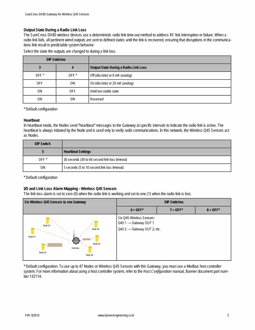
Output State During a Radio Link Loss The SureCross DX80 wireless devices use a deterministic radio link time-out method to address RF link interruption or failure. When a radio link fails, all pertinent wired outputs are sent to defined states until the link is recovered, ensuring that disruptions in the communica- tions link result in predictable system behavior. Select the state the outputs are changed to during a link loss.
DIP Switches
3 4 Output State During a Radio Link Loss
OFF * OFF * Off (discrete) or 0 mA (analog)
OFF ON On (discrete) or 20 mA (analog)
ON OFF Hold last stable state
ON ON Reserved
* Default configuration
Heartbeat In heartbeat mode, the Nodes send "heartbeat" messages to the Gateway at specific intervals to indicate the radio link is active. The heartbeat is always initiated by the Node and is used only to verify radio communications. In this network, the Wireless Q45 Sensors act as Nodes.
DIP Switch
5 Heartbeat Settings
OFF * 30 seconds (30 to 60 second link loss timeout)
ON 5 seconds (5 to 10 second link loss timeout)
* Default configuration
I/O and Link Loss Alarm Mapping - Wireless Q45 Sensors The link loss alarm is set to zero (0) when the radio link is working and set to one (1) when the radio link is lost.
Six Wireless Q45 Sensors to one Gateway DIP Switches
6 = OFF* 7 = OFF* 8 = OFF*
Node 02 Node 04
Node 01
Node 05
Gateway
Node 03 Node 06
Six Q45 Wireless Sensors: Q45 1 → Gateway OUT 1 Q45 2 → Gateway OUT 2; etc.
* Default configuration. To use up to 47 Nodes or Wireless Q45 Sensors with this Gateway, you must use a Modbus host controllersystem. For more information about using a host controller system, refer to the Host Configuration manual, Banner document part num- ber 132114.

SureCross DX80 Gateway for Wireless Q45 Sensors
4 www.bannerengineering.co.kr P/N 182818
Three Wireless Q45 Sensors to one Gateway DIP Switches
6 = OFF 7 = OFF 8 = ON
Node 02 Node 03
Node 01
Gateway
Three Wireless Q45 Sensors and three link loss: Q45 1 → Gateway OUT 1; Link loss alarm for Q45 1 → Gateway OUT 2 Q45 2 → Gateway OUT 3; Link loss alarm for Q45 2 → Gateway OUT 4 Q45 3 → Gateway OUT 5; Link loss alarm for Q45 3 → Gateway OUT 6
Three Wireless Q45 Sensors to one Gateway DIP Switches
6 = OFF 7 = ON 8 = OFF
Node 02 Node 03
Node 01
Gateway
Three Wireless Q45 Sensors, two inputs each: Q45 1, IN 1 → Gateway OUT 1; Q45 1, IN 2 → Gateway OUT 2 Q45 2, IN 1 → Gateway OUT 3; Q45 2, IN 2 → Gateway OUT 4 Q45 3, IN 1 → Gateway OUT 5; Q45 3, IN 2 → Gateway OUT 6
Two Wireless Q45 Sensors to one Gateway DIP Switches
6 = OFF 7 = ON 8 = ON
Two Wireless Q45 Sensors, two inputs each, with link loss: Q45 1, IN 1 → Gateway OUT 1
Q45 1, IN 2 → Gateway OUT 2
Link loss alarm for Q45 1 → Gateway OUT 3
Q45 2, IN 1 → Gateway OUT 4
Q45 2, IN 2 → Gateway OUT 5
Link loss alarm for Q45 2 → Gateway OUT 6
I/O and Link Loss Mapping - Nodes and Gateways
One Node to one Gateway DIP Switches
6 = ON 7 = OFF 8 = OFF
Node 01 Gateway
One SureCross DX80 Node with 6 inputs and 6 outputs: Node 1, IN 1 → Gateway OUT 1; Gateway IN 1 → Node 1, OUT 1 Node 1, IN 2 → Gateway OUT 2; Gateway IN 2 → Node 1, OUT 2 Node 1, IN 3 → Gateway OUT 3; Gateway IN 3 → Node 1, OUT 3 Node 1, IN 4 → Gateway OUT 4; Gateway IN 4 → Node 1, OUT 4 Node 1, IN 5 → Gateway OUT 5; Gateway IN 5 → Node 1, OUT 5 Node 1, IN 6 → Gateway OUT 6; Gateway IN 6 → Node 1, OUT 6

SureCross DX80 Gateway for Wireless Q45 Sensors
P/N 182818 www.bannerengineering.co.kr 5
Two Nodes to one Gateway DIP Switches
6 = ON 7 = OFF 8 = ON
Node 02
Node 01 Gateway
Two SureCross DX80 Nodes, each with 3 inputs and 3 outputs Node 1, IN 1 → Gateway OUT 1; Gateway IN 1 → Node 1, OUT 1 Node 1, IN 2 → Gateway OUT 2; Gateway IN 2 → Node 1, OUT 2 Node 1, IN 3 → Gateway OUT 3; Gateway IN 3 → Node 1, OUT 3 Node 2, IN 1 → Gateway OUT 4; Gateway IN 4 → Node 2, OUT 1 Node 2, IN 2 → Gateway OUT 5; Gateway IN 5 → Node 2, OUT 2 Node 2, IN 3 → Gateway OUT 6; Gateway IN 6 → Node 2, OUT 3
Three Nodes to one Gateway DIP Switches
6 = ON 7 = ON 8 = OFF
Node 02 Node 03
Node 01 Gateway
Three SureCross DX80 Nodes, each with 2 inputs and 2 outputs Node 1, IN 1 → Gateway OUT 1; Gateway IN 1 → Node 1, OUT 1
Node 1, IN 2 → Gateway OUT 2; Gateway IN 2 → Node 1, OUT 2
Node 2, IN 1 → Gateway OUT 3; Gateway IN 3 → Node 2, OUT 1
Node 2, IN 2 → Gateway OUT 4; Gateway IN 4 → Node 2, OUT 2
Node 3, IN 1 → Gateway OUT 5; Gateway IN 5 → Node 3, OUT 1
Node 3, IN 2 → Gateway OUT 6; Gateway IN 6 → Node 3, OUT 2
Six Nodes to one Gateway DIP Switches
6 = ON 7 = ON 8 = ON
Node 02 Node 03
Node 01 Gateway
Node 04
Node 06
Node 05
Six SureCross DX80 Nodes, each with 1 input and 1 output Node 1, IN 1 → Gateway OUT 1; Gateway IN 1 → Node 1, OUT 1 Node 2, IN 1 → Gateway OUT 2; Gateway IN 2 → Node 2, OUT 1 Node 3, IN 1 → Gateway OUT 3; Gateway IN 3 → Node 3, OUT 1 Node 4, IN 1 → Gateway OUT 4; Gateway IN 4 → Node 4, OUT 1 Node 5, IN 1 → Gateway OUT 5; Gateway IN 5 → Node 5, OUT 1 Node 6, IN 1 → Gateway OUT 6; Gateway IN 6 → Node 6, OUT 1

SureCross DX80 Gateway for Wireless Q45 Sensors
6 www.bannerengineering.co.kr P/N 182818
PWR PWR
Wire the Gateway's I/O
Wire the Gateway’s I/O
GND
DO6
DO5
DO4
DO3
DO2
DO1
GND
DI6
DI5
DI4
DI3
DI2
DI1
DI1 DI2 DI3 DI4 DI5 DI6 V+ V- V-
DO1 DO2 DO3 DO4 DO5 DO6 Tx/+ Rx/-
V+
DIx. Discrete IN x. DOx. Discrete OUT x. GND. Ground/dc common connection. PWR. Power, 10 to 30V dc power connection.
RX/-. Serial comms line TX/+. Serial comms line V+. Power, 10 to 30V dc power connection. V-. Ground/dc common connection.
Discrete Input Wiring for PNP Sensors Discrete Output Wiring (PNP)
10-30V dc PWR
DIx
PWR
DOx
GND
Load
10-30V dc
dc common
Modbus Register Table for the Gateway with Switch-Based Mapping I/O Modbus Holding
Register (Gateway) I/O Type I/O Range Holding Register Represen-
tation Terminal Block
Labels
Min. Max. Min. (Dec.) Max. (Dec.)
1 1 Discrete IN 1 0 1 0 1 DI1
2 2 Discrete IN 2 0 1 0 1 DI2
3 3 Discrete IN 3 0 1 0 1 DI3
4 4 Discrete IN 4 0 1 0 1 DI4
5 5 Discrete IN 5 0 1 0 1 DI5
6 6 Discrete IN 6 0 1 0 1 DI6
7 7 Reserved
8 8 Device Message
9 9 Discrete OUT 1 0 1 0 1 DO1
10 10 Discrete OUT 2 0 1 0 1 DO2
11 11 Discrete OUT 3 0 1 0 1 DO3
12 12 Discrete OUT 4 0 1 0 1 DO4
13 13 Discrete OUT 5 0 1 0 1 DO5

SureCross DX80 Gateway for Wireless Q45 Sensors
P/N 182818 www.bannerengineering.co.kr 7
I/O Modbus Holding Register (Gateway)
I/O Type I/O Range Holding Register Represen- tation
Terminal Block Labels
Min. Max. Min. (Dec.) Max. (Dec.)
14 14 Discrete OUT 6 0 1 0 1 DO6
15 15 Control Message
16 16 Reserved
Discrete Bit-Packed Registers Discrete bit-packed registers include the discrete status registers, discrete inputs, and discrete outputs. Bit packing involves using a single register, or range of contiguous registers, to represent I/O values. When networks use similar Nodes to gather data using the same I/O registers for each Node, discrete data from multiple Nodes can be bit packed into a single register on the Gateway. The bit-packed data is arranged by I/O point starting at Modbus register 6601. For example, Discrete IN 1 for all the Nodes in the network is stored in three contiguous 16-bit registers. The most efficient way to read (or write) discrete data from a SureCross® DX80 Gateway is by using these bit-packed registers because users can read or write registers for all devices using one Modbus message. The following registers contain discrete bit-packed I/O val- ues for the Gateway and all Nodes. Values are stored first for the Gateway, then for each Node in order of Node address.
Bit-Packed Device Status R egisters
Bit Position Register Address 15 14 13 12 11 10 9 8 7 6 5 4 3 2 1 0 6601 Node 15 Node 14 Node 13 Node 12 Node 11 Node 10 Node 9 Node 8 Node 7 Node 6 Node 5 Node 4 Node 3 Node 2 Node 1 Gateway 6602 Node 31 Node 30 Node 29 Node 28 Node 27 Node 26 Node 25 Node 24 Node 23 Node 22 Node 21 Node 20 Node 19 Node 18 Node 17 Node 16 6603 Node 47 Node 46 Node 45 Node 44 Node 43 Node 42 Node 41 Node 40 Node 39 Node 38 Node 37 Node 36 Node 35 Node 34 Node 33 Node 32
Bit-Packed Discrete Input 1
Bit Position Register Address 15 14 13 12 11 10 9 8 7 6 5 4 3 2 1 0 6611 Node 15 Node 14 Node 13 Node 12 Node 11 Node 10 Node 9 Node 8 Node 7 Node 6 Node 5 Node 4 Node 3 Node 2 Node 1 Gateway 6612 Node 31 Node 30 Node 29 Node 28 Node 27 Node 26 Node 25 Node 24 Node 23 Node 22 Node 21 Node 20 Node 19 Node 18 Node 17 Node 16 6613 Node 47 Node 46 Node 45 Node 44 Node 43 Node 42 Node 41 Node 40 Node 39 Node 38 Node 37 Node 36 Node 35 Node 34 Node 33 Node 32
Bit-Packed Discrete Output 1
Bit Position Register Address 15 14 13 12 11 10 9 8 7 6 5 4 3 2 1 0 6691 Node 15 Node 14 Node 13 Node 12 Node 11 Node 10 Node 9 Node 8 Node 7 Node 6 Node 5 Node 4 Node 3 Node 2 Node 1 Gateway 6692 Node 31 Node 30 Node 29 Node 28 Node 27 Node 26 Node 25 Node 24 Node 23 Node 22 Node 21 Node 20 Node 19 Node 18 Node 17 Node 16 6693 Node 47 Node 46 Node 45 Node 44 Node 43 Node 42 Node 41 Node 40 Node 39 Node 38 Node 37 Node 36 Node 35 Node 34 Node 33 Node 32
Inputs Outputs
Modbus Register Ad- dress (Decimal)
Description (Inputs) Modbus Register Ad- dress (Decimal)
Description (Outputs)
6601-6603 Status for all devices
6611-6613 Input 1 from all devices 6691–6693 Output 1 from all devices
6621-6623 Input 2 from all devices 6701–6703 Output 2 from all devices
6631-6633 Input 3 from all devices 6711–6713 Output 3 from all devices
6641-6643 Input 4 from all devices 6721–6723 Output 4 from all devices
6651-6653 Input 5 from all devices 6731–6733 Output 5 from all devices
6661-6663 Input 6 from all devices 6741–6743 Output 6 from all devices
6671-6673 Input 7 from all devices 6751–6753 Output 7 from all devices
6681-6683 Input 8 from all devices
Status registers (6601-6603) contain a bit-packed representation defining the devices that are operational in the wireless system.
SureCross DX80 Gateway for Wireless Q45 Sensors
8 www.bannerengineering.co.kr P/N 182818
A one (1) written to the Discrete Status Register area indicates the device is active within the wireless system. A zero (0) indicates the device is not active within the wireless network. Input registers from all devices use Modbus registers 6611 through 6683 to organize the least significant bit into a sequential array of registers. The first register contains the least significant bit from the input values for the Gateway through Node 15. The second register contains the input values for Node 16 through Node 31, and the third register contains the input values for Nodes 32 through 47. For discrete inputs, only the least significant bit is used. For analog inputs, the least significant bit indicates if the analog value is above or below the selected threshold value (when using the threshold parameter). For example, a least significant bit of one (1) indicates the analog value is above the selected threshold value. A least significant bit of zero (0) indicates the analog value is below the threshold value. Output registers from all devices use Modbus registers 6691 through 6753 to organize the least significant bit into a sequential array of registers. Output 8 (I/O point 16) cannot be written using the discrete format.
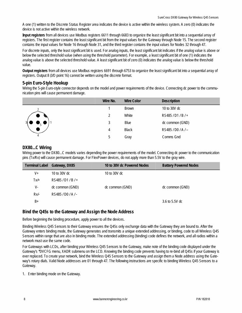
5-pin Euro-Style Hookup Wiring the 5-pin Euro-style connector depends on the model and power requirements of the device. Connecting dc power to the commu- nication pins will cause permanent damage.
Wire No. Wire Color Description
2 1 Brown 10 to 30V dc
2 White RS485 / D1 / B / + 3
5 1 3 Blue dc common (GND)
4 Black RS485 / D0 / A / – 4 5 Gray Comms Gnd
DX80...C Wiring Wiring power to the DX80...C models varies depending the power requirements of the model. Connecting dc power to the communication pins (Tx/Rx) will cause permanent damage. For FlexPower devices, do not apply more than 5.5V to the gray wire.
Terminal Label Gateway, DX85 10 to 30V dc Powered Nodes Battery Powered Nodes
V+ 10 to 30V dc 10 to 30V dc Tx/+ RS485 / D1 / B / +
V- dc common (GND) dc common (GND) dc common (GND)
Rx/- RS485 / D0 / A / -
B+ 3.6 to 5.5V dc
Bind the Q45s to the Gateway and Assign the Node Address Before beginning the binding procedure, apply power to all the devices.
Binding Wireless Q45 Sensors to their Gateway ensures the Q45s only exchange data with the Gateway they are bound to. After the Gateway enters binding mode, the Gateway generates and transmits a unique extended addressing, or binding, code to all Wireless Q45 Sensors within range that are also in binding mode. The extended addressing (binding) code defines the network, and all radios within a network must use the same code. For Gateways with LCDs, after binding your Wireless Q45 Sensors to the Gateway, make note of the binding code displayed under the Gateway's *DVCFG menu, XADR submenu on the LCD. Knowing the binding code prevents having to re-bind all Q45s if your Gateway is ever replaced. To create your network, bind the Wireless Q45 Sensors to the Gateway and assign them a Node address using the Gate- way's rotary dials. Valid Node addresses are 01 through 47. The following instructions are specific to binding Wireless Q45 Sensors to a Gateway.
1. Enter binding mode on the Gateway.

SureCross DX80 Gateway for Wireless Q45 Sensors
P/N 182818 www.bannerengineering.co.kr 9
Model To Enter Binding Mode:
-B2Q Board Modules Triple-click the button.
-Q and -QC Gateway Radios Triple-click button 2.
On the board modules, the green and red LED flashes. On the -Q and -QC Gateway models, both LEDs flash red. 2. Assign the Q45 a Node address using the Gateway's rotary dials. Use the left rotary dial for the left digit and the right rotary dial for
the right digit. For example, to assign your Q45 to Node 01, set the left dial to 0 and the right dial to 1. 3. Loosen the clamp plate on the top of the Wireless Q45 Sensor and lift the cover.4. Enter binding mode on the Wireless Q45 Sensor by triple-clicking the button.
The red and green LEDs flash alternately and the sensor searches for a Gateway in binding mode. After the Q45 is bound, the LEDsstay solid momentarily, then they flash together four times. The Q45 exits binding mode.
5. Label the sensor with the Q45's Node address number and place the sticker on the Wireless Q45 Sensor.6. Repeat steps 2 through 5 for as many Wireless Q45 Sensors as are needed for your network.7. After binding all Wireless Q45 Sensors, exit binding mode on the Gateway.
Model To Exit Binding Mode:
-B2Q Board Modules Double-click the button.
-Q and -QC Gateway Radios Double-click button 2.
Verify Communication Between the Gateway and the Wireless Q45 Sensors After powering up and binding the Wireless Q45 Sensors to the Gateway, verify all devices are communicating properly. Verify the Gate- way's LED 1 is green. Until communication is established with the Gateway, the Q45's red LED flashes. After communication is establish- ed, the Q45's green LED flashes. When testing the Gateway and Wireless Q45 Sensors, verify all radios are at least two meters apart or the communications may fail.
Conducting a Site Survey (Gateway and Nodes) Conducting a Site Survey, also known as an RSSI (Radio Signal Strength Indication), analyzes the radio communications link between the Gateway and any Node within the network by analyzing the radio signal strength of received data packets and reporting the number of missed packets that required a retry. Perform a Site Survey before permanently installing the radio network to ensure reliable communication. Activate Site Survey mode from either the Gateway buttons or the Gateway Modbus holding register 15. Only the Gateway can initiate a Site Survey, and the Site Survey analyzes the radio communications link with one Node at a time.
Conducting a Site Survey Using the Menu System Follow these steps to initiate a Site Survey using the Gateway’s buttons and menu system.
1. Remove the rotary dial access cover.2. To check the status of Node 1, change the Gateway’s right rotary dial to 1.
The Gateway is now enabled to read the status of Node 1; the display scrolls through the Node’s I/O status.3. Single-click button 1 to scroll across the menu levels until reaching the Site Survey (SITE) menu.4. Single-click button 2 to enter the Site Survey menu.5. Single-click button 2 to begin conducting a Site Survey with the Node selected in step 2.
The Gateway analyzes the quality of the signal from the selected Node by counting the number of data packets it receives from theNode.
6. Examine reception readings (M, R, Y, G) of the Gateway at various locations. Note that the numbers displayed are a percentage. Mdisplays the percent of missed packets while R, Y, and G display the percentage of received packets at a given signal strength.M = Percentage of missed packets; R = RED marginal signal; Y = YELLOW good signal; G = GREEN excellent signalRecord the results if you need troubleshooting assistance from the factory.
7. Change the Gateway's right rotary dial to conduct a Site Survey with another Node and repeat steps 2 through 6.8. To end the Site Survey, double-click button 2.9. Change the Gateway's right rotary dial back to 0.
The LCD displays the device readings for the Gateway.

SureCross DX80 Gateway for Wireless Q45 Sensors
10 www.bannerengineering.co.kr P/N 182818
10. Double-click button 2 to move back to the top level menu.11. Single-click button 1 to return to RUN mode.12. Install the rotary dial access cover, referring to the Installation section of the manual to create an IP67 seal.
Interpreting the Site Survey Results Site Survey results are listed as a percentage of data packets received and indicate the signal strength of the received signal.
Result Description
Green Packets received at a strong signal strength. A strong signal strength is greater than −90 dBm at the receiver.
Yellow Packets received at a good signal strength. A good signal is between −90 and −100 dBm at the receiver.
Red Packets received at a weak signal strength. A weak signal is less than −100 dBm at the receiver.
Missed Packets not received on the first transmission and requiring a retry.
Judging if the reliability of a network’s signal meets the needs of the application is not simply a matter of green, yellow, and red packets received. In normal operating mode, when data packets are not received, the transmitter re-sends the packet until all data is received. For slow monitoring applications such as a tank farm, where data is required in terms of seconds or minutes, receiving most of the data in the ‘red’ range, indicating a weak but reliable signal, transmits enough data for accurate monitoring. Nodes positioned near the outside range of the radio signal may have 90% of the data packets received in the red zone, again indicating a weak, but reliable signal. A good rule of thumb is to keep the missed packets average to less than 40%. When the network misses more than 40% of the data packets, the signal is usually too unreliable or obstacles may be interfering with the signal. When Site Survey reports the missed packets are 40% or higher, improve the radio system performance by:
• Mounting the network’s antennas higher,• Using higher gain antennas, or• Adding data radios to the network.
Mounting the devices’ antennas higher allows the radio signal to clear obstacles in the area and improves the line of sight between SureCross® devices. Higher gain antennas focus the energy of the radio signal in a specific direction and extend the signal’s range. Using data radios is another option to consider when trying to extend the range of a radio network. For more information on data radios, please refer to Banner’s white paper on range extension on www.bannerengineering.com/surecross.
Specifications
Range 2.4 GHz: Up to 3.2 kilometers (2 miles)
Transmit Power 2.4 GHz: 18 dBm (65 mW) conducted, less than or equal to 20 dBm (100 mW) EIRP
Radio and General
Power Requirements: +10 to 30V dc (Outside the USA: +12 to 24V dc, ±10%). (See UL section below for any applica- ble UL specifications) Consumption: Less than 1.4 W (60 mA) at 24V dc

SureCross DX80 Gateway for Wireless Q45 Sensors
P/N 182818 www.bannerengineering.co.kr 11
2.4 GHz Compliance
Radio and General
Housing FCC ID UE300DX80-2400 - This device complies with FCC Part 15, Subpart C, 15.247 ETSI/EN: In accordance with EN 300 328: V1.7.1 (2006-05) IC: 7044A-DX8024
Spread Spectrum Technology FHSS (Frequency Hopping Spread Spectrum)
Radio range is with the 2 dB antenna that ships with the product. High-gain antennas are available, but the range depends on the environment and line of sight. To determine the range of your wire- less network, perform a Site Survey.
Polycarbonate housing and rotary dial cover; polyester labels; EDPM rubber cover gasket; nitrile rubber, non- sulphur cured button covers Weight: 0.26 kg (0.57 lbs) Mounting: #10 or M5 (SS M5 hardware included) Max. Tightening Torque: 0.56 N·m (5 lbf·in)
Antenna Connection Ext. Reverse Polarity SMA, 50 Ohms Max Tightening Torque: 0.45 N·m (4 lbf·in)
Interface Indicators: Red/Green Power LED, Red/Yellow Signal LED
Wiring Access Two 1/2-inch NPT
For European applications, power the DX80 from a Limited Power Source as defined in EN 60950-1.
Discrete Inputs Rating: 3 mA max current at 30V dc Sample Rate: 62.5 milliseconds Report Rate: On change of state ON Condition (PNP): Greater than 8V OFF Condition (PNP): Less than 5V
Inputs and Outputs
Discrete Outputs Update Rate: 125 milliseconds ON Condition: Supply minus 2V OFF Condition: Less than 2V Output State Following Timeout: OFF
Discrete Output Rating (PNP) 100 mA max current at 30V dc ON-State Saturation: Less than 3V at 100 mA OFF-state Leakage: Less than 10 μA
Hardware (RS-485) Interface: 2-wire half-duplex RS-485 Baud rates: 9.6k, 19.2k (default), or 38.4k
Communication and Environmental
Environmental Conditions Rating: IEC IP67; NEMA 6; (See UL section below for any applicable UL specifications)
Data format: 8 data bits, no parity, 1 stop bit Protocol
Modbus RTU Operating the devices at the maximum operating conditions for ex- tended periods can shorten the life of the device.
Operating Temperature: −40 to +85 °C Operating Humidity: 95% max. relative (non-condens- ing) Radiated Immunity: 10 V/m, 80-2700 MHz (EN61000-6-2)
Shock and Vibration IEC 68-2-6 and IEC 68-2-7 Shock: 30g, 11 millisecond half sine wave, 18 shocks Vibration: 0.5 mm p-p, 10 to 60 Hz
Warnings Antenna Installations. Install and properly ground a qualified surge suppressor when installing a remote antenna system. Remote antenna configurations installed without surge suppressors invalidate the manufacturer's warranty. Keep the ground wire as short as possible and make all ground connections to a single-point ground system to ensure no ground loops are created. No surge suppressor can absorb all lightning strikes; do not touch the SureCross® device or any equipment connected to the SureCross device during a thunderstorm.

SureCross DX80 Gateway for Wireless Q45 Sensors
www.bannerengineering.co.kr
Exporting SureCross Radios. It is our intent to fully comply with all national and regional regulations regarding radio frequency emissions. Custom- ers who want to re-export this product to a country other than that to which it was sold must ensure the device is approved in the destina- tion country. A list of approved countries appears in the Radio Certifications section of the product manual. The SureCross wireless products were certified for use in these countries using the antenna that ships with the product. When using other antennas, verify you are not exceeding the transmit power levels allowed by local governing agencies. Consult with Banner Engineering Corp. if the destination country is not on this list.
Violating Warnings. The manufacturer does not take responsibility for the violation of any warning listed in this document. Make no modifications to this product; any modifications to this product not expressly approved by Banner Engineering could void the user’s authority to operate the product. All specifications published in this document are subject to change; Banner reserves the right to modify product specifications or to update docu- mentation at any time. For the most recent version of any documentation, refer to: www.bannerengineering.com. © 2006-2013 Banner Engineering Corp. All rights reserved.
Banner Engineering Corp Limited Warranty Banner Engineering Corp. warrants its products to be free from defects in material and workmanship for one year following the date of shipment. Banner Engineering Corp. will repair or replace, free of charge, any product of its manufacture which, at the time it is returned to the factory, is found to have been defective during the warranty period. This warranty does not cover damage or liability for misuse, abuse, or the improper application or installation of the Banner product. THIS LIMITED WARRANTY IS EXCLUSIVE AND IN LIEU OF ALL OTHER WARRANTIES WHETHER EXPRESS OR IMPLIED (INCLUDING, WITHOUT LIMITATION, ANY WARRANTY OF MERCHANTABILITY OR FITNESS FOR A PARTICULAR PURPOSE), AND WHETHER ARISING UNDER COURSE OF PERFORMANCE, COURSE OF DEALING OR TRADE USAGE. This Warranty is exclusive and limited to repair or, at the discretion of Banner Engineering Corp., replacement. IN NO EVENT SHALL BANNER ENGINEERING CORP. BE LIABLE TO BUYER OR ANY OTHER PERSON OR ENTITY FOR ANY EXTRA COSTS, EXPENSES, LOSSES, LOSS OF PROFITS, OR ANY INCIDENTAL, CONSEQUENTIAL OR SPECIAL DAMAGES RESULTING FROM ANY PRODUCT DEFECT OR FROM THE USE OR INABILITY TO USE THE PRODUCT, WHETH- ER ARISING IN CONTRACT OR WARRANTY, STATUTE, TORT, STRICT LIABILITY, NEGLIGENCE, OR OTHERWISE. Banner Engineering Corp. reserves the right to change, modify or improve the design of the product without assuming any obligations or liabilities relating to any product previously manufactured by Banner Engineering Corp.