Flowserve 2 Control valve actuators 2.2 Selection of control valve ...

The selection of mechanical actuatorsbased on performance indices
B y J. E. Huber, N. A. Fleck and M. F. Ashby
Department of Engineering, Cambridge University, Trumpington Street,Cambridge CB2 1PZ, UK
A method is presented for selecting the type of actuator best suited to a giventask, in the early stages of engineering design. The selection is based on matchingperformance characteristics of the actuator, such as force and displacement, to therequirements of the given task. The performance characteristics are estimated frommanufacturers’ data and from simple models of performance limitation such as heatgeneration and resonance. Characteristics are presented in a graphical form whichallows for a direct and systematic comparison of widely different systems of actuation.The actuators considered include man-made actuators (such as hydraulic, solenoidand shape memory alloy) and naturally occurring actuators (such as the muscles ofanimals and plants).
1. Introduction
Actuators provide the driving force and motion for a variety of natural and man-made requirements; typical examples are listed in table 1. In each case a mechanicalaction is activated in response to a control signal. Naturally occurring actuators in-clude the muscles of animals and plants, and man-made actuators include hydraulics,pneumatics and solenoids. Other man-made actuators, such as piezoelectric, shapememory alloy and magnetostrictive devices, are based on shape-changing materials;these are used increasingly in novel applications. For example, piezoelectric actu-ators are used in precision positioning devices such as the reading heads in videocassette recorders and compact disc players. They have been proposed for active ma-terials and structures (Shen 1994), adjustable aerodynamic surfaces (Barrett 1992),vibration damping (Crawley & de Luis 1987) and noise cancellation. Shape memoryalloys have found applications mainly where a single contracting stroke is required,such as in pipe couplings and orthodontic wires; cyclic applications include actu-ators in robot end effectors (Venison 1986; Furnya & Shimada 1991) and satellitestructure deployment (McDonald Schetky 1991). Magnetostrictive actuators havefound relatively few applications; suggested uses include vibration isolation and ac-tive aerodynamic surfaces (Bothwell et al. 1995). A description of each of the classesof actuator discussed in this article is given in the appendix. Energy storage devicessuch as springs, flywheels and weights are not included in the analysis.
Given the wide variety of existing applications and actuators, some means ofmatching the requirements of an application to the performance characteristics of anactuator is desirable. The mechanical requirements of an application can be expressed
Proc. R. Soc. Lond. A (1997) 453, 2185–2205 c© 1997 The Royal SocietyPrinted in Great Britain 2185 TEX Paper

2186 J. E. Huber, N. A. Fleck and M. F. Ashby
Table 1. Typical applications of actuators
aerospace automotive industrial equipment
flight control surfaces braking automation equipmentlanding gear movement tappets numerically controlled
machinesnose wheel steering active suspension pressesair brakes active engine mounts lifting equipmentpowered doors/hatches airbag deployment
electrical goods developing technologies instrumentation
automatic switches/thermostats active control of structures atomic force microscopevideo/compact disc reading head vibration suppressioncamera auto-focus active materials
surgical equipmentroboticsspace structure deployment
in terms of force, displacement, stiffness, size, mass, response time (or operating fre-quency), power, efficiency and resolution. These must be matched to the performancecharacteristics of an actuator in order to determine whether the actuator can givethe performance required for the application. Requirements such as cost, durability,maintenance, and environmental impact are less precisely defined and are not consid-ered here. This article provides an overview of the range of actuation systems, givesa quantitative comparison of their performances, and presents examples of a system-atic selection procedure for actuators. The mechanical performances of man-madeactuators are compared with the corresponding performances of naturally occurringsystems; this comparison is relevant to the design of prosthetic devices, where it isnecessary to match the performance of a man-made system with that of a naturalsystem.
(a ) DefinitionsActuators offer a wide variety of performance and operate in many different ways.
For the present analysis an actuator is defined to be a controllable work-producingmachine. In order to provide a quantitative means of comparison, the scope of thisarticle is restricted to actuators which operate in a linear fashion, causing a finitechange in length. The study does not deal with motors which are able to produce (inprinciple) infinite displacements—these could be considered in a separate analysis.A number of definitions which assist the comparison are listed in table 2.
2. Performance characteristics of actuators
The maximum actuation stress, σmax, and maximum actuation strain, εmax, arebasic characteristics of an actuator. For a given size of actuator they limit the forceand displacement. Alternatively, given the design values for the required forces anddisplacements, the size and shape of a suitable actuator may be estimated. The stressversus strain (σ–ε) characteristic of an actuator is not a single curve; it is a family
Proc. R. Soc. Lond. A (1997)
The selection of mechanical actuators 2187
Table 2. Definitions
performance characteristic definition
actuation stress (σ) The applied force per unit cross-sectional areaof an actuator.
maximum The maximum value of actuation stressactuation stress (σmax) in a single stroke which produces maximum work output.
actuation strain (ε) The nominal strain produced by an actuator;an actuator of initial length L extends to a totallength of (1 + ε)L.
maximum The maximum value of actuation strain inactuation strain (εmax) a single stroke which produces maximum work output.
actuator density (ρ) The ratio of mass to initial volume of an actuator.(We neglect the contribution to mass from powersupplies, external fixtures and peripheral devices.For example, in the mass of a hydraulic cylinder,we include the working fluid and the cylinder,but neglect the compressor, servo-valve,cooling system and mounting fixtures.)
actuator modulus (E) The ratio of a small increment in σ to the correspondingsmall increment in ε when the control signal to anactuator is held constant. (In general this differs fromthe measured modulus dσ/dε which dependsupon the control signal.)
volumetric power (p) The mechanical power output per unit initial volumein sustainable cyclic operation.
efficiency (η) The ratio of mechanical work output to energy inputduring a complete cycle in cyclic operation.
strain resolution (εmin) The smallest step increment of ε(order of magnitude approximations are given).
of curves which depend on the control signal and the external constraints. As anexample, several stress versus strain curves available from a hydraulic actuator areshown in figure 1. If the work output per unit volume is maximized, then the σ–εcurves shown in figure 2 result.
The curves in figure 2 are based on a constant actuation stress for hydraulic andpneumatic actuators, and a linear relationship between actuation stress and strain inpiezoelectric, magnetostrictive and thermal expansion actuators. For shape memoryalloys, the σ–ε curve depends upon the material and the operating conditions. Theshape shown in figure 2 corresponds to the general form found by a variety of exper-imenters (Bidaux et al. 1994; Shaw & Kyriakides 1995). The σ–ε curve for muscleis based on data in the literature of muscle physiology (Woledge 1985; McMahon1984). The product σmaxεmax is an estimate of the maximum work per unit volumein a single stroke. More precisely, a dimensionless stroke work coefficient Cs can bedefined as the ratio of the maximum work done in a single stroke to the productσmaxεmax:
Cs =∫ 1
0
σ
σmaxd(
ε
εmax
). (2.1)
Proc. R. Soc. Lond. A (1997)

2188 J. E. Huber, N. A. Fleck and M. F. Ashby
εmax0
σ
σmax
ε
slope -E
Figure 1. Several stress versus strain characteristics for a hydraulic actuator.
ε/εmax
Moving coil/Solenoid
σ/σmax
1
10
Piezoelectric/Magnetostrictive/Thermal expansion
Hydraulic/Pneumatic
Single muscleSingle shape memoryalloy wire
Figure 2. Normalized single stroke stress versus strain curves. The curves show theapproximate shapes of the σ versus ε curves which maximize work per unit volume.
The coefficient Cs lies in the range zero to unity and is an efficiency measure of theshape of the σ–ε curve.
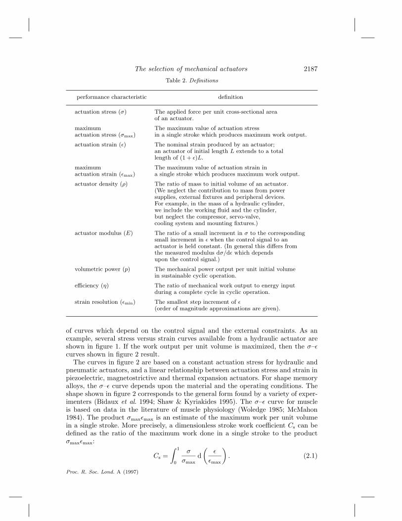
Now consider cyclic operation of an actuator. Some actuators are intrinsically wellsuited to cyclic operation and some are not. Shape memory alloys, solenoids, andorganic muscles typically provide a single action and require an external system toreset them for cyclic operation. In shape memory alloys the resetting force providesa severe limitation on cyclic operation. Approximate σ–ε curves for cyclic operationproducing maximum work per unit volume per cycle are shown in figure 3. Forsimplicity, the curves for single acting systems are based on the action of a pair ofactuators operating antagonistically, as shown in figure 4.
The curves in figure 3 relate to low-frequency operation, where inertial and ratelimiting-effects are negligible. In this operating regime, the work available per cycleis 4Ccσmaxεmax, where Cc is a dimensionless cyclic work coefficient defined in cyclicoperation with maximum work output per cycle by:
Cc = 14
∮σ
σmaxd(
ε
εmax
). (2.2)
The coefficient Cc lies in the range zero to unity and is an efficiency measure ofthe shape of the σ–ε curve in cyclic operation. Values for Cs and Cc are given intable 3.
At low frequency, the power per unit volume, p, is proportional to the frequency,f , of operation, giving p = 4fCcσmaxεmax. At high frequency the performance ap-
Proc. R. Soc. Lond. A (1997)
The selection of mechanical actuators 2189
–1
–1 1
1Piezoelectric/Magnetostrictive/Thermal expansion
σ/σmax
ε/εmax
Hydraulic/PneumaticMoving coil/Solenoid
Shape memory alloywires (opposed pair)
Antagonistic musclepair
Figure 3. Normalized cyclic stress versus strain curves. The figure shows the approximate shapesof the cyclic σ versus ε curves which maximize work per unit volume per cycle at low frequency.
Load, Displacement
Actuator 1 Actuator 2
Length L
Figure 4. Antagonistic pair of actuators.
proaches a limit either in the form of a maximum power per unit volume, pmax, orof a maximum frequency of operation, fmax. The limit fmax is determined as follows.In devices where mechanical resonance places a limit on the operating frequency(piezoelectric and magnetostrictive devices), fmax is defined by the frequency of firstresonance. This value depends on the size of the actuator, and the appropriate lengthdimension is based on the smallest length available using current manufacturing prac-tice. In devices which rely on temperature change for actuation (shape memory alloyand thermal expansion) the value of fmax is based on the time required to transferheat into and out of the actuator. For these devices it is found that heat transferis limited by convection at the surface of the actuator, and the heat transfer co-efficient is typically in the range 100–1000 W m−2 K−1. The time required for heattransfer also depends on a length dimension and, as with resonance, the smallestavailable size has been used to give an approximate bound on frequency. In otherdevices frequency limits are taken from the sources referred to in the appendix. Itis recognized that only an approximate bound on operating frequency can be givenwhen discussing devices in such a general way. However, the resulting values for fmaxvary by about seven orders of magnitude between different classes of actuator, andso an approximate analysis is sufficient to distinguish their performances. Above thefrequency fmax some actuators are inoperable. Others suffer a reduction in power dueto the inertia of moving parts; the amplitude of cyclic actuation drops to keep theinertial forces within the actuator’s capability, and the power varies with frequencyapproximately as 1/f2.
The power limit pmax is based, in piezoelectric and magnetostrictive devices, onthe maximum power to avoid overheating. In hydraulic and pneumatic actuators alimit is provided by the maximum sliding speed for the sealing system. The aboveanalysis results in a power versus frequency characteristic, for a particular actuator,of the form shown in figure 5.
Proc. R. Soc. Lond. A (1997)

2190 J. E. Huber, N. A. Fleck and M. F. Ashby
p = 4 f Ccσmaxεmax
log ( f )
log(
p)
p = pmax
f = fmax
p ∝ 1 / f 2
Figure 5. Typical shape of the volumetric power, p, versus frequency, f , limiting envelope foran actuator.
3. Actuator property charts
A systematic procedure for the selection of materials in engineering design, em-ploying performance indices and material property charts, has been demonstrated byAshby and co-workers (Ashby 1989, 1992; Ashby & Cebon 1993). When the charac-teristics of actuators are displayed on property charts, certain relationships betweenthe different classes of actuators become evident. Consider, for example, a chartwhich displays the feasible combinations of actuation stress, σ, and actuation strain,ε, as shown in figure 6. The data in figure 6 are drawn from a database of actuatorcharacteristics which is summarized in table 3. The values of σ and ε range overseveral decades, so the axes of the chart are logarithmic. Heavy lines show the lo-cus of the values of maximum actuation stress versus actuation strain for each classof actuator. At low values of actuation strain, this locus follows the highest valueof σmax within the class. In some classes of actuator (shape memory alloys are anexample) the highest values of εmax correspond to smaller values of σmax and thereis a boundary of approximately constant product σε which is finally cut off by thehighest value of εmax in the class. Consequently, the heavy lines in figure 6 mark theupper right hand corner of the envelope of performance of each class of actuator.Actuators which give significant displacement per unit length lie towards the rightof figure 6; they are naturally suited to applications where high stroke is required, asin the moving parts of plants, animals and machines. The actuators towards the topof figure 6 are suited to high force applications: hydraulic rams are used as presses indeformation processing, and shape memory alloy wires are used to press teeth intoplace and to seal vacuum pipe-work.
Presenting this information on logarithmic scales allows more to be shown. Astraight line of slope −1 in figure 6 links points of constant σε product. Now, thestroke work available per unit volume has the form Csσmaxεmax and the values of Csvary by less than a factor of four. Consequently, lines of slope −1 link classes of actu-ators with approximately the same volumetric stroke work. The sloping boundary ofperformance of classes of actuators such as shape memory alloys can be interpreted asa limitation on the available volumetric stroke work from that class. Shape memoryalloy actuators operating at high values of actuation strain achieve a reduced actua-
Proc. R. Soc. Lond. A (1997)

The selection of mechanical actuators 2191
Table 3. Approximate ranges for the characteristics of mechanical actuators
maximum maximumactuation strain actuation stress modulus
actuator type εmax[−] σmax (MPa) E (GPa)
low strain piezoelectric 5× 10⁻⁶–3× 10⁻⁵ 1–3 90–300high strain piezoelectric 5× 10⁻⁵–2× 10⁻⁴ 4–9 50–80piezoelectric polymer 2× 10⁻⁴–1× 10⁻³ 0.5–5 2–10thermal expansion (10 K) 9× 10⁻⁵–3× 10⁻⁴ 20–50 70–300thermal expansion (100 K) 9× 10⁻⁴–3× 10⁻³ 200–500 70–300magnetostrictor 6× 10⁻⁴–2× 10⁻³ 90–200 40–200shape memory alloy 7× 10⁻³–7× 10⁻² 100–700 30–90moving coil transducer 1× 10⁻²–1× 10⁻¹ 4× 10⁻³–5× 10⁻² 4× 10⁻⁵–5× 10⁻³
solenoid 1× 10⁻¹–4× 10⁻¹ 4× 10⁻²–1× 10⁻¹ 3× 10⁻⁴–1× 10⁻³
muscle 3× 10⁻¹–7× 10⁻¹ 0.1–0.4 5× 10⁻³–2× 10⁻²
pneumatic 1× 10⁻¹–1× 100 0.5–0.9 5× 10⁻⁴–9× 10⁻⁴
hydraulic 1× 10⁻¹–1× 100 20–70 2–3
maximummaximum frequency power density density
actuator type fmax (s−1) pmax (W m−3) ρ (kg m−3)
low strain piezoelectric 5× 10⁵–3× 10⁷ 1× 10⁸–1× 10⁹ 2600–4700high strain piezoelectric 5× 10⁵–2× 10⁷ 9× 10⁷–5× 10⁸ 7500–7800piezoelectric polymer 1× 10⁵–1× 10⁷ ≈ 3× 10⁸ 1750–1900thermal expansion (10 K) 4× 10⁻¹–9× 100 ≈ 6× 10⁴ 3900–7800thermal expansion (100 K) 4× 10⁻¹–9× 100 ≈ 6× 10⁶ 3900–7800magnetostrictor ≈ 3× 10⁷ 1× 10⁸–7× 10⁸ 6500–9100shape memory alloy 2× 10⁻²–7× 100 7× 10⁵–1× 10⁸ 6400–6600moving coil transducer 2× 10⁴–5× 10⁴ 5× 10⁵–2× 10⁶ 7000–7600solenoid 5× 100–8× 101 1× 10⁴–4× 10⁴ 3800–4400muscle 5× 101–5× 10² ≈ 5× 10⁵ 1000–1100pneumatic 5× 101–3× 10² ≈ 5× 10⁶ 180–250hydraulic 5× 101–3× 10² ≈ 5× 10⁸ 1600–2000
stroke work cyclic powerefficiency resolution coefficient coefficient
actuator type η[−] εmin[−] Cs[−] Cc[−]
low strain piezoelectric > 0.9999 10−9–10−8 ≈ 0.5 ≈ 1high strain piezoelectric 0.90–0.99 10−8–10−7 ≈ 0.5 ≈ 1piezoelectric polymer 0.90–0.95 10−8–10−7 ≈ 0.5 ≈ 1thermal expansion (10 K) 2× 10⁻⁵–3× 10⁻⁴ 10−5–10−4 ≈ 0.5 ≈ 0.25thermal expansion (100 K) 2× 10⁻⁴–3× 10⁻³ 10−5–10−4 ≈ 0.5 ≈ 0.25magnetostrictor 0.80–0.99 10−7–10−6 ≈ 0.5 ≈ 1shape memory alloy 0.01–0.02 10−5–10−4 0.3–0.6 0.05–0.08moving coil transducer 0.50–0.80 10−6–10−5 0.5–1.0 0.25–0.5solenoid 0.50–0.80 10−4–10−2 0.5–1.0 0.25–0.5muscle 0.20–0.25 10−4–10−2 0.5–0.7 0.25–0.35pneumatic 0.30–0.40 10−5–10−4 ≈ 1.0 0.4–0.5hydraulic 0.90–0.98 10−5–10−4 ≈ 1.0 0.4–0.5
Proc. R. Soc. Lond. A (1997)

2192 J. E. Huber, N. A. Fleck and M. F. Ashby
10–6
10–5
10–4
10–3
10–2
10–1
100
10–2
10–1
100
101
102
103
104
Actuation strain ε [–]
Act
uatio
n st
ress
σ [
MPa
]
0.1M
Pa
10M
Pa
1GPa
100
GPa
10MJm
100kJm
1kJm
10Jm
–3–3–3
–3
Low strain piezoelectric
High strain piezoelectricPiezoelectric polymer
Thermal expansion (10K)
Thermal expansion (100K)
Magnetostrictor
Shape memory alloy
Moving coil transducer
Solenoid
Muscle
Pneumatic
Hydraulic
Figure 6. Actuation stress, σ, versus actuation strain, ε, for various actuators. Heavy linesbound the upper limits of performance.
tion stress because there is a constant quantity of energy per unit volume availablefrom the martensitic transformation which drives the actuator.
Towards the top right of the diagram are actuators which are naturally suited toenergy limited tasks, such as lifting weights, accelerating or propelling masses, ordeforming stiff elastic structures. Figure 6 presents this information in a way whichallows for quantitative comparisons. For example, there is currently interest in usingpiezoelectric devices to deform structural members such as plates and rods. Thereare severe limitations on the achievable work from a piezoelectric device: hydraulicor shape memory alloy systems can produce about four orders of magnitude greaterwork per unit volume than piezoelectric devices. The piezoelectric devices offer otheradvantages in that they can be distributed around a structure or embedded withinit relatively easily.
Contours of constant stroke work in figure 6 also suggest potential competitionbetween different systems. For example, solenoids, at about 1–5 kJ m−3 competewith thermal expansion actuators using a temperature change of between 10 K and100 K. However, the stroke offered by thermal expansion is small, and a mechanism isrequired in order to develop strokes (and commensurate smaller forces) which matchthose of solenoids. In general an efficient mechanism can move the performance ofan actuator along a line of constant σε. The mechanical advantage required can beread directly from figure 6—it is of the order of 105. In practice, thermal actuatorsin the form of bimetallic strips (which amplify strain) are an alternative to solenoidsin domestic appliances, when high frequencies are not required.
Lines of slope +1 in figure 6 link actuators with the same value of σ/ε. This is a
Proc. R. Soc. Lond. A (1997)

The selection of mechanical actuators 2193
10–6
10–5
10–4
10–3
10–2
10–1
100
10–6
10–5
10–4
10–3
10–2
10–1
100
Actuation strain ε [–]
Spec
ific
act
uatio
n st
ress
σ/ρ
[M
Nm
/kg]
100kJkg
10Jkg
0.1Jkg
–1–1
–1
Low strain piezoelectric High strain piezoelectric
Piezoelectric polymer
Thermal expansion (10K)
Thermal expansion (100K)
Magnetostrictor
Shape memory alloy
Moving coil transducer
Solenoid
Muscle
Pneumatic
Hydraulic
Figure 7. Specific actuation stress, σ/ρ, versus actuation strain, ε, for various actuators. Heavylines bound the upper limits of performance.
modulus-like quantity, although it is not always the same as the modulus E defined in§1 a. Several classes of actuators are clustered around the line σmax/εmax = 100 GPa.These are the metals and ceramics which generate force through elastic constraint.They have a high intrinsic modulus and are well-suited to open-loop control tasks.Actuators towards the lower right of figure 6 are more likely to require closed-loopcontrol. Figure 6 shows that pneumatic actuators give a similar performance tomuscle in single stroke operation.
The comparisons made so far have been made on the basis of actuators of equalsize. Similar comparisons on the basis of equal mass are made possible by a chart ofσ/ρ versus ε as shown in figure 7; it helps when choosing actuators for applicationsin which weight or inertial force is to be minimized. A note of caution: the densityρ, specified in figure 7, relates to the actuator itself, and not to peripheral devicessuch as power supplies.
A graphical presentation of the characteristics of actuators can also be used toassess performance in terms of resolution. This is significant for two reasons. First,the number of distinct positions through which an actuator must be able to stepvaries from application to application. An actuator for opening or closing a lockneeds only two stable positions, whereas an actuator for controlling the position ofa cutting tool may need several thousands. Second, the minimum step size requireddepends on the application. A compact disc reading head may need position controlto within a wavelength of visible light, whereas a similar size of flow control valvemay need a resolution of only tenths of a millimetre. These two aspects of actuatorsare displayed in figure 8. In the present study it is assumed that the actuator itself,
Proc. R. Soc. Lond. A (1997)

2194 J. E. Huber, N. A. Fleck and M. F. Ashby
10–6
10–5
10–4
10–3
10–2
10–1
100
10–9
10–8
10–7
10–6
10–5
10–4
10–3
Bistab
le sw
itch
10 p
ositi
ons
10
10 10 10 10
1
2
3 5 6 7
Actuation strain ε [–]
Res
olut
ion
εm
in [
–]
Low strain piezoelectric
High strain piezoelectric
Piezoelectric polymer
Thermal expansion (10K) (100K)
Magnetostrictor
Shape memory alloy
Moving coil transducer
Solenoid Muscle
Pneumatic&Hydraulic
Figure 8. Strain resolution εmin versus actuation strain ε for various actuators. Heavy linesbound the limits of performance.
rather than its control system, limits the strain resolution. The values of strainresolution are approximate; however, the enormous range of values allows meaningfulconclusions to be drawn. Classes of actuators towards the right of the figure are suitedto high stroke applications, and classes towards the bottom of the figure are suited toapplications where control of small displacements is required. Lines of slope +1 linkclasses of actuators with the same numbers of distinct accessible positions withintheir strokes. Systems towards the upper left of the figure are suitable as simpleswitches, or where few discrete positions are required; those towards the lower rightare suited to situations where continuous position control is desirable.
Where an actuator must operate cyclically, considerations of frequency, power andefficiency become relevant. Figure 9 allows for a comparison of frequency, power andbandwidth. It is evident that piezoelectric and magnetostrictive actuators are capa-ble of producing high volumetric power when operated at sufficiently high frequency.At low frequency, hydraulic and shape memory alloy systems have the highest valuesof volumetric power, which is consistent with their high values of volumetric strokework. Lines of slope +1 in figure 9 link actuators which can produce equal volumet-ric work output in each cycle. Figure 9 shows that pneumatic systems and muscleshare similar power and bandwidth characteristics; figure 6 showed their similar per-formances in single stroke actuation. This suggests that pneumatic actuators are asuitable artificial substitute for muscle. Input power, output power and efficiency canbe compared using figure 10. The low efficiency of thermally operated actuators suchas thermal expansion devices and shape memory alloys is significant where energyusage is to be minimized. Lines of slope +1 in figure 10 link actuators which useequal input power per unit volume.
Proc. R. Soc. Lond. A (1997)

The selection of mechanical actuators 2195
100
102
104
106
108
103
104
105
106
107
108
109
1010
1MJm
1kJm
1Jm
–3
–3 –3
Frequency f [Hz]
Pow
er o
utpu
t per
uni
t vol
ume
p [W
m–3
]
Low strain piezoelectric
High strain piezoelectric
Piezoelectric polymer
Thermal expansion (10K)
Thermal expansion (100K)
Magnetostrictor
Shape memory alloy
Moving coil transducer
Solenoid
Muscle
Pneumatic
Hydraulic
Figure 9. Volumetric power, p, versus frequency, f , for various actuators.
4. Performances indices for actuators
The performance index for an actuator is the combination of actuator character-istics which measures its effectiveness in performing a given function. Performanceindices guide the selection of an appropriate type of actuator for a given application.The approximate nature of the performance characteristics suggests that a selectionof this type should be used as a guideline only. In selecting a system based on thevalue of some performance index, systems which lie within about an order of magni-tude of each other in performance should be considered as potential competitors forthe same application. Ingenuity in design can contribute significantly to the perfor-mance of a particular actuator. Performance indices are now derived for some genericactuation tasks.
(a ) Selection of a compact single stroke actuatorConsider the following generic problem: an actuator is required to be capable of
providing a prescribed force F , or/and a prescribed displacement δ, not necessarilysimultaneously. The volume, V , of the actuator is to be minimized. The actuatormay work through a simple mechanism such as a lever. The actuator has length L,cross-sectional area A and mechanical advantage r, as shown in figure 11.
There are constraints both on the length, L, of the actuator, and on its cross-sectional area, A. The constraint on length arises because the actuator must achievedisplacement, δ, but has limited strain, ε, so δ 6 Lεmaxr. Similarly, the prescribedforce, F , must be achieved using limited stress, σ, so F 6 Aσmax/r. Volume, V = AL,
Proc. R. Soc. Lond. A (1997)

2196 J. E. Huber, N. A. Fleck and M. F. Ashby
10– 5
10– 4
10– 3
10– 2
10– 1
100
104
105
106
107
108
109
10 W
m
10 W
m
10
–
3
6
–3
Efficiency η [–]
Pow
er o
utpu
t per
uni
t vol
ume
p [W
m–3
]
Low strain piezoelectric
High strain piezoelectricPiezoelectric polymer
Thermal expansion (10K)
Thermal expansion (100K)
Magnetostrictor
Shape memory alloy
Moving coil transducer
Solenoid
Muscle
Pneumatic
Hydraulic
Figure 10. Volumetric power, p, versus efficiency, η, for various actuators.
Length L
Section Area A
Actuatorδ
1 r
F
Figure 11. Single stroke actuator with a lever of mechanical advantage r.
is to be minimized. Substituting the two constraints gives
V > Fδ
σmaxεmax. (4.1)
To minimize the volume, the product σmaxεmax must be maximized; σmaxεmax isthe performance index for this problem. Figure 6 suggests that hydraulic systemsor systems based on shape memory alloys would be selected where force and dis-placement are the only criteria. If the mass of the actuator were to be minimized,σmaxεmax/ρ would become the performance index. Figure 7 shows that pneumaticsystems also become competitors for this type of task. The use of a mechanism be-tween an actuator and its load does not affect this selection. In applications such aslifting, propelling or accelerating a given mass and deforming a spring-like load, itis desirable to maximize the work available per unit volume in a single stroke. Theavailable work per unit volume, Csσmaxεmax, is then the performance index. Table 4summarizes these results.
Proc. R. Soc. Lond. A (1997)

The selection of mechanical actuators 2197
Table 4. Summary of performance indices for single stroke actuators
to be performancetask minimized index
fixed force, fixed stroke size σmaxεmax
fixed energetic task size Csσmaxεmax
fixed force, fixed stroke weight σmaxεmax/ρ
fixed energetic task weight Csσmaxεmax/ρ
Section Area A
Length L
Actuator:
x(t) = X sin 2π f t
m
Figure 12. Cyclic actuator oscillating a mass m at frequency f .
(b ) Selection of a compact cyclic actuatorA typical cyclic operation is to provide a prescribed cyclic displacement at a given
frequency. Consider, as a representative example, the problem of selecting an actuatorto oscillate a mass, m, at a frequency, f , with an amplitude, X, as shown in figure 12.The volume, V , of the actuator is to be minimized.
In this example there are constraints on frequency, length and area. The frequencyconstraint is that fmax must be greater than the required operating frequency, f . Theconstraint on length arises because displacement, X, must be achieved with limitedstrain, ε, which gives εmaxL > X. The cross-sectional area is constrained becausethe actuator must provide sufficient force to accelerate the mass, m, using a limitedactuation stress. At any point in the cycle the required force is σA = mx(t), wherex(t) = X sin 2πft. The constraint is then σmaxA > 4π2f2Xm. Writing V = AL andsubstituting for A and L using the constraints gives
V > 4π2f2X2m
σmaxεmax. (4.2)
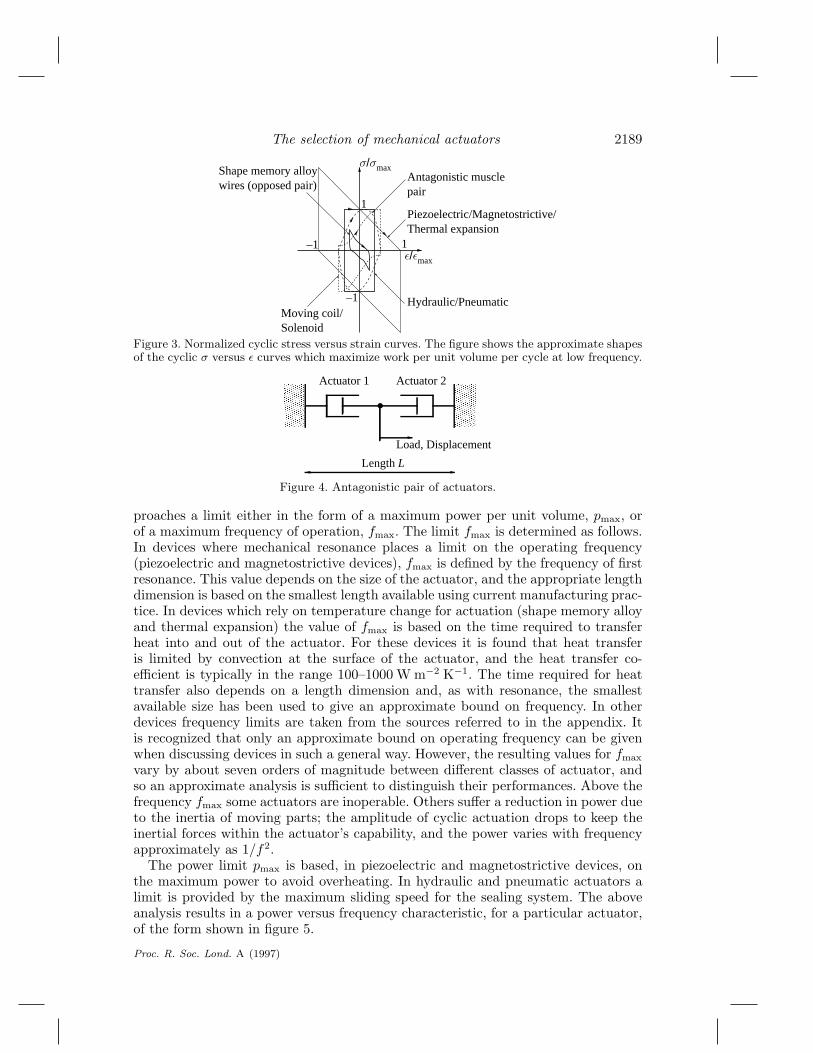
As with single-stroke actuation, the best performance is achieved by selectingthe actuator which has the maximum value of σmaxεmax, but now the selection isfrequency dependent. Figure 13 indicates that at frequencies below about 10 Hzshape memory alloys and hydraulic systems would be competitors. Above 10 Hzbut below about 300 Hz hydraulic systems would dominate. Above about 300 Hzmagnetostrictors may be used, in principle, for an actuator of minimum volume. Inpractice, minimum volume may not be the key design requirement. For example, thecost per unit volume of magnetostrictive materials is currently far higher than that ofelectromagnetic actuators such as solenoids and moving-coil transducers. The resultis that for a low cost shaker electromagnetic actuators are a practical alternative tomagnetostrictors for frequencies up to about 50 kHz.
Proc. R. Soc. Lond. A (1997)
2198 J. E. Huber, N. A. Fleck and M. F. Ashby
100
102
104
106
108
100
101
102
103
104
105
106
107
108
109
Frequency f [Hz]
Stre
ss-s
trai
n pr
oduc
t σε
[Jm
–3]
Low strain piezoelectric
High strain piezoelectric
Piezoelectric polymer
Thermal expansion (10K)
Thermal expansion (100K)
Magnetostrictor
Shape memory alloy
Moving coil transducer
Solenoid
Muscle
Pneumatic
Hydraulic
Figure 13. Stress–strain product σε versus frequency f for various actuators.
(c ) Selection of an actuator for vibration dampingCurrently, there is widespread research activity into the potential application of
cyclic actuators for the control of vibration in structures. We consider, as a case study,the selection of an actuator of minimum volume in order to damp a free vibration.Consider a simplified system consisting of an undamped mechanical oscillator withstiffness, s, vibrating with initial amplitude x0. An actuator of cross-sectional areaA and length L is to be attached as shown schematically in figure 14. The actuatoris intended to remove energy from the oscillating system, bringing it to rest in aprescribed number of cycles,N , whereN � 1. What is the minimum volume actuatorwhich can achieve this task?
The maximum stored elastic energy in the oscillator at amplitude x is E = 12sx
2.During each cycle the amount of energy which the actuator can remove depends on itscyclic stress versus strain characteristic, its volume and the amplitude of oscillation.Stress versus strain characteristics for actuators operating at maximum cyclic strainamplitude are shown in figure 3. An example of the stress versus strain characteristicwith varying strain amplitude is shown in figure 15.
In the nth cycle the oscillation has amplitude x and the actuator dissipates work ofmagnitude AL
∮σ(ε′; ε) dε′ where the strain amplitude of the current cycle ε ≡ x/L,
and σ(ε′; ε) is the stress corresponding to a strain ε′ in a cycle with strain amplitudeε. The dissipation per cycle is
ddn
(12sx
2) = −AL∮σ(ε′; ε) dε′, (4.3)
Proc. R. Soc. Lond. A (1997)

The selection of mechanical actuators 2199
Length L
Actuator
Section Area A
s
m 2x
Figure 14. An actuator used to damp a simple oscillator.
ε
σ
ε'
σ0
σ(ε'; ε)dε'
ε0
Figure 15. Cyclic stress versus strain characteristic for hydraulic and pneumatic actuators atvarying strain amplitude.
which, on substituting for x = εL and integrating, may be rearranged to the form∫ N
0
A
sLdn =
AN
sL=∫ ε0
0
(ε
/∮σ(ε′; ε) dε′
)dε. (4.4)
The right-hand side of equation 4.4 is a characteristic of the actuator and is a functionof the initial strain amplitude, ε0. It is convenient to express this in non-dimensionalform by introducing a damping coefficient Cd defined as
1Cd(ε0, σ0)
= 4σ0
ε0
∫ ε0
0
(ε
/∮σ(ε′; ε) dε′
)dε, (4.5)
where σ0 is the initial stress amplitude. The damping coefficient is in the range zeroto unity. Setting σ0 = σmax and ε0 equal to the maximum cyclic strain amplitudewhich can be achieved, gives maximum values for Cd. For hydraulic and pneumaticactuators the characteristic is similar to the one shown in figure 15, for which Cd
Proc. R. Soc. Lond. A (1997)

2200 J. E. Huber, N. A. Fleck and M. F. Ashby
equals unity. Piezoelectric, magnetostrictive and thermal expansion devices also haveCd ≈ 1. For shape memory alloy wires arranged as an opposed pair Cd is approxi-mately 0.2–0.3. The volume, V , of the actuator follows from equation 4.4:
V = AL =sx2
0
4NCdσmaxε0. (4.6)
Volume is minimized by selecting the actuator with the maximum value of the per-formance index Cdσmaxε0.
In a practical example, such as damping vibration at the engine mounting of a largeroad vehicle, constraints limit the choice of actuator. Space constraints would limitthe length L to about 0.1 m, so that a vibration of amplitude 1 mm would constrainthe selection to actuators capable of cyclic strain amplitude ε0 greater than 10−2.This limits the selection to shape memory alloy, hydraulic, pneumatic and solenoidactuators. A constraint on frequency, fmax > 100 Hz, would eliminate shape memoryalloys. Of the remaining choices, hydraulic actuators have by far the highest valueof Cdσmaxε0, resulting in the most compact design.
5. Conclusions
Performance characteristics which allow for comparison of a wide range of actu-ators have been developed. The penalty for such a broad comparison is a loss ofprecision—some aspects of the behaviour of individual actuators have had to be ne-glected, and it has been assumed that the properties of actuators are independentof frequency and scale. In practice, properties are frequency dependent, and scaleeffects, such as the dominance of frictional forces and surface energies in small de-vices, influence the choice of actuator. These aspects could be included in a moredetailed analysis. The benefit of the simplifications which have been made is anoverview which helps in selecting the most appropriate class of actuator for a givenmechanical task. In the early stages of the design of an active system, all actuatorsshould be considered; failure to do so may result in a missed opportunity. Graphicalpresentation of actuator characteristics helps to highlight where the opportunitieslie for new devices or substitute devices with improved performance. Selection of anactuator on the basis of a performance index gives a systematic, if approximate, wayof approaching design problems.
Performance characteristics have been estimated from manufacturers’ data andfrom simple physical models of performance limitation. It must be recognized thatsuch models contain assumptions about what is feasible both in design and in manu-facture. It would not be surprising if some of the limits given proved to be unattain-able in practical devices, or came to be surpassed through ingenious design.
To achieve the overview, actuators have been grouped into generic classes (‘hy-draulic’, ‘piezoelectric’ and so on); the data which appear in table 3 and are plottedon the charts characterize whole classes and are necessarily approximate. Higher pre-cision and more discriminating selection would be possible if the data for individualactuators within each class were stored and plotted. This method, particularly ifimplemented in software, could allow rapid identification of candidates for any givenactuation need.
The financial support of the EPSRC and of DRA Farnborough are gratefully acknowledged.
Proc. R. Soc. Lond. A (1997)

The selection of mechanical actuators 2201
Appendix A. Actuation systems
In the following sections a brief description is given of each of the classes of actu-ators and of the limitations to their performances.
(a) Piezoelectric actuatorsPiezoelectric materials strain when an external electric field e is applied. A variety
of phenomena exist which include piezoelectricity (ε ∝ e), electrostriction (ε ∝ e2)and ferroelectricity (ability to retain a remnant polarisation when e = 0). The phe-nomenon exhibited by a particular material depends on its structural symmetry andthe temperature relative to its Curie temperature Tc. Above Tc the stable structureis neither ferroelectric nor piezoelectric. There is an extensive literature which pro-vides an introduction to these materials (Xu 1991; Wang et al. 1987). For the presentpurposes, three groups of electrical materials are identified. Low strain piezoelectricssuch as Quartz (SiO2), Lithium Niobate (LiNbO3) and Lithium Tantalate (LiTaO3)are typically used as single crystals. They strain by up to about 3×10⁻⁵ upon appli-cation of an electric field. High strain piezoelectrics are dominated by lead zirconatetitanate alloys (PbZrxTi1−xO3, known as PZT) whose properties can be tailored byvarying the alloy composition, and by introducing dopants. Piezoelectric actuationstrains of up to about 2 × 10⁻⁴ are feasible. The efficiency of PZT ceramics is rel-atively low by comparison with the low strain piezoelectrics. Piezoelectric polymerssuch as polyvinylidene fluoride ((CH2CF2-)n, known as PVDF) and related polymerscan strain by up to about 1× 10⁻³; their properties can be modified by directionalforming and they possess high formability. Their modulus (2–10 GPa) is about twoorders of magnitude less than that of piezoelectric ceramics.
In all of the piezoelectric-type materials the maximum strain, εmax, is limited bythe tolerable level of electric field. An electric field of strength above the coercive fieldresults in dramatic changes in properties such as the reversal of polarization in ferro-electric materials. In practice, field levels are often limited to a lower value to avoidmechanical and electrical fatigue. An actuation stress is generated by constrainingthe material from changing shape. In piezoelectric materials this can be modelledas linear elastic behaviour giving rise to a maximum actuation stress σmax = Eεmaxwhen the actuator is fully constrained. The maximum operating frequency is limitedby mechanical resonance; fmax = c/2L, where c ≈
√E/ρ is the mechanical wave
speed and L is the length of the actuator. This limit is size dependent and so theabsolute maximum operating frequency is limited by the ability to manufacture ac-tuators of small size. A practical limit of 10−4 m is used here. The maximum powerper unit volume pmax is limited by heat dissipation, and the need to maintain thedevice at a tolerable temperature (typically well below the Curie temperature toavoid rapid fatigue). The recommended power limits given by suppliers provide auseful guide. In the absence of this information, an approximate power limit can bederived based on the efficiency, and using air convection to remove heat from thedevice. Performance characteristics have been compiled from the literature of ma-terial suppliers (Morgan Matroc Ltd, Piezo Kinetics Inc., Channel Industries Inc.,Piezo Systems Inc., Valpey-Fisher Corporation), and from other sources (Ikeda 1990;Wang et al. 1987; Moulson & Herbert 1990).
(b) Shape memory alloy actuatorsThe mechanism of actuation in shape memory alloys is a temperature-induced
phase change which produces a significant shear strain on heating above the trans-
Proc. R. Soc. Lond. A (1997)

2202 J. E. Huber, N. A. Fleck and M. F. Ashby
formation temperature. This effect has given rise to a variety of applications (Duerig1990). High values of σmax (up to about 7×10⁸ N m−2) and εmax (up to about 7×10⁻²)can be achieved in nickel–titanium alloys of approximately equiatomic composition.Other shape memory alloys exist. In the copper–aluminium alloy system several al-loys exhibit shape memory but the performance is relatively poor by comparison withNi–Ti alloys. Iron–manganese–silicon alloys provide a potential low cost competitor,best suited to single-stroke operation because of their high hysteresis. For actuation,shape memory alloys are often used in the form of a wire or foil which reduces inlength when heated, and can be returned to its original length by cooling and thenstretching. Heating can be achieved by electrical resistance in shape memory alloywires, with the resulting tensile forces providing a single acting actuator. For cyclicoperation, a mechanism is required to reset the actuator. This imposes limitationson σmax and εmax. In the present analysis, the resetting mechanism is assumed tobe a second shape memory alloy actuator—alternative resetting mechanisms such assprings or weights are also common. In cyclic applications, the frequency of opera-tion and the power output are limited by heat transfer, and the temperature changerequired for actuation. A temperature change of 15–30 K is usually required to ac-tivate shape memory alloys. However, to achieve a high actuation stress, a largertemperature change (about 100 K) is preferable. Electrical resistance heating can beachieved rapidly; cooling is the main limitation on operating frequency. The maxi-mum frequency is dependent on the relevant length scale for cooling, which can be assmall as about 0.5×10⁻⁴ m, based on thinnest readily available shape memory alloywires. Using this value for the radius of a shape memory alloy wire and cooling byconvection with surface heat transfer coefficient in the range 100–1000 W m−2 K−1
gives rise to a maximum operating frequency in the range 0.02–7 Hz. Performancedata for shape memory alloys have been compiled from the literature of materialsuppliers (Advanced Materials and Technologies n.v., Thomas Bolton Ltd, DynalloyInc.), and from other sources (Smithells 1992; Duerig 1990).
(c) Magnetostrictive actuatorsMagnetostrictive materials produce an actuation strain under the influence of an
applied magnetic field, caused by the reorientation of magnetic domains. Althoughmany materials display this phenomenon, the effect is generally small except iniron-lanthanide compounds. The most commonly used magnetostrictor is ‘Terfenol’(Tb0.3Dy0.7Fe1.9). The actuation strain in magnetostrictors is limited by magneticsaturation, and this provides a suitable upper limit εmax. The other aspects of magne-tostrictors’ performance are analogous to those of piezoelectrics and the same methodhas been used to determine the maximum operating frequency and the maximumpower per unit volume. Data for magnetostrictors are taken from McCurrie (1994)and Wohlfarth (1980).
(d) Thermal expansion actuatorsThermal expansion gives rise to a shape change which can be used for actuation,
and is convenient when the control signal is available in the form of a temperature,such as in thermostatic applications. The actuation strain equals α∆T , where α is thecoefficient of thermal expansion and ∆T is the temperature change. The maximumvalue of the actuation strain, εmax is limited by the maximum allowable temperaturechange which depends upon the specific application. Temperature changes in therange 10–100 K are typical. The choice of material for an actuator based on thermal
Proc. R. Soc. Lond. A (1997)
The selection of mechanical actuators 2203
expansion depends on the requirements of the actuator. When a large actuationstrain is desired for a given temperature change, α is to be maximized and polymersperform well. Note that the actuation stress is achieved by constraining the materialfrom changing shape. Thus a high value of σmax is achieved by selecting a materialwhich maximizes Eα, provided that σmax = Eα∆T does not exceed the failurestress. If a high volumetric stroke work is required the selection criterion becomesEα2. Engineering alloys perform well in these last two cases. Operating frequenciesare limited by the rate of heat transfer into and out of the device. Estimates forthe frequency and power limitations for thermal expansion actuators can be carriedout in the same manner as described above for shape memory alloys. The criticaldimension for cooling is taken to be 10−4 m, consistent with the minimum thicknessesof readily available bimetallic strips (Kanthal AB).
(e) Hydraulic and pneumatic actuatorsHydraulic and pneumatic actuators provide force and displacement via the flow of
a pressurized fluid. The actuation strain is limited only by the design of the actuator.A reasonable upper limit is εmax ≈ 1. The maximum actuation stress, σmax, is limitedby the pressure of the working fluid. In hydraulics the difficulty of high-pressure con-tainment begins to outweigh high pressure advantages at about 40–45 MPa (Brunell1979) but higher pressures are feasible; proprietary systems have actuation stressesup to about 70 MPa (Enerpac Ltd). In pneumatics, the compressibility of the workingfluid gives rise to both safety and energy efficiency limitations at pressures in excessof about 1 MPa. The main limitation on volumetric power is set by the maximumsliding speeds vmax which can be tolerated by the seals, as follows. The actuator cando work 4Ccσmaxεmax per unit volume in a single cycle during cyclic operation. Themaximum power per unit volume is then pmax = 4Ccσmaxεmaxvmax/L where L is theinitial length of the actuator. A low value of L gives rise to a high value of pmax andso reducing the length of a hydraulic or pneumatic actuator raises pmax. Lengths ona scale smaller than about 10−1 m become impractical and vmax is limited to about0.5 m s−1 (Brunell 1979). This limits pmax to 3 × 10⁸ W m−3 for hydraulics and to5× 106 W m−3 for pneumatics.
(f) Electromagnetic actuatorsThree forms of electromagnetic machines are commonly used as actuators:
solenoids, moving coil transducers and motors. Solenoids consist of an electromag-netic coil and a high permeability rod; when energized the solenoid pulls on therod via its magnetic field. Commercially available solenoids have a maximum ac-tuation stress σmax of about 1 × 10⁵ N m−2 and actuation strains of up to about0.4. Performance data for the most common types of solenoid can be found in thedata sheets of component suppliers. In cyclic operation it is necessary to provide aresetting mechanism, which, in the present analysis, is taken to be a second solenoid.Resetting mechanisms such as springs and weights could also be used. Solenoids areusually limited to low frequencies (less than 100 Hz) because of the inertia of themoving armature. Frequencies of up to 50 kHz are achievable in moving coil trans-ducers since the moving part is a low-inertia current-carrying coil. Details of a widevariety of designs for moving coil transducers are available in the literature (Wavre& Thouvenin 1995; Borwick 1988; Greenwood 1965). Motors, which can be arrangedto give (in principle) infinite displacements, are not considered here; an introductionto linear motors can be found in the references (Nasar & Boldea 1976).
Proc. R. Soc. Lond. A (1997)

2204 J. E. Huber, N. A. Fleck and M. F. Ashby
(g) Natural actuatorsThe means of actuation employed by living organisms for locomotion and shape
change provide a useful comparison with artificial machines. Actuation in animalsis carried out predominantly using muscle. Muscle strains by thick fibres of myosinclimbing along thin fibres of actin. The mechanism relies upon the ability of thecross bridges at the heads of the myosin molecules to change shape, detach and re-attach further along the actin fibres. The chemical energy which drives this action isreleased from adenosine triphosphate (ATP). Performance characteristics have beenestimated on the basis of data in the literature of muscle physiology (Woledge 1985;McMahon 1984). Typically, muscle can achieve nominal strains of up to about 0.75and stresses of about 0.3 MPa.
The source of actuation which allows plants to achieve rapid active shape changes(such as stamens which bend over to daub visiting insects with pollen) is different.This usually relies on stored elastic energy which is built up gradually, in advanceof action (Simons 1992). Plants can control the concentration of positively chargedions such as K+ in their cell sap by using ion pumps which transport ions acrosscell membranes. Osmosis drives water up the K+ concentration gradient, resultingin a turgor pressure within plant cells of about 1 MPa and a volumetric strain ofup to 0.50 (Wilkins 1984). Turgor pressure can be made to act against an elasticstructural member which deforms and then returns rapidly to its original shape whenthe pressure is released. The resulting single stroke actuator can operate rapidly,but even the most rapid plant gyration requires a reset time of 90 s (Hart 1990).Consequently the power in cyclic operation is low.
(h) Actuators based on material state changesVarious actuation systems based on expansion or contraction during phase changes
in materials are possible. The example of shape memory alloys has already beendiscussed. A further example is the wax actuator, which is based on the expansionof wax during melting, and is used in thermostatic devices. Wax-based actuators canachieve strains of up to about 40% and actuation stresses of about 1 MPa (Duerig1990). The liquid–solid phase change in water gives rise to actuation which is knownfor its damaging effect in structures, termed ‘frost-heave’.
ReferencesAdvanced Materials and Technologies n.v. Properties of shape memory alloys. Industrieweg 43
B-3540 Herk-de-Stad, Belgium.Ashby, M. F. 1989 On the engineering properties of materials. Acta Metall. 37, 1273–1293.Ashby, M. F. 1992 Materials selection in mechanical design. Oxford: Pergamon.Ashby, M. F. & Cebon, D. 1993 Materials selection in mechanical design. J. Physique 3, 1–9.Barrett, R. 1992 Active plate and wing research using EDAP elements. Smart Mater. Struct. 1,
214–226.Bidaux, J.-E., Yu, W. J., Gotthardt, R. & Manson, J.-A. 1994 Modelling of the martensitic
transformation in shape memory alloy composites. In Proc. 3rd Eur. Symp. on MartensiticTransformations, Barcelona, 14–16/9/1994.
Borwick, J. 1988 Loudspeaker and headphone handbook. London: Butterworth.Bothwell, C. M., Chandra, R. & Chopra, I. 1995 Torsional actuation with extension torsion
composite coupling and a magnetostrictive actuator. AIAA Jl 33, 723–729.Brunell, R. 1979 Hydraulic and pneumatic cylinders. Trade & Technical.
Proc. R. Soc. Lond. A (1997)

The selection of mechanical actuators 2205
Channel Industries, Inc. Piezoelectric ceramic. 839 Ward Drive, Santa Barbara, CA 93111, USA.Crawley, E. F. & de Luis, J. 1987 Use of piezoelectric actuators as elements of intelligent struc-
tures. AIAA Jl 25, 1373–1385.Duerig, T. W. 1990 Engineering aspects of shape memory alloys. London: Butterworth–
Heinemann.Dynalloy, Inc. Flexinol Actuator Wires. 18662 MacArthur Blvd., Suite103, Irvine, CA 92715,
USA.Enerpac Ltd. High force hydraulic tools 13000 W. Silver Spring Drive, Butler, Wisconsin 53007,
USA.Furnya, Y. & Shimada, H. 1991 Shape memory actuators for robotic applications. Mater. Design
12, 21–28.Greenwood, D. C. 1965 Manual of electromechanical devices. New York: McGraw-Hill.Hart, J. W. 1990 Plant tropisms and other growth movements. London: Unwin Hyman.Ikeda, T. 1990 Fundamentals of piezoelectricity. Oxford University Press.Kanthal AB Thermostatic Bimetal. Strip and Bimetal, Box 518, S-734 27 Hallstahammar, Swe-
den.McCurrie, R. A. 1994 Ferromagnetic materials: structure and properties. London: Academic.McDonald Schetky, L. 1991 Shape memory alloy applications in space systems. Mater. Design
12, 29–32.McMahon, T. A. 1984 Muscles, reflexes and locomotion. Princeton University Press.Morgan Matroc Ltd Piezoelectric ceramics. Vauxhall Industrial Estate, Ruabon, Wrexham,
Clwyd LL14 6HY, UK.Moulson, A. J. & Herbert, J. M. 1990 Electroceramics: materials, properties, applications. Lon-
don: Chapman and Hall.Nasar, S. A. & Boldea, I. 1976 Linear motion electric machines. New York: Wiley.Piezo Kinetics, Inc. Piezoceramics application notes. P.O. Box 756, Pine Street and Mill Road,
Bellefonte, PA 16823, USA.Piezo Systems, Inc. Product Catalog. 186 Massachusetts Ave., Cambridge, MA 02139, USA.Shaw, J. A. & Kyriakides, S. 1995 Thermomechanical aspects of NiTi. J. Mech. Phys. Solids
43, 1243–1281.Shen, M.-H. H. 1994 Analysis of beams containing piezoelectric sensors and actuators. Smart
Mater. Struct. 3, 439–447.Simons, P. 1992 The action plant: movement and nervous behaviour in plants. Oxford: Blackwell.Smithells, C. J. 1992 Smithells metals reference book, 7th edn. London: Butterworth-Heinemann.Thomas Bolton Ltd Data sheet MJB/SMA/601/88. P.O. Box 1, Froghall, Stoke-on-Trent, Staffs.
ST10 2HF, UK.Valpey–Fisher Corporation Piezoelectric transducer crystals. 75 South Street Hopkinton, MA
01748, USA.Venison, G. S. 1986 A practical look at shape memory alloys’ potential as a thermal actuator.
Mater. Design 7, 143–146.Wang, T. T., Herbert, J. M. & Glass, A. M. 1987 The Applications of ferroelectric polymers.
Blackie.Wavre, N. & Thouvenin, X. 1995 Voice-coil actuators in space. In Proc 6th European Space
Mechanisms & Tribology Symp.Wilkins, M. B. 1984 Advanced plant physiology. London: Pitman.Wohlfarth, E. P. 1980 Ferromagnetic materials: a handbook on the properties of magnetically
ordered substances. Oxford: North-Holland.Woledge, R. C. 1985 Energetic aspects of muscle contraction, ch. 1, 2. London: Academic.Xu, Y. 1991 Ferroelectric materials and their applications. Amsterdam: North Holland.
Received 11 September 1996; revised 3 March 1997; accepted 10 April 1997
Proc. R. Soc. Lond. A (1997)