THE REPUBLIC OF LIBERIA Bureau of Maritime Affairs · of Maritime Affairs ... Lifeboat launching...
65
Office of Deputy Commissioner of Maritime Affairs 13 August 2009 MARINE OPERATIONS NOTE 7/2009 Subject: Paris and Tokyo MOU Concentrated Inspection Campaign on Lifeboat Launching Arrangements Ref: (a) (b) (c) SOLAS Chapter III MSC.1/Circ.1205 MSC.1/Circ.1206 Rev.1 To: Shipowners/Operators and Masters, The 43 Maritime Authorities of the Tokyo and Paris MOUs on Port State Control announced that they will begin a joint Concentrated Inspection Campaign (CIC) to ensure compliance with SOLAS Chapter III-Lifesaving Appliances and Arrangements with regard to lifeboat launching arrangements. This campaign will be held for three months starting 1 September and ending 30 November 2009. During every port State control inspection Port State Control Officers (PSCOs) within the Paris and Tokyo MOU regions will verify the lifeboat launching arrangements, maintenance records and other applicable documentation for compliance. PSCOs will use the enclosed questionnaire listing 20 selected items to verify critical areas for the safety of lifeboat launching arrangements, including some related to documentation, equipment and seafarer familiarization. The 43 member states of the Paris and Tokyo MOU are as follows: Paris MOU: Belgium, Bulgaria, Canada, Croatia, Cyprus, Denmark, Estonia, Finland, France, Germany, Greece, Iceland, Ireland, Italy, Latvia, Lithuania, Malta, Netherlands, Norway, Poland, Portugal, Romania, Russian Federation, Slovenia, Spain, Sweden, and United Kingdom. Tokyo MOU: Australia, Canada, Chile, China, Fiji, Hong Kong, Indonesia, Japan, Republic of Korea, Malaysia, New Zealand, Papua New Guinea, Philippines, Russian Federation, Singapore, Thailand, Vanuatu, and Vietnam. Recommended Action: We recommend Shipowners/Operators inform their Master’s of the CIC through copy of this Note and to prepare for detailed lifeboat inspections when calling on ports in any of the above countries. We recommend Master’s use the enclosed questionnaire in preparing for inspections to ensure all relevant areas are satisfactorily addressed prior to entry into these ports. We kindly request a copy of the completed THE REPUBLIC OF LIBERIA Bureau of Maritime Affairs 8619 Westwood Ctr. Dr. Suite 300 Vienna VA. USA 22182 Telephone: +1 703 790 3434 Fax: +1 703 790 5655 Email: [email protected]
Transcript of THE REPUBLIC OF LIBERIA Bureau of Maritime Affairs · of Maritime Affairs ... Lifeboat launching...
Office of Deputy Commissioner of Maritime Affairs
13 August 2009
MARINE OPERATIONS NOTE 7/2009 Subject: Paris and Tokyo MOU Concentrated Inspection Campaign on Lifeboat
Launching Arrangements Ref: (a) (b) (c)
SOLAS Chapter III MSC.1/Circ.1205 MSC.1/Circ.1206 Rev.1
To: Shipowners/Operators and Masters, The 43 Maritime Authorities of the Tokyo and Paris MOUs on Port State Control announced that they will begin a joint Concentrated Inspection Campaign (CIC) to ensure compliance with SOLAS Chapter III-Lifesaving Appliances and Arrangements with regard to lifeboat launching arrangements. This campaign will be held for three months starting 1 September and ending 30 November 2009. During every port State control inspection Port State Control Officers (PSCOs) within the Paris and Tokyo MOU regions will verify the lifeboat launching arrangements, maintenance records and other applicable documentation for compliance. PSCOs will use the enclosed questionnaire listing 20 selected items to verify critical areas for the safety of lifeboat launching arrangements, including some related to documentation, equipment and seafarer familiarization. The 43 member states of the Paris and Tokyo MOU are as follows:
Paris MOU: Belgium, Bulgaria, Canada, Croatia, Cyprus, Denmark, Estonia, Finland, France, Germany, Greece, Iceland, Ireland, Italy, Latvia, Lithuania, Malta, Netherlands, Norway, Poland, Portugal, Romania, Russian Federation, Slovenia, Spain, Sweden, and United Kingdom.
Tokyo MOU: Australia, Canada, Chile, China, Fiji, Hong Kong, Indonesia, Japan, Republic of Korea, Malaysia, New Zealand, Papua New Guinea, Philippines, Russian Federation, Singapore, Thailand, Vanuatu, and Vietnam.
Recommended Action: We recommend Shipowners/Operators inform their Master’s of the CIC through copy of this Note and to prepare for detailed lifeboat inspections when calling on ports in any of the above countries. We recommend Master’s use the enclosed questionnaire in preparing for inspections to ensure all relevant areas are satisfactorily addressed prior to entry into these ports. We kindly request a copy of the completed
THE REPUBLIC OF LIBERIA Bureau of Maritime Affairs
8619 Westwood Ctr. Dr. Suite 300 Vienna VA. USA 22182 Telephone: +1 703 790 3434 Fax: +1 703 790 5655 Email: [email protected]
questionnaire is sent to the Administration at: [email protected], for information on the manufacturer and model of on-load release gear for an internal lifeboat casualty study. In addition to the using the questionnaire, we also recommend Masters review SOLAS III/16 - Survival Craft Launching and Recovery Arrangements and ensure that appropriate crew members are thoroughly trained on the lifeboat launching arrangements. Particular attention should be paid to the correct operation of lifeboat on-load release mechanisms when applicable. The following should also be verified as completed and recorded:
1. The monthly abandon ship drill (SOLAS III/ 19.3.2), 2. Lifeboat launching every three months (SOLAS III/ 19.3.3), 3. On board training (SOLAS III/ 19.4), 4. Record keeping (SOLAS III 19.5). 5. Maintenance of falls (SOLAS III/20.4), 6. The weekly and monthly inspections (SOLAS III/20.6 and 20.7), 7. Periodic servicing of launching appliances and on-load release gear (SOLAS
III/20.11. See also MSC.1/Circ.1206 Rev.1, 8. Training Manual (SOLAS III/35.3), 9. Instruction for on board maintenance (SOLAS III/36), and 10. Muster list and emergency instructions (SOLAS III/37).
A copy of the following IMO documents, prepared in response to lifeboat accidents and referenced in the MOU questionnaire, are also provided for use by the Master and crew: MSC.1/Circ.1205 - Guidelines for Developing Operation and Maintenance Manuals for Lifeboat Systems MSC.1/Circ.1206 Rev.1 - Measures to Prevent Accidents with Lifeboats Reporting defective equipment: When a piece of required equipment is suddenly found defective, damaged, or there is a justifiable reason for not launching the lifeboat every three months, the vessel operator should contact the Administration immediately. When appropriate we may issue a dispensation before the vessel reaches port, allowing time for necessary corrective action. A dispensation may avoid a detention for defective equipment or for a required procedure which could not be followed. For technical dispensations, please email [email protected]. In the event of a detention, contact us immediately so we can help to resolve the issues as quickly as possible. To report a detention or if you have any questions, please contact Timothy Keegan, +1-703251-2409, or Sean Brett, +1-703-251-2434, or email [email protected]. If it is an emergency after business hours or during the weekend contact the duty officer at +1-703-963-6216. To assist the duty officer with developing a proper response, send an email to [email protected] describing the issues that need to be addressed. Enclosure: MOU CIC Checklist
*********
- PARIS MOU ON PORT STATE CONTROL
1
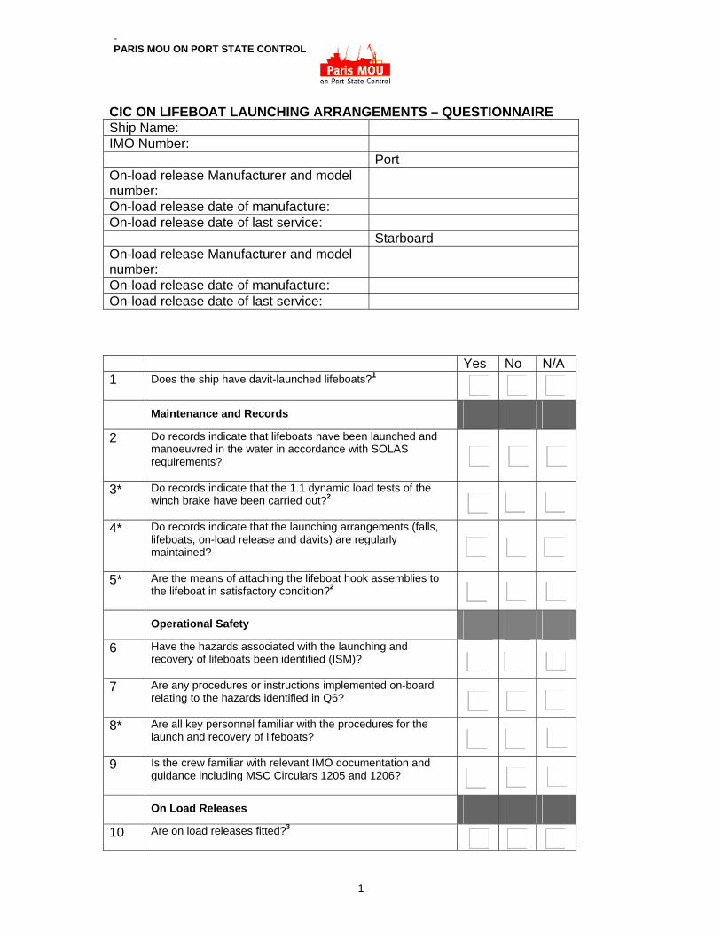
CIC ON LIFEBOAT LAUNCHING ARRANGEMENTS – QUESTIONNAIRE Ship Name: IMO Number: Port On-load release Manufacturer and model number:
On-load release date of manufacture: On-load release date of last service: Starboard On-load release Manufacturer and model number:
On-load release date of manufacture: On-load release date of last service:
Yes No N/A 1 Does the ship have davit-launched lifeboats?1
Maintenance and Records
2 Do records indicate that lifeboats have been launched and manoeuvred in the water in accordance with SOLAS requirements?
3* Do records indicate that the 1.1 dynamic load tests of the winch brake have been carried out?2
4* Do records indicate that the launching arrangements (falls, lifeboats, on-load release and davits) are regularly maintained?
5* Are the means of attaching the lifeboat hook assemblies to the lifeboat in satisfactory condition?2
Operational Safety 6 Have the hazards associated with the launching and
recovery of lifeboats been identified (ISM)?
7 Are any procedures or instructions implemented on-board relating to the hazards identified in Q6?
8* Are all key personnel familiar with the procedures for the launch and recovery of lifeboats?
9 Is the crew familiar with relevant IMO documentation and guidance including MSC Circulars 1205 and 1206?
On Load Releases 10 Are on load releases fitted?3
2
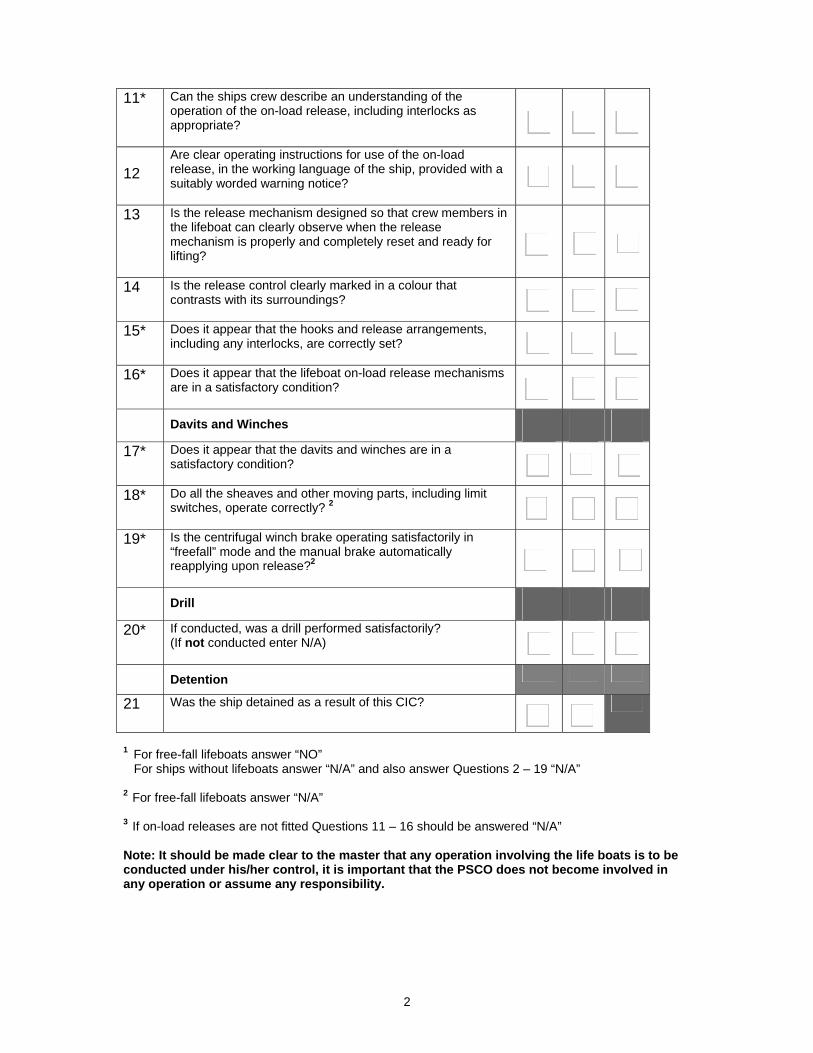
11* Can the ships crew describe an understanding of the operation of the on-load release, including interlocks as appropriate?
12
Are clear operating instructions for use of the on-load release, in the working language of the ship, provided with a suitably worded warning notice?
13 Is the release mechanism designed so that crew members in the lifeboat can clearly observe when the release mechanism is properly and completely reset and ready for lifting?
14 Is the release control clearly marked in a colour that contrasts with its surroundings?
15* Does it appear that the hooks and release arrangements, including any interlocks, are correctly set?
16* Does it appear that the lifeboat on-load release mechanisms are in a satisfactory condition?
Davits and Winches 17* Does it appear that the davits and winches are in a
satisfactory condition?
18* Do all the sheaves and other moving parts, including limit switches, operate correctly? 2
19* Is the centrifugal winch brake operating satisfactorily in “freefall” mode and the manual brake automatically reapplying upon release?2
Drill 20* If conducted, was a drill performed satisfactorily?
(If not conducted enter N/A)
Detention
21 Was the ship detained as a result of this CIC?
1 For free-fall lifeboats answer “NO” For ships without lifeboats answer “N/A” and also answer Questions 2 – 19 “N/A” 2 For free-fall lifeboats answer “N/A” 3 If on-load releases are not fitted Questions 11 – 16 should be answered “N/A” Note: It should be made clear to the master that any operation involving the life boats is to be conducted under his/her control, it is important that the PSCO does not become involved in any operation or assume any responsibility.
I:\CIRC\MSC\01\1205.doc
INTERNATIONAL MARITIME ORGANIZATION 4 ALBERT EMBANKMENT LONDON SE1 7SR Telephone: 020 7587 3152 Fax: 020 7587 3210
IMO
E
Ref. T4/4.01 MSC.1/Circ.1205 26 May 2006
GUIDELINES FOR DEVELOPING OPERATION AND MAINTENANCE MANUALS FOR LIFEBOAT SYSTEMS
1 The Maritime Safety Committee, at its eighty-first session (10 to 19 May 2006), taking into account the number of casualties with lifeboat systems, further recognizing the need to improve manuals for operation and maintenance of lifeboat systems, and having considered proposals by the Sub-Committee on Fire Protection at its fiftieth session, approved the Guidelines for developing operation and maintenance manuals for lifeboat systems, as set out in the annex. 2 Member Governments are invited to bring the annexed Guidelines to the attention of all parties concerned with their application, as appropriate.
***

MSC.1/Circ.1205
I:\CIRC\MSC\01\1205.doc
ANNEX
GUIDELINES FOR DEVELOPING OPERATION AND MAINTENANCE MANUALS FOR LIFEBOAT SYSTEMS
1 Scope and purpose of the guidelines Seafarers often change ships and sometimes are not familiar with the lifeboats on their ships. Casualties with lifeboat systems are often caused by poor understanding of the lifeboat systems, especially release gear systems. User-friendliness of manuals for lifeboat systems is, therefore, important to help prevent casualties. The purpose of these guidelines is to encourage development of user-friendly manuals for operation and maintenance of lifeboat systems including launching appliances. These manuals should be easy to understand. The guidelines demonstrate the appropriate level of detail and use of illustrations in explaining the safe use of critical systems. Manufacturers of lifeboats and launching/recovery appliances are invited to make manuals easy to understand, taking into account these guidelines. The use of video materials in conjunction with printed manuals can be an effective tool for mariners who may not be inclined to read a manual. These guidelines are not applicable to the emergency instructions required by SOLAS regulation III/8, operating instructions such as posters and signs required by SOLAS regulation III/9 or other brief instructions for operation of lifeboats. These guidelines are for manuals to be carried on ships for use by seafarers, and accordingly the section on weekly and monthly inspection and maintenance does not refer to detailed maintenance/repair work. Detailed maintenance/repair work should be conducted by the manufacturer’s representative or a person appropriately trained and certified by the manufacturer for the work in accordance with MSC.1/Circ.1206. 2 Collaboration of manufacturers of the lifeboat and the launching appliance A manual for a lifeboat system including launching appliance should be developed with the collaboration of manufacturers of the lifeboat and the launching appliance and preferably be a single document. As a minimum, the use of different words for the same gear/parts of the lifeboat system should be eliminated by the collaboration of manufacturers of the lifeboat and the launching appliance to prevent misunderstanding by seafarers. Hereafter, these guidelines assume a manual for a lifeboat system includes the launching appliance as a minimum, but separate lifeboat, release gear, and launching appliance manuals may be effective if adequately co-ordinated and using the same style of presentation per these guidelines. 3 Contents of a manual for a lifeboat system 3.1 Items to be included An operation and maintenance manual for a lifeboat system should include, as a minimum, the following items:
.1 overview and specification of the lifeboat system; .2 explanation of the structure and working principle of the major parts of the lifeboat
system including release gear systems;
MSC.1/Circ.1205 ANNEX Page 2
I:\CIRC\MSC\01\1205.doc
.3 operation of the lifeboat system; and .4 routine inspection and maintenance of the lifeboat system.
3.2 Organization, description and layout of manual 3.2.1 Outline It is recommended that a manual for a lifeboat system be developed with the following major divisions:
1 General description of the whole lifeboat system. 2 Method of checking proper closure of release hooks. 3 Launching operation. 4 Recovery operation. 5 On-load/off-load release gear. 6 Inspection and maintenance.
3.2.2 Explanation of major components and their function The structure and working principle of the lifeboat’s major components, in particular the on-load/off-load release gear, should be explained using figures and preferably three-dimensional perspectives. In addition, the operation of the release gear should be described sequentially, using short phrases written in the active voice. 3.2.3 Operation of lifeboat system including release gear systems The operation of the lifeboat system should be described using the following elements:
.1 flow of the operation should be explained; .2 detail of operation should be explained with figures. Operation and relevant
movement of the parts of the release gear should be described with illustrations/photos, preferably using annotations and arrows to show direction of movement; and
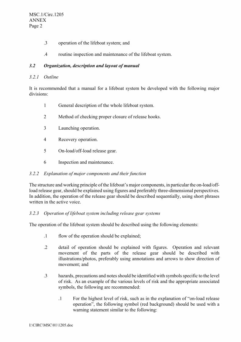
.3 hazards, precautions and notes should be identified with symbols specific to the level
of risk. As an example of the various levels of risk and the appropriate associated symbols, the following are recommended:
.1 For the highest level of risk, such as in the explanation of “on-load release
operation”, the following symbol (red background) should be used with a warning statement similar to the following:
MSC.1/Circ.1205 ANNEX
Page 3
I:\CIRC\MSC\01\1205.doc
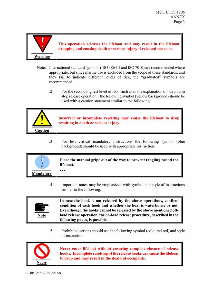
Warning
This operation releases the lifeboat and may result in the lifeboat dropping and causing death or serious injury if released too soon.
Note: International standard symbols (ISO 3864-1 and ISO 7010) are recommended where
appropriate, but since marine use is excluded from the scope of these standards, and they fail to indicate different levels of risk, the “graduated” symbols are recommended.
.2 For the second highest level of risk, such as in the explanation of “davit arm
stop release operation”, the following symbol (yellow background) should be used with a caution statement similar to the following:
Caution
Incorrect or incomplete resetting may cause the lifeboat to drop resulting in death or serious injury.
.3 For less critical mandatory instructions the following symbol (blue
background) should be used with appropriate instruction:
Mandatory
Place the manual gripe out of the way to prevent tangling round the lifeboat. . . .
.4 Important notes may be emphasized with symbol and style of instructions
similar to the following:
Note
In case the hook is not released by the above operations, confirm condition of each hook and whether the boat is waterborne or not. Even though the hooks cannot be released by the above mentioned off-load release operation, the on-load release procedure, described in the following pages, is possible.
.5 Prohibited actions should use the following symbol (coloured red) and style
of instruction:
Never
Never enter lifeboat without ensuring complete closure of release hooks. Incomplete resetting of the release hooks can cause the lifeboat to drop and may result in the death of occupants.
MSC.1/Circ.1205 ANNEX Page 4
I:\CIRC\MSC\01\1205.doc
3.2.4 Inspection and maintenance The items for weekly and monthly inspection/maintenance and other inspection/maintenance should each be explained separately. 4 Improvement of user-friendliness of a manual 4.1 Use of figures/photographs Figures, preferably coloured, or photographs should be used as far as practicable to make manuals easy to understand. 4.2 Use of standard wording The following standard wording should be used to explain lifeboat systems where provided, and for each of the applicable items illustrations should be provided to show the items and their location in the lifeboat or on the ship. The use of alternative terms for variety should be avoided, except to further define or clarify a term so that the reader never has to guess what item or system is being discussed.
.1 Davit/winch:
.1 Auto releasing gripe
.2 Davit arm
.3 Davit arm stop
.4 Davit remote control wire handle
.5 Frame
.6 Maintenance (hanging off) pennant attachment points, if provided
.7 Manual gripe, if provided
.8 Remote control wire
.9 Winch manual brake safety pin
.10 Winch hand crank handle
.11 Winch centrifugal or lowering brake
.12 Winch hand brake or stop brake lever .2 Freefall:
.1 Roller or sliding pad
.2 Sea lashing rope
.3 Emergency release device .3 Release gear:
.1 Hook control cable
.2 Hook retainer (lock piece)
.3 Hydrostatic interlock
.4 Hydrostatic interlock lever, if provided
.5 Interlock (“mechanical protection” of on-load release)
.6 Maintenance (hanging off) pennant attachment points, if provided
.7 On-load release
.8 Release handle
MSC.1/Circ.1205 ANNEX
Page 5
I:\CIRC\MSC\01\1205.doc
.9 Release handle “closed (locked)” and “open” positions
.10 Release handle “safety pin”
.11 Release hook (hook unit) (fore and aft hooks)
.12 Reset lever, if provided
.13 Safety latch (keeper) .4 Suspension:
.1 Foul weather recovery strops
.2 Suspension block
.3 Suspension link (lifting ring) .5 “Officer in charge” of lifeboat
5 Example of an operation and maintenance manual for a lifeboat system An example of an operation and maintenance manual for a fire-protected lifeboat system is attached in the following pages just for reference. It demonstrates the suitable level of detail that should be expected for manuals. It should be noted that lifeboat systems are different from each other and some specifications in the example manual are not applicable to lifeboat systems of other types. The example attached at appendix is a model manual which is recommended as an example for developing specific manuals for lifeboat systems launched by falls, but the same general principles should be used for manuals for freefall lifeboat systems.
* * *
MSC.1/Circ.1205 ANNEX Page 6
I:\CIRC\MSC\01\1205.doc
APPENDIX
EXAMPLE OPERATION AND MAINTENANCE MANUAL FOR A LIFEBOAT SYSTEM*
Table of contents 1 General 2 Method of checking proper closure of release hooks 3 Launching operation
3.1 Preparation before launching 3.2 Setting painter 3.3 Release of safety pin for winch hand brake lever 3.4 Release of davit arm stop 3.5 Boarding the lifeboat 3.6 Launching procedure 3.7 Release gear operation 3.8 Painter release and lifeboat operation
4 Recovery operation
4.1 Resetting procedure of release hook 4.2 Recovery procedure 4.3 Stowage procedure
5 On-load/off-load release gear system
5.1 General 5.2 Fore and aft hook units 5.3 Release handle unit 5.4 Hydrostatic interlock unit
6 Inspection and maintenance
6.1 General precautions 6.2 Inspection and maintenance of lifeboat and release gear system 6.3 Inspection and maintenance of launching appliances (davits and winches)
* Of a lifeboat being launched using falls and a winch, hereinafter referred to as a lifeboat.
MSC.1/Circ.1205 ANNEX
Page 7
I:\CIRC\MSC\01\1205.doc
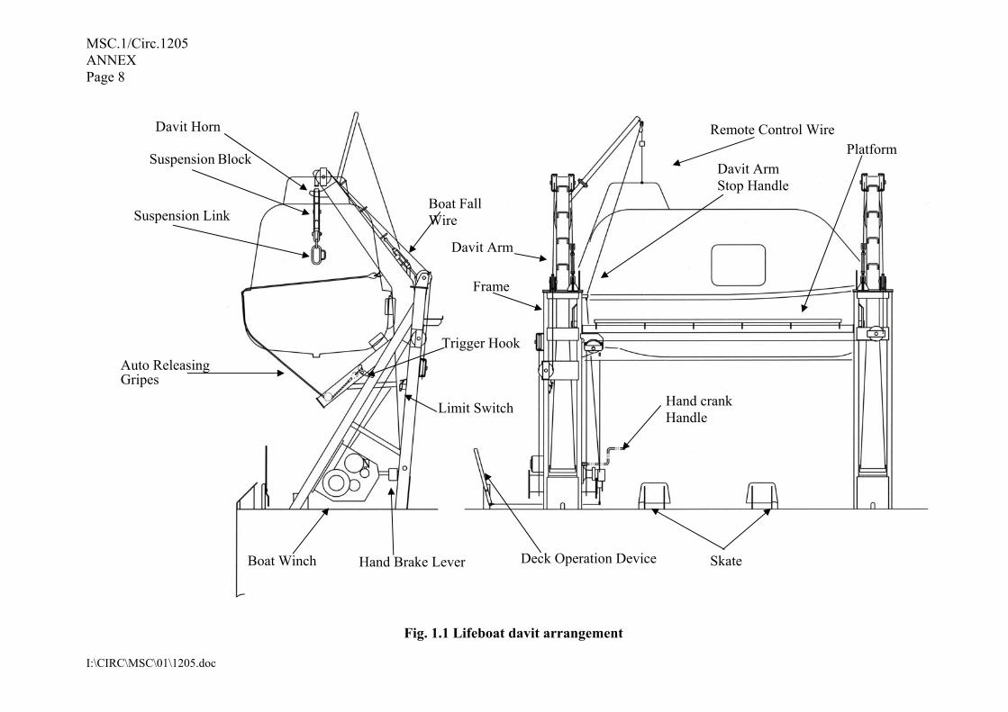
1 General The lifeboats are stored on the boat davits on both sides of the ship. In case of emergency, the crew can board the lifeboat and escaped with the lifeboat directly from its stowage position. The launching appliance consists of a boat davit (davit arm, frame, platform, falls, suspension block, and gripes/lashing device) and a boat winch (reduction gears, hand brake and centrifugal brake). Swinging out and lowering of the lifeboat can be controlled both from the inside of the lifeboat and at the ship’s deck. The lowering speed of the lifeboat can be controlled by operating the remote control wire inside the lifeboat or by operating the remote control lever on the ship’s deck. Moreover, it is possible to suspend the lowering operation of the lifeboat at any height. Recovery of the lifeboat is performed by operating the boat winch with the push-button switch box. When the davit arm reaches a prescribed position, the boat winch is automatically stopped by the limit switch. After the activation of the limit switch, the boat winch is operated manually to wind up the lifeboat to its stowage position. The boat winch is provided with a safety device to prevent the reverse operation of the manual handle. The lifeboat is equipped with on-load/off-load release gear which complies with the requirements of the IMO Life-Saving Appliance (LSA) Code. The release gear system is equipped with a hydrostatic interlock system so that it will normally not release the hooks until the boat is waterborne. To avoid possible injury or death, read this manual carefully before using the boat davit, the boat winch, and the on-load/off-load release gear.
MSC.1/Circ.1205 ANNEX Page 8
I:\CIRC\MSC\01\1205.doc
Suspension Link
Davit Arm Stop Handle
Remote Control Wire Platform
Auto Releasing Gripes
Boat Winch Hand Brake Lever Deck Operation Device
Hand crank Handle
Skate
Boat Fall Wire
Davit Arm
Trigger Hook
Limit Switch
Frame
Suspension Block
Davit Horn
Fig. 1.1 Lifeboat davit arrangement
MSC.1/Circ.1205 ANNEX
Page 9
I:\CIRC\MSC\01\1205.doc
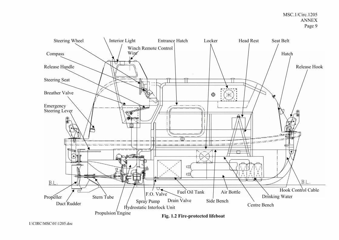
Release Hook
Duct Rudder
Propulsion Engine
Fuel Oil Tank
Centre Bench
Hook Control Cable
Steering Wheel Entrance Hatch Interior Light Locker Head Rest Seat Belt
HatchCompass
Release Handle
Steering Seat
Breather Valve
Emergency Steering Lever
Propeller Stern Tube
Hydrostatic Interlock Unit
Drinking WaterSide Bench
Winch Remote Control Wire
Spray Pump
Air Bottle
Drain Valve F.O. Valve
Fig. 1.2 Fire-protected lifeboat
MSC.1/Circ.1205 ANNEX Page 10
I:\CIRC\MSC\01\1205.doc
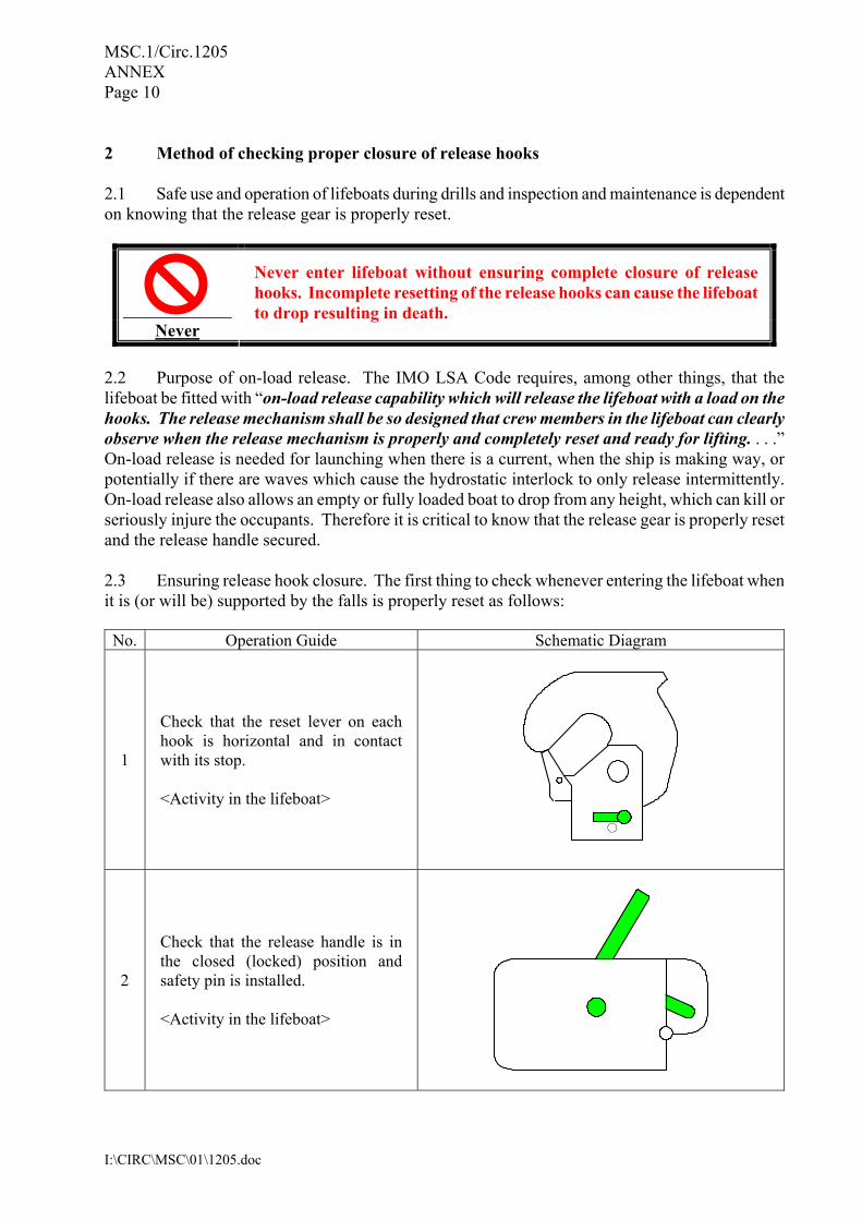
2 Method of checking proper closure of release hooks 2.1 Safe use and operation of lifeboats during drills and inspection and maintenance is dependent on knowing that the release gear is properly reset.
Never
Never enter lifeboat without ensuring complete closure of release hooks. Incomplete resetting of the release hooks can cause the lifeboat to drop resulting in death.
2.2 Purpose of on-load release. The IMO LSA Code requires, among other things, that the lifeboat be fitted with “on-load release capability which will release the lifeboat with a load on the hooks. The release mechanism shall be so designed that crew members in the lifeboat can clearly observe when the release mechanism is properly and completely reset and ready for lifting. . . .” On-load release is needed for launching when there is a current, when the ship is making way, or potentially if there are waves which cause the hydrostatic interlock to only release intermittently. On-load release also allows an empty or fully loaded boat to drop from any height, which can kill or seriously injure the occupants. Therefore it is critical to know that the release gear is properly reset and the release handle secured. 2.3 Ensuring release hook closure. The first thing to check whenever entering the lifeboat when it is (or will be) supported by the falls is properly reset as follows: No. Operation Guide Schematic Diagram
1
Check that the reset lever on each hook is horizontal and in contact with its stop. <Activity in the lifeboat>
2
Check that the release handle is in the closed (locked) position and safety pin is installed. <Activity in the lifeboat>
○

MSC.1/Circ.1205 ANNEX Page 11
I:\CIRC\MSC\01\1205.doc
3 Launching operation 3.1 Preparation before launching
No. Operation Guide Schematic Diagram
1
Prepare transceivers, and confirm the communication condition. <Activity on the ship>
2
<In case of drill> Connect the push-button switch for recovering to the receptacle. <Activity on the ship>
3
<In case of drill> Turn on the power switch of start panel.
Detach the cable for the storage battery charge.
<Activity on the ship>
4 Don life jackets. <Activity on the ship>
Receptacle
MSC.1/Circ.1205 ANNEX Page 12
I:\CIRC\MSC\01\1205.doc
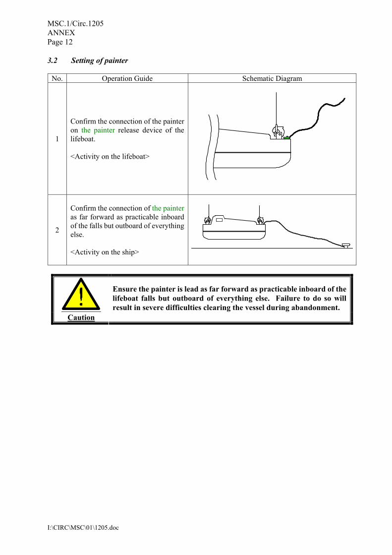
3.2 Setting of painter
No. Operation Guide Schematic Diagram
1
Confirm the connection of the painter on the painter release device of the lifeboat. <Activity on the lifeboat>
2
Confirm the connection of the painter as far forward as practicable inboard of the falls but outboard of everything else. <Activity on the ship>
Caution
Ensure the painter is lead as far forward as practicable inboard of the lifeboat falls but outboard of everything else. Failure to do so will result in severe difficulties clearing the vessel during abandonment.
MSC.1/Circ.1205 ANNEX Page 13
I:\CIRC\MSC\01\1205.doc
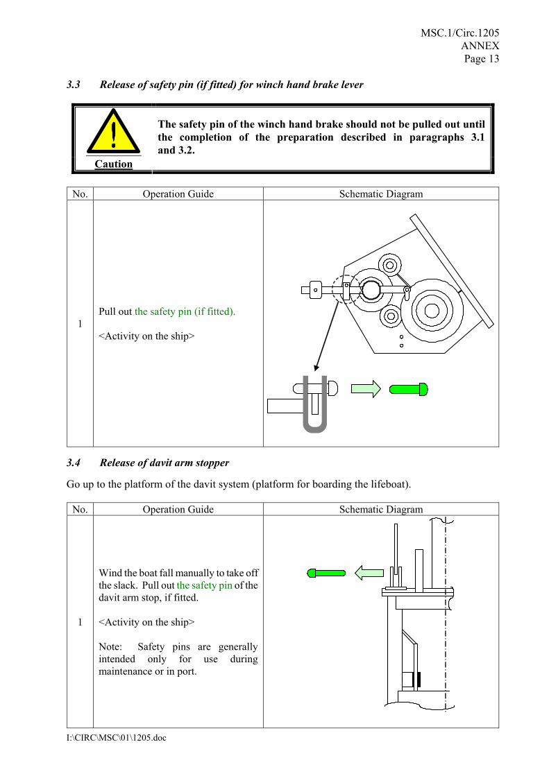
3.3 Release of safety pin (if fitted) for winch hand brake lever
Caution
The safety pin of the winch hand brake should not be pulled out until the completion of the preparation described in paragraphs 3.1 and 3.2.
No. Operation Guide Schematic Diagram
1 Pull out the safety pin (if fitted). <Activity on the ship>
3.4 Release of davit arm stopper
Go up to the platform of the davit system (platform for boarding the lifeboat).
No. Operation Guide Schematic Diagram
1
Wind the boat fall manually to take off the slack. Pull out the safety pin of the davit arm stop, if fitted. <Activity on the ship> Note: Safety pins are generally intended only for use during maintenance or in port.

MSC.1/Circ.1205 ANNEX Page 14
I:\CIRC\MSC\01\1205.doc
No. Operation Guide Schematic Diagram
2
Release the davit arm stop by operating the handle. <Activity on the ship>
Caution
The handle should be fully operated to prevent the davit arm stop from being caught with the lock device.
3.5 Boarding the lifeboat
No. Operation Guide Schematic Diagram
1
Confirm that the remote control wire is drawn into the lifeboat. <Activity on the ship>
MSC.1/Circ.1205 ANNEX Page 15
I:\CIRC\MSC\01\1205.doc
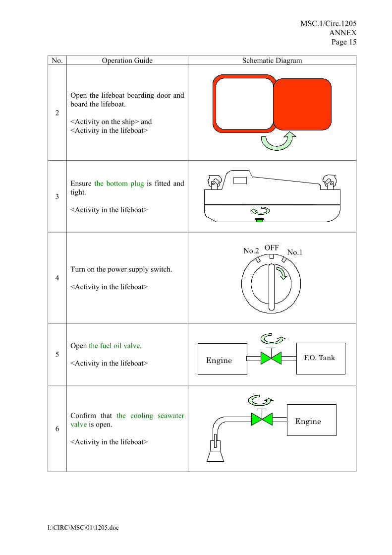
No. Operation Guide Schematic Diagram
2
Open the lifeboat boarding door and board the lifeboat. <Activity on the ship> and <Activity in the lifeboat>
3
Ensure the bottom plug is fitted and tight. <Activity in the lifeboat>
4 Turn on the power supply switch. <Activity in the lifeboat>
No.1OFFNo.2
5 Open the fuel oil valve. <Activity in the lifeboat>
Engine F.O. Tank
6
Confirm that the cooling seawater valve is open. <Activity in the lifeboat>
Engine
MSC.1/Circ.1205 ANNEX Page 16
I:\CIRC\MSC\01\1205.doc
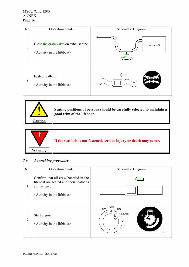
No. Operation Guide Schematic Diagram
7 Close the drain valve on exhaust pipe. <Activity in the lifeboat>
8 Fasten seatbelt. <Activity in the lifeboat>
Caution
Seating positions of persons should be carefully selected to maintain a good trim of the lifeboat.
Warning
If the seat belt is not fastened, serious injury or death may occur.
3.6 Launching procedure
No. Operation Guide Schematic Diagram
1
Confirm that all crew boarded in the lifeboat are seated and their seatbelts are fastened. <Activity in the lifeboat>
2 Start engine. <Activity in the lifeboat>
START
ONOFFGLOW
Engine
MSC.1/Circ.1205 ANNEX Page 17
I:\CIRC\MSC\01\1205.doc
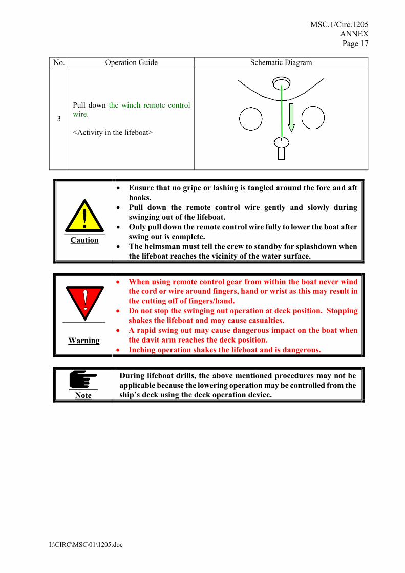
No. Operation Guide Schematic Diagram
3
Pull down the winch remote control wire. <Activity in the lifeboat>
Caution
• Ensure that no gripe or lashing is tangled around the fore and aft hooks.
• Pull down the remote control wire gently and slowly during swinging out of the lifeboat.
• Only pull down the remote control wire fully to lower the boat after swing out is complete.
• The helmsman must tell the crew to standby for splashdown when the lifeboat reaches the vicinity of the water surface.
Warning
• When using remote control gear from within the boat never wind the cord or wire around fingers, hand or wrist as this may result in the cutting off of fingers/hand.
• Do not stop the swinging out operation at deck position. Stopping shakes the lifeboat and may cause casualties.
• A rapid swing out may cause dangerous impact on the boat when the davit arm reaches the deck position.
• Inching operation shakes the lifeboat and is dangerous.
Note
During lifeboat drills, the above mentioned procedures may not be applicable because the lowering operation may be controlled from the ship’s deck using the deck operation device.
MSC.1/Circ.1205 ANNEX Page 18
I:\CIRC\MSC\01\1205.doc
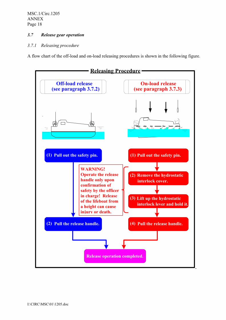
3.7 Release gear operation 3.7.1 Releasing procedure A flow chart of the off-load and on-load releasing procedures is shown in the following figure.
Releasing Procedure
Off-load release (see paragraph 3.7.2)
On-load release (see paragraph 3.7.3)
(1) Pull out the safety pin.
(2) Pull the release handle.
(2) Remove the hydrostatic interlock cover.
(3) Lift up the hydrostatic interlock lever and hold it.
(1) Pull out the safety pin.
(4) Pull the release handle.
Release operation completed.
WARNING! Operate the release handle only upon confirmation of safety by the officer in charge! Release of the lifeboat from a height can cause injury or death.
MSC.1/Circ.1205 ANNEX Page 19
I:\CIRC\MSC\01\1205.doc
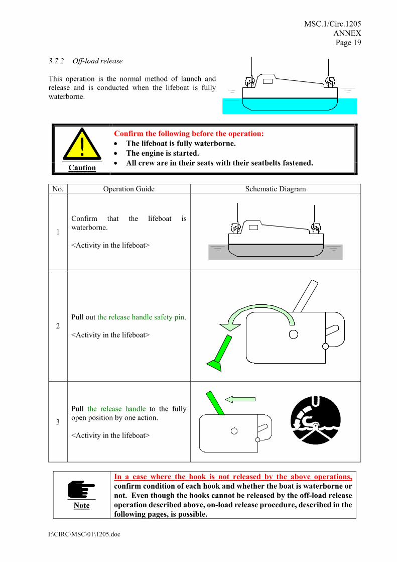
3.7.2 Off-load release This operation is the normal method of launch and release and is conducted when the lifeboat is fully waterborne.
Caution
Confirm the following before the operation: • The lifeboat is fully waterborne. • The engine is started. • All crew are in their seats with their seatbelts fastened.
No. Operation Guide Schematic Diagram
1
Confirm that the lifeboat is waterborne. <Activity in the lifeboat>
2 Pull out the release handle safety pin. <Activity in the lifeboat>
3
Pull the release handle to the fully open position by one action. <Activity in the lifeboat>
Note
In a case where the hook is not released by the above operations, confirm condition of each hook and whether the boat is waterborne or not. Even though the hooks cannot be released by the off-load release operation described above, on-load release procedure, described in the following pages, is possible.
MSC.1/Circ.1205 ANNEX Page 20
I:\CIRC\MSC\01\1205.doc
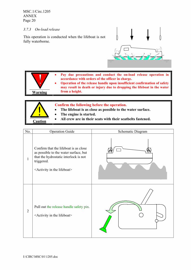
3.7.3 On-load release
This operation is conducted when the lifeboat is notfully waterborne.
Warning
• Pay due precautions and conduct the on-load release operation in accordance with orders of the officer in charge.
• Operation of the release handle upon insufficient confirmation of safety may result in death or injury due to dropping the lifeboat in the water from a height.
Caution
Confirm the following before the operation. • The lifeboat is as close as possible to the water surface. • The engine is started. • All crew are in their seats with their seatbelts fastened.
No. Operation Guide Schematic Diagram
1
Confirm that the lifeboat is as close as possible to the water surface, but that the hydrostatic interlock is not triggered. <Activity in the lifeboat>
2 Pull out the release handle safety pin. <Activity in the lifeboat>
MSC.1/Circ.1205 ANNEX Page 21
I:\CIRC\MSC\01\1205.doc
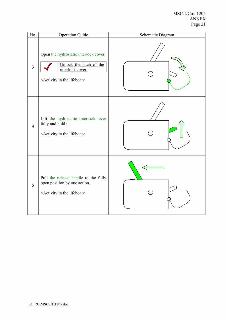
No. Operation Guide Schematic Diagram
3
Open the hydrostatic interlock cover.
Unlock the latch of the interlock cover.
<Activity in the lifeboat>
4
Lift the hydrostatic interlock lever fully and hold it. <Activity in the lifeboat>
5
Pull the release handle to the fully open position by one action. <Activity in the lifeboat>
MSC.1/Circ.1205 ANNEX Page 22
I:\CIRC\MSC\01\1205.doc
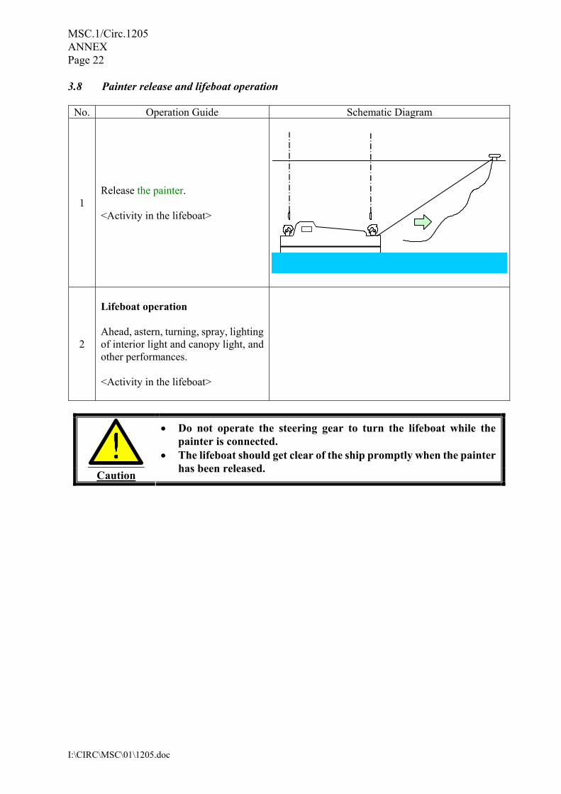
3.8 Painter release and lifeboat operation
No. Operation Guide Schematic Diagram
1 Release the painter. <Activity in the lifeboat>
2
Lifeboat operation Ahead, astern, turning, spray, lighting of interior light and canopy light, and other performances. <Activity in the lifeboat>
Caution
• Do not operate the steering gear to turn the lifeboat while the painter is connected.
• The lifeboat should get clear of the ship promptly when the painter has been released.
MSC.1/Circ.1205 ANNEX Page 23
I:\CIRC\MSC\01\1205.doc
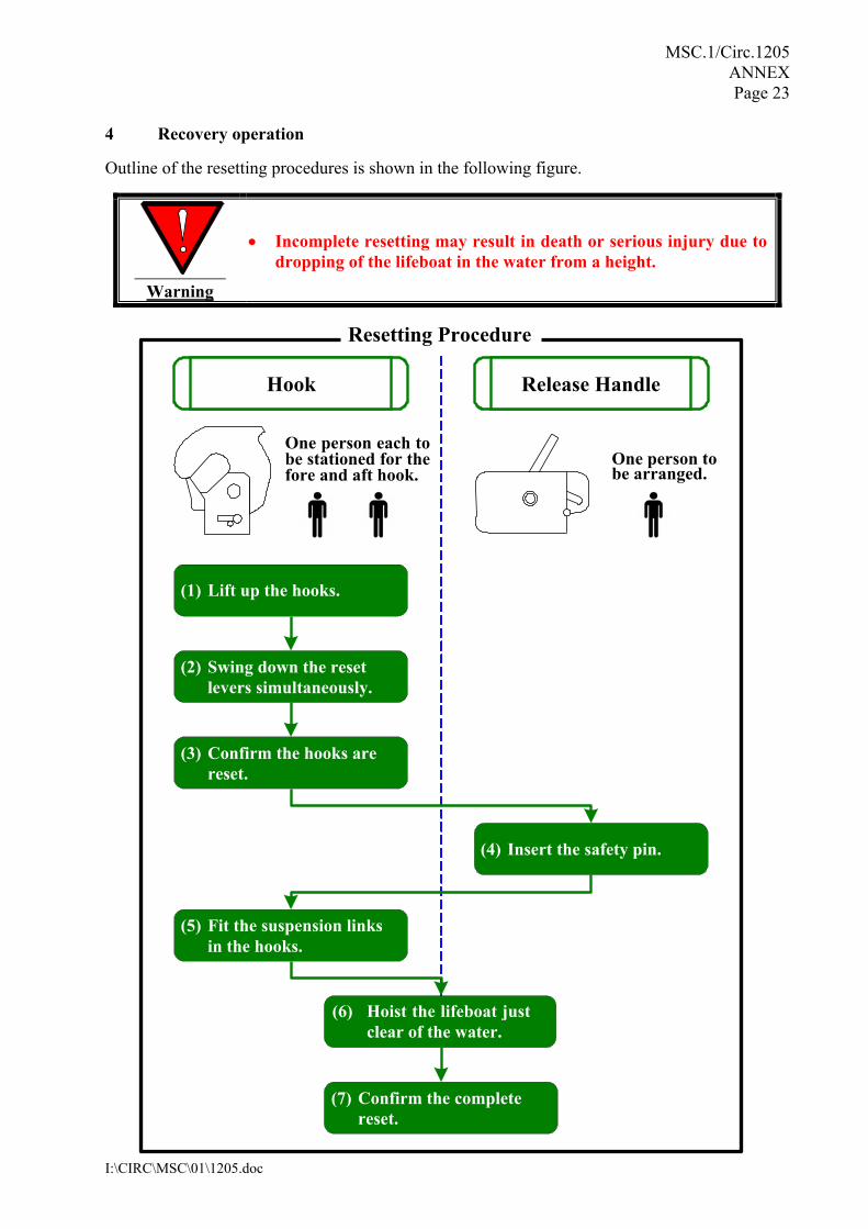
4 Recovery operation
Outline of the resetting procedures is shown in the following figure.
Warning
• Incomplete resetting may result in death or serious injury due to dropping of the lifeboat in the water from a height.
Hook Release Handle
One person each to be stationed for the fore and aft hook.
One person to
be arranged.
(1) Lift up the hooks.
(2) Swing down the resetlevers simultaneously.
(3) Confirm the hooks arereset.
(4) Insert the safety pin.
(5) Fit the suspension linksin the hooks.
(6) Hoist the lifeboat just clear of the water.
(7) Confirm the completereset.
Resetting Procedure
MSC.1/Circ.1205 ANNEX Page 24
I:\CIRC\MSC\01\1205.doc
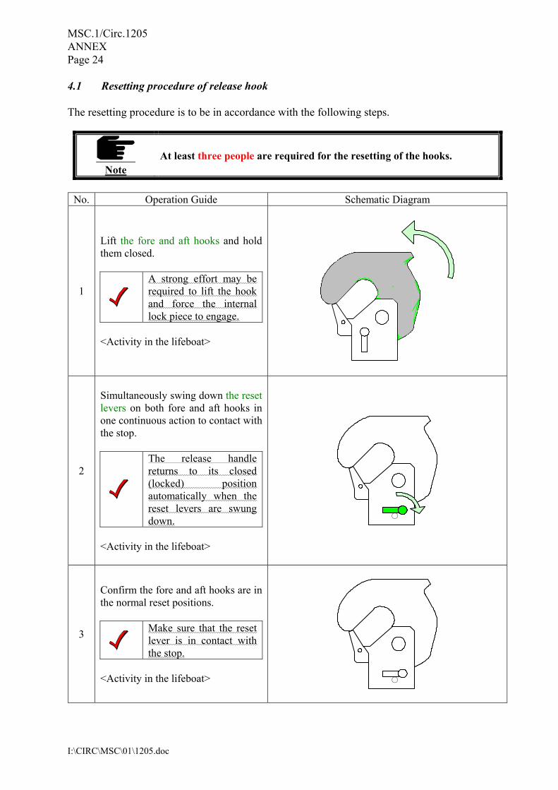
4.1 Resetting procedure of release hook The resetting procedure is to be in accordance with the following steps.
Note
At least three people are required for the resetting of the hooks.
No. Operation Guide Schematic Diagram
1
Lift the fore and aft hooks and hold them closed.
A strong effort may be required to lift the hook and force the internal lock piece to engage.
<Activity in the lifeboat>
2
Simultaneously swing down the reset levers on both fore and aft hooks in one continuous action to contact with the stop.
The release handle returns to its closed (locked) position automatically when the reset levers are swung down.
<Activity in the lifeboat>
○
3
Confirm the fore and aft hooks are in the normal reset positions.
Make sure that the reset lever is in contact with the stop.
<Activity in the lifeboat>
○

MSC.1/Circ.1205 ANNEX Page 25
I:\CIRC\MSC\01\1205.doc
No. Operation Guide Schematic Diagram
4
Make sure that the release handle is in the closed (locked) position and insert the safety pin.
If the release handle is not in its closed (locked) position, it is not possible to insert the safety pin.
<Activity in the lifeboat>
4.2 Recovery procedure The recovery procedure is to be in accordance with the following steps only after completing the release gear resetting.
Warning
• Great care must be exercised in reconnecting the hooks that hands and fingers are kept clear.
• Failure to confirm proper resetting or to follow all steps below may result in death or serious injury due to dropping the lifeboat in water from a height.
4.2.1 Connection of the suspension link
No. Operation Guide Schematic Diagram
1
Manoeuvre the lifeboat to come under boat falls.
2
Adjust the heights of the suspension links by raising or lowering the boat falls. <Activity on the ship> and <Activity in the lifeboat> under good communication.
MSC.1/Circ.1205 ANNEX Page 26
I:\CIRC\MSC\01\1205.doc
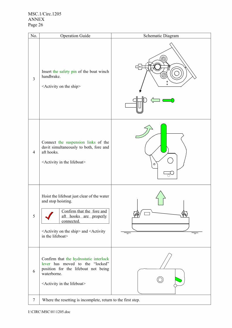
No. Operation Guide Schematic Diagram
3
Insert the safety pin of the boat winch handbrake. <Activity on the ship>
4
Connect the suspension links of the davit simultaneously to both, fore and aft hooks. <Activity in the lifeboat>
○
5
Hoist the lifeboat just clear of the water and stop hoisting.
Confirm that the fore and aft hooks are properly connected.
<Activity on the ship> and <Activity in the lifeboat>
6
Confirm that the hydrostatic interlock lever has moved to the “locked” position for the lifeboat not being waterborne. <Activity in the lifeboat>
7 Where the resetting is incomplete, return to the first step.
MSC.1/Circ.1205 ANNEX Page 27
I:\CIRC\MSC\01\1205.doc
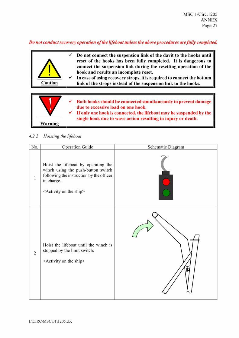
Do not conduct recovery operation of the lifeboat unless the above procedures are fully completed.
Caution
Do not connect the suspension link of the davit to the hooks until reset of the hooks has been fully completed. It is dangerous to connect the suspension link during the resetting operation of the hook and results an incomplete reset.
In case of using recovery strops, it is required to connect the bottom link of the strops instead of the suspension link to the hooks.
Warning
Both hooks should be connected simultaneously to prevent damage due to excessive load on one hook.
If only one hook is connected, the lifeboat may be suspended by the single hook due to wave action resulting in injury or death.
4.2.2 Hoisting the lifeboat
No. Operation Guide Schematic Diagram
1
Hoist the lifeboat by operating the winch using the push-button switch following the instruction by the officer in charge. <Activity on the ship>
2
Hoist the lifeboat until the winch is stopped by the limit switch. <Activity on the ship>
MSC.1/Circ.1205 ANNEX Page 28
I:\CIRC\MSC\01\1205.doc
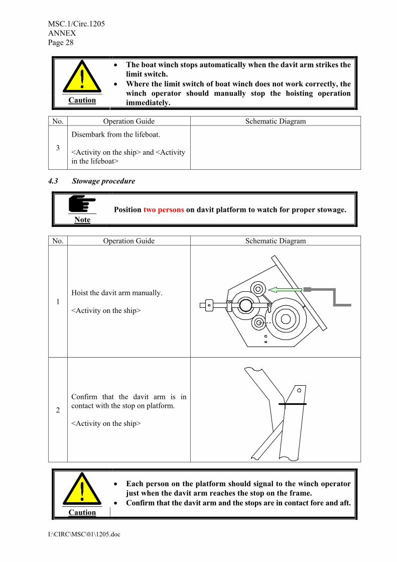
Caution
• The boat winch stops automatically when the davit arm strikes the limit switch.
• Where the limit switch of boat winch does not work correctly, the winch operator should manually stop the hoisting operation immediately.
No. Operation Guide Schematic Diagram
3
Disembark from the lifeboat. <Activity on the ship> and <Activity in the lifeboat>
4.3 Stowage procedure
Note
Position two persons on davit platform to watch for proper stowage.
No. Operation Guide Schematic Diagram
1 Hoist the davit arm manually. <Activity on the ship>
2
Confirm that the davit arm is in contact with the stop on platform. <Activity on the ship>
Caution
• Each person on the platform should signal to the winch operator just when the davit arm reaches the stop on the frame.
• Confirm that the davit arm and the stops are in contact fore and aft.
MSC.1/Circ.1205 ANNEX Page 29
I:\CIRC\MSC\01\1205.doc
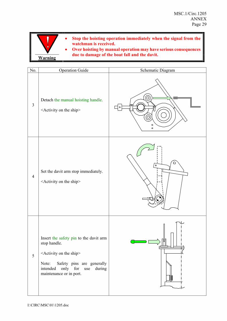
Warning
• Stop the hoisting operation immediately when the signal from the watchman is received.
• Over hoisting by manual operation may have serious consequences due to damage of the boat fall and the davit.
No. Operation Guide Schematic Diagram
3 Detach the manual hoisting handle. <Activity on the ship>
4 Set the davit arm stop immediately. <Activity on the ship>
5
Insert the safety pin to the davit arm stop handle. <Activity on the ship> Note: Safety pins are generally intended only for use during maintenance or in port.
MSC.1/Circ.1205 ANNEX Page 30
I:\CIRC\MSC\01\1205.doc
No. Operation Guide Schematic Diagram
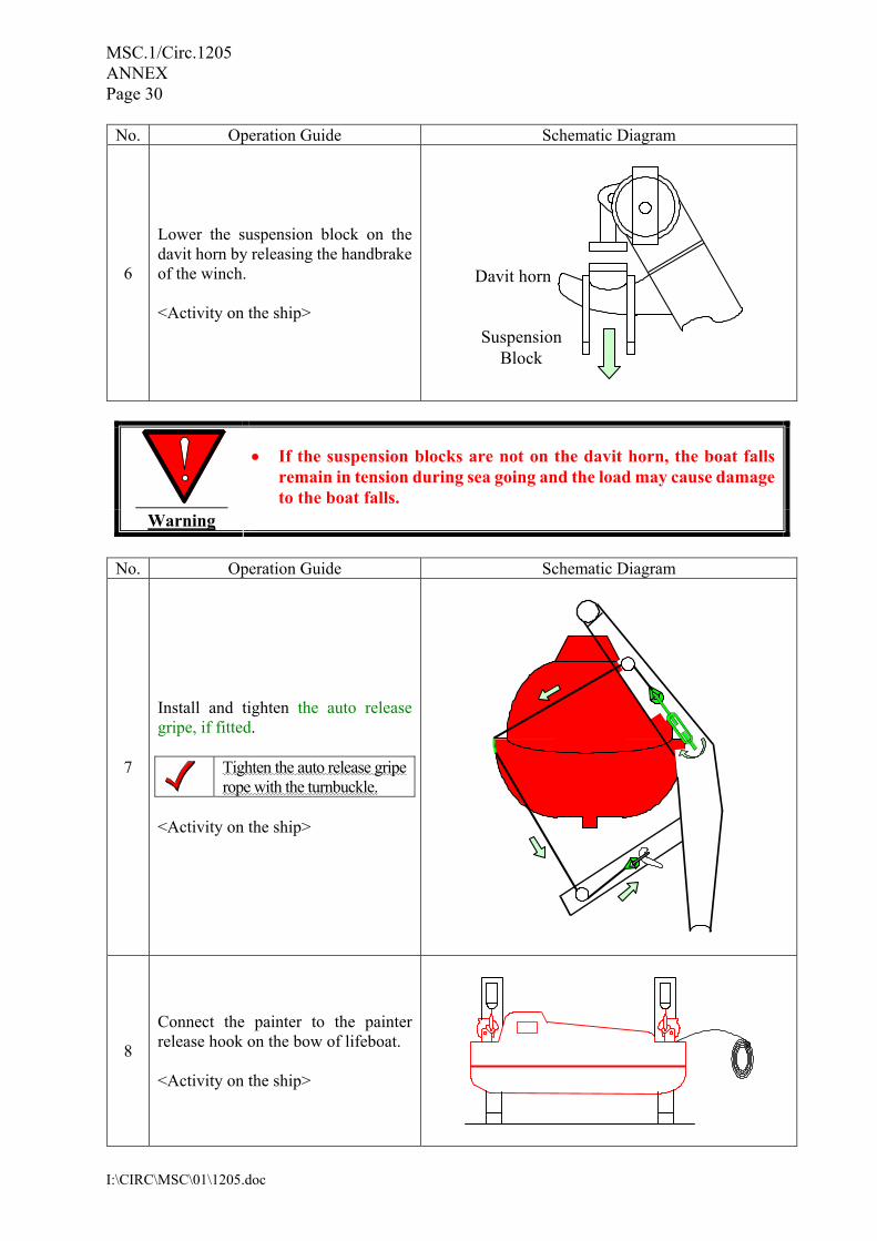
6
Lower the suspension block on the davit horn by releasing the handbrake of the winch. <Activity on the ship>
Davit horn
SuspensionBlock
Warning
• If the suspension blocks are not on the davit horn, the boat falls remain in tension during sea going and the load may cause damage to the boat falls.
No. Operation Guide Schematic Diagram
7
Install and tighten the auto release gripe, if fitted.
Tighten the auto release gripe rope with the turnbuckle.
<Activity on the ship>
8
Connect the painter to the painter release hook on the bow of lifeboat. <Activity on the ship>

MSC.1/Circ.1205 ANNEX Page 31
I:\CIRC\MSC\01\1205.doc
5 On-load/off-load release gear system 5.1 General This section describes the details of the release gear system. Read this section carefully for safe operation. This release gear system consists of fore and aft hooks, a release handle near the steering console, a hydrostatic unit and the associated cables (see Fig. 5.1). The releasing operation of the hooks is conducted at the release handle near the steering console through the control cables terminating at the fore and aft hooks. The interlock system including the hydrostatic interlock unit is provided to prevent the release of the hooks when the boat is not waterborne. The system also has an on-load release function which makes it possible to over-ride the interlock by the hydrostatic unit. Incorrect on-load release operation may cause fatalities and due precautions should be taken for this operation.
Fig. 5.1 Schematic of release gear system
Fore hook unit
Aft hook unit
Hydrostatic interlock unit
Control cables
Interlock cable
MSC.1/Circ.1205 ANNEX Page 32
I:\CIRC\MSC\01\1205.doc
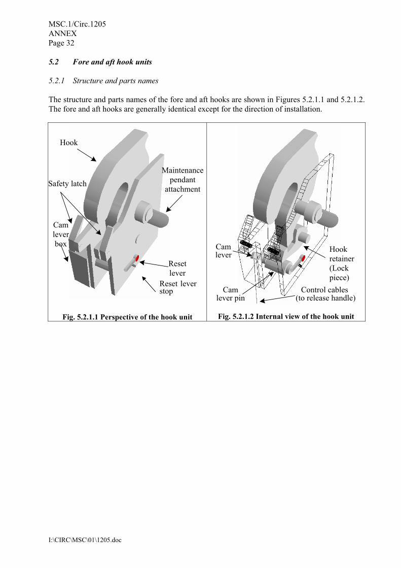
5.2 Fore and aft hook units 5.2.1 Structure and parts names The structure and parts names of the fore and aft hooks are shown in Figures 5.2.1.1 and 5.2.1.2. The fore and aft hooks are generally identical except for the direction of installation.
Fig. 5.2.1.1 Perspective of the hook unit
Fig. 5.2.1.2 Internal view of the hook unit
Hook
Safety latch
Reset lever
Maintenance pendant
attachment
Cam lever box
Cam
lever pin
Hook retainer (Lock piece)
Camlever
Control cables (to release handle)
Reset lever stop
MSC.1/Circ.1205 ANNEX Page 33
I:\CIRC\MSC\01\1205.doc
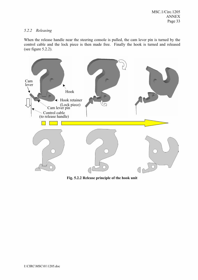
5.2.2 Releasing When the release handle near the steering console is pulled, the cam lever pin is turned by the control cable and the lock piece is then made free. Finally the hook is turned and released (see figure 5.2.2).
Fig. 5.2.2 Release principle of the hook unit
Hook
Hook retainer (Lock piece)
Cam lever pin Control cable
(to release handle)
Cam lever
MSC.1/Circ.1205 ANNEX Page 34
I:\CIRC\MSC\01\1205.doc
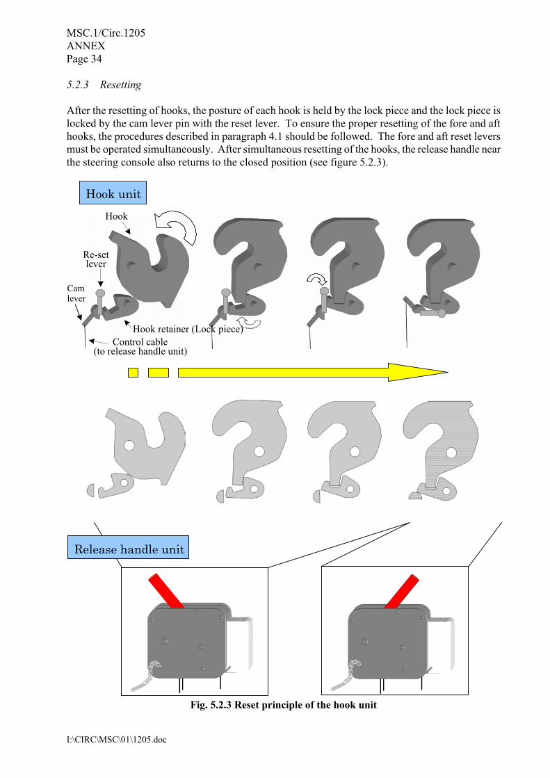
5.2.3 Resetting After the resetting of hooks, the posture of each hook is held by the lock piece and the lock piece is locked by the cam lever pin with the reset lever. To ensure the proper resetting of the fore and aft hooks, the procedures described in paragraph 4.1 should be followed. The fore and aft reset levers must be operated simultaneously. After simultaneous resetting of the hooks, the release handle near the steering console also returns to the closed position (see figure 5.2.3).
Fig. 5.2.3 Reset principle of the hook unit
Hook unit
Hook
Re-set lever
Hook retainer (Lock piece)Control cable
(to release handle unit)
Release handle unit
Cam lever
MSC.1/Circ.1205 ANNEX Page 35
I:\CIRC\MSC\01\1205.doc
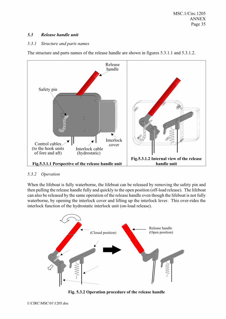
5.3 Release handle unit 5.3.1 Structure and parts names The structure and parts names of the release handle are shown in figures 5.3.1.1 and 5.3.1.2.
Fig.5.3.1.1 Perspective of the release handle unit
Fig.5.3.1.2 Internal view of the release
handle unit 5.3.2 Operation When the lifeboat is fully waterborne, the lifeboat can be released by removing the safety pin and then pulling the release handle fully and quickly to the open position (off-load release). The lifeboat can also be released by the same operation of the release handle even though the lifeboat is not fully waterborne, by opening the interlock cover and lifting up the interlock lever. This over-rides the interlock function of the hydrostatic interlock unit (on-load release).
Fig. 5.3.2 Operation procedure of the release handle
Safety pin
Releasehandle
Control cables (to the hook units of fore and aft)
Interlock cable(hydrostatic)
Interlockcover
Release handle (Open position) (Closed position)

MSC.1/Circ.1205 ANNEX Page 36
I:\CIRC\MSC\01\1205.doc
5.4 Hydrostatic interlock unit 5.4.1 Structure and parts name Structure and parts names of the hydrostatic interlock unit are shown in figures 5.4.1.1 and 5.4.1.2.
Fig. 5.4.1.1 Perspective of
the hydrostatic interlock unit
Fig. 5.4.1.2 Internal view of the hydrostatic interlock unit
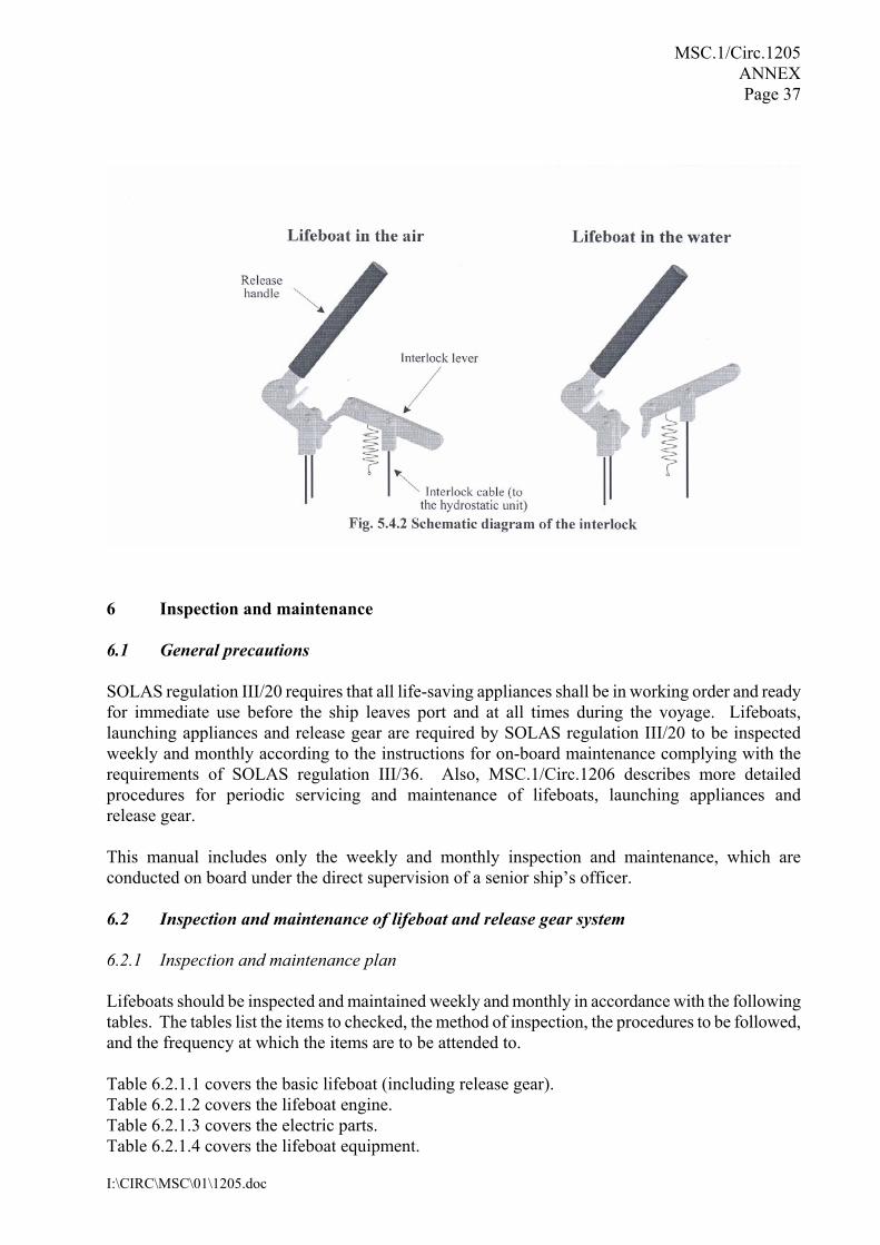
5.4.2 Operation When the lifeboat is fully waterborne, the hydrostatic interlock unit pushes up the interlock lever through the interlock cable by the water lifting the float and thus allowing the release handle to be operated. Contrary to this, operation of the release handle is not allowed by the hydrostatic interlock unit when the lifeboat is not fully waterborne.
Interlock cable ( to the hydrostaticinterlock lever of the release handle unit) Air vent
Rod Hydrostatic unit body
Flange
Water tight seal
Float
Pressure ofseawater
MSC.1/Circ.1205 ANNEX Page 37
I:\CIRC\MSC\01\1205.doc
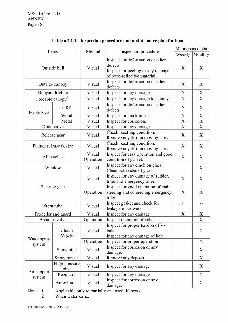
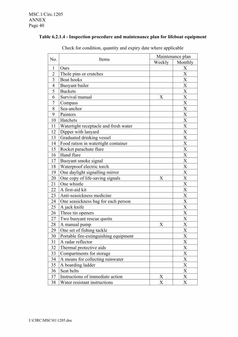
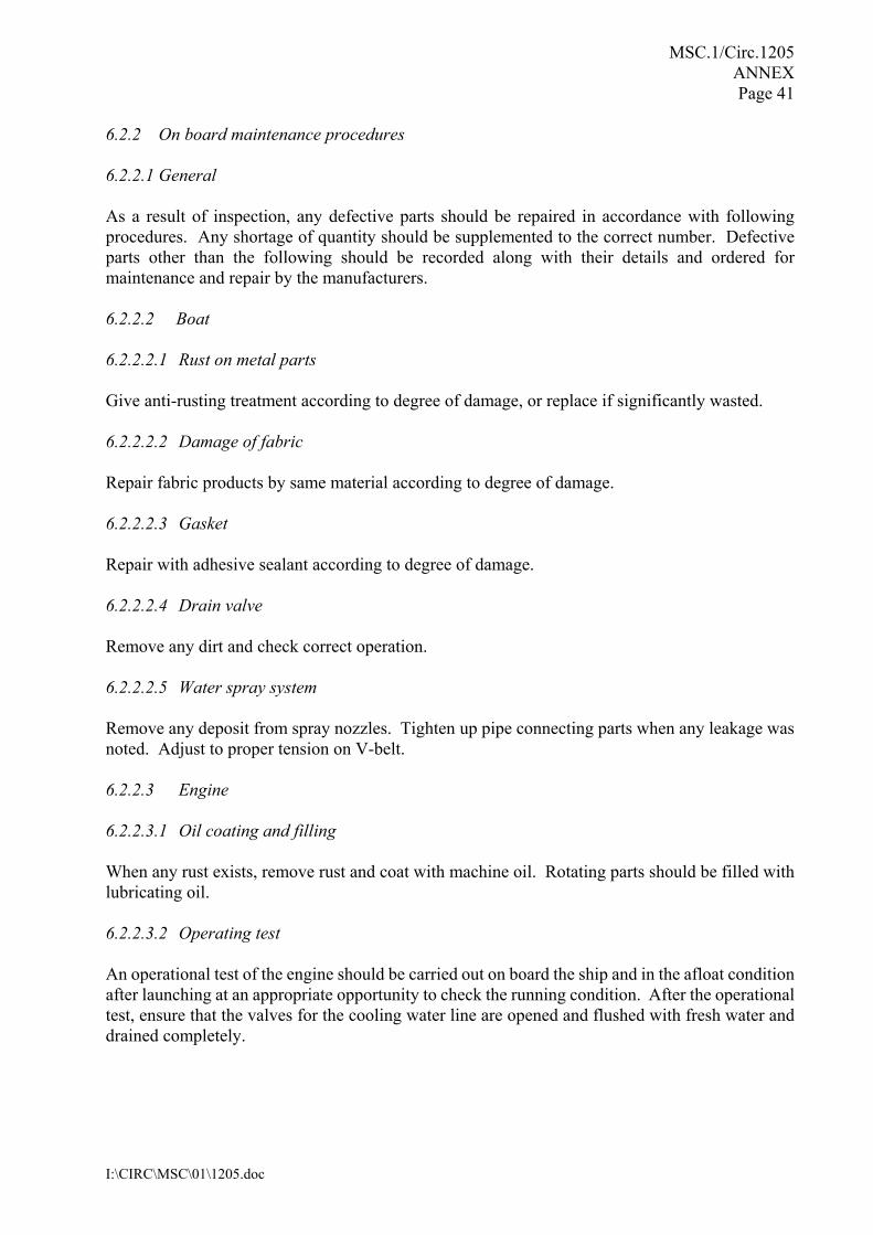
6 Inspection and maintenance 6.1 General precautions SOLAS regulation III/20 requires that all life-saving appliances shall be in working order and ready for immediate use before the ship leaves port and at all times during the voyage. Lifeboats, launching appliances and release gear are required by SOLAS regulation III/20 to be inspected weekly and monthly according to the instructions for on-board maintenance complying with the requirements of SOLAS regulation III/36. Also, MSC.1/Circ.1206 describes more detailed procedures for periodic servicing and maintenance of lifeboats, launching appliances and release gear. This manual includes only the weekly and monthly inspection and maintenance, which are conducted on board under the direct supervision of a senior ship’s officer. 6.2 Inspection and maintenance of lifeboat and release gear system 6.2.1 Inspection and maintenance plan Lifeboats should be inspected and maintained weekly and monthly in accordance with the following tables. The tables list the items to checked, the method of inspection, the procedures to be followed, and the frequency at which the items are to be attended to. Table 6.2.1.1 covers the basic lifeboat (including release gear). Table 6.2.1.2 covers the lifeboat engine. Table 6.2.1.3 covers the electric parts. Table 6.2.1.4 covers the lifeboat equipment.
MSC.1/Circ.1205 ANNEX Page 38
I:\CIRC\MSC\01\1205.doc
Table 6.2.1.1 - Inspection procedure and maintenance plan for boat
Maintenance planItems Method Inspection procedure Weekly Monthly
Outside hull Visual
Inspect for deformation or other defects. Inspect for peeling or any damage of retro-reflective material.
X X
Outside canopy Visual Inspect for deformation or other defects. X X
Buoyant lifeline Visual Inspect for any damage. X X Foldable canopy*1 Visual Inspect for any damage to canopy. X X
GRP Visual Inspect for deformation or other defects. X X
Wood Visual Inspect for crack or rot. X X Inside boat
Metal Visual Inspect for corrosion. X X Drain valve Visual Inspect for any damage. X X
Release gear Visual Check resetting condition. Remove any dirt on moving parts. X X
Painter release device Visual Check resetting condition. Remove any dirt on moving parts. X X
All hatches Visual Operation
Inspect for easy operation and good condition of gasket. X X
Window Visual Inspect for any crack on glass. Clean both sides of glass. X
Visual Inspect for any damage of rudder, tiller and emergency tiller. X X
Steering gear Operation
Inspect for good operation of main steering and connecting emergency tiller.
X X
Stern tube Visual Inspect gasket and check for leakage of seawater.
*2 *2
Propeller and guard Visual Inspect for any damage. X X Breather valve Operation Inspect operation of valve. X
Visual Inspect for proper tension of V-belt. Inspect for any damage of belt.
X Clutch V-belt
Operation Inspect for proper operation. X
Spray pipe Visual Inspect for corrosion or any damage. X
Water spray system
Spray nozzle Visual Remove any deposit. X High pressure
pipe Visual Inspect for any damage. X
Regulator Visual Inspect for any damage. X Air support system
Air cylinder Visual Inspect for corrosion or any damage. X
Note: 1 Applicable only to partially enclosed lifeboats. 2 When waterborne.

MSC.1/Circ.1205 ANNEX Page 39
I:\CIRC\MSC\01\1205.doc
Table 6.2.1.2 - Inspection procedure and maintenance plan for engine
Maintenance planItems Method Inspection procedure
Weekly MonthlyVisual Check in good condition. X
Engine Operation Start and operate the engine. Check operation of throttle. Check operation of clutch.
X X
Visual Check an amount of oil. X Lubricating oil Visual Check viscosity of oil with finger
and ensure it’s not dirty. X
Fuel oil tank Visual
Check securing condition of the tank (corrosion or leakage and connecting parts). Check an amount of fuel oil.
X
Fuel oil pipe Visual Check any leakage on connecting parts. X
Water cooler Visual Check an amount of fresh water. X Cooling water pipe Visual Check any leakage on pipe. X
Starter switch Operation Check operating properly. X X Glow lamp Operation Check light on when pre-heating. X X
Tachometer Operation Check proper indication of revolution. X X
Oil pressure warning lamp, Charge lamp Operation Check proper light on or light off
condition. X X
Stop wire Operation Stop the engine. X X
Table 6.2.1.3 - Inspection procedure and maintenance plan for electric parts
Maintenance planItems Method Inspection procedure
Weekly MonthlyVisual Check lead wire. X
Battery Measure Measure voltage of battery. When voltage is low, charge battery. X
Inside lamp Operation Check light on. X Canopy lamp Operation Check light on. X Search light Operation Check light on. X
Electric wiring Visual Check any defects on wiring. X
MSC.1/Circ.1205 ANNEX Page 40
I:\CIRC\MSC\01\1205.doc
Table 6.2.1.4 - Inspection procedure and maintenance plan for lifeboat equipment
Check for condition, quantity and expiry date where applicable
Maintenance plan No. Items Weekly Monthly 1 Oars X 2 Thole pins or crutches X 3 Boat hooks X 4 Buoyant bailer X 5 Buckets X 6 Survival manual X X 7 Compass X 8 Sea-anchor X 9 Painters X 10 Hatchets X 11 Watertight receptacle and fresh water X 12 Dipper with lanyard X 13 Graduated drinking vessel X 14 Food ration in watertight container X 15 Rocket parachute flare X 16 Hand flare X 17 Buoyant smoke signal X 18 Waterproof electric torch X 19 One daylight signalling mirror X 20 One copy of life-saving signals X X 21 One whistle X 22 A first-aid kit X 23 Anti-seasickness medicine X 24 One seasickness bag for each person X 25 A jack knife X 26 Three tin openers X 27 Two buoyant rescue quoits X 28 A manual pump X X 29 One set of fishing tackle X 30 Portable fire-extinguishing equipment X 31 A radar reflector X 32 Thermal protective aids X 33 Compartments for storage X 34 A means for collecting rainwater X 35 A boarding ladder X 36 Seat belts X 37 Instructions of immediate action X X 38 Water resistant instructions X X
MSC.1/Circ.1205 ANNEX Page 41
I:\CIRC\MSC\01\1205.doc
6.2.2 On board maintenance procedures 6.2.2.1 General As a result of inspection, any defective parts should be repaired in accordance with following procedures. Any shortage of quantity should be supplemented to the correct number. Defective parts other than the following should be recorded along with their details and ordered for maintenance and repair by the manufacturers. 6.2.2.2 Boat 6.2.2.2.1 Rust on metal parts Give anti-rusting treatment according to degree of damage, or replace if significantly wasted. 6.2.2.2.2 Damage of fabric Repair fabric products by same material according to degree of damage. 6.2.2.2.3 Gasket Repair with adhesive sealant according to degree of damage. 6.2.2.2.4 Drain valve Remove any dirt and check correct operation. 6.2.2.2.5 Water spray system Remove any deposit from spray nozzles. Tighten up pipe connecting parts when any leakage was noted. Adjust to proper tension on V-belt. 6.2.2.3 Engine 6.2.2.3.1 Oil coating and filling When any rust exists, remove rust and coat with machine oil. Rotating parts should be filled with lubricating oil. 6.2.2.3.2 Operating test An operational test of the engine should be carried out on board the ship and in the afloat condition after launching at an appropriate opportunity to check the running condition. After the operational test, ensure that the valves for the cooling water line are opened and flushed with fresh water and drained completely.
MSC.1/Circ.1205 ANNEX Page 42
I:\CIRC\MSC\01\1205.doc
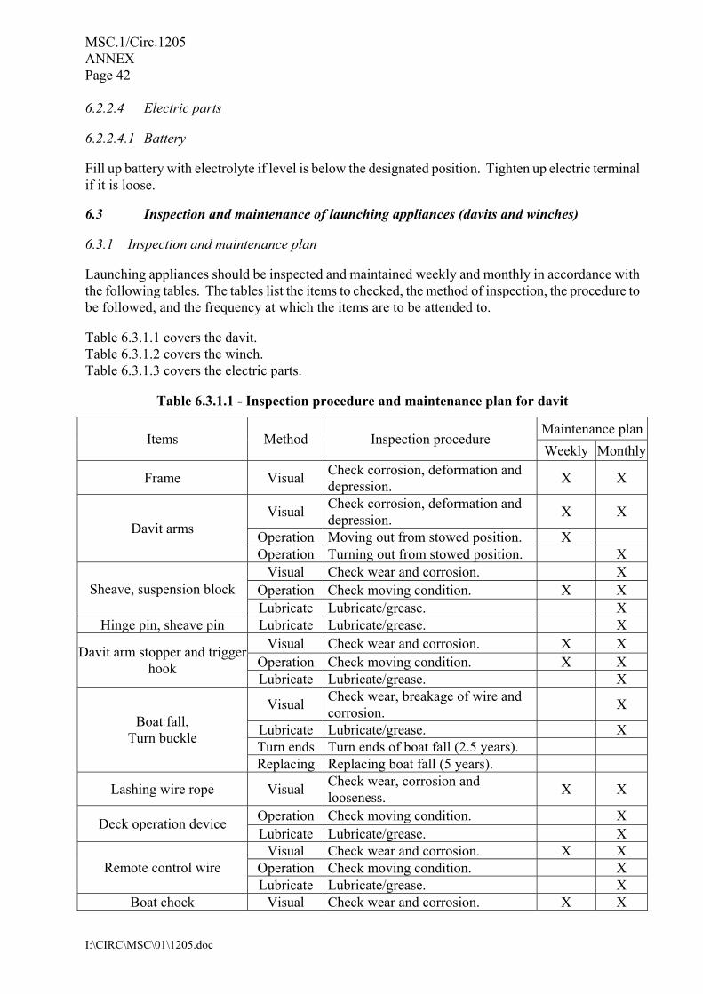
6.2.2.4 Electric parts 6.2.2.4.1 Battery Fill up battery with electrolyte if level is below the designated position. Tighten up electric terminal if it is loose. 6.3 Inspection and maintenance of launching appliances (davits and winches) 6.3.1 Inspection and maintenance plan Launching appliances should be inspected and maintained weekly and monthly in accordance with the following tables. The tables list the items to checked, the method of inspection, the procedure to be followed, and the frequency at which the items are to be attended to. Table 6.3.1.1 covers the davit. Table 6.3.1.2 covers the winch. Table 6.3.1.3 covers the electric parts.
Table 6.3.1.1 - Inspection procedure and maintenance plan for davit
Maintenance planItems Method Inspection procedure
Weekly Monthly
Frame Visual Check corrosion, deformation and depression. X X
Visual Check corrosion, deformation and depression. X X
Operation Moving out from stowed position. X Davit arms
Operation Turning out from stowed position. X Visual Check wear and corrosion. X
Operation Check moving condition. X X Sheave, suspension block Lubricate Lubricate/grease. X
Hinge pin, sheave pin Lubricate Lubricate/grease. X Visual Check wear and corrosion. X X
Operation Check moving condition. X X Davit arm stopper and trigger
hook Lubricate Lubricate/grease. X
Visual Check wear, breakage of wire and corrosion. X
Lubricate Lubricate/grease. X Turn ends Turn ends of boat fall (2.5 years).
Boat fall, Turn buckle
Replacing Replacing boat fall (5 years).
Lashing wire rope Visual Check wear, corrosion and looseness. X X
Operation Check moving condition. X Deck operation device Lubricate Lubricate/grease. X
Visual Check wear and corrosion. X X Operation Check moving condition. X Remote control wire Lubricate Lubricate/grease. X
Boat chock Visual Check wear and corrosion. X X
MSC.1/Circ.1205 ANNEX Page 43
I:\CIRC\MSC\01\1205.doc
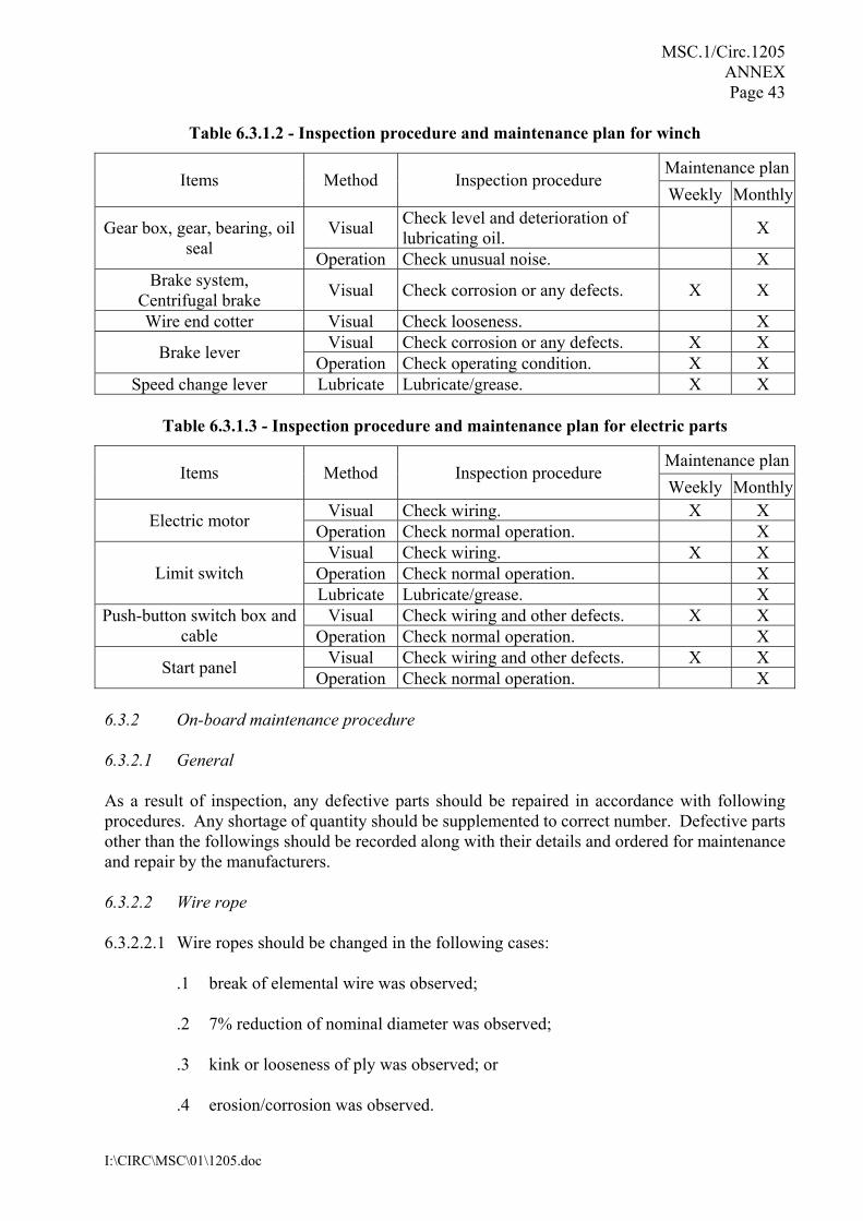
Table 6.3.1.2 - Inspection procedure and maintenance plan for winch
Maintenance planItems Method Inspection procedure
Weekly Monthly
Visual Check level and deterioration of lubricating oil. X Gear box, gear, bearing, oil
seal Operation Check unusual noise. X Brake system,
Centrifugal brake Visual Check corrosion or any defects. X X
Wire end cotter Visual Check looseness. X Visual Check corrosion or any defects. X X Brake lever Operation Check operating condition. X X
Speed change lever Lubricate Lubricate/grease. X X
Table 6.3.1.3 - Inspection procedure and maintenance plan for electric parts
Maintenance planItems Method Inspection procedure
Weekly MonthlyVisual Check wiring. X X Electric motor Operation Check normal operation. X Visual Check wiring. X X
Operation Check normal operation. X Limit switch Lubricate Lubricate/grease. X
Visual Check wiring and other defects. X X Push-button switch box and cable Operation Check normal operation. X
Visual Check wiring and other defects. X X Start panel Operation Check normal operation. X 6.3.2 On-board maintenance procedure 6.3.2.1 General As a result of inspection, any defective parts should be repaired in accordance with following procedures. Any shortage of quantity should be supplemented to correct number. Defective parts other than the followings should be recorded along with their details and ordered for maintenance and repair by the manufacturers. 6.3.2.2 Wire rope 6.3.2.2.1 Wire ropes should be changed in the following cases:
.1 break of elemental wire was observed; .2 7% reduction of nominal diameter was observed; .3 kink or looseness of ply was observed; or .4 erosion/corrosion was observed.
MSC.1/Circ.1205 ANNEX Page 44
I:\CIRC\MSC\01\1205.doc
6.3.2.2.2 Check fixing condition of wire ropes. 6.3.2.2.3 Change the boat falls within an appropriate period. 6.3.2.2.4 Adjust the length of boat falls as necessary so that the clearances between the davit arm and davit arm stopper at fore and aft are almost the same. 6.3.2.2.5 Ensure that material and diameter of suspension links are as specified by the release gear manufacturer. 6.3.2.3 Boat winch 6.3.2.3.1 Prior to commencement of the maintenance work for the winch, the boat should be secured to prevent movement. 6.3.2.3.2 Oil should be checked and changed if discoloured. In case that oil level is low, oil should be added until the its surface comes to the designated level in the oil gauge. 6.3.2.3.3 Surfaces of each gear inside the gear box should be checked. In case that a defect is found on a surface of gear, the gear box should be replaced or repaired.
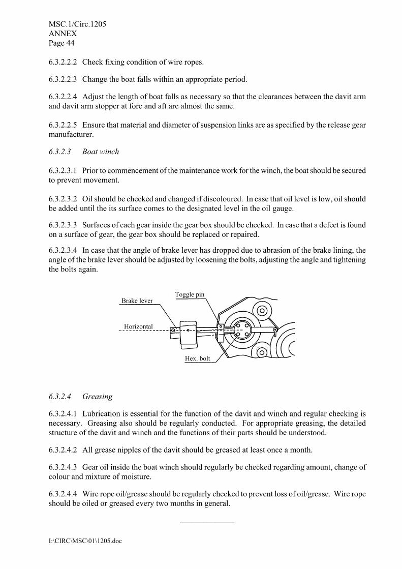
6.3.2.3.4 In case that the angle of brake lever has dropped due to abrasion of the brake lining, the angle of the brake lever should be adjusted by loosening the bolts, adjusting the angle and tightening the bolts again.
6.3.2.4 Greasing 6.3.2.4.1 Lubrication is essential for the function of the davit and winch and regular checking is necessary. Greasing also should be regularly conducted. For appropriate greasing, the detailed structure of the davit and winch and the functions of their parts should be understood. 6.3.2.4.2 All grease nipples of the davit should be greased at least once a month. 6.3.2.4.3 Gear oil inside the boat winch should regularly be checked regarding amount, change of colour and mixture of moisture. 6.3.2.4.4 Wire rope oil/grease should be regularly checked to prevent loss of oil/grease. Wire rope should be oiled or greased every two months in general.
______________
Toggle pinBrake lever
Horizontal
Hex. bolt
I:\CIRC\MSC\01\1206-Rev-1.doc
INTERNATIONAL MARITIME ORGANIZATION 4 ALBERT EMBANKMENT LONDON SE1 7SR Telephone: 020 7735 7611 Fax: 020 7587 3210
IMO
E
Ref. T4/3.01 MSC.1/Circ.1206/Rev.1 11 June 2009
MEASURES TO PREVENT ACCIDENTS WITH LIFEBOATS 1 The Maritime Safety Committee, at its eighty-first session (10 to 19 May 2006), recalled that at its seventy-fifth session (15 to 24 May 2002), it had considered the issue of the unacceptably high number of accidents with lifeboats in which crew were being injured, sometimes fatally, while participating in lifeboat drills and/or inspections, and noted that most accidents fell under the following categories:
.1 failure of on-load release mechanism; .2 inadvertent operation of on-load release mechanism; .3 inadequate maintenance of lifeboats, davits and launching equipment; .4 communication failures; .5 lack of familiarity with lifeboats, davits, equipment and associated controls; .6 unsafe practices during lifeboat drills and inspections; and .7 design faults other than on-load release mechanisms.
2 Pending further consideration of the problem, the Committee approved MSC/Circ.1049 on Accidents with lifeboats, to draw the attention of manufacturers, shipowners, crews and classification societies to the personal injury and loss of life that may follow inadequate attention to the design, construction, maintenance and operation of lifeboats, davits and associated equipment and urged all concerned to take necessary action to prevent further accidents with lifeboats. It invited Member Governments to:
.1 bring the circular to the attention of their maritime Administrations, relevant industry organizations, manufacturers, shipowners, crews and classification societies;
.2 take the necessary action to prevent further accidents with lifeboats pending the
development of appropriate IMO guidance; .3 ensure that:
.3.1 on-load release equipment used on ships flying their flag is in full compliance with the requirements of paragraphs 4.4.7.6.2.2 to 4.4.7.6.5 of the LSA Code;
.3.2 all appropriate documentation for the maintenance and adjustment of
lifeboats, launching appliances and associated equipment is available on board;
MSC.1/Circ.1206/Rev.1 - 2 -
I:\CIRC\MSC\01\1206-Rev-1.doc
.3.3 personnel undertaking inspections, maintenance and adjustment of lifeboats, launching appliances and associated equipment are fully trained and familiar with these duties;
.3.4 maintenance of lifeboats, launching appliances and associated equipment
is carried out in accordance with approved established procedures; .3.5 lifeboat drills are conducted in accordance with SOLAS regulation III/19.3.3
for the purpose of ensuring that ship’s personnel will be able to safely embark and launch the lifeboats in an emergency;
.3.6 the principles of safety and health at work apply to drills as well; .3.7 personnel undertaking maintenance and repair activities are appropriately
qualified; .3.8 hanging-off pennants should only be used for maintenance purposes and
not during training exercises; .3.9 all tests required for the design and approval of life-saving appliances are
conducted rigorously, according to the Guidelines developed by the Organization, in order to identify and rectify any design faults at an early stage;
.3.10 the equipment is easily accessible for inspections and maintenance and is
proven durable in harsh operational conditions, in addition to withstanding prototype tests; and
.3.11 the approving authorities or bodies pay close attention to proper
workmanship and state-of-the-art possibilities when assessing equipment for approval; and
.4 encourage shipowners, when undertaking maintenance and repair activities, to
employ qualified personnel, preferably certified by the manufacturer. 3 Member Governments were further invited, while enforcing the provisions of SOLAS regulation IX/4.3, to ensure that the above issues are addressed through the Safety Management System of the company, as appropriate. 4 The Committee further recalled that, at its seventy-seventh session (28 May to 6 June 2003), recognizing the experience gained since the approval of the Guidelines on inspection and maintenance of lifeboat on-load release gear (MSC/Circ.614) at its sixty-second session (24 to 28 May 1993), and that the implementation of expanded and improved guidelines could contribute towards a reduction of the incidence of accidents with lifeboats, it had approved the Guidelines for periodic servicing and maintenance of lifeboats, launching appliances and on-load release gear (MSC/Circ.1093), superseding MSC/Circ.614. Taking into account subsequent amendments to SOLAS chapter III and the LSA Code, and having considered proposals by the fiftieth session of the Sub-Committee on Fire Protection, the Committee approved amendments to the Guidelines, and further noted that the guidance developed for lifeboats could also apply to the periodic servicing and maintenance of liferafts, rescue boats and fast rescue boats and their launching appliances and on-load release gear.
- 3 - MSC.1/Circ.1206/Rev.1
I:\CIRC\MSC\01\1206-Rev-1.doc
5 The Committee further recalled that, at its seventy-ninth session (1 to 10 December 2004), it had endorsed the intention of the Sub-Committee on Ship Design and Equipment, in cooperation with the Sub-Committee on Standards of Training and Watchkeeping, to develop further IMO guidance as envisioned in MSC/Circ.1049 and, accordingly, approved the Guidance on safety during abandon ship drills using lifeboats (MSC/Circ.1136), as set out in annex 2. The Committee further recalled that the Guidance developed for lifeboats has relevance, in general, for emergency drills with other life-saving systems and should be taken into account when such drills are conducted. In connection with MSC/Circ.1136, and recognizing the need to provide a basic outline of essential steps to safely carry out simulated launching of free-fall lifeboats in accordance with SOLAS regulation III/19.3.3.4, and having considered proposals by the forty-seventh session of the Sub-Committee on Design and Equipment, the Committee further approved the Guidelines for simulated launching of free-fall lifeboats (MSC/Circ.1137), as set out in the appendix to annex 2. 6 Having considered the need to update several of the circulars discussed above, and having considered proposals by the fiftieth session of the Sub-Committee on Fire Protection to consolidate the numerous circulars on the subject of measures to prevent accidents with lifeboats in order to better serve the mariner, the Committee approved Guidelines for periodic servicing and maintenance of lifeboats, launching appliances and on-load release gear and Guidelines on safety during abandon ship drills using lifeboats, as set out in annexes 1 and 2, respectively, to MSC.1/Circ.1206. 7 The Maritime Safety Committee, at its eighty-sixth session (27 May to 5 June 2009), approved amendments to the aforementioned Guidelines (annexes 1 and 2 to MSC.1/Circ.1206) concerning inspection and maintenance of lifeboats, launching appliances and on-load release gear, following the recommendations made by the Sub-Committee on Ship Design and Equipment, at its fifty-second session. The revised Guidelines are set out in annexes 1 and 2 to this circular. 8 Member Governments are invited to give effect to the annexed Guidelines as soon as possible and to bring them to the attention of shipowners, ship operators, ship-vetting organizations, ship personnel, surveyors, manufacturers and all others concerned with the inspection and maintenance of lifeboats, liferafts, rescue boats and fast rescue boats and their launching appliances and on-load release gear. 9 This circular supersedes MSC/Circ.1049, MSC/Circ.1093, MSC/Circ.1136, MSC/Circ.1137 and MSC.1/Circ.1206.
***

MSC.1/Circ.1206/Rev.1
I:\CIRC\MSC\01\1206-Rev-1.doc
ANNEX 1
GUIDELINES FOR PERIODIC SERVICING AND MAINTENANCE OF LIFEBOATS, LAUNCHING APPLIANCES AND ON-LOAD RELEASE GEAR
General 1 The objective of these Guidelines is to establish a uniform, safe and documented performance of periodic servicing and maintenance of lifeboats, launching appliances and on-load release gear. 2 These Guidelines relate to the application of the ISM Code to periodic servicing and maintenance of lifeboat arrangements and should therefore be reflected in procedures developed for a ship under that Code. 3 The general principle in these Guidelines may also be applied for the periodic servicing and maintenance of liferafts, rescue boats and fast rescue boats and their launching appliances and release gear. 4 Detailed guidance regarding some procedures covered by these Guidelines is provided in the appendix. SOLAS regulations 5 These Guidelines relate to the requirements contained in:
.1 SOLAS regulation III/20 – Operational readiness, maintenance and inspections; and .2 SOLAS regulation III/36 – Instructions for onboard maintenance.
Responsibility 6 The company*
is responsible for servicing and maintenance on board its ships in accordance with SOLAS regulation III/20 and for the establishment and implementation of health, safety and environment (HSE) procedures covering all activities during servicing and maintenance. 7 The personnel carrying out servicing and maintenance are responsible for the performance of the work as authorized in accordance with the system specified in paragraph 10. 8 The above personnel are also responsible for complying with HSE instructions and procedures. 9 Service providers carrying out the thorough examination, operational testing, repair and overhaul of lifeboats, launching appliances and on-load release gear should be authorized in accordance with MSC.1/Circ.1277.
* For the purpose of these Guidelines, company is as defined in SOLAS regulation IX/1.2.
MSC.1/Circ.1206/Rev.1 ANNEX 1 Page 2
I:\CIRC\MSC\01\1206-Rev-1.doc
Certification 10 Where these Guidelines call for certification of servicing personnel, such certification should be issued in accordance with an established system for training and authorization in accordance with MSC.1/Circ.1277. Qualification levels 11 Weekly and monthly inspections, and routine maintenance as specified in the equipment maintenance manual(s), should be conducted under the direct supervision of a senior ship’s officer in accordance with the maintenance manual(s). 12 All other inspections, servicing and repair should be conducted by the manufacturer’s representative or other person appropriately trained and certified for the work to be done in accordance with MSC.1/Circ.1277. Reports and records 13 All reports and checklists should be correctly filled out and signed by the person who carries out the inspection and maintenance work and should also be signed by the company’s representative or the ship’s master. 14 Records of inspections, servicing, repairs and maintenance should be updated and filed on board the ship. 15 When repairs, thorough examinations and annual servicing are completed, a statement confirming that the lifeboat arrangements remain fit for purpose should be promptly issued by the service provider who performed the work.
* * *

MSC.1/Circ.1206/Rev.1 ANNEX 1
Page 3
I:\CIRC\MSC\01\1206-Rev-1.doc
APPENDIX
SPECIFIC PROCEDURES FOR MAINTENANCE AND SERVICING 1 GENERAL 1.1 Any inspection, servicing and repair should be carried out according to the maintenance manuals and associated technical documentation developed by the manufacturer or an alternative body authorized in accordance with MSC.1/Circ.1277. 1.2 A full set of maintenance manuals and associated technical documentation as specified in 1.1 should be available on board for use in all operations involved in the inspection, maintenance, adjustment and re-setting of the lifeboat and associated equipment, such as davits and release gear. 1.3 The maintenance manuals and associated technical documentation as specified in 1.1 should include the following items as a minimum and should be periodically reviewed and updated as necessary. 2 ANNUAL THOROUGH EXAMINATION 2.1 As items listed in checklists for the weekly/monthly inspections also form the first part of the annual thorough examination, when carrying out this examination the inspection of these items should be performed by the ship’s crew in the presence of the manufacturer’s representative or other person appropriately trained and certified for the work to be done in accordance with MSC.1/Circ.1277. 2.2 Inspection and maintenance records of inspections and routine maintenance carried out by the ship’s crew and the applicable certificates for the launching appliances and equipment should be available. Lifeboats 2.3 The following items should be examined and checked for satisfactory condition and operation:
.1 condition of lifeboat structure including fixed and loose equipment;
.2 engine and propulsion system;
.3 sprinkler system, where fitted; .4 air supply system, where fitted; .5 manoeuvring system; .6 power supply system; and .7 bailing system.
MSC.1/Circ.1206/Rev.1 ANNEX 1 Page 4
I:\CIRC\MSC\01\1206-Rev-1.doc
Release gear 2.4 The following should be examined for satisfactory condition and operation after the annual winch brake test with the empty boat, as required by 3.1:
.1 operation of devices for activation of release gear; .2 excessive free play (tolerances); .3 hydrostatic interlock system, where fitted; .4 cables for control and release; and .5 hook fastening.
Notes:
1 The setting and maintenance of release gear are critical operations with regard to maintaining the safe operation of the lifeboat and the safety of personnel in the lifeboat. All inspection and maintenance operations on this equipment should therefore be carried out with the utmost care.
2 No maintenance or adjustment of the release gear should be undertaken
while the hooks are under load. 3 Hanging-off pennants may be used for this purpose but should not remain
connected at other times, such as when the lifeboat is normally stowed and during training exercises.
4 The release gear is to be examined prior to its operational test. The release
gear is to be re-examined after its operational test and the dynamic winch brake test. Special consideration should be given to ensure that no damage has occurred during the winch brake test, especially the hook fastening.
2.5 Operational test of on-load release function:
.1 position the lifeboat partially into the water such that the mass of the boat is substantially supported by the falls and the hydrostatic interlock system, where fitted, is not triggered;
.2 operate the on-load release gear; .3 reset the on-load release gear; and .4 examine the release gear and hook fastening to ensure that the hook is completely
reset and no damage has occurred.
MSC.1/Circ.1206/Rev.1 ANNEX 1
Page 5
I:\CIRC\MSC\01\1206-Rev-1.doc
2.6 Operational test of off-load release function:
.1 position the lifeboat fully waterborne; .2 operate the off-load release gear; .3 reset the on-load release gear; and .4 recover the lifeboat to the stowed position and prepare for operational readiness. Note:
Prior to hoisting, check that the release gear is completely and properly reset. The final turning-in of the lifeboat should be done without any persons on board.
2.7 Operational test of free-fall lifeboat release function:
.1 engage the simulated launching arrangements as specified in the manufacturer’s operating instructions;
.2 the operator should be properly seated and secured in the seat location from which
the release mechanism is to be operated; .3 operate the release mechanism to release the lifeboat; .4 reset the lifeboat in the stowed configuration; .5 repeat procedures referred to in .2 to .4 above, using the back-up release
mechanism, when applicable; .6 remove the simulated launching arrangements; and .7 verify that the lifeboat is in the ready to launch stowed configuration.
Davit 2.8 The following items should be examined for satisfactory condition and operation:
.1 davit structure, in particular with regard to corrosion, misalignments, deformations and excessive free play;
.2 wires and sheaves, possible damages such as kinks and corrosion; .3 lubrication of wires, sheaves and moving parts; .4 functioning of limit switches; .5 stored power systems; and .6 hydraulic systems.
MSC.1/Circ.1206/Rev.1 ANNEX 1 Page 6
I:\CIRC\MSC\01\1206-Rev-1.doc
Winch 2.9 The following items should be examined for satisfactory condition and operation:
.1 open and inspect brake mechanism; .2 replace brake pads, if necessary; .3 remote control system; .4 power supply system; and .5 winch foundation.
3 DYNAMIC WINCH BRAKE TEST 3.1 Annual operational testing should preferably be done by lowering the empty boat. When the boat has reached its maximum lowering speed and before the boat enters the water, the brake should be abruptly applied. 3.2 The five-year operational test should be done by lowering the boat loaded to a proof load equal to 1.1 times the weight of the survival craft or rescue boat and its full complement of persons and equipment, or equivalent load. When the boat has reached its maximum lowering speed and before the boat enters the water, the brake should be abruptly applied. 3.3 Following these tests, the brake pads and stressed structural parts should be re-inspected.
Note: In loading the boat for this test, precautions should be taken to ensure that the stability of the boat is not adversely affected by free surface effects or the raising of the centre of gravity.
4 OVERHAUL OF ON-LOAD RELEASE GEAR Overhaul of on-load release gear includes:
.1 dismantling of hook release units; .2 examination with regard to tolerances and design requirements; .3 adjustment of release gear system after assembly; .4 operational test as per above and with a load according to SOLAS regulation III/20.11.2.3;
and .5 examination of vital parts with regard to defects and cracks. Note:
Non-destructive examination (NDE) techniques, such as dye penetrants (DPE), may be suitable.
***
MSC.1/Circ.1206/Rev.1
I:\CIRC\MSC\01\1206-Rev-1.doc
ANNEX 2
GUIDELINES ON SAFETY DURING ABANDON SHIP DRILLS USING LIFEBOATS 1 GENERAL 1.1 Introduction 1.1.1 It is essential that seafarers are familiar with the life-saving systems on board their ships and that they have confidence that the systems provided for their safety will work and will be effective in an emergency. Frequent periodic shipboard drills are necessary to achieve this. 1.1.2 Crew training is an important component of drills. As a supplement to initial shore-side training, onboard training will familiarize crew members with the ship systems and the associated procedures for use, operation and drills. On these occasions, the objective is to develop appropriate crew competencies, enabling effective and safe utilization of the equipment required by the 1974 SOLAS Convention. The time limits set out in SOLAS for ship abandonment should be considered as a secondary objective when conducting drills. 1.2 Drill frequency Experience has shown that holding frequent drills furthers the goals of making the crew familiar with the life-saving systems on board their ships and increasing their confidence that the systems will work and will be effective in an emergency. Drills give the crew opportunity to gain experience in the use of the safety equipment and in cooperation. The ability to cope with an emergency and handle the situation, if the ship needs to be abandoned, needs to be well rehearsed. However, frequent crew changes sometimes make it difficult to assure that all on board have had the opportunity to participate in drills if only the minimum required drills are conducted. Therefore, consideration needs to be given to scheduling drills as necessary to ensure all on board have an early opportunity to become familiar with the systems on board. 1.3 Drills must be safe 1.3.1 Abandon ship drills should be planned, organized and performed so that the recognized risks are minimized and in accordance with relevant shipboard requirements of occupational safety and health. 1.3.2 Drills provide an opportunity to verify that the life-saving system is working and that all associated equipment is in place and in good working order, ready for use. 1.3.3 Before conducting drills, it should be checked that the lifeboat and its safety equipment have been maintained in accordance with the ship’s maintenance manuals and any associated technical documentation, as well as noting all the precautionary measures necessary. Abnormal conditions of wear and tear or corrosion should be reported to the responsible officer immediately. 1.4 Emphasis on learning Drills should be conducted with an emphasis on learning and be viewed as a learning experience, not just as a task to meet a regulatory requirement to conduct drills. Whether they are emergency drills required by SOLAS or additional special drills conducted to enhance the competence of the
MSC.1/Circ.1206/Rev.1 ANNEX 2 Page 2
I:\CIRC\MSC\01\1206-Rev-1.doc
crew members, they should be carried out at safe speed. During drills, care should be taken to ensure that everybody familiarizes themselves with their duties and with the equipment. If necessary, pauses should be made during the drills to explain especially difficult elements. The experience of the crew is an important factor in determining how fast a drill or certain drill elements should be carried out. 1.5 Planning and organizing drills 1.5.1 The 1974 SOLAS Convention requires that drills shall, as far as practicable, be conducted as if there was an actual emergency.* This means that the entire drill should, as far as possible, be carried out. The point is that, at the same time, it should be ensured that the drill can be carried out in such a way that it is safe in every respect. Consequently, elements of the drill that may involve unnecessary risks need special attention or may be excluded from the drill. 1.5.2 In preparing for a drill, those responsible should review the manufacturer’s instruction manual to assure that a planned drill is conducted properly. Those responsible for the drill should assure that the crew is familiar with the guidance provided in the life-saving system instruction manual. 1.5.3 Lessons learned in the course of a drill should be documented and made a part of follow-up shipboard training discussions and planning the next drill session. 1.5.4 The lowering of a boat with its full complement of persons is an example of an element of a drill that may, depending on the circumstances, involve an unnecessary risk. Such drills should only be carried out if special precautions are observed. 2 ABANDON SHIP DRILLS 2.1 Introduction It is important that the crew who operate safety equipment on board are familiar with the functioning and operation of such equipment. The 1974 SOLAS Convention requires that sufficiently detailed manufacturers’ training manuals and instructions be carried on board, which should be easily understood by the crew. Such manufacturers’ manuals and instructions should be accessible for everyone on board and observed and followed closely during drills. 2.2 Guidance to the shipowner 2.2.1 The shipowner should ensure that new safety equipment on board the company’s ships has been approved and installed in accordance with the provisions of the 1974 SOLAS Convention and the International Life-Saving Appliances (LSA) Code. 2.2.2 Procedures for holding safe drills should be included in the Safety Management System (SMS) of the shipping companies. Detailed procedures for elements of drills that involve a special risk should be evident from workplace assessments adjusted to the relevant life-saving appliance.
* Refer to SOLAS regulation III/19.3.1.
MSC.1/Circ.1206/Rev.1 ANNEX 2
Page 3
I:\CIRC\MSC\01\1206-Rev-1.doc
2.2.3 Personnel carrying out maintenance and repair work on lifeboats should be qualified accordingly.*
2.3 Lifeboats lowered by means of falls 2.3.1 During drills, those responsible should be alert for potentially dangerous conditions and situations and should bring them to the attention of the responsible person for appropriate action. Feedback and improvement recommendations to the shipowner, the Administration and the system manufacturer are important elements of the marine safety system. 2.3.2 When performing drills with persons on board a lifeboat, it is recommended that the boat first be lowered and recovered without persons on board to ascertain that the arrangement functions correctly. In this case, the boat should then be lowered into the water with only the number of persons on board necessary to operate the boat. 2.3.3 To prevent lashings or gripes from getting entangled, proper release should be checked before swinging out the davit. 2.4 Free-fall lifeboats 2.4.1 The monthly drills with free-fall lifeboats should be carried out according to the manufacturer’s instructions, so that the persons who are to enter the boat in an emergency are trained to embark the boat, to take their seats in a correct way and to use the safety belts; and also are instructed on how to act during launching into the sea. 2.4.2 When the lifeboat is free-fall launched as part of a drill, this should be carried out with the minimum personnel required to manoeuvre the boat in the water and to recover it. The recovery operation should be carried out with special attention, bearing in mind the high risk level of this operation. Where permitted by SOLAS, simulated launching should be carried out in accordance with the manufacturer’s instructions, taking due note of the Guidelines for simulated launching of free-fall lifeboats at appendix.
* Refer to the Guidelines for periodic servicing and maintenance of lifeboats, launching appliances and on-load
release gear (see annex 1).
MSC.1/Circ.1206/Rev.1 ANNEX 2 Page 4
I:\CIRC\MSC\01\1206-Rev-1.doc
APPENDIX
GUIDELINES FOR SIMULATED LAUNCHING OF FREE-FALL LIFEBOATS 1 Definition Simulated launching is a means of training the crew in the free-fall release procedure of free-fall lifeboats and in verifying the satisfactory function of the free-fall release system without allowing the lifeboat to fall into the sea. 2 Purpose and scope The purpose of these Guidelines is to provide a basic outline of essential steps to safely carry out simulated launching. These Guidelines are general; the lifeboat manufacturer’s instruction manual should always be consulted before conducting simulated launching. Simulated launching should only be carried out with lifeboats and launching appliances designed to accommodate it, and for which the manufacturer has provided instructions. Simulated launching should be carried out under the supervision of a responsible person who should be an officer experienced in such procedures. 3 Typical simulated launching sequence 3.1 Check equipment and documentation to ensure that all components of the lifeboat and launching appliance are in good operational condition. 3.2 Ensure that the restraining device(s) provided by the manufacturer for simulated launching are installed and secure and that the free-fall release mechanism is fully and correctly engaged. 3.3 Establish and maintain good communication between the assigned operating crew and the responsible person. 3.4 Disengage lashings, gripes, etc., installed to secure the lifeboat for sea or for maintenance, except those required for simulated free-fall. 3.5 Participating crew board the lifeboat and fasten their seatbelts under the supervision of the responsible person. 3.6 All crew, except the assigned operating crew, disembark the lifeboat. The assigned operating crew fully prepares the lifeboat for free-fall launch and secures themselves in their seats for the release operation. 3.7 The assigned operating crew activates the release mechanism when instructed by the responsible person. Ensure that the release mechanism operates satisfactorily and, if applicable, the lifeboat travels down the ramp to the distance specified in the manufacturer’s instructions. 3.8 Resecure the lifeboat to its stowed position, using the means provided by the manufacturer and ensure that the free-fall release mechanism is fully and correctly engaged.
MSC.1/Circ.1206/Rev.1 ANNEX 2
Page 5
I:\CIRC\MSC\01\1206-Rev-1.doc
3.9 Repeat procedures from 3.7 above, using the back-up release mechanism when applicable. 3.10 The assigned operating crew disembarks the lifeboat. 3.11 Ensure that the lifeboat is returned to its normal stowed condition. Remove any restraining and/or recovery devices used only for the simulated launch procedure.
___________