THE REMOTELY PILOTED AIRCRAFT SYSTEM FOR 3D...
10
C.D. Paun, V.E. Oniga, P.I. Dragomir, M. Diac The Remotely Piloted Aircraft System for 3D Modelling of a Cultural Heritage Building - 203 - THE REMOTELY PILOTED AIRCRAFT SYSTEM FOR 3D MODELLING OF A CULTURAL HERITAGE BUILDING Corina Daniela PAUN, Ph.D Student Eng., Technical University of Civil Engineering, Faculty of Geodesy, Department of Topography and Cadastre, Bucharest, [email protected] Valeria-Ersilia ONIGA, Lecturer, Ph.D Eng., Technical University „Gheorghe Asachi” of Iasi, Faculty of Hydrotechnical Engineering, Geodesy and Environmental Engineering, Department of Terrestrial Measurements and Cadastre, [email protected] Petre-Iuliu DRAGOMIR, Professor, Ph.D Eng., Technical University of Civil Engineering, Faculty of Geodesy, Department of Topography and Cadastre, Bucharest Maximilian DIAC, Lecturer, Ph.D Eng., Technical University „Gheorghe Asachi” of Iasi, Faculty of Hydrotechnical Engineering, Geodesy and Environmental Engineering, Department of Terrestrial Measurements and Cadastre Abstract: The Remotely Piloted Aircraft System (RPAS) has become in recent years increasingly used in more and more fields of activity (engineering, restoration, monitoring, environmental protection or journalism) providing an important source of data. This new technology, becomes a low-cost alternative to classical aerial photogrammetry. Commonly known as UAV or drones, these equipments have rotors or fixed wings and offers the possibility to acquire data with professional (DSRL) or compact (for amateurs) digital camera and can fly in manual, semi-automatic or autonomous modes. The sensor high quality, high battery autonomy lead to obtaining a dense point cloud with RGB values, used to create the 3D model of the desired objective. In this paper, the 3D model of a historic building was created as a point cloud and mesh surface, which were automatically generated based on the aerial image block acquired with a low-cost UAS, namely DJI Phantom 3 Standard. The image block was processed using the Structure from Motion (SfM) algorithm, combining the computer vision and photogrammetry. Keywords: 3D modelling, cultural heritage, RPAS, DJI Phantom 3. 1. Introduction In recent years, possibilities of data acquisition in the field of geodesy, implicitly photogrammetry, have been improved. The devices have become more affordable, offering high increasingly precision, small size and possibility of storing a large number of data in a short time. One such is a mobile platform, remotely controlled, without pilot on board, small size called Unmanned Aerial Systems (UAS) or more scientific Remotely Piloted Aircraft System (RPAS) [1]. This new technology, more frequently used in many fields, such as engineering, restoration, monitoring or journalism, provides data acquisition in a very short time compared to other methods of acquisition. On the other hand, the increased implementation of commercial software for image processing and 3D modelling is based on the principle of structure from motion or multi-view stereo. Therefore, accuracy evaluation of 3D modelling in some softwares, has been performed [2]. In comparison to conventional airborne platforms used in photogrammetric flights, RPASs can acquire data over various risk areas (e.g., disaster areas, mountains and volcanic
Transcript of THE REMOTELY PILOTED AIRCRAFT SYSTEM FOR 3D...

C.D. Paun, V.E. Oniga, P.I. Dragomir, M. Diac The Remotely Piloted Aircraft System for 3D Modelling of a Cultural Heritage Building
- 203 -
THE REMOTELY PILOTED AIRCRAFT SYSTEM FOR 3D MODELLING OF A CULTURAL HERITAGE BUILDING
Corina Daniela PAUN, Ph.D Student Eng., Technical University of Civil Engineering, Faculty of Geodesy, Department of Topography and Cadastre, Bucharest, [email protected] Valeria-Ersilia ONIGA, Lecturer, Ph.D Eng., Technical University „Gheorghe Asachi” of Iasi, Faculty of Hydrotechnical Engineering, Geodesy and Environmental Engineering, Department of Terrestrial Measurements and Cadastre, [email protected] Petre-Iuliu DRAGOMIR, Professor, Ph.D Eng., Technical University of Civil Engineering, Faculty of Geodesy, Department of Topography and Cadastre, Bucharest Maximilian DIAC, Lecturer, Ph.D Eng., Technical University „Gheorghe Asachi” of Iasi, Faculty of Hydrotechnical Engineering, Geodesy and Environmental Engineering, Department of Terrestrial Measurements and Cadastre
Abstract: The Remotely Piloted Aircraft System (RPAS) has become in recent years increasingly used in more and more fields of activity (engineering, restoration, monitoring, environmental protection or journalism) providing an important source of data. This new technology, becomes a low-cost alternative to classical aerial photogrammetry. Commonly known as UAV or drones, these equipments have rotors or fixed wings and offers the possibility to acquire data with professional (DSRL) or compact (for amateurs) digital camera and can fly in manual, semi-automatic or autonomous modes. The sensor high quality, high battery autonomy lead to obtaining a dense point cloud with RGB values, used to create the 3D model of the desired objective. In this paper, the 3D model of a historic building was created as a point cloud and mesh surface, which were automatically generated based on the aerial image block acquired with a low-cost UAS, namely DJI Phantom 3 Standard. The image block was processed using the Structure from Motion (SfM) algorithm, combining the computer vision and photogrammetry.
Keywords: 3D modelling, cultural heritage, RPAS, DJI Phantom 3.
1. Introduction
In recent years, possibilities of data acquisition in the field of geodesy, implicitly photogrammetry, have been improved. The devices have become more affordable, offering high increasingly precision, small size and possibility of storing a large number of data in a short time. One such is a mobile platform, remotely controlled, without pilot on board, small size called Unmanned Aerial Systems (UAS) or more scientific Remotely Piloted Aircraft System (RPAS) [1]. This new technology, more frequently used in many fields, such as engineering, restoration, monitoring or journalism, provides data acquisition in a very short time compared to other methods of acquisition. On the other hand, the increased implementation of commercial software for image processing and 3D modelling is based on the principle of structure from motion or multi-view stereo. Therefore, accuracy evaluation of 3D modelling in some softwares, has been performed [2].
In comparison to conventional airborne platforms used in photogrammetric flights, RPASs can acquire data over various risk areas (e.g., disaster areas, mountains and volcanic

“1 Decembrie 1918” University of Alba Iulia RevCAD 22/2017
- 204 -
zones, floods, earthquake and various accidents regions, etc ), without endangering the life of a pilot. UAS systems are small and have the ability to take images very close to an object in a relatively small space (buildings with trees or annexes in their surroundings, or narrow streets, etc.) [3].
RPAs combine the advantages of earthbound and airborne sensors. It can exploit the whole three-dimensional space as long as it is free of obstacles. Also, these equipments allows different positions for imaging and therefore enable the acquisition of the whole object [4].
The growing interest for UAS systems offers great potential for applications in digital photogrammetry and has become increasingly popular in more countries [5], as is the case of Romania, where it is more widely used.
Restoration of historical monuments has become an increasingly discussed topic lately and urban administration shows an growing interest in order to preserve them. Tridimensional reconstruction of these historic buildings can be one of the early stages of the restoration process [6]. Making accurate measurements on architectural elements and thorough documentation helps to achieve 3D models, according to the reality.
In this paper, the steps for computing a dense point cloud with a robust multi-view stereoscopic approach and a mesh surface based on UAS images were presented. Then, the tridimensional point cloud was analyzed using check points previously measured by GNSS RTK technology. In this way, we have demonstrated that, even if we use a cheap UAS, the image resolution is very satisfying for creating a 3D model with good accuracy. The point cloud extracted from UAS images has a very high density and the mesh created based on it, represents the building with a high level of detail.
2. Materials and equipment
Many approaches from the scientific community focused and focuses on LiDAR data,
because this acquisition technique provides dense and accurate point cloud, but data capture and the reconstructed 3D models involve high costs and the time for post-processing is longer (consuming time). UAS devices can solve this drawback being able to acquire data from all viewing positions, in recent years having greatly improved optical sensors providing high-resolution images. Another advantage of using low cost UAS, is that the system can be used by people with less experience, while LiDAR system has to be operated by an expert. An important aspect in the field of geodesy or photogrammetry is the precision of the measurements, thus, the obtained 3D model must be evaluated. So, in this paper, the 3D model created using images taken at low altitude, with a low-cost UAS, called DJI Phantom 3 Standard (Fig. 1), was analyzed using artificial check points, which were previously measured by GNSS technology.
(a) (b)
Fig. 1. DJI Phantom 3 Standard
C.D. Paun, V.E. Oniga, P.I. Dragomir, M. Diac The Remotely Piloted Aircraft System for 3D Modelling of a Cultural Heritage Building
- 205 -
The multicopter can fly with absolute freedom and confidence and will return to the takeoff point at the press of a button. The flight speed can be selected and the aircraft have a speed between 5 m/s and 16 m/s. It has a built-in camera with 3-axis stabilization gimbal, that captures sharp, vivid 2.7K Ultra HD video at 30 frames per second and a maximum of 40 Mbps and 12 MP photos. It is also equipped with a built-in GPS and powerful, responsive motors that send the UAS exactly on the path the user want to, or it can stop it in place, speed up, or fly higher in an instant. In order to control the UAS at all times, it has a custom-built remote controller that allows a flying range of 1000 m in FCC compliant mode and 500 m in CE compliant mode, in an area with minimal magnetic interference and aircraft’s altitude at 120 m [7,8]. The GNSS measurements were processed with the TransDatRO official application of the National Agency for Cadastre and Land Registration, while the UAS images were handled using “3DF Zephyr Pro“ software [7,9].
3. UAS data acquisition and processing
3.1 General workflow for image acquisition
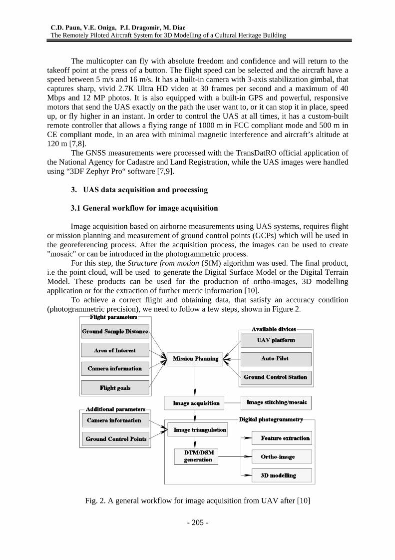
Image acquisition based on airborne measurements using UAS systems, requires flight or mission planning and measurement of ground control points (GCPs) which will be used in the georeferencing process. After the acquisition process, the images can be used to create "mosaic" or can be introduced in the photogrammetric process. For this step, the Structure from motion (SfM) algorithm was used. The final product, i.e the point cloud, will be used to generate the Digital Surface Model or the Digital Terrain Model. These products can be used for the production of ortho-images, 3D modelling application or for the extraction of further metric information [10]. To achieve a correct flight and obtaining data, that satisfy an accuracy condition (photogrammetric precision), we need to follow a few steps, shown in Figure 2.
Fig. 2. A general workflow for image acquisition from UAV after [10]

“1 Decembrie 1918” University of Alba Iulia RevCAD 22/2017
- 206 -
Fig. 3. Image of Barnova Monastery taken with DJI Phantom 3 Standard UAS For this case study, Barnova Monastery, located in Barnova locality, Iasi county was
chosen. This church was build between 1626 - 1629 years, by the Moldavian Voivode Miron Barnovschi- Movila. From 2015, it was included in the list of the National historical monuments and is awaiting funds for restoration, being in a state of decay aggravating.
3.2. Ground control point and image acquisition for Barnova monastery
The accuracy of GPS/INS sensors on-board UAS platforms, is lower than in the
airplanes case. This aspect may derive serious match errors and poor geospatial results [11,12]. For this reasons, they cannot provide a sufficient precision for direct georeferencing process. Therefore, the indirect georeferencing process must be use in order to obtain accurate information, the placing and measuring of GCPs being mandatory. For this case study, the GCPs were made by plexiglass, having the centre marked by the intersection of two black triangles and a metal bold. Five points were placed around the monastery, uniformly distributed, so that they could be visible and not blocked by vegetation (e.g. trees). Then, the coordinates were measured with high accuracy using the GNSS technology, the final coordinates resulting as an average of two determinations [7].
The flight plan is established in a preliminary stage on the office, based on the area of interest. Choosing all the parameters including acquired images resolution, bands coverage (longitudinal and transversal), flight height, has to be made depending on the purpose of the study. In this case, as it is a small area of study, the flight was made at an altitude of about 25 m above the ground the images being acquired in a circular sequence with a resolution of 12 megapixel. For this flight, the manual mode was chosen and it took about 20 minutes to complete. In manual mode, the image overlap and the geometry of acquisition is usually very irregular, while the presence of GNSS/INS devices, together with a navigation system, can guide and improve the acquisition [13]. So, in order to have a complete description of the object, a regular and higher overlap in the image block is required, for this case study the flight being made in a circular mode with the camera axis oriented approximately at 45 degrees to perform oblique acquisition for the facades. Thus, the monastery was photographed all around, being taken 30 images from 30 different camera positions.

C.D. Paun, V.E. Oniga, P.I. Dragomir, M. Diac The Remotely Piloted Aircraft System for 3D Modelling of a Cultural Heritage Building
- 207 -
Fig. 4. The circular flight for oblique images acquisition
As these platforms are strongly influenced by the presence of wind, piloting
capabilities and GNSS/INS quality, all randomly affecting the attitude and location of the platforms during the flight, it is recommended to take as many images as possible with sufficient overlap [7].
3.3 Tridimensional modelling process of the cultural heritage building 3.3.1. Photogrammetric data processing The aim of this study is to acquire and use oblique images for 3D modelling of a
historical monument (monastery) and to analyze the efficiency of 3DF Zephyr software for image processing. Full processing of images is done almost automatically, based on algorithms of photogrammetry and computer vision (CV) and allows to process a large amount of images in a fast and easy way, with a limited influence of the user on the resulted dense point cloud [13]. In other words, this software computes the images alignment based on the SfM algorithm [14], generating the 3D model of the study area as a dense point clouds or mesh surface, the user being able also to generate ortho-images.
SfM involves the use of several images with sufficient overlap, from which the features that will be used for the 3D reconstruction of the scene will be extracted. The input data required for this software, needed in the 3D reconstruction process are only images and a minimal number of GCPs, so it is not necessary knowledge or determining a-prior of interior and exterior orientation parameters of the camera.
The objective 3D reconstruction process includes the following steps: - camera calibration and image orientation - are two very important steps in any process of 3D reconstruction from images. Camera calibration can be done individually i.e. determining its parameters and then, the user can introduce them in the software. Another way is to use control points or introduce the camera orientations. In this stage, the software determines the position and orientation of each image and in the end, the user should have a sparse point cloud as initial 3D product (i.e. calculating the coordinates of features extracted from images). For minimizing the reprojection error of each point, the bundle adjustment process was used; this is a nonlinear minimization procedure that corrects the spatial locations of the point and camera position (orientation angles of each camera - exterior orientation). - extracting dense 3D point cloud- the software returns only 3D points with real 2D matches in the images. The resulted dense point cloud describe the salient corners and features in the

“1 Decembrie 1918” University of Alba Iulia RevCAD 22/2017
- 208 -
former case or the entire surface's shape of the surveyed scene in the latter case. Dense image matching algorithms should be able to extract dense point clouds to define the object's surface and its main geometric discontinuities [10];�-coordinate transformation is performed using ground control points; - mesh and texture generation;
(a) (b)
(c) (d)
(e)
Fig. 5.(a) the 3D model of the monastery represented as a point cloud and the camera positions, (b) detail, (c) the 3D model of the monastery represented as a mesh surface, (d)
detail and (e) the spatial position of GCPs and CPs

C.D. Paun, V.E. Oniga, P.I. Dragomir, M. Diac The Remotely Piloted Aircraft System for 3D Modelling of a Cultural Heritage Building
- 209 -
Using the "3DF Zephyr Pro" software, the 3D model of the monastery, including both facades and the roof, was created. First, the 3D model was represented as a point cloud containing a number of 185 775 points. In Figure 5 a is shown the point cloud from one point of view and in Figure 5 b a detailed view.
The south-east part of the building is obviously disturbed by the presence of trees. An additional survey, only for this part, could be made in a season when the trees have no leafs.
Second, the 3D model was represented as a textured mesh surface, based on the RGB code extracted from UAS images. This step was also performed automatically through interpolating the point cloud, the resulted mesh containing 3.441.083 vertices and 6.876.614 triangles (Fig. 5 c, d) .
3.3.2 Georeferencing the image network results In this case study the indirect georeferencing was used, because the GPS device doesn't offer a geodetic accuracy, the GCPs and CPs determination being necessary. So, a total of five points homogeneous distributed around the monastery (see the Fig. 5 e) have been marked, their coordinates being determined by field measurements using a GNSS rover.
To perform indirect georeferencing, there are basically two ways to proceed, mentioned in [10,7]: (a). import at least 3 GCPs in the bundle adjustment solution and treating them as weighted observations inside the least squares minimization (see table 1). (b). use a free-network approach in the bundle adjustment and apply only at the end of the bundle adjustment a similarity (Helmert) transformation in order to bring the image network results into a desired reference coordinate system. This approach is not rigorous: the solution is sought minimizing the trace of the covariance matrix, introducing the necessary datum with some initial approximations.
Table 1. The coordinates of Ground Control Points determined by GNSS measurements Number of ground
control points X[m] Y[m] Z[m]
1 622751.984 699590.240 142.519 2 622776.817 699600.775 143.355 3 622779.120 699627.323 144.408
The“3DF Zephyr Pro“ software, has the possibility of using more than 3 GCPs, but the results are not much improved, even if it would be used all available GCPs, namely 5 points [7].
For this reason we georeferenced the point cloud using only 3 GCPs, the RMS (Root Mean Square) being 0.012 m.
3.3.3 Accuracy analysis In this section we assess the accuracy of the point cloud automatically generated based on digital images acquired with a low-cost UAS, by measuring and comparing the coordinates of the CPs (Table 2).

“1 Decembrie 1918” University of Alba Iulia RevCAD 22/2017
- 210 -
Table 2. The coordinates of Check Points
No. CPs
Coordinates obtained by GNSS measurements
Coordinates obtained by image measurements
Xr [m] Yr [m] Zr [m] Xi [m] Yi [m] Zi [m] 1 622761.995 699582.383 142.352 622761.980 699582.418 142.331 2 622757.343 699635.751 144.243 622757.369 699635.708 144.253
The coordinates of the check points were measured on oriented images. Then, the
differences between them and the ones measured with precision using the GNSS technology were calculated, using as reference base the coordinates obtained by GNSS measurements.
The Root Mean Square Error (RMSE) was calculated, which is the Euclidian distance between the two coordinate sets for a point calculated with the distance equation [5]:
( ) ( ) ( )2 2 2error r i r i r iRMS X X Y Y Z Z= − + − + − (1)
where: (Xr, Yr, Zr) – the coordinates of a CP obtained by GNSS measurements; (Xi, Yi, Zi) – the coordinates of a CP obtained by image measurements.
The residuals of the 2 CPs coordinates in the process of indirect georeferencing using the minimum number of GCPs, i.e. 3 points, are listed in Table 3.
Table 3. The residuals of georeferencing the point cloud using 3 control points
Number of ground control points
Check point
Differences RMSE [m] ΔX[m] ΔY[m] ΔZ[m]
3 1 0.015 -0.001 -0.021 0.026 2 -0.026 0.003 0.010 0.028
We used only a minimum number of GCPs because the previous research [15, 7] has shown that the increasing the GCPs number did not improve the 3D shape of the surveyed scene. The residuals for the two check point, showed in Table 3, are 2.6 cm for the first point and 2.8 cm for the second one.
The maximum value is recorded on the x-axis direction for the second point, -2.6 cm because the point was located near the edges of the image where errors are higher due to the distortions and the measurement was possible only in three images, compared to other point (measured in 5 images).
4. Conclusions In this paper, the authors presented an overview and the potential of using the existing
low-cost UAS systems, in the process of creating an accurate and detailed 3D model of a Cultural Heritage.

C.D. Paun, V.E. Oniga, P.I. Dragomir, M. Diac The Remotely Piloted Aircraft System for 3D Modelling of a Cultural Heritage Building
- 211 -
Currently, low-cost UAS systems present a great interest for various research, the technology being inexpensive and easy to used, the three-dimensional data being obtained in a relatively short time.
This new technology can be a complement or a substitute method for a terrestrial data acquisition, because the obtained precision, even in the case of low-cost systems, is of centimeters order (currently matches the geodetic precision) and the point cloud automatically generated has a high density, enough to create a 3D model with a high degree of detail for the roof and facades, respectively.
The residuals for the two check points, showed in Table 3, are 2.6 cm for the first point and 2.8 cm for the second one.
The usage of oblique images taken from RPAS, is an efficient tool to survey high building characterized by a specific form, i.e. churches, because the terrestrial data acquisition methods for the entire building (including the roof) are limited, particularly when access is limited. Another advantage lies in getting fast and detailed information with much lower costs compared to other existing methods and technologies.
5. References 1. Neitzel F., Klonowski J. - Mobile 3D mapping with a low-cost UAV system. International
Archives of the Photogrammetry, Remote Sensing and Spatial Information Sciences, Vol. XXXVIII-1/C22 UAV-g, Conference on Unmanned Aerial Vehicle in Geomatics, Zurich, Switzerland, 2011.
2. Aicardi I., Chiabrando F., Grasso N., Lingua A. M., Noardo F., Spanò A. UAV photogrammetry with oblique images: first analysis on data acquisition and processing, The International Archives of the Photogrammetry, Remote Sensing and Spatial Information Sciences, Volume XLI-B1, XXIII ISPRS Congress, Prague, Czech Republic, 2016.
3. Wefelscheid C., Hansch R., Hellwich O. - Three-dimensional building reconstruction using images obtained by unmanned aerial vehicles. International Archives of the Photogrammetry, Remote Sensing and Spatial Information Sciences, Vol. XXXVIII-1/C22 UAV-g, Conference on Unmanned Aerial Vehicle in Geomatics, Switzerland, 2011.
4. Nakano K., Suzuki H., Tamino T., Chikatsu H. - On fundamental evaluation using UAV imagery and 3D modeling software, The International Archives of the Photogrammetry, Remote Sensing and Spatial Information Sciences, Volume XLI-B1, XXIII ISPRS Congress, Prague, Czech Republic, 2016.
5. Adami A., Chiarini S., Cremonesi S., Fregonese L., Taffurelli L., Valente M.V. The survey of cultural heritage after an earthquake: the case of Emilia – Lombardia in 2012. The International Archives of the Photogrammetry, Remote Sensing and Spatial Information Sciences, Volume XLI-B5, XXIII ISPRS Congress, Prague, Czech Republic, 2016.
6. Lo Brutto M., Garraffa A., Meli P. UAV platforms for cultural heritage survey: first results, ISPRS Annals of the Photogrammetry, Remote Sensing and Spatial Information Sciences, Volume II-5, 2014.
7. Oniga E., Chirila C., Macovei M. Low-cost unmanned aerial systems in cadastral applications. SGEM2016 Conference Proceedings, ISBN 978-619-7105-59-9 / ISSN 1314-2704, June 28 - July 6, Book2 Vol. 2, 947-954 pp, 2016.
8. Information on http://www.dji.com/product/phantom-3-standard 9. Information on http://www.3dflow.net

“1 Decembrie 1918” University of Alba Iulia RevCAD 22/2017
- 212 -
10. Nex F, Remondino F., UAV for 3D mapping applications: a review. Applied Geomatics 6(1): 1-15, 2013, CrossRef.
11. Rhee S., Kim T. Dense 3d point cloud generation from UAV images from image matching and global optimization. The International Archives of the Photogrammetry, Remote Sensing and Spatial Information Sciences, Volume XLI-B1, XXIII ISPRS Congress, Prague, Czech Republic, 2016.
12. Gerke, M. and Przybilla, H.-J. Accuracy Analysis of Photogrammetric UAV Image Blocks: Influence of Onboard RTKGNSS and Cross Flight Patterns. Photogrammetrie – Fernerkundung – Geoinformation (PFG), 17-30, 2016.
13. Aicardi I., Chiabrando F., Grasso N., Lingua A. M., Noardo F., Spanò A. UAV photogrammetry with oblique images: first analysis on data acquisition and processing, The International Archives of the Photogrammetry, Remote Sensing and Spatial Information Sciences, Volume XLI-B1, XXIII ISPRS Congress, Prague, Czech Republic, 2016.
14. Westoby M.J. , Brasington J. , Glasser N.F. , Hambrey M.J. , Reynolds J.M.. ‘Structure-from-Motion’ photogrammetry: A low-cost, effective tool for geoscience applications. Elsevier, Geomorphology 179, 300–31, 2012.
15. Tahar K.N. An evaluation on different number of ground control points in Unmanned Aerial Vehicle photogrammetric block. International Archives of the Photogrammetry, Remote Sensing and Spatial Information Sciences, Volume XL-2/W2, 2013.