THE REMARKABLE AND UNIQUE TATE MODERN EXTENSION
40
THE REMARKABLE AND UNIQUE TATE MODERN EXTENSION WWW.RAMBOLL.CO.UK
Transcript of THE REMARKABLE AND UNIQUE TATE MODERN EXTENSION

THE REMARKABLE AND UNIQUE TATE MODERN EXTENSIONWWW.RAMBOLL.CO.UK


“The Tate Modern extension is a genuinely unique and iconic building that required stand-out engineering solutions. I am very proud that Ramboll played such a critical role in bringing to life a visionary building that will leave a long lasting legacy for the city of London”
Jens-Peter Saul, Ramboll Group CEO.
On 17th June 2016 the Tate Modern extension was officially opened. Explore more about what has made this project one of the UK’s most remarkable and unique buildings and Ramboll’s intrinsic involvement.
Imag
e: Iw
an B
aan.

2
THE TATE MODERN EXTENSION
The Tate Modern extension is a truly ground-breaking building that pushes the boundaries of modern design and engineering. From the one-of-a-kind geometric structure to the striking brick façade, every facet of this building has been planned and engineered with staggering precision. It is a fitting extension to one of the world’s leading galleries, and will ensure that the art exhibited by Tate Modern can continue to enthral future generations.
GOOD DESIGN TAKES TIME, ENERGY AND DEDICATION TO SUCCEED — AS EXEMPLIFIED IN TATE MODERN’S EXTENSION
01 Tate Modern brick façade 336,000 bricks create the awe-inspiring façade of Tate Modern’s extension. 02 Tate Modern - Boulevard stairs Four distinctive boulevard stairs form part of Tate Modern’s visitor circulation strategy.
03 Showing the one-of-a-kind geometric structure.
01
02

3
SERVICES PROVIDED BY RAMBOLL:
• Structural engineering• Façade engineering • Civil engineering• Geoenvironmental consulting• Geotechnical engineering• Flood management
03

4
Standing at 10 storeys tall, the new Tate Modern extension will provide an enhanced visitor experience. Its additional spaces will display a greater variety of artworks and show more artists from around the world. This will enable Tate Modern to present an increasingly international view of modern and contemporary art.
The extension has enabled an increased display space of 60%, which is hugely welcome as visitor numbers since its opening in 2000 exceeded all expectations, averaging five million annually.
In addition, the rebuilding of part of the existing Switch House and the relocation of its switchgear has reclaimed three additional 18m-span floors of gallery space.
Tate Modern’s £260m extension also includes additional learning spaces, retail areas, offices and a café.
ACCOMMODATING GROWING VISITOR NUMBERS
01 Tate ModernAn awe-inspiring building, a testament to the world’s most visited museum of modern art.
02 Tate ModernDisplay space has been increased by 60% following Tate Modern’s extension. Image: Kai Richter.
03 Tate’s visitors The extension will provide an enhanced visitor experience.
With 60% more display space, visitor numbers to Tate Modern have exceeded all expectations since 2000.

5
03
01 02

6
THE NEW BUILDING
“It is a real privilege to have played such a pivotal role on the Tate Modern extension. From threading the building’s foundations around the oil tanks to defining the structure and the building envelope, we’ve realised the architectural vision and helped to create an iconic building that reflects the status of Tate Modern’s brand.”
Martin Burden, Director Ramboll.
01
01 Super structureThe uniquely shaped building, positioned on top of the three disused oil tanks.
02 Tate ModernThe distinctive perforated brick façade ties the extension together with the original building.
The Tate Modern extension has been built on top of its three disused oil tanks. Positioned in a clover leaf shape, each of these awe-inspiring structures spans approximately 30m and located 9m below ground. Two of the three oil tanks create new unique gallery spaces for large-scale artists’ installations, performances and films.
Rising above the oil tanks is the new building’s complex form, with an irregular ground plan largely dictated by the constraints of the site. Rising in a truncated twisting pyramid, the building has sharp corners and inward creases, breaking the façade into a series of interesting geometries — a response to the rectilinear monumentality of the power station.
Tying the buildings together visually are the external materials, where the brickwork forms a sloping, perforated screen that encases the building. This is punctuated by a series of windows. The two buildings connect at levels 00 and 01, and at level 04, via a new link bridge. At the double-height top floor, glazed curtain-walling is set back from the façade to form a roof terrace with 360o views of the River Thames, St Paul’s Cathedral and London’s skyline.
Appointed by the Trustees of Tate, Ramboll provided: structural, geotechnical, civil, façade engineering and environmental consultancy for the project. Ramboll has collaborated and coordinated with the client, design and construction teams in the delivery of Tate’s vision and Herzog & de Meuron’s architectural interpretation for Tate Modern’s extension, a truly multi-disciplinary collective effort.

7
STAGGERING STATISTICS:
• 336,000 bricks of 212 types laid in 18 months
• 11,500 corbels in 400 types• 1,700 panes of glass• 26m high link bridge• Tolerances of +/-2mm
maintained over the 65m high façade
02

8
FROM THE GROUND UP
02
01
Ramboll’s work on the new Tate Modern extension spans a multitude of disciplines. Early works involved geoenvironmental ground investigations. With a rich industrial heritage, Tate Modern is located on the site of the former Bankside Power Station. The gallery is in close proximity to the Thames and surrounding sensitive receptors.
Assessment of soil conditions, the ground water and ground gas regimes formed a baseline for methodology for all the groundwork going forward. This resulted in subsequent recommendations of mitigation by design and construction, minimising the amount of remedial works that had to be undertaken.
A number of working procedures were adopted during the ground work phase. Ramboll were then further commissioned to have an ongoing watching brief to monitor the ground conditions, to ensure there was no mobilisation of any contaminants.
01 Bankside Power Station in 1968Image: Fox Photos/Hulton Archive/Getty Images.
02 Oil tanksGround contamination risks were assessed and a strategy designed to minimise impact on construction.
03 Tate ModernTate Modern on the site of the former Bankside Power Station.

9
03
STRATEGIES FOR MITIGATION BY DESIGN AND CONSTRUCTION MINIMISED REMEDIAL WORKS

10
TYING THE TWO BUILDINGS’ FOUNDATIONS TOGETHER
With the Switch House sharing its foundations with the existing Turbine Hall and the new building’s tower oversailing the Switch House, settlement was a key consideration for the Ramboll geotechnical team, especially with the Turbine Hall glass roof. Movement posed a critical issue and was a key driver in the development of the foundation design for the new building.
Extensive work went into tying the foundations together. Access was limited at this stage, as the Switch House piles were installed prior to any demolition on site. The architectural intent for the original oil tanks was to remain in their current condition, in order to recognise the industrial heritage of the site. Movement of the tank walls was closely monitored during the works, to ensure that they could be converted in the future into a highly-controlled environment of art spaces.
01 Foundation designThe foundation design for Tate Modern’s extension ties the new building together with the existing Switch House and Turbine Hall, minimising movement during construction.
02 Turbine Hall and Switch HouseTate Modern’s extension integrates with the Turbine Hall and Switch House and sits on top of the 3 existing oil tanks.
03 Western elevationTate Modern western elevation.
01
02

11
03
The industrial heritage of the site, coupled with tying the foundations together between the Turbine Hall and the new building’s tower, required meticulous and insightful engineering from Ramboll’s geotechnical team.

12
CHALLENGING GEOMETRY
This unique building has one-of-a-kind geometry and a remarkable brick façade. Every facet of the building’s design has had to be planned and coordinated with staggering precision.
Its distinctive and complex geometry impacted many aspects of the building, including the brick arrangement, the windows and precast façade panels, the internal structure and the scaffold.
The truncated twisting pyramid structure with its sloping elevations, applies large horizontal forces that create a twisting corkscrew effect on the structure. To overcome this effect, Ramboll’s structural engineers designed two internal cores and carefully coordinated their location with the architecture and services strategy.
This external arrangement creates an interesting array of internal spaces. The building’s sloping façade means that every floor offers something unique, without a single right angle, while four feature staircases provide vast cathedral-like public spaces.
The lower floors of the new building and the partially rebuilt Switch House floors boast incredibly large rooms with spans of up to 18m.
Achieving these clear spans, whilst being able to accommodate the essential loading conditions for the gallery, was very important for Tate Modern’s displays.
01 Northern elevationNorthern sloping elevation that overlooks the Turbine Hall.
02 Unique geometryThe brick façade was designed with staggering precision around the unique geometry of the building. Image: Kai Richter.
03 Structure internal coresTwo internal cores overcome large horizontal forces from the twisting pyramid structure.
02
01

13
03

CREATING AN ICONIC ADDITION TO THE LONDON SKYLINE


16
Braced by its two internal cores, the concrete frame to the tower has been carefully coordinated with the remaining basement structure of the oil stores and terrace to establish a relationship with the raw character of the existing industrial architecture. The main structural scheme comprises both reinforced concrete and steel-framed construction. Much of the existing basement space has been preserved, with openings formed in the large existing retaining wall to create new through access routes to Tate Modern’s Turbine Hall.
At ground level, the frame emerges out of the concrete underworld in the form of a faceted pyramid. Deep transfer beams, both internally and at the building’s perimeter, facilitate a change in geometry and provide a base for the tower structure to ascend.
The two large internal reinforced concrete cores were essentially designed and constructed in jump form as solid boxes, with localised openings and exposed surfaces to create the aesthetically pleasing finish that was so critical.
Ramboll’s passion for design is seen throughout this building, with countless numbers of concrete options explored for the exposed areas, to be sure of the best end result.
The final concrete solution specified was 40% GGBS; a grade which not only ensures a light and smooth finish with sharp edges, but also has lower CO2 , resulting in a lower carbon footprint.
MAINTAINING ITS RAW INDUSTRIAL CHARACTER
01 The towerThe tower structure, comprised of reinforced concrete and steel frame.
02 Triple height atriumTriple height raking columns form the atrium space.
01

17
02

18
A STRUCTURAL DESIGN THAT EMBRACES THE BUILDING’S MULTIFACETED NEEDS
01 Stunning viewsThe open terrace on level 10 provides spectacular views across London.
02 Careful coordinationServices carefully integrated within the precast concrete soffits.
03 Slender columnsSlender precast perimeter columns support the precast cladding panels, glazing and brickwork.
The very limited number of internal columns (only three on the lower floors and six above level 06) are strategically positioned to maximise the internal spans, and emphasize the internal spaces. Meanwhile, the continuous precast perimeter columns crank to form the ‘creases’ in the envelope of the building. Containing a core of structural steel at critical locations to provide slenderness, the precast perimeter columns are cruciform in profile, with ‘arms’ to support the precast cladding panels, glazing and brickwork.
Walls were designed to coordinate with the services design, ensuring that all cables were cast into the walls during construction and none were left exposed.
Floor plates are formed of long span in-situ concrete ribs, which support both the concrete floor plate and the precast concrete soffit planks. The services are located in the raised floor, dropping through carefully coordinated holes in the rib beams into the service slots below and cast-in cooling coils within the precast concrete soffit panels.
On level 10 an open terrace is located around the perimeter of the building. The “open” terrace, with hanging perimeter columns to the north elevation, is achieved by spanning deep steel beams from the main core and cantilevering from the central and perimeter columns where required.
In the Switch House, the existing steel frame was removed above level 03. A new steel frame now bridges the resulting void between the reinforced concrete tower structure and new steel columns adjacent to the existing Turbine Hall columns, providing 18m clear spans to the galleries. This is tied to the concrete frame and both structures are founded on piled foundations to ensure continuity through the two buildings. A storey-height truss was required at the level 02 west elevation to span over UK Power Network’s assets and long span transfer beams were installed to achieve the entrance openings.

19
03
0201

20
01

21
The northern elevation of the tower oversails the Switch House at level 05. With no columns allowed to enter the gallery space below, it required careful structural design of a transfer structure and jacking system, and close monitoring during construction to limit movements to +/-2mm.
At level 05 of the Switch House, the sloping north elevation of the tower meets the roof of the level 04 gallery. With no possibility of continuing the north elevation into the gallery space, a 1.8m deep spreader beam was installed. This distributes the loads from the perimeter structure into the roof beams which, in turn, transfer the load to the core and northern Switch House columns.
In order to distribute the loads effectively, whilst not allowing any deflection to occur, the spreader beam was supported on a series of 16 jacks. These were closely monitored during the construction of the north elevation, and jacking operations undertaken at strategic times to minimise impact on the construction above. Once the final brick was installed, the jacks were grouted with maximum differential movement between roof beams having been limited to the required 2mm.
To achieve the tolerances required for installation of the glazing and brickwork it was essential that the deflection of the structural frame to the perimeter of both the tower and Switch House buildings was limited. Although complicated by the geometry of the tower and the various types of transfer structures, deflection limits of 1 in 1000 were achieved.
01 Northern elevationViews of the Turbine Hall glass roof from level 05 of the original building.
02 North and south lift coresView between the north and south lift cores which provide stability to the building.
02

The unique brick façade acts as a rain screen and is the architectural wonder of the building.
22
A UNIQUE BRICK FAÇADE
Truly an architectural wonder, the building’s unique perforated brick façade envelopes the structural frame, acting as a rain screen. The corners and creases are column free, emphasising the continuity of the surface, whilst providing “open views” to the exterior.
In total 336,000 bricks in 212 different types were installed between August 2014 and February 2016, using a new system that could be installed in ‘all-weather’.
The architectural intention was for the wall to be ‘movement joint’ free and this was a key consideration in developing the most suitable brickwork system. Accommodation of the relevant tolerances in the façade, manufacture and installation were critical to achieving a successful building envelope. 3D setting out tools were invented for the project, to ensure that tolerances of +/-2mm were maintained over the 65m high façade.
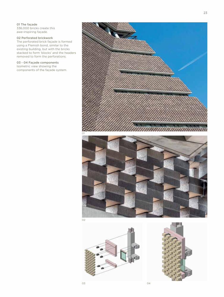
The masonry selected for the façade was carefully specified to ensure its long term behaviour and performance. The brickwork underwent three rounds of testing. The specified bricks are 215mm square and 69mm high engineering bricks and had varying colours in order to be similar to the existing building. The brick pattern is based on a Flemish bond, also similar to the existing building, with bricks stacked in pairs and prebonded with polymerised mortar, creating a block of 215 x 215 x 145mm high, and the header bricks omitted, creating a ‘perforated’ screen of bricks.
23
0403
02
01
01 The façade336,000 bricks create this awe-inspiring façade.
02 Perforated brickworkThe perforated brick façade is formed using a Flemish bond, similar to the existing building, but with the bricks stacked to form ‘blocks’ and the headers removed to form the perforations.
03 - 04 Façade componentsIsometric view showing the components of the façade system.

Construction of the brick façade is as unique as the structure, withthe bricks being used in a way never previously thought possible.
24
THE BRICKS
Construction of the brick façade is as unique as the structure, with the bricks being used in a way never previously thought possible and acting as a veil over the structure. On site the blocks were connected together using elastomeric joints, stainless steel pins and a resin joint. The façade works in a series of arches to allow the brickwork to move horizontally and vertically and is restrained back to the façade with 11,500 corbels made up of 400 types.
Corbels are an integral part of the scheme. Supported by the internal perimeter structure and floor beams, precast panels provide support for the corbels and brickwork and provide a thermal and moisture barrier to the building. Sitting in empty header spots in the masonry, the corbels support the brickwork skin and offer a mechanism for reducing general frame tolerances as an interface to the more refined brickwork.
Solid brickwork is used on the lower levels. The sloping brickwork is achieved by offsetting blocks at each course to create the correct overall slope. In the vertical façades the double courses are also offset in and out of the wall plane to give a texture similar to the sloped façades.
There are 5 distinct ‘types’ of brickwork:1. Vertical perforated – stepped
brick2. Sloping perforated – stepped
brick3. Sloping solid – flush brick4. Vertical solid – flush brick5. Vertical solid – stepped brick
At the corners and creases additional ‘special’ blocks and site cut standard size blocks were required to suit the interface between adjoining brick elevations. A procedure was developed to maintain a consistent method of support to the brickwork and to also meet the required irregular visual appearance.

25
01
02
03
01 Prebonded brickworkThe bricks were stacked in pairs and prebonded with polymerised mortar to create blocks.
02 All weather constructionOn site the blocks were connected together using elastomeric joints, stainless steel pins and a resin joint.
03 Full scale mock-upThe unique façade underwent three rounds of testing, including a full scale mock-up. Image: Ramboll.
It would have taken five years to complete the brickwork, but the solutions designed for the Tate Modern extension enabled construction in all weather, reducing the time frame to just 18 months.

The structure links the new and existing gallery spaces and provides a unique and fabulous new viewing point for the exhibitions below.
26
Connecting the Boiler House to the Switch House is the Turbine Hall link bridge, installed at a high level, 26m above the Turbine Hall floor and amid the existing roof trusses. The 25m long bridge connects the Boiler House galleries of the original Tate Modern building to the new Switch House galleries and forms part of the overall circulation strategy and visitor experience of Tate Modern.
The bridge deck slopes to make up the difference in levels between the two buildings and is designed as an exposed polished concrete slab to complement the surface finish of the bridge and Turbine Hall floor below.
Substantial elements of the bridge were prefabricated off-site. Together with the construction team, Ramboll developed an installation sequence employing a suspended scaffold screen and runway. Utilising the existing Turbine Hall roof trusses, the primary structural elements were winched, via strand jacks anchored in the Switch House, launching the bridge across the Turbine Hall, while supported on bearings at either end. Once in position, the concrete slab was cast, and power-floated to give it a highly polished finish.
This method of construction maximised off-site fabrication and saved on significant temporary works having to be constructed within the Turbine Hall. It allowed the bridge to be constructed and installed in an efficient manner, minimising the programme time.
The completed structure sits almost unnoticed, complementing the existing roof trusses and providing not only a pivotal link between the new and existing gallery spaces, but also a stunning new viewing point for the exhibitions below.
A BRIDGE TO LINK THE BUILDINGS
01 The link bridgeLinking the gallery spaces, the bridge provides impressive views of the Turbine Hall.

27
01

28
NAVIGATING THE GALLERIES
Far more than just a means of getting to different floors, four individually unique boulevard stairs are wide and deep, creating a place where people can circulate and connect, enhancing their overall experience.
With their distinct curved geometry, the stairs from levels 00 to 04 interconnect with all the elements of the structural frame – the existing structure, the floor plates, cores and perimeter structure. They typically span as distinct U-shaped elements, with the vertical sides forming the balustrades. The soffits are formed as continuous planes, with void formers minimising weight, whilst achieving the architectural shape. Between levels 05 and 10, the stairs wrap around and cantilever from a central spine wall supported off the core below.
The design of the stairs and supports, along with their construction sequence, were carefully considered to accommodate the complicated interfaces, the geometrical challenges and the exposed concrete. In combination with the building’s layout, their positioning enables visitors to view each floor with ease.
01 Level 01 to level 04 staircaseImpressive spiral stairs aid the overall circulation strategy for Tate Modern.
02 Level 00 to level 01 staircase This spatial stair interfaces with the existing basement structure and leads visitors from the oil tanks up to the Switch House.
03 Level 02 to level 04 staircaseWide sweeping stairs interface with both the perimeter structure and internal core.
02
01

29
03

VIEWS FROM THE BUILDING
Looking out from within the new Tate Modern extension, it is difficult to comprehend the level of complexity involved in designing the windows. With five different inclinations, the building’s creases and corners resulted in 60 different glass heights across its nearly 1,700 glass panes, spanning up to 29 rows of windows and glazed screens scattered over the whole envelope.
Precision was absolutely critical, with all glass in the corners and creases designed in 3D and cut to shape. Even non-exposed bracketry and window support systems were designed using the structure’s overall 3D model. This resulted in a high level of accuracy from the start of the design, enabling consideration of complex building movements and load paths, plus special precision during fabrication and assembly within the concrete exterior face.
Approximately 35% of the windows are unscreened, with the remaining 65% behind the perforated brick façade, creating transparency, which allows light to flood in. At night, when lit, the building looks stunning, with light glowing through the brickwork.
High performance extra-clear, special UV and anti-fade specification glazing has been installed to help protect Tate Modern’s art displays from UV and, together with the brickwork brise soleil, minimise solar gain.
The design of the window system also negates the need for a building maintenance unit, with the majority of the windows accessible for cleaning from the interior.
The Switch House galleries boast large vertical glass slots and a large roof light, allowing natural daylight to flood into the vast spaces without compromising the delicate art displays.
At level 10 the building is crowned by an exceptional venue space. At the double-height top floor, glazed curtain walling is set back from the façade to form a roof terrace, with breathtaking 360° view of The Thames, St Paul’s, The Shard and the City beyond.
30

0403
02
01
01 A high level of transparency1,700 panes of glass span 29 rows of windows, allowing light to flood into the building.
02 Complex geometryA high level of accuracy was required in designing the building’s windows, to accommodate the building’s complex geometry.
03 Fascinating spaces and viewsVisitors can experience spectacular views across London. Image: Kai Richter.
04 Stunning dappled effectThe perforated brick façade creates a stunning dappled effect as light floods into the building. Image: Kai Richter.
31

32
DRAINAGE AND FLOOD MANAGEMENT
A drainage and flood management strategy was designed to minimise both the risk of flooding and the impact to the existing downstream sewer system. The strategy was devised following consultation with the Environment Agency and was based on an agreement on the proposed discharge rate from the development site, into the existing Thames Water’s combined sewer.
In order to minimise the impact to the existing downstream drainage network, the proposed surface water discharge rate has been reduced by 80% from that of the existing surface water runoff rates, including and up to 1 in 100 year storm events. To minimise the risk of flooding and to comply with Planning Policy Statement 25 (National Planning Policy Framework), an additional 20% allowance in the rainfall intensities due to climate change, was incorporated into the design.
Runoff from the building façade is collected via channel drainage and discharged into the below ground drainage network. Considering the unique angled face of the façade, the design of a linear channel surrounding the new building was especially challenging and was developed with a leading manufacturer in order to achieve a unique and bespoke design.
Below ground attenuation tanks have been designed and installed at four locations across the site with one soakaway tank within the site boundary, providing the required attenuation volume.
The attenuation tanks are made of light geocellular units with a honeycomb structure, providing a void ratio of 95% for attenuation of surface water within the tanks. Flow control device hydrobrakes were also designed to restrict the flow at agreed discharge rates.
The site’s industrial heritage, coupled with a myriad of underground services, made the installation of the below ground attenuation tanks difficult. Ramboll implemented solutions that included the uneven orientation of tanks and the bridging over of existing pipelines.

33
01
01 Public realm spacePublic realm space has been maximised, including the pedestrianisation of Sumner Street.
NEW PUBLIC REALM
As part of the overall regeneration of the South Bank area, the public realm space has been maximised to create increased trade for local businesses, and roads around the Tate Modern extension have been adapted.
Part of Sumner Street, previously an existing Vehicle Access Road, has been partly blocked off and converted into a shared surface carriageway to provide more space
for pedestrians and cyclists with occasional access for maintenance vehicles. Holland Street and the south of Sumner Street have been converted from a two-way system into a one-way system for vehicular traffic, including provision for a cycle route.

34
THE RAMBOLL TEAM
Adam HodgesAlexander LivingstonAlastair McGregorAndrew BatchelorAnn GordonAnton SawickiAstrid GunnBradley WelshCharles McBeathCharmian TamChris MillsCiaran MalikCillian RyanDaniel DeanDaniel NiziolekDavid MerrickEddie JumpEdward James GrantElina KallialaElizabeth BismutGraham EdgeGuy CollingwoodIan AbleyIan LanghamIan Morton
Ian O’KeeffeIan WalkerJacky NgJames NormanJames SollyJames TearleJeremy FosterJonathan LouisKai RichterLinnea EngemannLisa-Marie FernandesMadi BolourchiMaria Eugenia Sanchez VaamondeMark WhitbyMartha DallynMartin BurdenMatthew PhillipsMiriam ButtiMohsen VaziriMonika Sokal Naoki WoodwardNeesha GopalNicholas James FarnanNicholas O’BrienNiki Dubber
Nishma AgarwalOsric FortonPhilip WilkinsonPierre-Edouard PichotRaisa LaluiRiccardo PedroniRobert GodboldSergio de GaetanoSimon CornessSimon GrovesSimon SmithSteve CanadineSujal ParikhSuria JonesSylwia SkrzypTatiana PattenTim SholerTony McManusVicky PottsWill StevensWojtek KatnyYanchee LauYvette Park
THE TATE MODERN EXTENSION
All drawings courtesy of Ramboll, unless otherwise stated.
All images courtesy of Daniel Shearing, unless otherwise stated.

35
Nishma AgarwalOsric FortonPhilip WilkinsonPierre-Edouard PichotRaisa LaluiRiccardo PedroniRobert GodboldSergio de GaetanoSimon CornessSimon GrovesSimon SmithSteve CanadineSujal ParikhSuria JonesSylwia SkrzypTatiana PattenTim SholerTony McManusVicky PottsWill StevensWojtek KatnyYanchee LauYvette Park
Ramboll would like to extend special thanks to the entire project team, whose collaboration, focus and dedication has seen the realisation of this truly remarkable and unique building.
It will not only leave a lasting legacy for Tate, its visitors and the artists who perform and display their work, it will also remain in the hearts of those who have been involved in its design and construction, for whom working on such an icon has been a dream come true.
THE PROJECT TEAM
Client Trustees of Tate Principal contractor Mace Architect Herzog & de Meuron Structural engineers Ramboll Geotechnical engineers RambollCivil engineers RambollFaçade engineers Ramboll Environmental consultants RambollMEP engineers Max Fordham Project manager Gardiner & Theobald Landscape architect Vogt Cost consultants Aecom Quantity surveyor Davis Langdon Frame contractors Byrne Bros Brick and scaffold contractors Swift Brickwork Contractors External works contractor Maylim External glazing Seele Sub structure contractor McGeeSteelwork contractor part 1 BourneSteelwork contractor part 2 Severfield (UK) LtdUnderground drainage contractor P.J Carey (Contractors) LtdPerimeter structure and Loveld precast concrete cladding contractor