
The Relation between Science and Innovation
60
1 The Relation between Science and Innovation Toyota Motor Corp. Battery Research Lab. Hideki Iba
Transcript of The Relation between Science and Innovation

1
The Relation between Science and Innovation
Toyota Motor Corp. Battery Research Lab. Hideki Iba
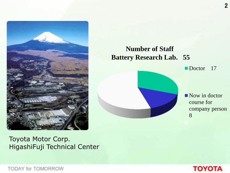
2
Number of Staff
Battery Research Lab. 55
Doctor 17
Now in doctor
course for
company person
8
Toyota Motor Corp. HigashiFuji Technical Center

3


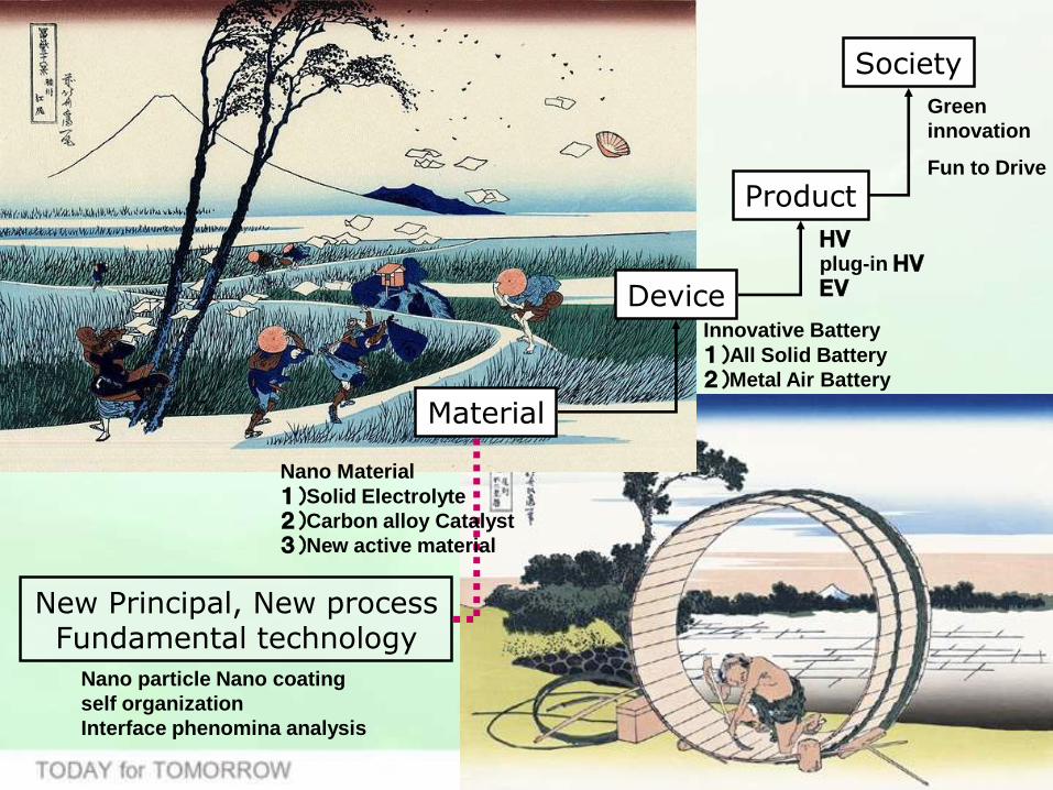
New Principal, New process Fundamental technology
Material
Product
Device
Society
Green
innovation
Fun to Drive
HV
plug-in HV
EV
Innovative Battery
1)All Solid Battery
2)Metal Air Battery
Nano Material
1)Solid Electrolyte
2)Carbon alloy Catalyst
3)New active material
Nano particle Nano coating
self organization
Interface phenomina analysis


電子 電子
Cathode(LiCoO2) Anode(Carbon)
3~4V
Liquid Electrolyte
New Principal, New process Fundamental technology
Material
Product
Device
Society
Green
innovation
Fun to Drive
HV
plug-in HV
EV
Innovative Battery
1)All Solid Battery
2)Metal Air Battery
Nano Material
1)Solid Electrolyte
2)Carbon alloy Catalyst
3)New active material
Nano particle Nano coating
self organization
Interface phenomina analysis

11
560km (350m i les)
Osaka Tokyo
Start Goal


15
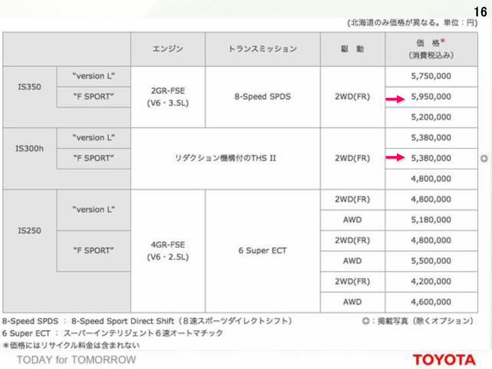
16
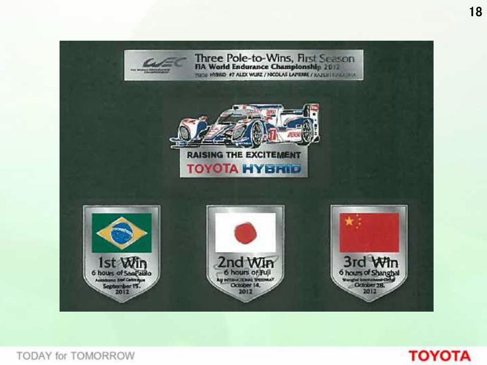
18

19
標高差1,439m 距離19.99km コーナー数156 平均勾配7%

New Principal, New process Fundamental technology
Material
Product
Device
Society
Green
innovation
Fun to Drive
HV
plug-in HV
EV
Innovative Battery
1)All Solid Battery
2)Metal Air Battery
Nano Material
1)Solid Electrolyte
2)Carbon alloy Catalyst
3)New active material
Nano particle Nano coating
self organization
Interface phenomina analysis

21
10 100 1000 10000
’10
’20
’15
NiMH battery
1000
2000
4000
6000
8000
10000
Limit of conventional
batteries
All Solid
Battery
Metal Air
Battery
Sakic
hi
Batt
ery
Po
we
r D
en
sit
y (W/ℓ
)
Volumetric Energy Density (Wh/ℓ)Mile Range

22
0 100 200
出力密度
0
2000
4000
6000
[W/L]
0 800 300 400
ニッケル水素電池 Nickel-metal hydride battery
500 600 700
8000
2015年
2020年
2030年
2025年
リチウムイオン電池 Lithium-ion battery
全固体電池
リチウム空気電池 Lithium-air battery
高出力型 (HV用)
高容量型(EV、PHV用)
エネルギー密度 [Wh/L]
1000 900
現状(コインサイズ)
現状
Po
we
r d
en
sity
High power type
High capacity type (for EV,PHV use)
All-solid-state battery
Current condition (coin size)
Current condition
Energy density
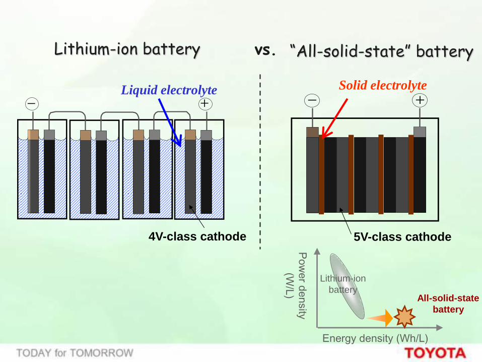
Liquid electrolyte Solid electrolyte
- + - +
“All-solid-state” battery Lithium-ion battery vs.
4V-class cathode 5V-class cathode
Pow
er d
ensity
(W/L
)
Energy density (Wh/L)
Lithium-ion
battery All-solid-state
battery

24
http://techon.nikkeibp.co.jp/

25
26
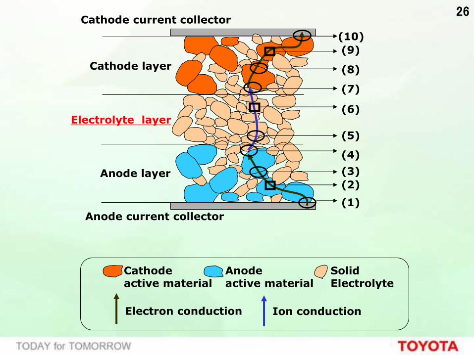
Cathode layer
Electrolyte layer
Anode layer
Anode current collector
Cathode current collector
(1)
(2)
(3)
(4)
(5)
(6)
(8)
(9)
(7)
(10)
Electron conduction Ion conduction
Cathode active material
Anode active material
Solid Electrolyte
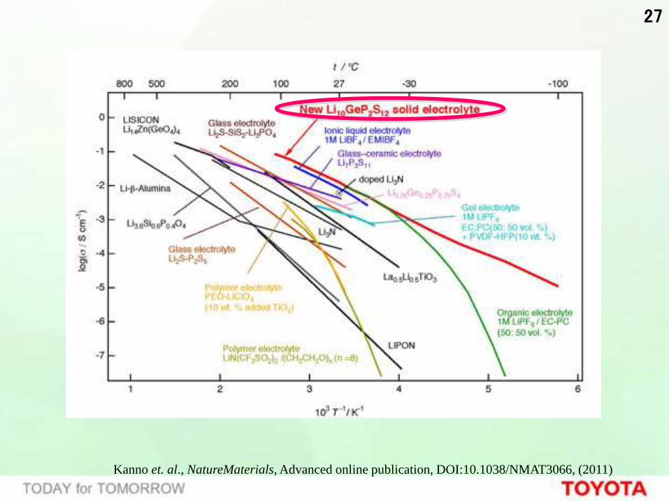
27
Kanno et. al., NatureMaterials, Advanced online publication, DOI:10.1038/NMAT3066, (2011)

28
Kanno et. al., NatureMaterials, Advanced online publication, DOI:10.1038/NMAT3066, (2011)
(Ge,P)S4
PS4
LiS6
Moving Li ion
a b
c a
b
29
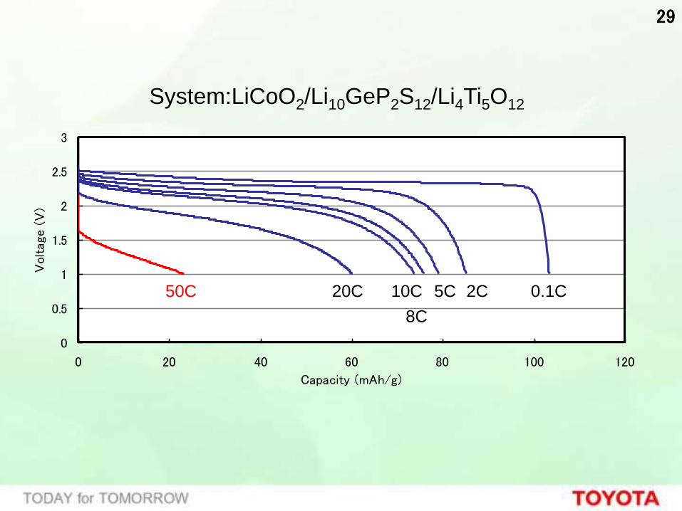
System:LiCoO2/Li10GeP2S12/Li4Ti5O12
0
0.5
1
1.5
2
2.5
3
0 20 40 60 80 100 120
Capacity (mAh/g)
Vol
tage
(V
)
0.1C 2C 5C
8C
10C 50C 20C
30
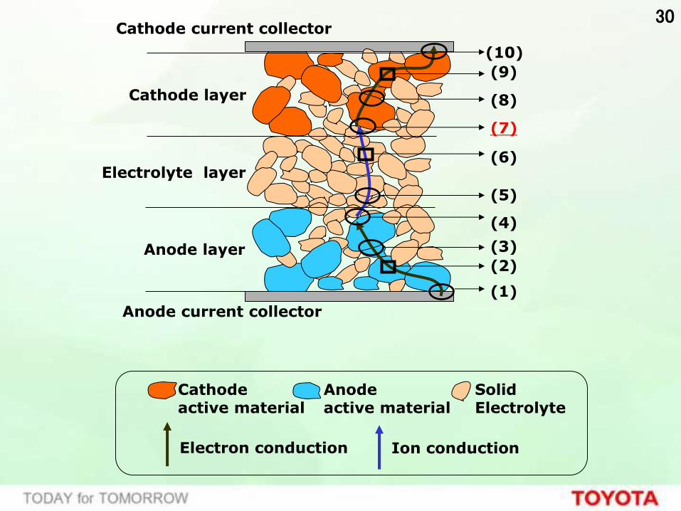
Cathode layer
Electrolyte layer
Anode layer
Anode current collector
Cathode current collector
(1)
(2)
(3)
(4)
(5)
(6)
(8)
(9)
(7)
(10)
Electron conduction Ion conduction
Cathode active material
Anode active material
Solid Electrolyte
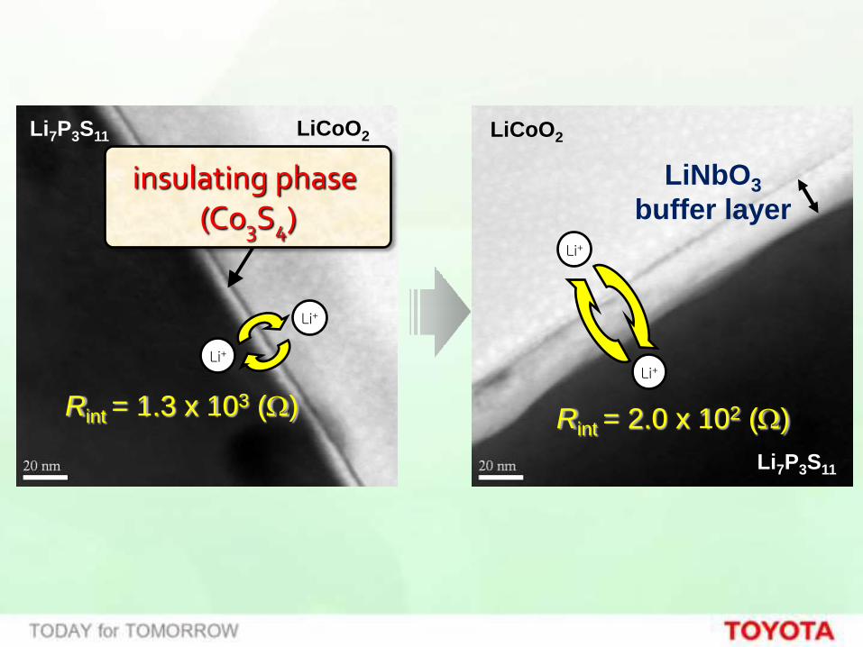
Rint = 1.3 x 10³ (W) Rint = 2.0 x 10² (W)
LiCoO2 Li7P3S11
Li+
Li+
Li7P3S11
LiCoO2
LiNbO3
buffer layer
Li+
Li+
insulating phase (Co3S4)

32
LiPON
LiCr 0 . 0 5 Ni0 . 4 5 Mn1 . 45O 4
(LNM)
Li
C/Ti/Pt
6 0 nm
2 .5 m m
5 .0 m m
BaTiO3 (10nm)(a)
200 nm
(b)
-0.6
-0.4
-0.2
0
0.2
0.4
0.6
0.8
3.0 3.5 4.0 4.5 5.0 5.5
E / (V vs. Li/Li+)
I /
μA
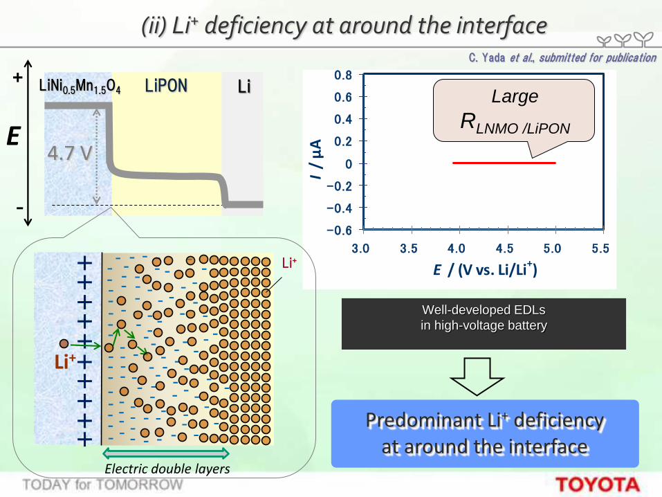
(ii) Li+ deficiency at around the interface
C. Yada et al., submitted for publication
E
+
-
LiPON Li LiNi0.5Mn1.5O4
4.7 V
Large
RLNMO /LiPON
Well-developed EDLs
in high-voltage battery
Predominant Li+ deficiency at around the interface
+ + + + +
+ + + +
Electric double layers
- - - - - - -
- -
- - - - -
- - -
- - - -
-
- - - - - - -
-
-
- -
- - - - - -
- - - - - -
- - - - - - -
- -
- -
- - -
- -
- - -
- -
- - -
-
-
- - - -
- -
- -
- - -
-
-
- Li+
-
-
-
-
Li+
+

4.7 V
Design of electric potential distribution
-0.6
-0.4
-0.2
0
0.2
0.4
0.6
0.8
3.0 3.5 4.0 4.5 5.0 5.5
E / (V vs. Li/Li+)
I /
μA
Mn3+ ⇌ Mn4+
Ni2+ ⇌ Ni4+
C. Yada et al., submitted for publication
BaTiO3 (f 10 nm)
LiPON Li
E
+
-
LiNi0.5Mn1.5O4
Li+
- - - - -
- - - - -
- - -
-
- - - -
- - -
- - - - - -
- -
- -
-
-
- - -
- -
- -
- -
- -
-
- - -
-
- - -
-
- + - + - + - +
- + - + - + - +
+ + + +
+
+ + + + +
-
- -
-
-
- -
Electric double layers
- - - -
- - - -
- - - Li+
Relaxation of interfacial electric field
by BaTiO3 modification
Increase in Li+ concentration at around the interface

35
Kanno et. al., NatureMaterials, Advanced online publication, DOI:10.1038/NMAT3066, (2011)

36
Guerin and Hayden; J. Combinatorial Chemistry 8 (2006) 66-73
Target
Li La Ti
O2プラズマ
(K-cell) (EB) (EB)
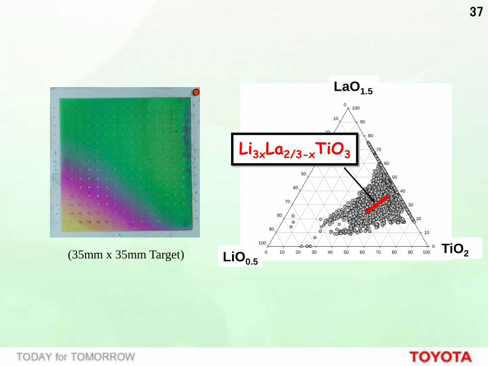
37
TiO2
0 10 20 30 40 50 60 70 80 90 100
LaO1.5
0
10
20
30
40
50
60
70
80
90
100
LiO0.5
0
10
20
30
40
50
60
70
80
90
100
(35mm x 35mm Target) LiO0.5
LaO1.5
TiO2
Li3xLa2/3-xTiO3
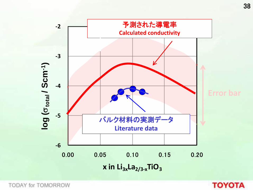
38
-6
-5
-4
-3
-2
0.00 0.05 0.10 0.15 0.20
log
(s
tota
l/
Sc
m-1
)
x in Li3xLa2/3-xTiO3
Error bar
バルク材料の実測データ Literature data
予測された導電率 Calculated conductivity

39
La1 La2
La1 La2
90°ドメイン
Anti-phase domain (APB)

40

41
10 100 1000 10000
’10
’20
’15
NiMH battery
1000
2000
4000
6000
8000
10000
Limit of conventional
batteries
All Solid
Battery
Metal Air
Battery
Sakic
hi
Batt
ery
Po
we
r D
en
sit
y (W/ℓ
)
Volumetric Energy Density (Wh/ℓ)Mile Range

42
固体の生成物が析出
O2
LiOH水溶液 負極集電体 正極集電体
カーボン 触媒 固体電解質 負極 酸素透過膜
Li+
Li ⇔
Li+ + e-
4Li+ + 4e- + O2 + 2H2O 4LiOH
放電
充電
正極反応
O2
Li+
セパレーター 負極集電体 正極集電体
カーボン 触媒 電解液 負極 酸素透過膜
Li ⇔
Li+ + e-
正極反応
2Li+ + 2e- + O2 Li2O2
放電
充電
水溶液系 Li空気電池 非水系 Li空気電池
生成物は電解液に溶解
生成物
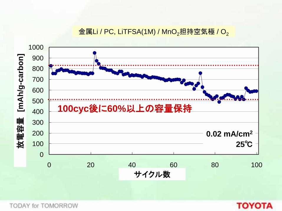
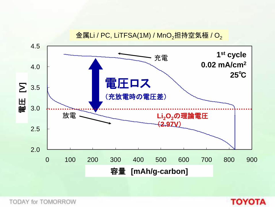
金属Li / PC, LiTFSA(1M) / MnO2担持空気極 / O2
0
100
200
300
400
500
600
700
800
900
1000
0 20 40 60 80 100
Cycle number
Dis
ch
arg
e c
ap
acity [
mA
h/g
-ca
rbo
n]
放電
容量
[m
Ah
/g-c
arb
on
]
サイクル数
0.02 mA/cm2
25℃
100cyc後に60%以上の容量保持
2.0
2.5
3.0
3.5
4.0
4.5
0 100 200 300 400 500 600 700 800 900
Capacity [mAh/g-carbon]
Voltage [
V]
容量 [mAh/g-carbon]
電圧
[V
]
放電
充電
電圧ロス (充放電時の電圧差)
金属Li / PC, LiTFSA(1M) / MnO2担持空気極 / O2
Li2O2の理論電圧(2.97V)
1st cycle
0.02 mA/cm2
25℃

45
Li+
O
=
O- XO C
e-
CO2
XO・
< 放電 >
< 充電 >
O
=
C OLi XO
Li+
PC
(副反応)
使用した電池材料
解析により同定した
生成物
有機溶媒
Li+
O2
2e-
PP13TFSA
(正反応)
2Li+
(X = alkyl group or Li)
O O
O O
O
O
O2
Li2O2

46
0
500
1000
1500
2000
2500
3000
40 50 60 70 80 90
Energy [eV]
Inte
nsity
PP13TFSA : 5.9mAh程度
100nm程度
の粒子
MnO2/CB
-4
-2
0
2
4
6
40 50 60 70 80 90
Energy [eV]
Secondary
diff
ere
ntia
l inte
nsity
Li2CO3
Li2O2
sample
Li2CO3 Li2O2
sample

中略

48
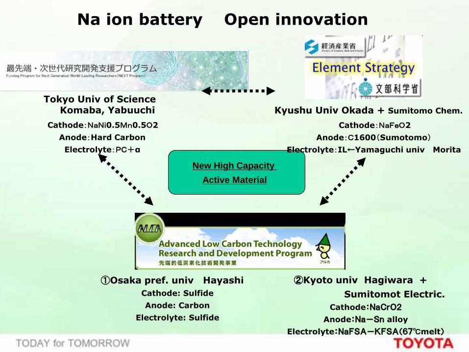
Tokyo Univ of Science Komaba, Yabuuchi
Cathode:NaNi0.5Mn0.5O2
Anode:Hard Carbon
Electrolyte:PC+α
①Osaka pref. univ Hayashi
Cathode: Sulfide
Anode: Carbon
Electrolyte: Sulfide
Kyushu Univ Okada + Sumitomo Chem.
Cathode:NaFeO2
Anode:C1600(Sumotomo)
Electrolyte:IL←Yamaguchi univ Morita
②Kyoto univ Hagiwara +
Sumitomot Electric.
Cathode:NaCrO2
Anode:Na-Sn alloy
Electrolyte:NaFSA-KFSA(67℃melt)
New High Capacity
Active Material
Na ion battery Open innovation

Fig. Li-M-P (M = Ni, Co and Mn) system Fig. Na-M-P (M = Ni, Co and Mn) system
1) Na-M-P 2) Li-M-P
Marisite-NaMPO4
Olivine-LiMPO4
×
1Dイオンチャンネル
イオンチャンネルなし
○

Refs. 1) F. Sanz et al., Chem Mater. 13 1334-1340 (2001). 2) F. Sanz et al., J. solid state chem. 123 129 (1996).
Na4M3(PO4)2P2O7
[M=Ni, Co, Mn]
(I) a軸方向 (II) b軸方向
b
c
a
c
Na1
Na2 Na3
Na4
(III) c軸方向
a
b
Na3Na4
Fig. Na-M-P (M = Ni, Co and Mn) system
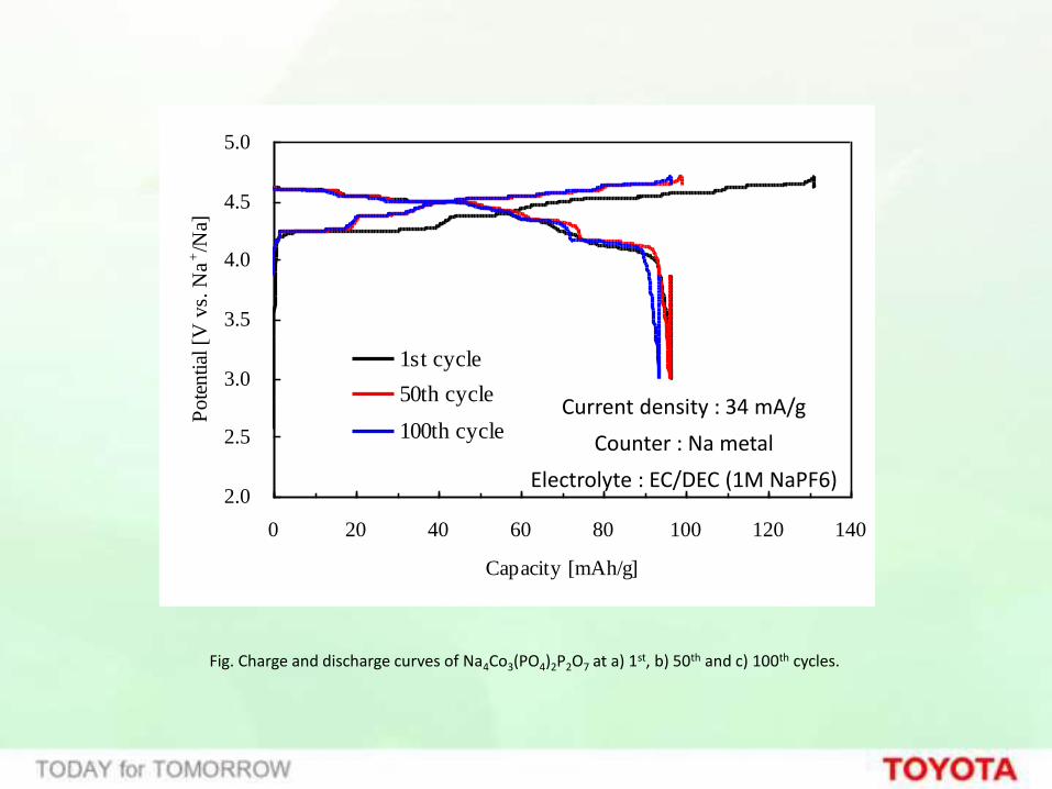
2.0
2.5
3.0
3.5
4.0
4.5
5.0
0 20 40 60 80 100 120 140
Capacity [mAh/g]
Pote
ntial
[V
vs.
Na
+/N
a]
1st cycle
50th cycle
100th cycle
Fig. Charge and discharge curves of Na4Co3(PO4)2P2O7 at a) 1st, b) 50th and c) 100th cycles.
Current density : 34 mA/g
Counter : Na metal
Electrolyte : EC/DEC (1M NaPF6)

New Principal, New process Fundamental technology
Material
Product
Device
Society
Green
innovation
Fun to Drive
HV
plug-in HV
EV
Innovative Battery
1)All Solid Battery
2)Metal Air Battery
Nano Material
1)Solid Electrolyte
2)Carbon alloy Catalyst
3)New active material
Nano particle Nano coating
self organization
Interface phenomina analysis

54

55

56
「Nano structure control」
Latest development Issues
Nano to bulk scale up
such as)
Interface structure
layer structure
self organize
in-situ analysis
Step1
・nano particle fabrication
Step2
・nano composite magnet
・nano cluster catalyst

58

New Principal, New process Fundamental technology
Material
Product
Device
Society
Green
innovation
Fun to Drive
HV
plug-in HV
EV
Innovative Battery
1)All Solid Battery
2)Metal Air Battery
Nano Material
1)Solid Electrolyte
2)Carbon alloy Catalyst
3)New active material
Nano particle Nano coating
self organization
Interface phenomina analysis

60
http://www.toyota.co.jp/jpn/events/culture/dreamcar/gallery.html