The Ray Vector A light ray can be defined by two co-ordinates: x in, in x out, out its position, x...
24
The Ray Vector A light ray can be defined by two co-ordinates: x in , in x out , out its position, x its slope, Optical axis optical ray x These parameters define a ray vector, which will change with distance and as the ray propagates through x
-
date post
22-Dec-2015 -
Category
Documents
-
view
214 -
download
0
Transcript of The Ray Vector A light ray can be defined by two co-ordinates: x in, in x out, out its position, x...
The Ray Vector
A light ray can be defined by two co-ordinates:
xin, in
xout, out
its position, x
its slope,
Optical axis
optical ray
x
These parameters define a ray vector,
which will change with distance and as
the ray propagates through optics.
x

For many optical components, we can define 2 x 2 ray matrices.
An element’s effect on a ray is found by multiplying its ray vector.
Ray matricescan describesimple and com-plex systems.
These matrices are often called ABCD Matrices.
in
in
x
A B
C D
Optical system ↔ 2 x 2 Ray matrix
out
out
x
Ray Matrices

Ray matrices as derivatives
We can write these equations in matrix form.
out in
out inD
B x
C
x A
out
in
out
in
x
x
out
inx
out
in
x
angular magnification
spatial magnification
out ioutout
i ni
n in nx x
xx
x
out in ioutut
nin i
onx
x
Since the displacements and angles are assumed to be small, we can
think in terms of partial derivatives.

Ray matrix for free space or a medium
If xin and in are the position and slope upon entering, let xout and out be the position and slope after propagating from z = 0 to z.
out in in
out in
x x z
xin, in
z = 0
xout out
z 1
0 1out in
out in
x xz
Rewriting these expressions in matrix notation:
1=
0 1space
zO
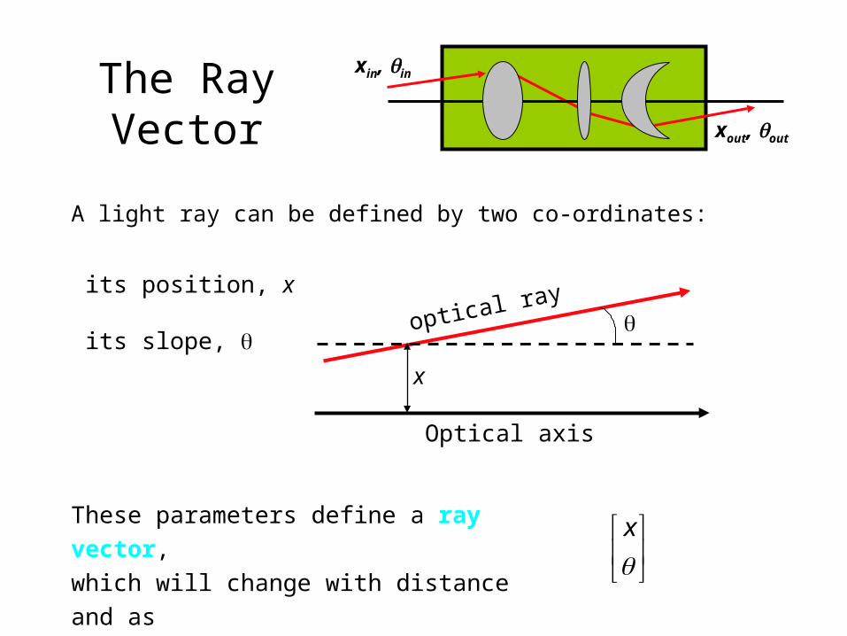
Ray matrix for a lens
The quantity, f, is the focal length of the lens. It’s the single most important parameter of a lens. It can be positive or negative.
In a homework problem, you’ll extend the Lens Maker’s Formula to lenses of greater thickness.
1 0=
-1/ 1lensOf
If f > 0, the lens deflects rays toward the axis.
f > 0
If f < 0, the lens deflects rays away from the axis.
f < 0
1 21/ ( 1)(1/ 1/ )f n R R
R1 > 0R2 < 0
R1 < 0R2 > 0

A lens focuses parallel rays to a point one focal length away.
01 1 0 0
/0 1 1/ 1 0 1/ 1 0out in in
out in
x f x f x
x ff f
f
f
At the focal plane, all rays converge to the z axis (xout = 0) independent of input position.
Parallel rays at a different angle focus at a different xout.
A lens followed by propagation by one focal length:
Assume all input rays have in = 0
For all rays xout = 0!
Looking from right to left, rays diverging from a point are made parallel.

Consecutive lenses
2 1 1 2
1 0 1 0 1 0= =
-1/ 1 -1/ 1 -1/ 1/ 1totOf f f f
f1 f2
Suppose we have two lenses right next to each other (with no space in between).
tot 1 21/ = 1/ +1/f f f
So two consecutive lenses act as one whose focal length is computed by the resistive sum.
As a result, we define a measure of inverse lens focal length, the diopter. 1 diopter = 1 m-1

A system images an object when B = 0.
When B = 0, all rays from a point xin arrive at a point xout, independent of angle.
xout = A xin When B = 0, A is the magnification.
0out in in
out in in in
x x A xA
C x DC D
/
1/ 1/ 1/
0
o i o i
o i o i
B d d d d f
d d d d f
if
1 1 0 1
0 1 1/ 1 0 1
11
1/ 1 /0 1
1 / /
1/ 1 /
i o
oi
o
i o i o i
o
d dO
f
dd
f d f
d f d d d d f
f d f
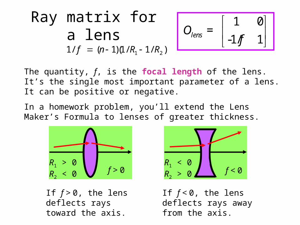
The Lens LawFrom the object to the image, we have:
1) A distance do
2) A lens of focal length f3) A distance di
1 1 1
o id d f
This is the Lens Law.

Imaging Magnification
1 1 1
o id d f
1 11 / 1i i
o i
A d f dd d
i
o
dM
d
If the imaging condition,
is satisfied, then:
1 / 0
1/ 1 /i
o
d fO
f d f
1 11 / 1o o
o i
D d f dd d
1/o
i
dM
d
0
1/ 1/
MO
f M
So:

magnification
• Linear or transverse magnification — For real images, such as images projected on a screen, size means a linear dimension
• Angular magnification — For optical instruments with an eyepiece, the linear dimension of the image seen in the eyepiece (virtual image in infinite distance) cannot be given, thus size means the angle subtended by the object at the focal point (angular size). Strictly speaking, one should take the tangent of that angle (in practice, this makes a difference only if the angle is larger than a few degrees). Thus, angular magnification is defined as

f
It depends on how much of the lens is used, that is, the aperture.
Only one plane is imaged (i.e., is in focus) at a time. But we’d like objects near this plane to at least be almost in focus. The range of distances in acceptable focus is called the depth of field.
Out-of-focus plane
Focal plane
Object
Image
Size of blur in out-of-focus
plane
Aperture
The smaller the aperture, the more the depth of field.
Depth of Field

Gaussian Beams

The F-number, “f / #”, of a lens is the ratio of its focal length and its diameter.
f / # = f / d
f
f
d1 f
f
d2
f / # = 1 f / # = 2
Large f-number lenses collect more light but are harder to engineer.
F-number
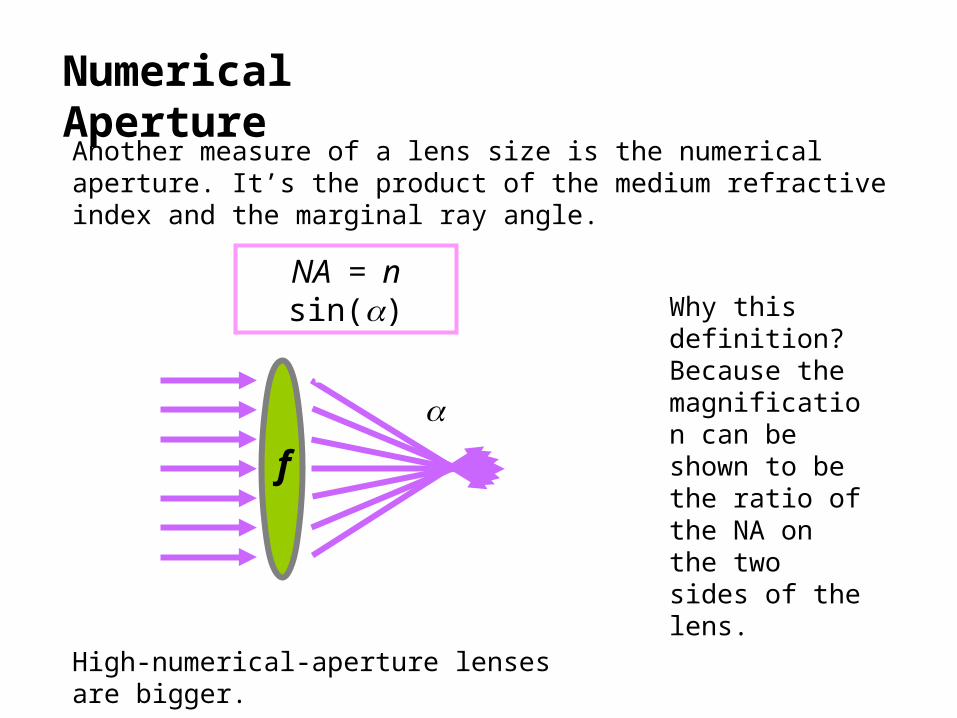
Another measure of a lens size is the numerical aperture. It’s the product of the medium refractive index and the marginal ray angle.
NA = n sin()
High-numerical-aperture lenses are bigger.
f
Numerical Aperture
Why this definition? Because the magnification can be shown to be the ratio of the NA on the two sides of the lens.
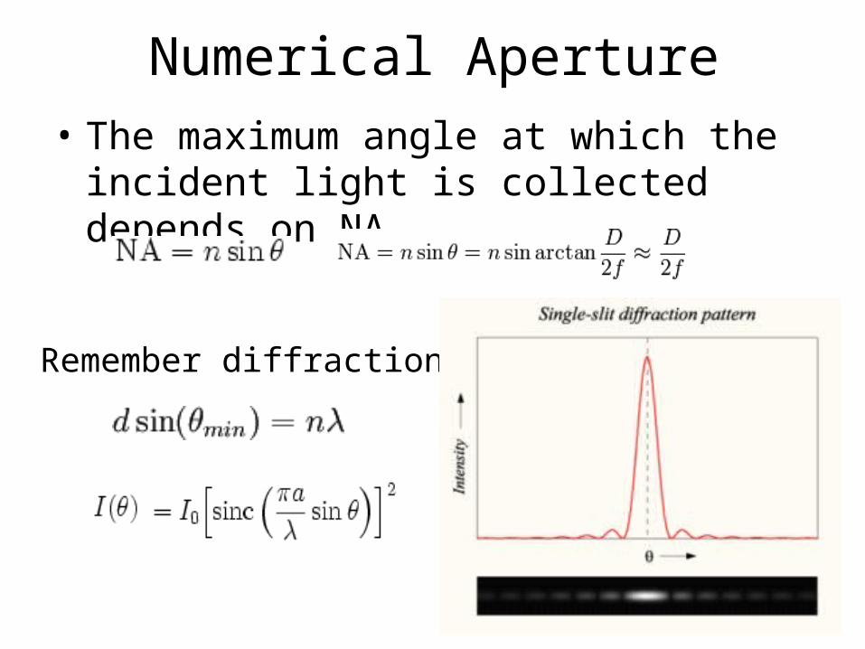
Numerical Aperture• The maximum angle at which the incident
light is collected depends on NA
Remember diffraction

Numerical Aperture• The maximum angle at which the incident
light is collected depends on NA
Remember diffraction
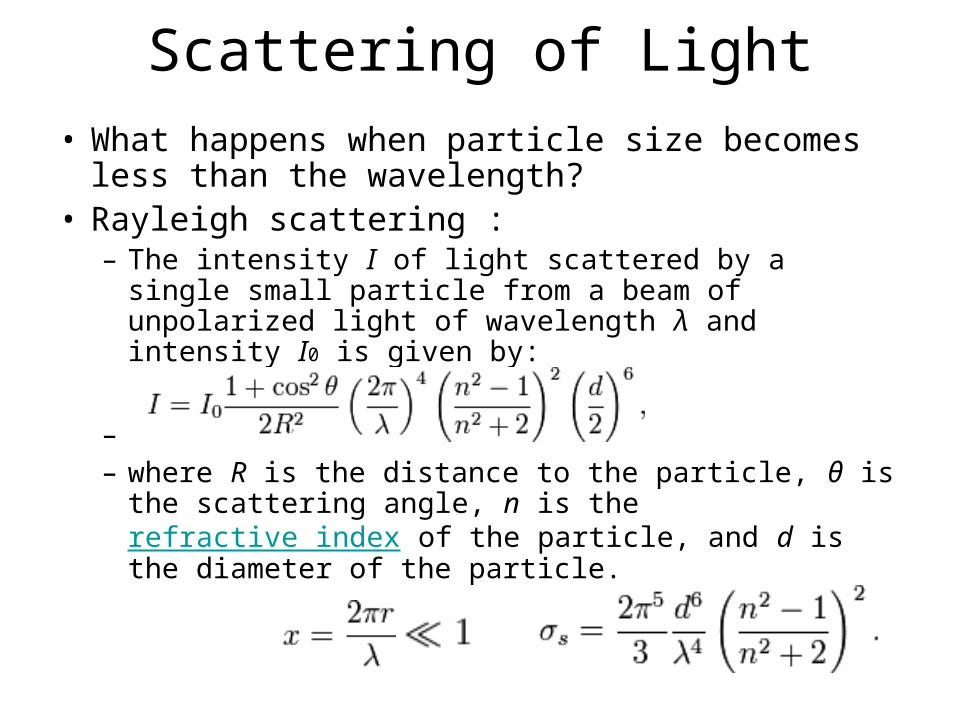
Scattering of Light
• What happens when particle size becomes less than the wavelength?
• Rayleigh scattering :– The intensity I of light scattered by a single small
particle from a beam of unpolarized light of wavelength λ and intensity I0 is given by:
– – where R is the distance to the particle, θ is the
scattering angle, n is the refractive index of the particle, and d is the diameter of the particle.

Scattering of Light• What happens when particle size
becomes less than the wavelength?
• MIE scattering :– Use a series sum to calculate scattered
intensity at arbitrary particle diameter
http://omlc.ogi.edu/calc/mie_calc.html
Sphere Diameter 0.10 microns
Refractive Index of Medium 1.0
Real Refractive Index of Sphere 1.5
Imaginary Refractive Index of Sphere 0
Wavelength in Vacuum 0.6328 microns
Concentration 0.1 spheres/micron3
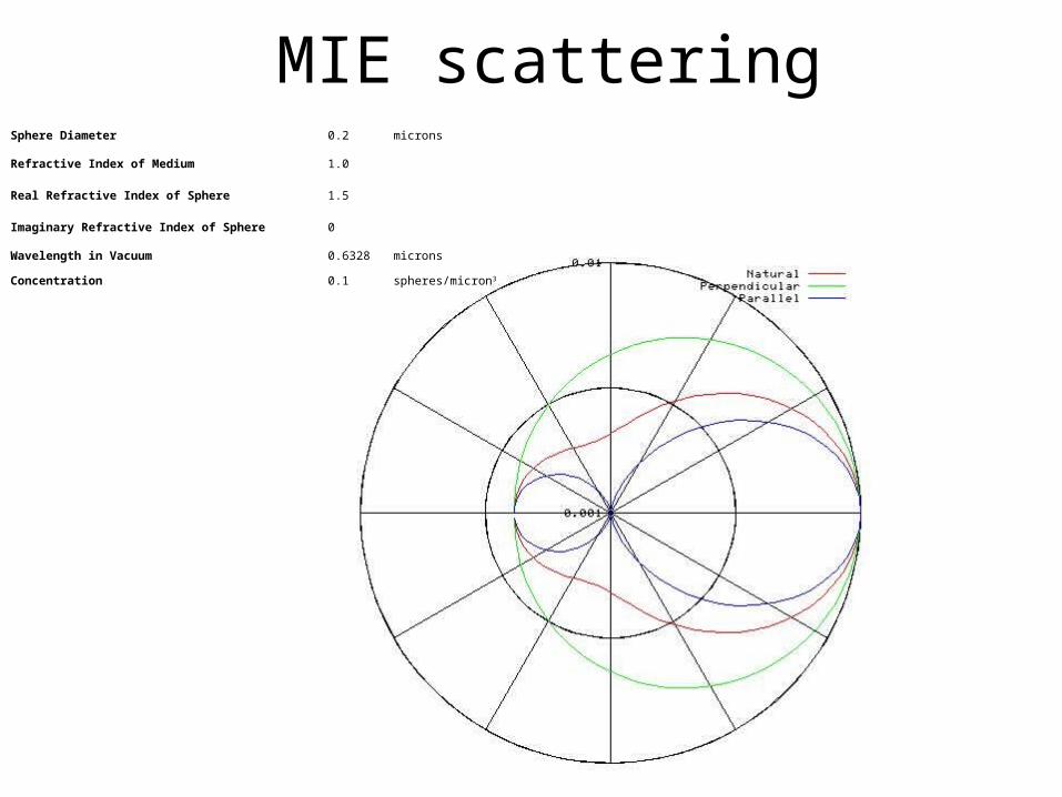
MIE scatteringSphere Diameter 0.2 microns
Refractive Index of Medium 1.0
Real Refractive Index of Sphere 1.5
Imaginary Refractive Index of Sphere 0
Wavelength in Vacuum 0.6328 microns
Concentration 0.1 spheres/micron3

Telescopes
A telescope should image an object, but, because the object will have a very small solid angle, it should also increase its solid angle significantly, so it looks bigger. So we’d like D to be large. And use two lenses to square the effect.
0
1/ 1/imaging
MO
f M
2 1
2 2 1 1
0 0
1/ 1/ 1/ 1/telescope
M MO
f M f M
1 2
1 2 2 1 1 2
0
/ / 1/
M M
M f M f M M
where M = - di / do
So use di << do for both lenses.
Note that this is easy for the first lens, as the object is really far away!
M1 M2
Image plane #1
Image plane #2
Keplerian telescope

Telescope Terminology

Micro-scopes M1 M2
Image plane #1
Image plane #2
Microscopes work on the same principle as telescopes, except that the object is really close and we wish to magnify it.
When two lenses are used, it’s called a compound microscope.
Standard distances are s = 250 mm for the eyepiece and s = 160 mm for the objective, where s is the image distance beyond one focal length. In terms of s, the magnification of each lens is given by:
|M| = di / do = (f + s) [1/f – 1/(f+s)] = (f + s) / f – 1 = s / f
Eye- piece
Many creative designs exist for microscope objectives. Example: the Burch reflecting microscope objective:
Objective
Object To eyepiece

Example: Magnifying Glass