THE PROJECT FOR DEVELOPMENT OF WATER …open_jicareport.jica.go.jp/pdf/12113759_01.pdfTHE ISLAMIC...
117
THE ISLAMIC REPUBLIC OF AFGHANISTAN DEHSABZ-BARIKAB CITY DEVELOPMENT AUTHORITY (DCDA) THE PROJECT FOR DEVELOPMENT OF WATER SUPPLY FACILITIES IN DEHSABZ SOUTH AREA OUTLINE DESIGN REPORT FEBRUARY 2013 JAPAN INTERNATIONAL COOPERATION AGENCY (JICA) CTI ENGINEERING INTERNATIONAL CO., LTD. YACHIYO ENGINEERING CO., LTD. GE JR 13-072
Transcript of THE PROJECT FOR DEVELOPMENT OF WATER …open_jicareport.jica.go.jp/pdf/12113759_01.pdfTHE ISLAMIC...

THE ISLAMIC REPUBLIC OF AFGHANISTANDEHSABZ-BARIKAB CITY DEVELOPMENT AUTHORITY(DCDA)
THE PROJECT FOR DEVELOPMENT OF WATER SUPPLY FACILITIES
IN DEHSABZ SOUTH AREA
OUTLINE DESIGN REPORT
FEBRUARY 2013
JAPAN INTERNATIONAL COOPERATION AGENCY (JICA)
CTI ENGINEERING INTERNATIONAL CO., LTD. YACHIYO ENGINEERING CO., LTD.
GE
JR
13-072

i
SUMMARY
1. Outline of the Country The population of the Islamic Republic of Afghanistan (hereinafter referred to as "Afghanistan"), is
approximately 25 million (2011, the World Bank), and the main industries are agriculture (wheat, barley, potatoes, rice, almonds, sugarcane, etc.). Construction and service industries have been being developed by the reconstruction demands in Kabul and other major urban centers. However, it remains one of the poorest countries in the world. It is placed at the 172nd out of 187 countries by the UNDP human development index of 2011.
The GDP stands at US$17.2 billion (2010, the World Bank) and in terms of industry-separate breakdown, primary industry accounts for 29.9 percent, secondary industry for 22.2 percent and tertiary industry for 47.9 percent (2011, the World Bank). The economic growth rate is 22.5 percent (2010, the World Bank).
The social and economic infrastructures of Afghanistan suffered from massive damages as a result of the civil war that raged for more than 20 years. However, following the collapse of Taliban Regime, the infrastructures have been being rebuilt through the supports of international organizations. The national governance mechanism building process has been finished so far. Improvements have been appearing such as 5.7 million of repatriated refugees and increase of school children (from less than 1 million in 2001 to 8 million by 2011).
In order to ensure further reconstruction and development, many fields of social infrastructure remain missing and there are urgent needs to expand assistances not only to the metropolitan area but also to the provinces.
2. Background, History and Outline of the Project
The population of Kabul City, the capital of Afghanistan was about 2 million in 1999.It is estimated at 4 or 5 million as of 2012. Moreover, it is forecasted to reach 6.5 million in 2025. Under such circumstances, the Government of Afghanistan established Dehsabz-Barikab City Development Authority (hereinafter referred as to “DCDA”) and decided to develop a new city for the increasing population, which was located in the north east area of Kabul City for approximately 740 km2 (74,000ha). The Master Plan for the Kabul Metropolitan Area Development in the Islamic Republic of Afghanistan (hereinafter referred to as “MP”) was formulated in 2009 and public infrastructure plans for development of initial development area (Dehsabz South area) was prepared in 2011. To facilitate smooth development of the new city, the Government of Japan assists DCDA through the Project for Promotion of Kabul Metropolitan Area Development.
While DCDA promotes the development of infrastructures, it has prepared private sector utilization plans, including financial analysis and guidelines for private sectors.
In parallel to these activities, DCDA selected an area of approximately 830 ha for initial development, which is called as “Parcel-1” for the population of 42,000 as a development model. DCDA has currently commenced design of public infrastructures such as roads and water supply facilities and advertisement for private developers. DCDA, the planner and executing agency of the new city, requested the cooperation for construction of roads, water distribution lines, water transmission to Parcel-1 and water resources development to the Government of Japan. The

ii
Government of Japan has assisted designs and preparation of tender documents through the Sub-Project for the Infrastructure Development for Parcel-1 Area in Dehsabz South (hereinafter referred to as Infrastructure SP) since March 2011.
The Government of Japan decided to support construction of a part of roads and water distribution mains in Parcel-1 and has prepared a pilot project within Infrastructure SP.
This pilot project does not include construction works for the remaining water distribution lines and water resources. Therefore, DCDA requested the grant aid to the Government of Japan in October 2012.
3. Outline of the Study Findings and Contents of the Project
JICA dispatched the preparatory survey team several times from November 2012 to February 2013 in order to conduct fieldwork on the outline design study for target area. The team held discussions with officials of the Government of Afghanistan and conducted survey in the target area. Based on the results of the field surveys, the team conducted the outline design on the optimum project contents and compiled the findings into the outline design report.
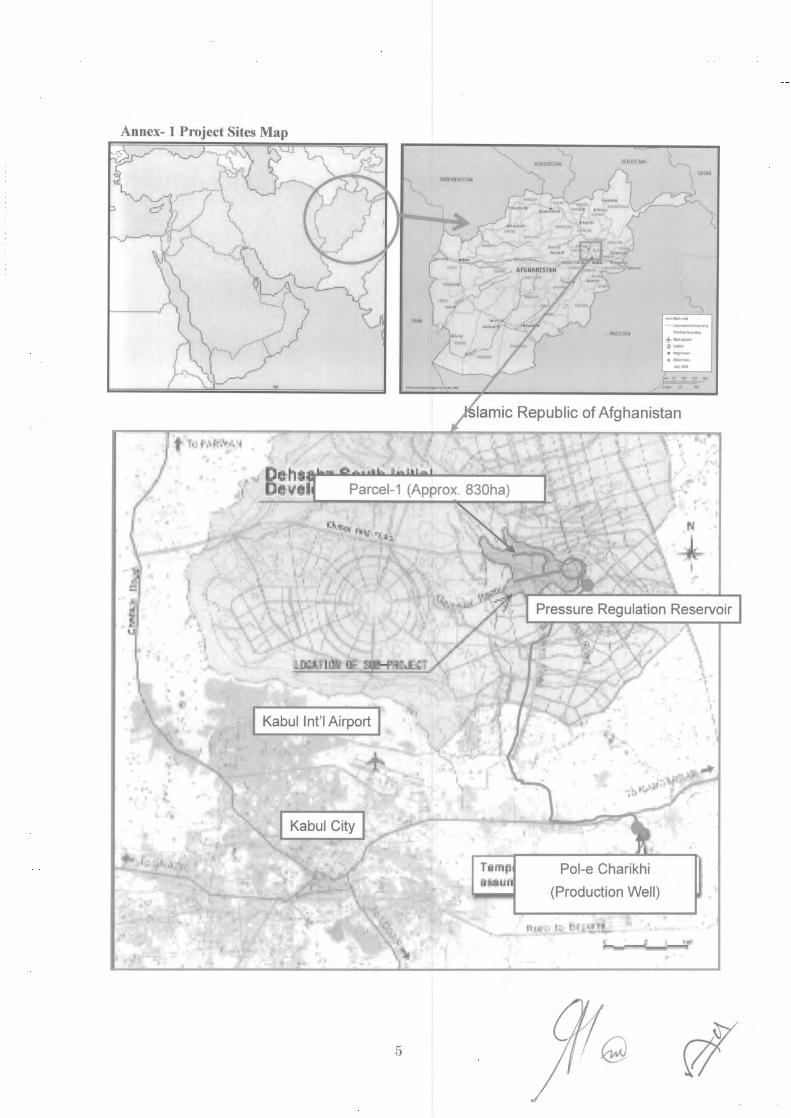
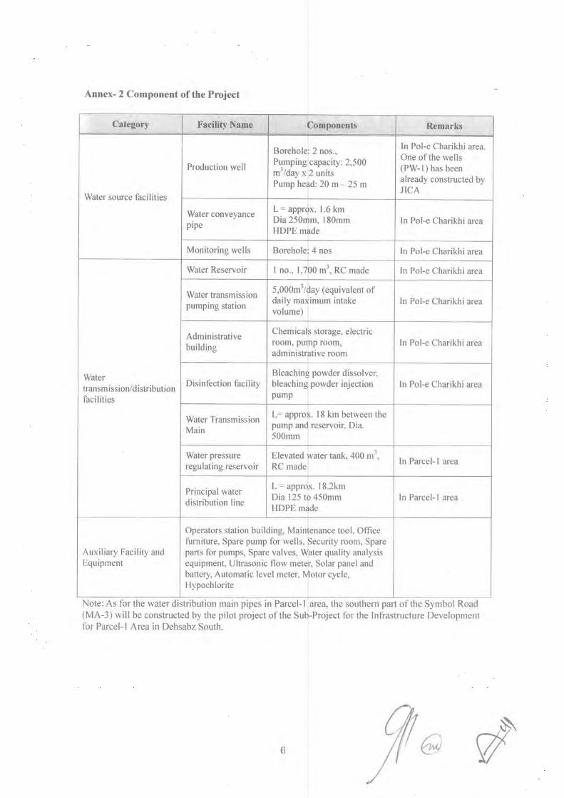
The Government of Afghanistan plans to develop the Parcel-1 area by 2015. However, there are neither the existing water supply facilities nor sufficient water resources which sustain the Parcel-1 area. Therefore, it is necessary to transmit the water from water resource outside of Parcel-1. Under such circumstances, the project objectives are to develop water resource, to construct intake and water transmission facilities and principal water distribution lines, and to secure the required water in the Parcel-1. This Project covers production wells, a reservoir, a water transmission pump facility, a water transmission main, a water pressure regulating reservoir and principal water distribution lines as shown in Figure-1 and Table-1.

iii
Figure-1 Outline of Japanese Assistance
Table-1 Scope of Japanese Assistance Facility Name Components Specifications
1. Pol-e Charihi Well Station (1) Production well (PW-1, PW-2)
Deep well, Submersible pump, Power receiving equipment
Production well: 2 units (One (1) well is the existing test well) Pump Capacity; 2,500 m3/day x 2 units Pumping Head: 23 m. Necessary electrical facilities.
(2) Water Conveyance Pipeline
Water conveyance facility L = 1.6 km, Outer Diameter: 250 mm and 180 mm, HDPE
(3) Reservoir and Water Transmission Pimp Facility
Reservoir (R-Well) 1 location, 1,700 m3 (850 m3 x 2 units), Reinforced concrete
Water transmission pump, Power receiving equipment
Pump capacity: 1.7 m3/min x 3 units and 1 unit for standby, Pump head: 90m, necessary electrical facilities.
Disinfection facility Calcium Hypochlorite Solution Tank, Calcium Hypochlorite Dosing Pump, necessary electrical facilities.
(4) Monitoring Wells Deep well Monitoring wells: 4 units (5) Maintenance facilities Operation room at Pol-e
Charihi Well Station Guardhouse, Flow meter, water quality analytical equipment, Tools for maintenance
2. Pipeline Transmission and distribution lines
L = 36.5 km, Outer diameter: 125 ~ 500 mm, HDPE
3. Water pressure regulating reservoir
Elevated tank (R-P1) 1 location, 400 m3 (400 m3 x 1 unit), Reinforced concrete
4. Project Implementation Schedule and Rough Project Cost In the case where the Project is implemented under the Japan’s grant aid scheme, it is scheduled to
take 6.5 months for the tender process including preparation of tender documents and 14.5 months for construction works after handing the design to the procurement agent (UNOPS).
Water pressure regulating reservoir (R-P1)
Water Transmission main L=18.1km
Water Reservoir & transmission pump f ilitProduction Well No.1 (PW-1)
Production Well No.2 (PW-2) Water conveyance pipelines
Principal Water Distribution Lines
Parcel-1

iv
4.1 Cost to be Borne by Japanese Side This information is closed due to the confidentiality.
4.2 Cost to be Borne by Afghanistan Side Total estimated Cost: 420 million Japanese Yen
(Unit: Thousand AFA) Contents Quantity Cost (Local Currency) Remarks
Bank Commission for opening bank account
1 1,699 (Approx. 3 million yen)
DCDA
Other distribution mains which are excluded from the grant aid project
Approx. 17.2km
84,045 (Approx. 127 million yen)
DCDA
Other distribution branch lines which are excluded from the grant aid project
Approx. 160km
estimated
192,253 (Approx. 290 million yen)
Private Developers
Total 277,997 (Approx. 420 million yen)
4.3 Conditions for Cost Estimation
The conditions for cost estimation are shown below; 1. Date : November, 2012 2. Exchange Rate : US$ = 79.99 YEN
1AFA = 1.507 YEN 3. Construction Period : 21 months 4. Tax : As of Japanese Grant Aid scheme
5. Project Evaluation
This Project is relevant to the needs of Afghanistan and development policy as well as Japan’s assistance policy. This Project will contribute to secure required water for the Parcel 1 and will be a model case for development of the new city. Therefore, the relevance is evaluated as high.
5.1 Quantitative Project Evaluation
Figure-2 Quantitative Project Evaluation Indicator Current Condition(2012) Index(2018)
[3 years after commission] Water supply (m3/day) 0 5,000 Service Population 0 42,000 Water Supply Hours (Hour / Day) 0 24
5.2 Qualitative Project Evaluation Construction of water supply and transmission facility will promote the development of Parcel-1
area.

THE PROJECT FOR DEVELOPMENT
OF WATER SUPPLY FACILITIES IN DEHSABZ SOUTH AREA OUTLINE DESIGN REPORT
Contents
Summary Contents Location Map/ Perspective List of Figures & Tables Abbreviations Table of Contents
Page Background of the Project .................................................................................................... 1-1 Chapter 1
1.1. Background of the Requested Project ............................................................................................... 1-1 1.2. Contents of the Requested Project..................................................................................................... 1-1 1.3. Environmental and Social Consideration .......................................................................................... 1-2
Outline of the Project Components ............................................................................................. 1-2 1.3.1 Environmental and Social Conditions ......................................................................................... 1-2 1.3.2 Legal Framework for Environmental and Social Consideration in Afghanistan ......................... 1-2 1.3.3 Alternative Analysis .................................................................................................................... 1-3 1.3.4 Screening Report and Project Categorization .............................................................................. 1-4 1.3.5 Scoping ........................................................................................................................................ 1-5 1.3.6 TOR for Environmental and Social Surveys ............................................................................... 1-7 1.3.7 Result of the Study on Environmental and Social Consideration................................................ 1-7 1.3.8 Evaluation of the Impact ............................................................................................................. 1-9 1.3.9
Mitigation Measures and Cost ................................................................................................. 1-10 1.3.10 Environmental Management and Monitoring Plans ................................................................ 1-14 1.3.11 Stakeholders Meeting .............................................................................................................. 1-15 1.3.12
1.4. Land Acquisition and Resettlement ................................................................................................. 1-15 Necessity of Land Acquisition and Resettlement ...................................................................... 1-15 1.4.1 Legal Framework on Land Acquisition and Resettlement ........................................................ 1-18 1.4.2 Stakeholders’ Meeting ............................................................................................................... 1-18 1.4.3
1.5. Others .............................................................................................................................................. 1-18 Monitoring Form ....................................................................................................................... 1-18 1.5.1 Environmental Check List ......................................................................................................... 1-23 1.5.2 Concepts of the Project ............................................................................................................ 2-1 Chapter 2
2.1. Basic Concept of the Project ............................................................................................................. 2-1 Overall Goal and Project Purpose ............................................................................................... 2-1 2.1.1
Basic Concept of the Project ....................................................................................................... 2-1 2.1.22.2. Outline Design of the Japanese Assistance ....................................................................................... 2-1
Design Policy .............................................................................................................................. 2-1 2.2.1 Basic Plan (Construction Plan / Equipment Plan) ....................................................................... 2-3 2.2.2 Facility Layout Plan .................................................................................................................... 2-7 2.2.3 Auxiliary Facility and Equipment ............................................................................................. 2-23 2.2.4 Priority in Project Components ................................................................................................. 2-23 2.2.5 Outline Design Drawing ............................................................................................................ 2-25 2.2.6 Implementation Plan ................................................................................................................. 2-34 2.2.7
2.3. Obligations of Recipient Country.................................................................................................... 2-41 General Items ............................................................................................................................ 2-41 2.3.1 Special Items ............................................................................................................................. 2-41 2.3.2
2.4. Project Operation Plan .................................................................................................................... 2-41 Responsible Setup in Afghanistan ............................................................................................. 2-41 2.4.1 Basic Policy ............................................................................................................................... 2-42 2.4.2 Items for Regular Check ........................................................................................................... 2-43 2.4.3 Spare Parts Purchase Plan ......................................................................................................... 2-45 2.4.4
2.5. Project Cost ..................................................................................................................................... 2-46 Cost to be Borne by Japanese Side ............................................................................................ 2-46 2.5.1 Cost to be Borne by Afghanistan Side ....................................................................................... 2-46 2.5.2 Conditions for Cost Estimation ................................................................................................. 2-46 2.5.3 Operation and Maintenance Cost .............................................................................................. 2-46 2.5.4 Project Evaluation ................................................................................................................ 3-1 Chapter 3
3.1. Preconditions ..................................................................................................................................... 3-1 3.2. Necessary Inputs by Recipient Country ............................................................................................ 3-1 3.3. Important Assumptions ..................................................................................................................... 3-1 3.4. Project Evaluation ............................................................................................................................. 3-1
Relevance .................................................................................................................................... 3-1 3.4.1 Effectiveness ............................................................................................................................... 3-1 3.4.2

Location Map
Islam Republic of Afghanistan
Water Transmission Main
Water Pressure Regulating Reservoir(R-P1)
Pol-e Charihi Well Station
Percel-1 Principal Water Distribution Lines

Perspective of This Project

List of Figures Figure 1-1 Procedure for Environmental Permit ............................................................................... 1-3
Figure 1-2 Present Situation of the Route for Principal Water Transmission Main .......................... 1-8
Figure 1-3 Flora in the Area of Water Pressure Regulating Reservoir .............................................. 1-9
Figure 2-1 Outline of the Project ....................................................................................................... 2-4
Figure 2-2 Layout of Pol-e Charikhi Well Station............................................................................. 2-8
Figure 2-3 Pol-e Charikhi Well Station System ................................................................................ 2-8
Figure 2-4 Standard Cross Section of Water Conveyance Line ........................................................ 2-9
Figure 2-5 Calculation of Friction Loss of Well Pumps and Water Conveyance Lines .................. 2-10
Figure 2-6 Longitudinal Profile of Transmission Pumps and Water Transmission Main ................ 2-12
Figure 2-7 Negative Pressure on Water Transmission Main ........................................................... 2-13
Figure 2-8 10 kV Power Supply Route ........................................................................................... 2-15
Figure 2-9 Operation Concept on Well Pump Control .................................................................... 2-16
Figure 2-10 Operation Concept on Water Transmission Pump Control .......................................... 2-17
Figure 2-11 Cross Section of the Water Pressure Regulating Reservoir ......................................... 2-19
Figure 2-12 Plan of Water Distribution Lines ................................................................................. 2-21
Figure 2-13 Plan of Principal Water Distribution Lines .................................................................. 2-22
Figure 2-14 Implementation Scheme .............................................................................................. 2-34
Figure 2-15 Maintenance Flow of Water Supply Facilities ............................................................. 2-43
List of Tables
Table 1.1 Components of the requirement for the Japan’s Grant Aid ............................................... 1-1
Table 1.2 Basic Environmental and Social Condition ....................................................................... 1-2
Table 1.3 Screening Checklist ........................................................................................................... 1-4
Table 1.4 Scoping Matrix .................................................................................................................. 1-6
Table 1.5 TOR for environmental and social surveys ....................................................................... 1-7
Table 1.6 Result of the study on Environmental and social Consideration ....................................... 1-7
Table 1.7 Result of Impact Assessment ........................................................................................... 1-10
Table 1.8 Potential Impacts and Mitigation Measures .................................................................... 1-11
Table 1.9 Impact and Mitigation Measure (Construction Phase) .................................................... 1-13
Table 1.10 Impact and Mitigation Measure (Operation) ................................................................. 1-14
Table 1.11 Environmental Monitoring Plan(Construction phase) .............................................. 1-14
Table 1.12 Environmental Monitoring Plan(Operation phase) .................................................. 1-15
Table 1.13 Summary of First Stakeholders’ Meeting ...................................................................... 1-15
Table 1.14 Status of Land Acquisition and Necessary Permits ....................................................... 1-17
Table 1.15 MONITORING FORM (Construction Phase) ............................................................... 1-19
Table 1.16 MONITORING FORM (Operation Phase) ................................................................... 1-21
Table 2.1 Scope of Japanese Assistance ............................................................................................ 2-4
Table 2.2 Result of Water Quality Analysis....................................................................................... 2-5
Table 2.3 Result of Heavy Metal Analysis ........................................................................................ 2-6
Table 2.4 Design Condition ............................................................................................................... 2-6
Table 2.5 Outline of Production Wells .............................................................................................. 2-9
Table 2.6 Main feature of the conveyance pipeline ........................................................................... 2-9
Table 2.7 Calculation of Friction Loss ............................................................................................ 2-10
Table 2.8 Result of Simulation for Pumping Head and Pipe Diameter: Transmission Pump ......... 2-12
Table 2.9 Outline of Monitoring Wells ............................................................................................ 2-14
Table 2.10 Necessary Electric Power for Pump .............................................................................. 2-14
Table 2.11 Power Receiving Equipment ......................................................................................... 2-15
Table 2.12 Main Control Panels in Pump House............................................................................. 2-16
Table 2.13 Water Transmission Main .............................................................................................. 2-18
Table 2.14 Pipeline Route and Location .......................................................................................... 2-18
Table 2.15 Outline of the Water Pressure Regulating Reservoir ..................................................... 2-19
Table 2.16 Outline of the Principal Water Distribution Lines ......................................................... 2-20
Table 2.17 Auxiliary Facility and Equipment ................................................................................. 2-23
Table 2.18 Priority in Project Components ........................................................................................ 2-24
Table 2.19 Scope of works .............................................................................................................. 2-36
Table 2.20 Main Quality Control Plan ............................................................................................ 2-38
Table 2.21 Suppliers of construction materials and equipment ....................................................... 2-39
Table 2.22 Project implementation processes ................................................................................. 2-40
Table 2.23 Required Personnel in department of sales & customers relations ................................ 2-42
Table 2.24 Required Personnel in department of O&M .................................................................. 2-42
Table 2.25 Main Items for Operation and Maintenance (O&M) ..................................................... 2-43
Table 2.26 Standard Check List for Pump Equipment .................................................................... 2-44
Table 2.27 Standard Check List for Power Receiving Equipment .................................................. 2-45
Table 2.28 Operation and Maintenance Cost .................................................................................. 2-47
Table 2.29 Renewal Plan for Mechanical and Electrical Equipment .............................................. 2-47
Table 3.1 Quantitative Project Evaluation ......................................................................................... 3-1

Abbreviations
℃ Degree Celsius
A/A Agent Agreement
AC Alternating Current
AFA Afghani
AISA Afghanistan Investment Support Agency
ANDS Afghanistan National Development Strategy
ANSA Afghanistan National Standard Authority
AUWSSC Afghan Urban Water Supply and Sewerage Corporation
BOD Biochemical Oxygen Demand
CAD Computer Aided Design System
CAWSS Central Authority for Water Supply and Sewerage
CD Capacity Development
CEO Chief Executive Officer
DABS Da Afghanistan Breshna Sherkat
dB Decibel
DCDA Dehsabz-Barikab City Development Authority
E/N Exchange of Note
EIA Environmental Impact Assessment
F/S Feasible Study
FGL Future Grand Level
G/A Grant Agreement
GDP Gross Domestic Product
GKD Project The Project for Promotion of Kabul Metropolitan Area Development
GL Grand Level
GIZ Deutsche Gesellschaft für Internationale Zusammenarbeit ha Hectare
HDPE High Density Polyethylene
HWL High Water Level
Hz Hertz
IEE Initial Environmental Examination
JICA Japan International Cooperation Agency
KfW Kreditanstalt für Wiederaufbau km Kilometer
kN Kilo-Newton
kV Kilovolt
kW Kilowatt
L, l Liter
LCD Liter/Capita/Day

LLWL Lowest Low Water Level
LWL Low Water Level
m Meter
m2 Square Meter
m3 Cubic Meter
mg Milligram
min Minute
mm Millimeter
MWL Middle Water Level
N Newton
NEPA National Environmental Protection Agency
MP Master Plan
MPa Mega Pascal
No. Number
NOx Nitrogen Oxide
O&M Operation and Meintenance
pH pH Value
ppm Parts Per Million
PQ Prequalification
PVC Polyvinyl Chloride
PW-1 Production Well No. 1
PW-2 Production Well No. 2
R-P1 Water Pressure Regulating Reservoir
R-Well Reservoir for Well
RAP Resettlement Action Plan
RC Reinforced Concrete
SOX Sulfur Oxide
SP Sub-Project
SPM Suspended Particulate Matter
SS Suspended Solid
TOR Terms of Reference
UN United Nations
UNICEF United Nations Children's Fund
UNOPS United Nations Office for Project Services
USAID United States Agency for International Development
USD, US$ U.S. Dollar
V Volt
WB World Bank
WHO World Health Organization
1-1
Background of the Project Chapter 11.1. Background of the Requested Project
The population of Kabul City, the capital of the Islamic Republic of Afghanistan (hereinafter referred to as “Afghanistan”), is about 2 million in 1999. It is estimated at 4 or 5 million as of 2012. Moreover, it is forecasted to reach 6.5 million in 2025. Under such circumstances, the Government of Afghanistan established Dehsabz-Barikab City Development Authority (hereinafter referred as to “DCDA”) and decided to develop a new city for the increasing population, which was located in the north east area of Kabul City for approximately 740 km2 (74,000ha). The Master Plan for the Kabul Metropolitan Area Development in the Islamic Republic of Afghanistan (hereinafter referred to as “MP”) was formulated in 2009 and public infrastructure plans for development of initial development area (Dehsabz South area) was prepared in 2011. To facilitate smooth development of the new city, the Government of Japan assists DCDA through the Project for Promotion of Kabul Metropolitan Area Development.
While DCDA promotes the development of infrastructures, it has prepared private sector utilization plans, including financial analysis and guidelines for private sectors.
In parallel to these activities, DCDA selected an area of approximately 830 ha for initial development, which is called as “Parcel-1” for the population of 42,000 as a development model. DCDA has currently commenced design of public infrastructures such as roads and water supply facilities and advertisement for private developers. DCDA, the planner and executing agency of the new city, requested the cooperation for construction of roads, water distribution lines, water transmission to Parcel-1 and water resources development to the Government of Japan. The Government of Japan has assisted designs and preparation of tender documents through the Sub-Project for the Infrastructure Development for Parcel-1 Area in Dehsabz South (hereinafter referred to as Infrastructure SP) since March 2011.
The Government of Japan decided to support construction of a part of roads and water distribution mains in Parcel-1 and has prepared a pilot project within Infrastructure SP.
This pilot project does not include construction works for the remaining water distribution lines and water resources. Therefore, DCDA requested the grant aid to the Government of Japan in October 2012.
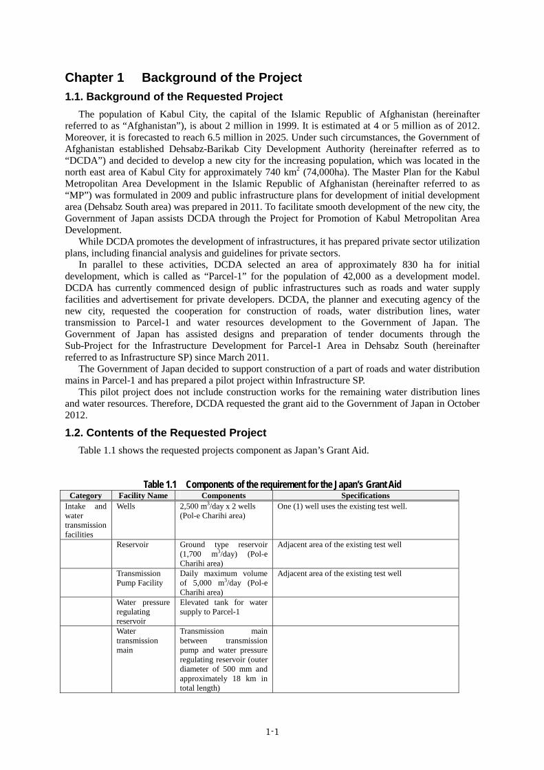
1.2. Contents of the Requested Project Table 1.1 shows the requested projects component as Japan’s Grant Aid.
Table 1.1 Components of the requirement for the Japan’s Grant Aid
Category Facility Name Components Specifications Intake and water transmission facilities
Wells 2,500 m3/day x 2 wells (Pol-e Charihi area)
One (1) well uses the existing test well.
Reservoir Ground type reservoir (1,700 m3/day) (Pol-e Charihi area)
Adjacent area of the existing test well
Transmission Pump Facility
Daily maximum volume of 5,000 m3/day (Pol-e Charihi area)
Adjacent area of the existing test well
Water pressure regulating reservoir
Elevated tank for water supply to Parcel-1
Water transmission main
Transmission main between transmission pump and water pressure regulating reservoir (outer diameter of 500 mm and approximately 18 km in total length)

1-2
1.3. Environmental and Social Consideration
Outline of the Project Components 1.3.1 This project consists of four (4) main components as follows:
Production wells, Pumping station 2 production wells, water reservoir and pumping station
Water transmission main Water pipes between the production wells and the water pressure regulating reservoir. Basically it is installed along the existing road.
Water pressure regulating reservoir Elevated water reservoir to distribute the water to Percel-1
Principal water distribution lines A part of water distribution lines which deriver water to city blocks in the Percel-1 and will be a basic framework. The distribution lines will be constructed under the planned road. Therefore, the pipelines laying works will not cause significant environmental impacts. Environmental and social consideration for the road construction has been under progress as a part of Parcel-1 development project. JICA rated its environmental impact as category A in accordance with the JICA’s guidelines for environmental and social consideration (April 2004). Advisory Committee of Environmental and Social Considerations has already approved necessary environmental processes.
Environmental and Social Conditions 1.3.2 The basic environmental and social condition for each project component is shown in Table 1.2.
Table 1.2 Basic Environmental and Social Condition
Classification Production wells, Pumping station
Water transmission main
Water pressure regulating reservoir
Major water distribution lines
Land use Wheat field (PW-1) Open area beside the existing road (PW-2)
Existing road Raw land which locates about 700m outside of the Percel-1
Planned road
Natural Environment
Important fauna/flora does not exit
Important fauna/flora does not exit
Important fauna/flora does not exit Dry river exists near the location
Important fauna/flora does not exit
Social environment
Private houses locate closer to the area
2 huts (shop and guard house) exist in the ROW*, however resettlement is not necessary by modification of the pipe route.
Private houses do not exist. Brick factories scatter at a distance from the location.
Resident houses and brick factories scatter in the Percel-1
* ROW: Right of Way
Legal Framework for Environmental and Social Consideration in Afghanistan 1.3.3 NEPA (National Environmental Protection Agency) is responsible for regulating regarding
conservation and restoration of environment, monitoring and compliance of environmental laws. As a procedure for environmental permit, project proponent submits the screening report to NEPA upon implementation of the project. The target project is categorized as one of following categories depending on the possible impacts1.
Category A It is likely to have significant adverse environmental impacts that are sensitive, diverse, or
1 Administrative Guidelines for the Preparation of Environmental Impact Assessment, March 2007, NEPA

1-3
unprecedented, and affects and area broader than the sites or facilities subject to physical works. Category B
The potential adverse environmental impacts on human populations or environmentally sensitive areas (e.g. wetlands, forests, grasslands and other natural habitats) are less adverse than those of Category A projects. These impacts are site-specific. Few are irreversible.
Category C It is likely to have minimal or no adverse environmental impacts.
Based on the screening report, categorization of the project and public disclosure, NEPA will certify the environmental permit or require further EIA (Environmental Impact Assessment) study to the project proponent. Even though the environmental permit is certified, the project proponent will be required the submission of EMP (Environmental Management Plan) and implementation of the EMP.
If further EIA study is required, the scope of the EIA and covered area will also be provided by NEPA. Figure 1-1 shows the procedure for obtaining environmental permit.
Source: Prepared by the Study Team based on the NEPA guideline
Figure 1-1 Procedure for Environmental Permit
Alternative Analysis 1.3.4 Although snow-melt-runoff water flow into the Dehsabz area temporarily throughout year, annual
precipitation is 300mm and recharge capability of the area is low. Therefore, securement of steady

1-4
water resource in the area is difficult. Thus water resource from other region is necessary for supply of drinking water to the area.
Water conveyance/transmission from Sayed fan has been planned, but the implementation is considered take long because it is still on feasibility study.
If this project is not implemented, the plan of DCDA (42,000 of population in the year 2015) will not be sustainable due to lack of water resource and development of Percel-1 will no-longer exist.
For this reason, implementation of this project is considered as appropriate. Pol-e-Charkhi area has been confirmed as suitable water resource by JICA Groundwater
sub-project, the Sub-Project for Groundwater Survey for Dehsabz South Development Area (hereinafter referred as to “groundwater SP”). Water transmission main will be installed under the existing road, which is cheaper and less environmental impact.
Screening Report and Project Categorization 1.3.5 In June 2012, DCDA submitted the IEE (Initial Environmental Examination) report to NEPA. It
includes environmental screening format which concludes that the project shall be categorized as ‘B’. Table 1.3 shows the screening checklist in NEPA format.
Table 1.3 Screening Checklist FORESEEABLE IMPACT Yes No 1 Will the project involve construction of any type of structure (building, check dam,
walls, etc)? x
2 Will the project involve the construction or repair of roads or trails? x 3 Will the project involve the use, involve plans to use or training in the use of any
chemical compounds such as pesticides (including neem), herbicides, paint, varnish, lead-based products, etc?
x
4 Involve the construction of repair of irrigation systems? x 5 Involve the construction or repair of fish ponds? x 6 Involve the disposal of used engine oil? x 7 Will the project involve implementation of timber management4 or extraction of forest
products? x
8 Are there any potentially sensitive terrestrial or aquatic areas near the project site, including protected areas?
x
9 Does the activity impact upon wildlife, forest resources, or wetlands? x 10 Will the activities proposed generate airborne gases, liquids, or solids (i.e. discharge
pollutants) x
11 Will the waste generated during or after the project impact on neighboring surface or ground water?
x
12 Will the activity result in clearing of forest cover? x 13 Will the activity contribute to erosion?
x
14 Is the activity incompatible with existing land use in the vicinity? x 15 Will the activity contribute to displace housing? x 16 Will the activity affect unique geologic or physical features? x 17 Will the activity contribute to change in the amount of surface water in any body? x 18 Will the activity deal with mangroves and coral reefs? x 19 Will the activity expose people or property to flooding? x 20 Will the activity contribute substantial reduction in the amount of ground water
otherwise available for public water supplies? x
21 Will the activity create objectionable odors? x 22 Will the activity violate air standard? x 23 Does the activity e.g. infrastructure improvements require local planning
permission(s)? x
24 Does the activity meet the national building code (e.g. infrastructure improvements)? x 25 Is the activity incompatible with existing land use? x 26 Will the project activities create conditions encouraging an increase of waterborne
diseases or populations of disease carrying vectors? x

1-5
FORESEEABLE IMPACT Yes No 27 Will the activity generate hazards or barriers for pedestrians, motorists or persons with
disabilities? x
28 Will the activity increase existing noise levels? x 29 Will the project involve the disposal of syringes, gauzes, gloves and other biohazard
medical waste? x
After environmental review, activities determined to have no significant adverse impacts by appropriate mitigation and monitoring. Negative determination(s) with conditions. B’ Category
Source: IEE report (DCDA)
The IEE was received and NEPA issued environmental permission in December 2012. This project is also categorized as “B” by JICA Guidelines for Environmental and Social
Considerations (April 2004) by the following reasons. The areas for the water resource and for the water pressure regulating reservoir are limited and
small. Water transmission and/or distribution pipes are installed under roads within the right of way,
which is considered as improvement of existing road. Although 2 huts (shop and guard hut) exist in the right of way of the existing road, resettlement
can be avoided by ingenuity on the installation of the water pipe. Other adverse impacts on social environment are also minor and reversible with proper mitigation
measures. Some impacts on natural environment and pollution are expected during construction; however,
they can be controlled and minimized with proper measures.
Scoping 1.3.6 Social and environmental consideration based on a result of the scoping is shown in Table 1.4

1-6
Table 1.4 Scoping Matrix
Plan
Land
Acq
uisi
tion,
Loss
of S
truct
ure
or A
gric
ultu
re
Ope
ratio
n of
con
stru
ctio
n ve
hicl
e
Wel
l Dril
ling
Res
ervo
irs
Pum
p Fa
cilit
y
Tran
smis
sion
Mai
n
Wat
er P
ress
ure
Reg
ulat
ing
Res
ervo
ir
Pum
ping
Wat
er T
rans
porta
tion
1 Air Pollution -B D -B -B -B D -B -B D D Increase in dust and exhaustion gas during
construction
2 Water Pollution -B D D -B D D -B D D D Potential generation of turbidity during drilling
and pipe laying works
3 Waste Management -B D D -B -B D -B -B D D Surplus soil during excavation and pipe laying
works
4 Soil Contamination -B D D -B -B D -B D D D Potential soil contamination during excavation
and pipe laying works
5 Noise & Vibration -B D -B -B -B -B -B -B -C -C Generation of noise and vibration due to
construction works and operation of pumps
6 Land Subsidence -C D D -C D D D D -C D Potential land subsidence due to over pumping
7 Offensive Odor D D D D D D D D D D Offensive odor is not foreseen
8 Sediments D D D D D D D D D D Contamination of sediment is not foreseen
1 Protected Area D D D D D D D D D D No protected area near the Project site
2 Ecosystem -C D D D D D D -C D D Land acquisition may be required depending on
the Project location
3 Hydrology -C D D D D D -C D D D Construction works are along the roads, thus
impact is minor
4 Geology andGeography
D D D D D D D D D D No large scale works are planned
5 Rivers -C D D D D D -C D D D Pipeline laying works may impact on this
component
6 Groundwater -C D D -C D D -C D -C D Potential impact during excavation and pumping
7 Meteorology D D D D D D D D D D No impact is foreseen
8 Landscape -B D D D D D D -B D D Necessary to harmonize with surrounding
environment
9 Climate Change D D D D D D D D D D No impact is foreseen
1 Resettlement -B D D D D D -B D D D Relocation of shops within ROW is necessary
2 Economic Activity -B D D D D D -B D D D Relocation of shops within ROW is necessary
3 Land Use andNatural
D D D D D D D D D D No impact is foreseen
4 Splitting ofcommunities
D D D D D D D D D D No impact is foreseen
5 Transportation +-B D D D D D -B D D +BTemporary impact on traffic such as traffic jam.
Test well will be used by local people after
operation.
6 Poverty &Minorities
D D D D D D D D D D No impact is foreseen
7 Unfairdistribution
D D D D D D D D D D No impact is foreseen
8 Cultural Heritage D D D D D D D D D D No impact is foreseen
9 Confliction D D D D D D D D D D No impact is foreseen
10 Water Right -C D D D D D D D D -C Prior adjustment is required
11 Hygiene -C D D D D D D D -C D Potential impact on surrounding wells due to
pumping
12 HIV/AIDS, etc. D D D D D D D D D D No impact is foreseen
13 LaborEnvironment
-B D D D D D -B D D D Protection of labor condition is required
Others 1 Accident -B D -B D D D -B D D D Risk of accident due to increase of construction
vehicle
Pollu
tion
Nat
ural
Env
ironm
ent
Soci
al E
nviro
nmen
t
Evaluation: A: Significant Impact, B: Some Impact, C: Degree of Impact is unknown and further investigation is required, and D: Impact is minor and no furtherinvestigation is required.+: Positive Impact and -: Negative ImpactThe parameters of this scoping were set based on JICA's guidelines.
Subj
ect
Para
met
ers
Tota
l Eva
luat
ion
Construction Operation
Reason

1-7
TOR for Environmental and Social Surveys 1.3.7 A study for environmental and social consideration shown in Table 1.5 was conducted based on the
result of the scoping.
Table 1.5 TOR for environmental and social surveys Subject Target Parameters Study method
Pollution Air pollution Situation of air pollution Interview, observation Water pollution Water area and condition Observation, existing information Waste management Waste management Interview, existing information Noise & Vibration Present condition Observation, existing information Land subsidence Present condition Existing information
Natural environment
Ecosystem Rare fauna and flora Existing information Hydrology Creeks Observation, existing information Rivers Present situation Observation, existing information Groundwater Water level, water quality Existing information Landscape Landscape change Existing information,
Social environment
Resettlement Necessity Observation Economic activity Situation Observation Transportation Traffic Existing information Observation Water right Water right Interview Hygiene Safety measures Existing information Labor environment Safety measures Existing information
Others Accident Safety measures Existing information
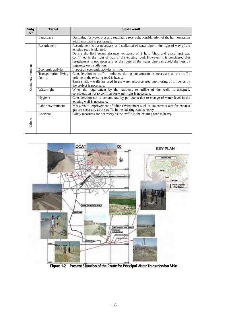
Result of the Study on Environmental and Social Consideration 1.3.8 The study was conducted from the end of November 2012 to the beginning of December 2012
based on the TOR mentioned above. The results are summarized in Table 1.6. The present situation alongside the route for water transmission main is shown in Figure 1-2.
Table 1.6 Result of the study on Environmental and social Consideration Subject
Target Study result
Pollu
tion
Air pollution Air pollution is not recognized in the water resource area where resident houses exist. Consideration for measures to pollution control is necessary during the construction phase. Traffic is heavy on the existing road for principal water transmission main. It is considered the environmental impact by the construction is small. No resident house exists. Consideration for exhaust gas from construction machinery is necessary.
Water pollution Kabul river is turbid due to other construction works. However, consideration for discharging water by the construction on this project is necessary.
Waste management Surplus soil is planned to be utilized as ground leveling. Thus the volume of waste is small. In case dumping of waste is necessary, the waste will be transported to the designated dumping site by Kabul city. Therefore the impact by waste is not significant.
Noise & Vibration Countermeasure to noise and vibration on the construction in the water resource area is necessary.
Land subsidence
Pumping water volume is determined within the recoverable range of water level. Therefore it is considered the possibility of land subsidence is quite low.
Nat
ural
env
ironm
ent Ecosystem Land use for the water resource area is field, existing road for water pipe and arid
land for water pressure regulating reservoir. Rare fauna and flora is not recognized. Therefore major impact is not considered.
Hydrology Consideration not to modify the existing topography on construction, as a dry river exists close to the water pressure regulating reservoir.
Rivers Kabul river is turbid due to other construction. However consideration for discharging water by the construction on this project is necessary.
Ground water The possibility of impact to the water quality of existing wells and ground water is considered low. However monitoring of water level is necessary.
1-8
Subject
Target Study result
Landscape Designing for water pressure regulating reservoir, consideration of the harmonization with landscape is performed.
Soci
al e
nviro
nmen
t
Resettlement Resettlement is not necessary as installation of water pipe in the right of way of the existing road is planned. During the field reconnaissance, existence of 2 huts (shop and guard hut) was confirmed in the right of way of the existing road. However, it is considered that resettlement is not necessary as the route of the water pipe can avoid the huts by ingenuity on installation.
Economic activity Impact on economic activity is little. Transportation, living facility
Consideration to traffic hindrance during construction is necessary as the traffic volume in the existing road is heavy. Since shallow wells are used in the water resource area, monitoring of influence by the project is necessary.
Water right When the requirement by the residents to utilize of the wells is accepted, consideration not to conflicts for water right is necessary.
Hygiene Consideration not to contaminate by pollutants due to change of water level in the existing well is necessary.
Labor environment Measures to improvement of labor environment such as countermeasure for exhaust gas are necessary as the traffic in the existing road is heavy.
Oth
ers
Accident Safety measures are necessary as the traffic in the existing road is heavy.
Figure 1-2 Present Situation of the Route for Principal Water Transmission Main
1-9
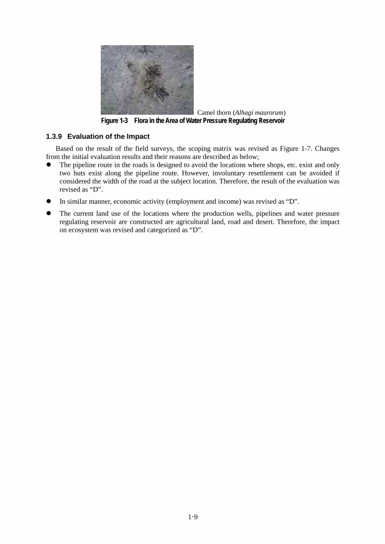
Camel thorn (Alhagi maurorum) Figure 1-3 Flora in the Area of Water Pressure Regulating Reservoir
Evaluation of the Impact 1.3.9 Based on the result of the field surveys, the scoping matrix was revised as Figure 1-7. Changes
from the initial evaluation results and their reasons are described as below; The pipeline route in the roads is designed to avoid the locations where shops, etc. exist and only
two huts exist along the pipeline route. However, involuntary resettlement can be avoided if considered the width of the road at the subject location. Therefore, the result of the evaluation was revised as “D”.
In similar manner, economic activity (employment and income) was revised as “D”.
The current land use of the locations where the production wells, pipelines and water pressure regulating reservoir are constructed are agricultural land, road and desert. Therefore, the impact on ecosystem was revised and categorized as “D”.

1-10
Table 1.7 Result of Impact Assessment
Mitigation Measures and Cost 1.3.10 This section summarizes the mitigation measures described in the IEE by DCDA (Table 1.8),
anticipated environmental impacts during construction and operation phases and their mitigation measures based on the field survey. The result of the examination is shown in Table 1.9 and Table 1.10.
Plan
ning
/Con
stru
ctio
n
Ope
ratio
n
Plan
ning
/Con
stru
ctio
n
Ope
ratio
n
1 Air Pollution -B D -B D Increase in dust and exhaustion gas during construct ion
2 Water Pollution -B D -B D Potential generat ion of turbidity during drilling and pipe laying works
3 Waste Management -B D -C D Surplus soil during excavat ion and pipe laying works
4 Soil Contamination -B D -B D Potential soil contamination during excavation and pipe laying works
5 Noise & Vibration -B -C -B -C Generat ion of noise and vibration due to construction works and operation of pumps
6 Land Subsidence -C -C -C -C Potential land subsidence due to over pumping
7 Offensive Odor D D D D Offensive odor is not foreseen
8 Sediments D D D D Contamination of sediment is not foreseen
1 Protected Area D D D D No protected area near the Project site
2 Ecosystem -C D D D Impact is not considered
3 Hydrology -C D -C D Consideration not to modify the topography of a dry river is necessary
4 Geology andGeography D D D D No large scale works are planned
5 Rivers -C D -C D Pipeline laying works may impact on this component
6 Groundwater -C -C -C -C Potential impact during excavation and pumping
7 Meteorology D D D D No impact is foreseen
8 Landscape -B D D D Necessary to harmonize with surrounding environment
9 Climate Change D D D D No impact is foreseen
1 Resettlement -C D D D Relocat ion of shops within ROW may is not necessary by ingenuity of construction
2 Economic Activity -C D D D No impact is foreseen with the same reason as above
3 Land Use andNatural Resources D D D D No impact is foreseen
4 Splitting ofcommunities D D D D No impact is foreseen
5 Transportation -B +B -B +BTemporary impact on t raffic such as traffic jam. Test well will be used by local peopleafter operation.
6 Poverty &Minorities D D D D No impact is foreseen
7 Unfair distributionof benefit D D D D No impact is foreseen
8 Cultural Heritage D D D D No impact is foreseen
9 Confliction D D D D No impact is foreseen
10 Water Right D -C -C -C Prior adjustment is required
11 Hygiene D -C -C -C Potential impact on surrounding wells due to pumping
12 HIV/AIDS, etc. D D D D No impact is foreseen
13 LaborEnvironment -B D -B D Protect ion of labor condit ion is required
Others 1 Accident -B D -B D Risk of accident due to increase of construction vehicle
Nat
ural
Env
ironm
ent
Soci
al E
nviro
nmen
t
Evaluation: A: Significant Impact, B: Some Impact, C: Degree of Impact is unknown and further investigation is required, and D: Impact is minor and no furtherinvestigation is required.+: Positive Impact and -: Negative ImpactThe parameters of this scoping were set based on JICA's guidelines.
Subj
ect
Para
met
ers
Evaluation onscoping
Evaluation based onthe study
Reason
Pollu
tion

1-11
Table 1.8 Potential Impacts and Mitigation Measures No. Activities Potential Impacts Measures of Mitigation
1 Installation of materials and equipment at site
Air Quality Noise and vibration Odor Ecosystem Topography/Geology Work Environment Traffic Accident
Transportation of equipment and machinery will be well planned. Modification of topography will be minimized so that impact to
ecosystem is small.
2 Drilling of wells and construction of reservoir, warehouse
Air Quality Water Quality Ground Water Waste Soil Noise and vibration Odor Hydrology Livelihood/Living Work Environment
Measures for dispersion of dust will be considered. Water quality and water level in the wells at neighbor households will
be monitored. Waste and dredged soil will be dumped to the official dump site. Noise and vibration by construction will be minimized. Safety programs and training to the workers will be planned.
3 Installation of pumps Noise and vibration Work Environment Accident
Noise and vibration by construction will be minimized. Safety programs and training to the workers will be planned.
4 Pumping of water
Water Quality Ground Water Noise/Vibration Ground Subsidence Livelihood/Living
Water quality and water level of the wells at neighbor households will be monitored.
Measures to noise and vibration from pumps will be considered. Water level in the Kabul River will be monitored. Ground levels at major locations will be monitored.
5 Transmission of water Noise/Vibration Measures to noise and vibration from pumps will be considered.6 Resettlement Loss of opportunity of merchandise Proper compensation will be considered.
7 Installation of materials/heavy machinery.
Air Quality Noise/Vibration Odor Work Environment Traffic Accident
Transportation of equipment and machinery will be well planned. Programs and training to workers will be planned. Person for traffic control will be hired.

1-12
No. Activities Potential Impacts Measures of Mitigation
8 Installation of main
Air Quality Water Quality Waste Soil Noise/Vibration Odor Work Environment Traffic Accident
Measures to dispersion of dust, noise/vibration and odor will be considered.
Waste and surplus soil will be dumped to the official dump site. Safety programs and training to the workers will be planned. Person for traffic control will be hired.
Source: IEE Report (DCDA)
1-13
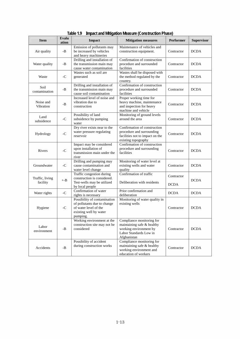
Table 1.9 Impact and Mitigation Measure (Construction Phase) Item Evalu
ation Impact Mitigation measures Performer Supervisor
Air quality -B Emission of pollutants may be increased by vehicles and heavy machineries
Maintenance of vehicles and construction equipment.
Contractor DCDA
Water quality -B Drilling and installation of the transmission main may cause water contamination
Confirmation of construction procedure and surrounded facilities
Contractor DCDA
Waste -C Wastes such as soil are generated
Wastes shall be disposed with the method regulated by the country.
Contractor DCDA
Soil contamination -B
Drilling and installation of the transmission main may cause soil contamination
Confirmation of construction procedure and surrounded facilities
Contractor DCDA
Noise and Vibration -B
Increased level of noise and vibration due to construction
Proper working time for heavy machine, maintenance and inspection for heavy machine and vehicle
Contractor DCDA
Land subsidence -C
Possibility of land subsidence by pumping water
Monitoring of ground levels around the area Contractor DCDA
Hydrology -C
Dry river exists near to the water pressure regulating reservoir
Confirmation of construction procedure and surrounding facilities not to impact on the existing topography
Contractor DCDA
Rivers -C
Impact may be considered upon installation of transmission main under the river
Confirmation of construction procedure and surrounding facilities Contractor DCDA
Groundwater -C Drilling and pumping may cause contamination and water level change
Monitoring of water level at existing wells and water quality
Contractor DCDA
Traffic, living facility +-B
Traffic congestion during construction is considered. Test-wells may be utilized by local people
Confirmation of traffic Deliberation with residents
Contractor DCDA
DCDA
Water rights -C Confirmation of water rights is necessary
Prior confirmation and deliberation DCDA DCDA
Hygiene -C
Possibility of contamination of pollutants due to change of water level of the existing well by water pumping.
Monitoring of water quality in existing wells
Contractor DCDA
Labor environment -B
Working environment at the construction site may not be considered
Compliance monitoring for maintaining safe & healthy working environment by Labor Standards Low in Afghanistan
Contractor DCDA
Accidents -B
Possibility of accident during construction works
Compliance monitoring for maintaining safe & healthy working environment and education of workers
Contractor DCDA

1-14
Table 1.10 Impact and Mitigation Measure (Operation) Item Evalu
ation Impact Mitigation measures Performer Supervisor
Noise and Vibration -C
Increased level of noise and vibration by operation of water pump
Monitoring at pumping area boundary AUWSSC AUWSSC
Land subsidence -C Water pumping may cause
ground subsidence Monitoring of ground level AUWSSC AUWSSC
Ground water -B Water level change and degradation of water quality by water pumping
Monitoring of water levels at existing wells and water quality
AUWSSC AUWSSC
Water rights -C Water right dispute Prior confirmation and deliberation DCDA DCDA
Hygiene -C Contamination of well by pumping
Monitoring of water quality at existing wells AUWSSC AUWSSC
Environmental Management and Monitoring Plans 1.3.11 It can be expected that most of influences on natural and social environment of this project is
limited only during construction as the result of scooping. Monitoring plans for 2 phases, namely the construction phase and operation phase, are shown in Table 1.11 and Table 1.12, respectively.
Necessary items for the monitoring and their methods, frequency, etc. shall be reviewed in consideration of necessity and appropriateness in Afghanistan.
Table 1.11 Environmental Monitoring Plan(Construction phase) Impact Monitoring item Monitoring method Location Frequency Responsible
organization Air Quality Dust Visual observation Target area Everyday Contractor
Water Quality Turbidity Visual observation Target area Everyday Contractor Wastes Material, volume Visual observation Target area Everyday Contractor
Noise and Vibration Noise and Vibration Measurement by equipment
Boundary of the area, road side 2 times/month Contractor
Hydrology Turbid water,
change of water flow
Visual observation Target area Everyday Contractor
River Turbidity Visual observation Target area Everyday Contractor
Ground water
Water level, pH, Conductivity,
Turbidity, color Odor, Coliform
Measurement by equipment and visual
observation
Existing wells around the water
resource 1 time/month Contractor
Traffic, living facility Traffic congestion, utilization of well
Interview, visual observation Target area 1time/month Contractor
DCDA Water rights Water rights Interview Target area Occasionally DCDA
Public health pH, Conductivity, Turbidity, color Odor, Coliform
Measurement by equipment and visual
observation (can be combined with the monitoring for the
‘Ground water’)
Existing wells around the water
resource 1 time/month Contractor
Working environment Safety and health management
Confirmation by monthly progress
report Target area 1 time/month Contractor
Accident Safety and health management
Confirmation by monthly progress
report Target area 1 time/month Contractor

1-15
Table 1.12 Environmental Monitoring Plan(Operation phase) Impact Monitoring item Monitoring method Location Frequency Responsible
organization
Noise and Vibration Noise and Vibration
Measurement Interview to residents
Surrounded area of water resource 4 times/year AUWSSC
Ground water
Water level, pH, Conductivity,
Turbidity, color Odor, Coliform
Measurement by equipment and visual
observation
Existing wells around the water
resource 4 times/year AUWSSC
Ground subsidence Ground level Measurement Surrounded area of water resource 4 times/year AUWSSC
Stakeholders Meeting 1.3.12 Table 1.13 shows the summary of the first stakeholders’ meeting held on 23 November, 2011.
Table 1.13 Summary of First Stakeholders’ Meeting 1st meeting Date November 23rd, 2011 Time 10:10 – 11:45 Venue Afghanistan National Standard Authority (ANSA) Number of participants About 40 Agenda - Implementation of New City Plan in Dehsabz
- Targeted Permanent and Temporary Water Resources for the New City Plan
- The positive and negative impacts of water distribution on Pole Charkhi area.
- Explanation Concerning 4 Candidate sites for Temporary Water Transmission.
- Selection possibility of a New Well Construction Site in Local People's Land with the Agreement of Local People.
Major discussion - Basically no opposition to the project - Concern of affection to water levels of existing wells - Expectation of rehabilitation of the existing road by the project - Request for construction of bridge
Source: Minutes of Meeting prepared by DCDA
The followings were clarified as a result of individual interview after the meeting. - Not all residents were acknowledged about the Project
- Residents expects much profits from the Project
- There are two groups which politically conflict each other
These might be become a potential risks without countermeasures. Therefore DCDA shall take into consideration these and plan to have further stakeholder meeting for border notification and consensus building with sincere answers to requirements from residents.
1.4. Land Acquisition and Resettlement
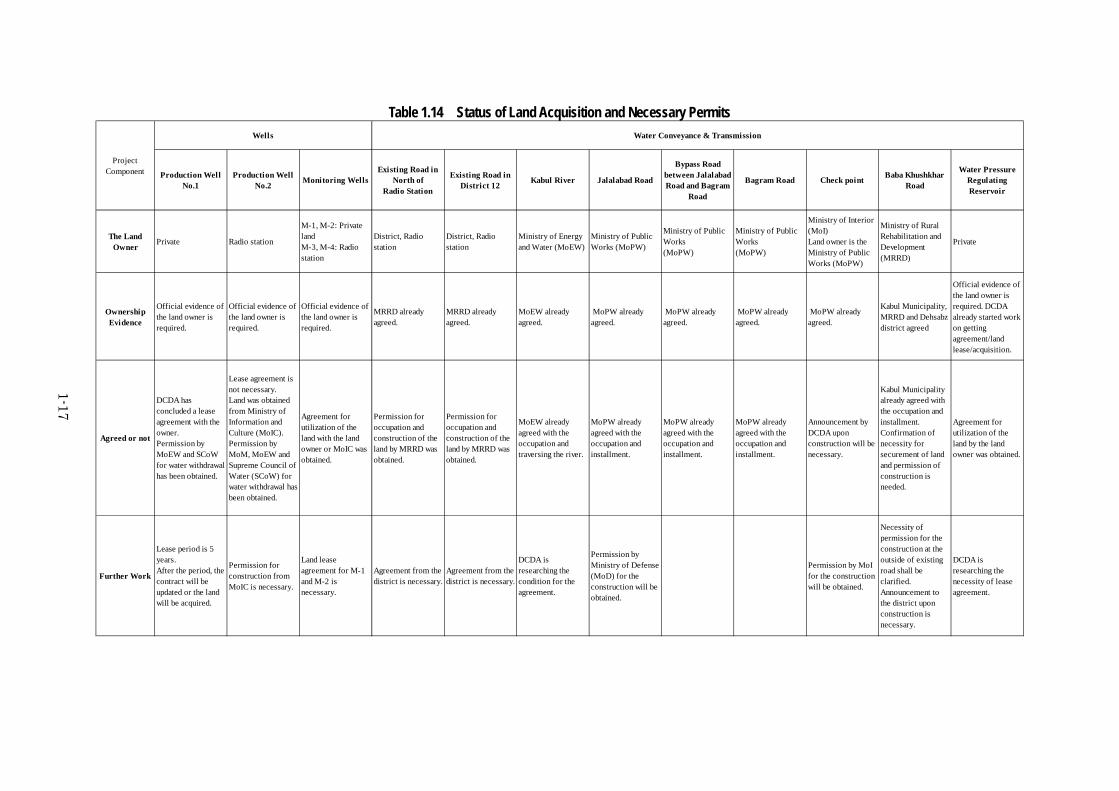
Necessity of Land Acquisition and Resettlement 1.4.1 Status of land acquisition on each component is as follows. Table 1.14 summarizes the status of
land acquisition and necessary of permits. DCDA is supposed to secure necessary land for the project and obtain permits for occupation/construction upon implementation of the project.

1-16
Water resource area (1)The land owned by the National Radio Station was previously planned to be used as the site for
water resource facilities. However, it was canceled due to possibility of interference to radio wave by the water resource facility and security reason.
After the cancelation, DCDA had land lease contract for the 1st well out of planned 2 wells at the north of the Radio Station. As for the 2nd well site, the candidate location is at the east of the Radio Station. DCDA has acquired permission for lease and use of the site from the Radio Station and the Ministry of Information and Culture.
Out of 4 monitoring wells, 2 candidate locations are owned by the Radio Station (Ministry of Information and Culture) and DCDA has acquired permission for use of the land. Other 2 candidate sites are private property. DCDA has obtained permission for the use of the site from the owners and has currently examining the conditions for lease contracts.
Area for the water transmission main (2)Major parts of the water transmission main is planned to be installed at the right of way of the
existing road. The land acquisition is not necessary for the mentioned parts, although permit for occupation and construction is necessary. According to DCDA, permits have been obtained from the administrator of the road such as Ministry of Public Works for implementation of construction works. DCDA acquired permission from the Ministry of Rural Rehabilitation and Development (North part of the Radio Station and Road in District 12) and the Ministry of Public Works (Jalalabad road and Bagram road). Furthermore, DCDA expects to obtain permissions from the communities along the road in District 12 and the road locates in the northern part of the Radio Station. The Ministry of Energy and Water agreed the work for laying pipelines at the bottom of Kabul River. DCDA has currently prepared discussion with the Ministry of Defense and the Ministry of Interior for check points in Bagram road and Jalalabad road.
DCDA is planning to install the water transmission main under the Baba Khushkhar road, which located between Bagram road and the water pressure regulating reservoir. Pipelines will be laid within the area of the right of the way of the existing road and, therefore, additional land acquisition is not required. However, it may be required to clarify necessity of permission in some areas. Thus, adequate information disclosure to public before construction works is necessary.
Area for the water pressure regulating reservoir (3)The candidate location for the water pressure regulating reservoir is determined. The owner of the
land has agreed to allocate the land for the water supply facility. DCDA has currently processed lease contract with the owner of the site.
Principal water distribution lines (4)The route will be in the right of way. After land acquisition for road is completed, adverse impacts
for installation of the pipelines is not foreseen. DCDA has been investigating the land owner.
1-17
Table 1.14 Status of Land Acquisition and Necessary Permits
Production WellNo.1
Production WellNo.2 Monitoring Wells
Existing Road inNorth of
Radio Station
Existing Road inDistrict 12 Kabul River Jalalabad Road
Bypass Roadbetween JalalabadRoad and Bagram
Road
Bagram Road Check point Baba KhushkharRoad
Water PressureRegulatingReservoir
The LandOwner
Private Radio station
M-1, M-2: PrivatelandM-3, M-4: Radiostation
District, Radiostation
District, Radiostation
Ministry of Energyand Water (MoEW)
Ministry of PublicWorks (MoPW)
Ministry of PublicWorks(MoPW)
Ministry of PublicWorks(MoPW)
Ministry of Interior(MoI)Land owner is theMinistry of PublicWorks (MoPW)
Ministry of RuralRehabilitation andDevelopment(MRRD)
Private
OwnershipEvidence
Official evidence ofthe land owner isrequired.
Official evidence ofthe land owner isrequired.
Official evidence ofthe land owner isrequired.
MRRD alreadyagreed.
MRRD alreadyagreed.
MoEW alreadyagreed.
MoPW alreadyagreed.
MoPW alreadyagreed.
MoPW alreadyagreed.
MoPW alreadyagreed.
Kabul Municipality,MRRD and Dehsabzdistrict agreed
Official evidence ofthe land owner isrequired. DCDAalready started workon gettingagreement/landlease/acquisition.
Agreed or not
DCDA hasconcluded a leaseagreement with theowner.Permission byMoEW and SCoWfor water withdrawalhas been obtained.
Lease agreement isnot necessary.Land was obtainedfrom Ministry ofInformation andCulture (MoIC).Permission byMoM, MoEW andSupreme Council ofWater (SCoW) forwater withdrawal hasbeen obtained.
Agreement forutilization of theland with the landowner or MoIC wasobtained.
Permission foroccupation andconstruction of theland by MRRD wasobtained.
Permission foroccupation andconstruction of theland by MRRD wasobtained.
MoEW alreadyagreed with theoccupation andtraversing the river.
MoPW alreadyagreed with theoccupation andinstallment.
MoPW alreadyagreed with theoccupation andinstallment.
MoPW alreadyagreed with theoccupation andinstallment.
Announcement byDCDA uponconstruction will benecessary.
Kabul Municipalityalready agreed withthe occupation andinstallment.Confirmation ofnecessity forsecurement of landand permission ofconstruction isneeded.
Agreement forutilization of theland by the landowner was obtained.
Further Work
Lease period is 5years.After the period, thecontract will beupdated or the landwill be acquired.
Permission forconstruction fromMoIC is necessary.
Land leaseagreement for M-1and M-2 isnecessary.
Agreement from thedistrict is necessary.
Agreement from thedistrict is necessary.
DCDA isresearching thecondition for theagreement.
Permission byMinistry of Defense(MoD) for theconstruction will beobtained.
Permission by MoIfor the constructionwill be obtained.
Necessity ofpermission for theconstruction at theoutside of existingroad shall beclarified.Announcement tothe district uponconstruction isnecessary.
DCDA isresearching thenecessity of leaseagreement.
ProjectComponent
Wells Water Conveyance & Transmission
1-18
Legal Framework on Land Acquisition and Resettlement 1.4.2 There had been no specific resettlement policy in Afghanistan till the recent year, but a
comprehensive land policy was approved in 2007 by the cabinet. The Constitution of Afghanistan, which was ratified in early 2004, has three articles that closely relate to compensation and resettlement. For public interest purposes, such as the establishment/construction of public infrastructure or for acquisition of land with cultural or scientific values, land of higher agricultural productivity, large gardens, the Land Acquisition Law (LAL) enacted in 2009 regulates procedures of lands acquisition of private lands.
The RAP (Resettlement Action Plan) annexed by the EIA for Percel-1 development refers to JICA guideline and World Bank OP4.12 to prepare the RAP for land acquisition and resettlement.
During the field reconnaissance along the planned route for the water transmission main, it was realized that the route is planned to avoid shops within the right of way and the existence of 2 huts (shop and guard hut) was confirmed. The width of the road at the locations of the huts is large and it is considered that the removal of the huts can be avoided by ingenuity on installation of the water pipe. Therefore relocation of the huts is not necessary.
Since resident houses do not exist in the right of way of Baba Khushkhar road and in the candidate area of the water pressure regulating reservoir, there is no possibility of resettlement.
Stakeholders’ Meeting 1.4.3 Although resettlement is not foreseen in this Project, explanation of the project such as project
period and contents to stakeholders is necessary. The outline of the project was explained on the first stakeholder meeting described above and the
project was basically agreed. However, further explanation after the detailed design is completed is considered necessary.
1.5. Others
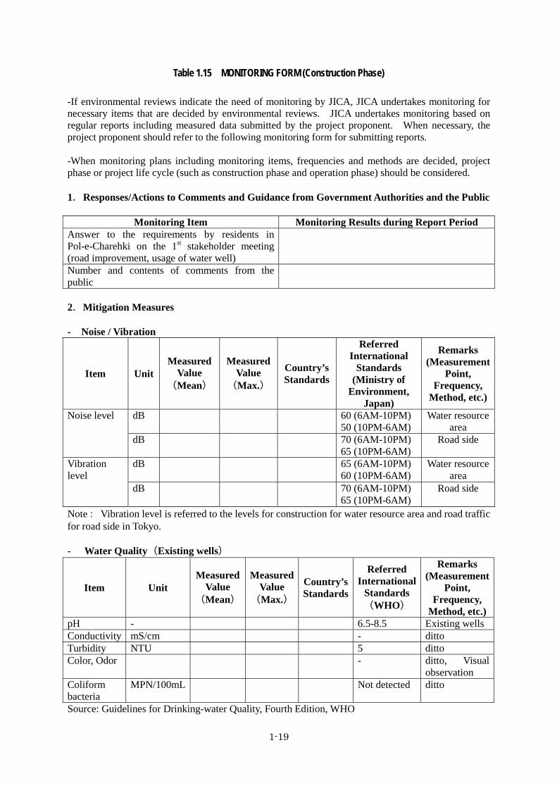
Monitoring Form 1.5.1 Monitoring forms for environmental impacts on this project are shown in Table 1.14 and Table
1.15.
1-19
Table 1.15 MONITORING FORM (Construction Phase)
-If environmental reviews indicate the need of monitoring by JICA, JICA undertakes monitoring for necessary items that are decided by environmental reviews. JICA undertakes monitoring based on regular reports including measured data submitted by the project proponent. When necessary, the project proponent should refer to the following monitoring form for submitting reports. -When monitoring plans including monitoring items, frequencies and methods are decided, project phase or project life cycle (such as construction phase and operation phase) should be considered. 1.Responses/Actions to Comments and Guidance from Government Authorities and the Public
Monitoring Item Monitoring Results during Report Period Answer to the requirements by residents in Pol-e-Charehki on the 1st stakeholder meeting (road improvement, usage of water well)
Number and contents of comments from the public
2.Mitigation Measures - Noise / Vibration
Item Unit Measured
Value (Mean)
Measured Value
(Max.)
Country’s Standards
Referred International
Standards (Ministry of
Environment, Japan)
Remarks (Measurement
Point, Frequency,
Method, etc.)
Noise level dB 60 (6AM-10PM) 50 (10PM-6AM)
Water resource area
dB 70 (6AM-10PM) 65 (10PM-6AM)
Road side
Vibration level
dB 65 (6AM-10PM) 60 (10PM-6AM)
Water resource area
dB 70 (6AM-10PM) 65 (10PM-6AM)
Road side
Note: Vibration level is referred to the levels for construction for water resource area and road traffic for road side in Tokyo. - Water Quality(Existing wells)
Item Unit Measured
Value (Mean)
Measured Value
(Max.)
Country’s Standards
Referred International
Standards (WHO)
Remarks (Measurement
Point, Frequency,
Method, etc.)pH - 6.5-8.5 Existing wells Conductivity mS/cm - ditto Turbidity NTU 5 ditto Color, Odor - ditto, Visual
observation Coliform bacteria
MPN/100mL Not detected ditto
Source: Guidelines for Drinking-water Quality, Fourth Edition, WHO

1-20
- Hydrology (Water Level: River/Wells)
Item Unit Measure 1 Measure 2 Measure 3 Measure 4 Annual Average
River cm Well 1 cm Well 2 cm Well 3 cm Well 4 cm Well 5 cm Well 6 cm Well 7 cm Well 8 cm
Note: Water level shall be measured above the same bench mark. - Ground subsidence (Ground level)
Item Unit Measure 1 Measure 2 Measure 3 Measure 4 Annual Average
Ground 1 cm Ground 2 cm Ground 3 cm Ground 4 cm Ground 5 cm
Note: Ground level shall be measured above the same bench mark. - Waste Day Content Volume Way of disposal day 1 day 2 day 3
3.Social Environment - Living / Livelihood
Monitoring Item Monitoring Results during Report PeriodWater usage (well) Hygiene Working environment Accident

1-21
Table 1.16 MONITORING FORM (Operation Phase) -If environmental reviews indicate the need of monitoring by JICA, JICA undertakes monitoring for necessary items that are decided by environmental reviews. JICA undertakes monitoring based on regular reports including measured data submitted by the project proponent. When necessary, the project proponent should refer to the following monitoring form for submitting reports. -When monitoring plans including monitoring items, frequencies and methods are decided, project phase or project life cycle (such as construction phase and operation phase) should be considered. 1.Responses/Actions to Comments and Guidance from Government Authorities and the Public
Monitoring Item Monitoring Results during Report Period Number and contents of comments from the public
2.Mitigation Measures - Noise / Vibration
Item Unit Measured
Value (Mean)
Measured Value
(Max.)
Country’s Standards
Referred International
Standards (Ministry of
Environment, Japan)
Remarks (Measurement
Point, Frequency,
Method, etc.)
Noise level dB 60 (6AM-10PM) 50 (10PM-6AM)
Water resource area
Vibration level
dB 60 (8AM-7PM) 55 (7PM-8AM)
Water resource area
Source: Vibration level is referred to the levels for residential area in Tokyo. - Water Quality (Existing wells)
Item Unit Measured
Value (Mean)
Measured Value
(Max.)
Country’s Standards
Referred International
Standards (WHO)
Remarks (Measurement
Point, Frequency,
Method, etc.)pH - 6.5-8.5 Existing wellsConductivity mS/cm - ditto Turbidity NTU 5 ditto Color, Odor - ditto, Visual
observation Coliform bacteria
MPN/100mL Not detected ditto
Source: Guidelines for Drinking-water Quality, Fourth Edition, WHO

1-22
- Hydrology (Water Level: River/Wells)
Item Unit Measure 1 Measure 2 Measure 3 Measure 4 Annual Average
River cm Well 1 cm Well 2 cm Well 3 cm Well 4 cm Well 5 cm Well 6 cm Well 7 cm Well 8 cm Note: Water level shall be measured above the same bench mark. - Ground subsidence (Ground level)
Item Unit Measure 1 Measure 2 Measure 3 Measure 4 Annual Average
Ground 1 cm Ground 2 cm Ground 3 cm Ground 4 cm Ground 5 cm
Note: Ground level shall be measured above the same bench mark. 3.Social Environment - Living / Livelihood
Monitoring Item Monitoring Results during Report Period Water usage(Testing well) Public health
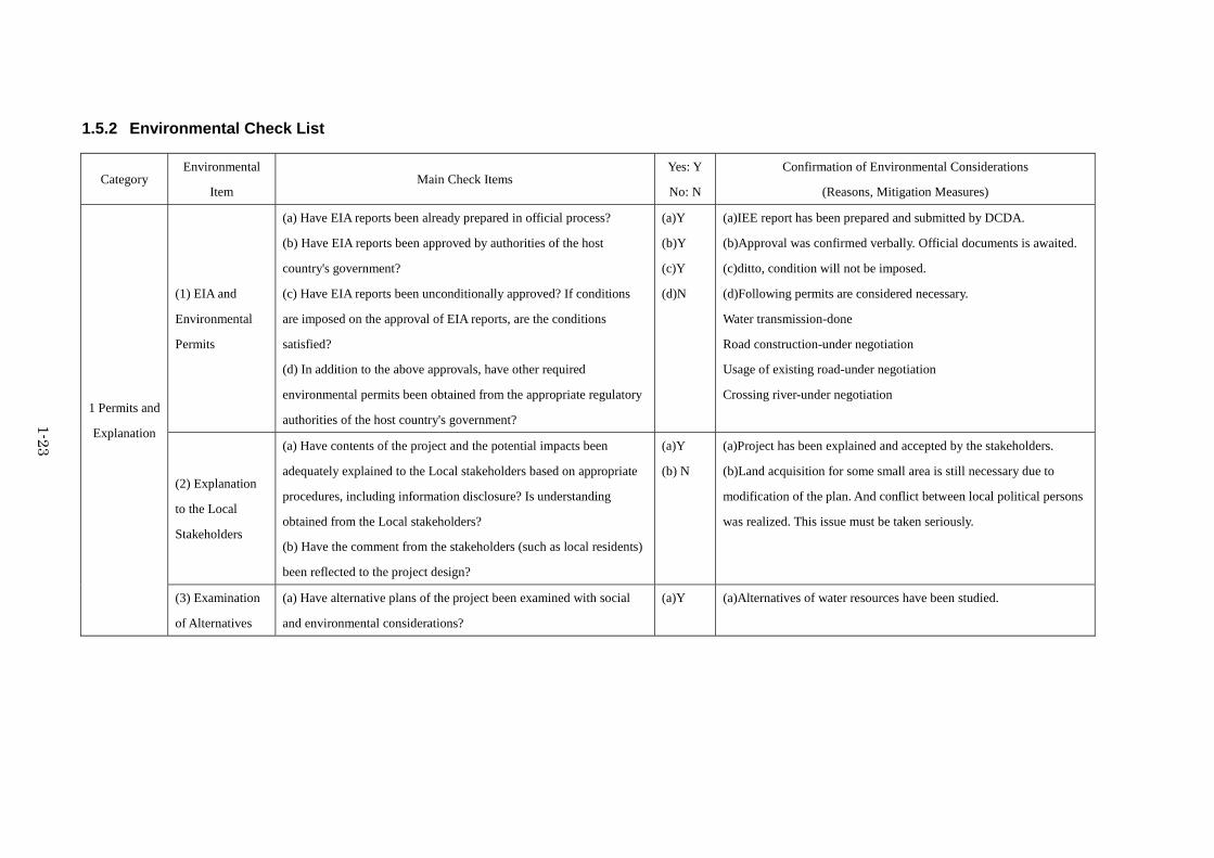
1-23
Environmental Check List 1.5.2
Category Environmental
Item Main Check Items
Yes: Y
No: N
Confirmation of Environmental Considerations
(Reasons, Mitigation Measures)
1 Permits and
Explanation
(1) EIA and
Environmental
Permits
(a) Have EIA reports been already prepared in official process?
(b) Have EIA reports been approved by authorities of the host
country's government?
(c) Have EIA reports been unconditionally approved? If conditions
are imposed on the approval of EIA reports, are the conditions
satisfied?
(d) In addition to the above approvals, have other required
environmental permits been obtained from the appropriate regulatory
authorities of the host country's government?
(a)Y
(b)Y
(c)Y
(d)N
(a)IEE report has been prepared and submitted by DCDA.
(b)Approval was confirmed verbally. Official documents is awaited.
(c)ditto, condition will not be imposed.
(d)Following permits are considered necessary.
Water transmission-done
Road construction-under negotiation
Usage of existing road-under negotiation
Crossing river-under negotiation
(2) Explanation
to the Local
Stakeholders
(a) Have contents of the project and the potential impacts been
adequately explained to the Local stakeholders based on appropriate
procedures, including information disclosure? Is understanding
obtained from the Local stakeholders?
(b) Have the comment from the stakeholders (such as local residents)
been reflected to the project design?
(a)Y
(b) N
(a)Project has been explained and accepted by the stakeholders.
(b)Land acquisition for some small area is still necessary due to
modification of the plan. And conflict between local political persons
was realized. This issue must be taken seriously.
(3) Examination
of Alternatives
(a) Have alternative plans of the project been examined with social
and environmental considerations?
(a)Y (a)Alternatives of water resources have been studied.
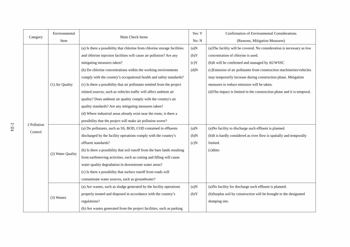
1-24
Category Environmental
Item Main Check Items
Yes: Y
No: N
Confirmation of Environmental Considerations
(Reasons, Mitigation Measures)
2 Pollution
Control
(1) Air Quality
(a) Is there a possibility that chlorine from chlorine storage facilities
and chlorine injection facilities will cause air pollution? Are any
mitigating measures taken?
(b) Do chlorine concentrations within the working environments
comply with the country’s occupational health and safety standards?
(c) Is there a possibility that air pollutants emitted from the project
related sources, such as vehicles traffic will affect ambient air
quality? Does ambient air quality comply with the country's air
quality standards? Are any mitigating measures taken?
(d) Where industrial areas already exist near the route, is there a
possibility that the project will make air pollution worse?
(a)N
(b)Y
(c)Y
(d)N
(a)The facility will be covered. No consideration is necessary as low
concentration of chlorine is used.
(b)It will be confirmed and managed by AUWSSC
(c)Emission of air pollutants from construction machineries/vehicles
may temporarily increase during construction phase. Mitigation
measures to reduce emission will be taken.
(d)The impact is limited in the construction phase and it is temporal.
(2) Water Quality
(a) Do pollutants, such as SS, BOD, COD contained in effluents
discharged by the facility operations comply with the country’s
effluent standards?
(b) Is there a possibility that soil runoff from the bare lands resulting
from earthmoving activities, such as cutting and filling will cause
water quality degradation in downstream water areas?
(c) Is there a possibility that surface runoff from roads will
contaminate water sources, such as groundwater?
(a)N
(b)N
(c)N
(a)No facility to discharge such effluent is planned.
(b)It is hardly considered as river flow is spatially and temporally
limited.
(c)ditto
(3) Wastes
(a) Are wastes, such as sludge generated by the facility operations
properly treated and disposed in accordance with the country’s
regulations?
(b) Are wastes generated from the project facilities, such as parking
(a)N
(b)Y
(a)No facility for discharge such effluent is planned.
(b)Surplus soil by construction will be brought to the designated
dumping site.

1-25
Category Environmental
Item Main Check Items
Yes: Y
No: N
Confirmation of Environmental Considerations
(Reasons, Mitigation Measures)
areas/service areas, properly treated and disposed of in accordance
with the country's regulations?
(4) Noise and
Vibration
(a) Do noise and vibrations generated from the facilities, such as
pumping stations comply with the country’s standards?
(b) Do noise and vibrations from the vehicle and train traffic comply
with the country's standards?
(a)Y
(b)Y
(a)It will be confirmed and managed by AUWSSC.
(b)It will be monitored during construction phase.
(5) Subsidence (a) In the case of extraction of a large volume of groundwater, is there
a possibility that the extraction of groundwater will cause subsidence?
(a)N (a)According to the previous study, there is no possibility of ground
subsidence. However it will be monitored.
3 Natural
Environment
(1) Protected
Areas
(a) Is the project site or discharge area located in protected areas
designated by the country’s laws or international treaties and
conventions? Is there a possibility that the project will affect the
protected areas?
(a)N (a)There is no protected area surround the project area.
3 Natural
Environment (2) Ecosystem
(a) Does the project site encompass primeval forests, tropical rain
forests, ecologically valuable habitats (e.g., coral reefs, mangroves, or
tidal flats)?
(b) Does the project site or discharge area encompass the protected
habitats of endangered species designated by the country’s laws or
international treaties and conventions?
(c) If significant ecological impacts are anticipated, are adequate
protection measures taken to reduce the impacts on the ecosystem?
(d) Is there a possibility that the amount of water used (e.g., surface
water, groundwater) by project will adversely affect aquatic
environments, such as rivers? Are adequate measures taken to reduce
(a)N
(b)N
(c)N
(d)N
(e)N
(a)There is no habitat mentioned.
(b)ditto
(c)Significant ecological impact is not foreseen.
(d)According to the previous study, it is not considered. However it
will be monitored.
(e)Small area is planned to be newly developed, However the location
is arid land and no important natural environment is recognized.

1-26
Category Environmental
Item Main Check Items
Yes: Y
No: N
Confirmation of Environmental Considerations
(Reasons, Mitigation Measures)
the impacts on aquatic environments, such as aquatic organisms?
(e) In cases the project site is located at undeveloped areas, is there a
possibility that the new development will result in extensive loss of
natural environments?
(3) Hydrology
(a) Is there a possibility that the amount of water used (e.g., surface
water, groundwater) by the project will adversely affect surface water
and groundwater flows?
(a)N (a)According to the previous study, it is not considered. However it
will be monitored.
4 Social
Environment (1) Resettlement
(a) Is involuntary resettlement caused by project implementation? If
involuntary resettlement is caused, are efforts made to minimize the
impacts caused by the resettlement?
(b) Is adequate explanation on compensation and resettlement
assistance given to affected people prior to resettlement?
(c) Is the resettlement plan, including compensation with full
replacement costs, restoration of livelihoods and living standards
developed based on socioeconomic studies on resettlement?
(d) Is the compensations going to be paid prior to the resettlement?
(e) Is the compensation policies prepared in document?
(f) Does the resettlement plan pay particular attention to vulnerable
groups or people, including women, children, the elderly, people
below the poverty line, ethnic minorities, and indigenous peoples?
(g) Are agreements with the affected people obtained prior to
resettlement?
(h) Is the organizational framework established to properly implement
(a)N
(b)Y
(c)N
(d)N
(e)N
(f)N
(g)Y
(h)Y
(i)Y
(j)Y
(a)Possibility of removal of one or two of Illegal occupation in the
ROW may be considered. However the route of water pipe can avoid
the location.
(b)In case of necessity, explanation of the project and agreement of
resettlement will be performed.
(c)Resettlement and compensation is not foreseen.
(d)ditto
(e)ditto
(f)ditto
(g)It is planned, if necessary.
(h)Certain department will be responsible.
(i)ditto
(j)ditto

1-27
Category Environmental
Item Main Check Items
Yes: Y
No: N
Confirmation of Environmental Considerations
(Reasons, Mitigation Measures)
resettlement? Are the capacity and budget secured to implement the
plan?
(i) Are any plans developed to monitor the impacts of resettlement?
(j) Is the grievance redress mechanism established?
4 Social
Environment
(2) Living and
Livelihood
(a) Is there a possibility that the project will adversely affect the
living conditions of inhabitants? Are adequate measures considered to
reduce the impacts, if necessary?
(b) Is there a possibility that the amount of water used (e.g., surface
water, groundwater) by the project will adversely affect the existing
water uses and water area uses?
(a)N
(b)N
(a)Major negative impact cannot be foreseen. Water level of the
existing wells will be monitored. With the construction, existing road
will be improved. So that positive impact is considered.
(b)According to the previous study, it is not considered. However it
will be monitored, especially the water level of existing wells.
(3) Heritage
(a) Is there a possibility that the project will damage the local
archeological, historical, cultural, and religious heritage? Are
adequate measures considered to protect these sites in accordance
(a)N (a)No local archeological, historical, cultural, and religious heritage
exists around the project area.

1-28
Category Environmental
Item Main Check Items
Yes: Y
No: N
Confirmation of Environmental Considerations
(Reasons, Mitigation Measures)
with the country’s laws?
(4) Landscape
(a) Is there a possibility that the project will adversely affect the local
landscape? Are necessary measures taken?
(a)Y (a)Elevated water pressure regulating reservoir is planned,
considering the harmonization with the tower and surrounded
landscape.
(5) Ethnic
Minorities and
Indigenous
Peoples
(a) Are considerations given to reduce impacts on the culture and
lifestyle of ethnic minorities and indigenous peoples?
(b) Are all of the rights of ethnic minorities and indigenous peoples in
relation to land and resources respected?
(a)Y
(b)Y
(a)It is considered that the affected ethnic minorities and indigenous
people do not exist.
(b)ditto
(6) Working
Conditions
(a) Is the project proponent not violating any laws and ordinances
associated with the working conditions of the country which the
project proponent should observe in the project?
(b) Are tangible safety considerations in place for individuals
involved in the project, such as the installation of safety equipment
which prevents industrial accidents, and management of hazardous
materials?
(c) Are intangible measures being planned and implemented for
individuals involved in the project, such as the establishment of a
safety and health program, and safety training (including traffic safety
and public health) for workers etc.?
(d) Are appropriate measures taken to ensure that security guards
involved in the project not to violate safety of other individuals
involved, or local residents?
(a)Y
(b)Y
(c)Y
(d)Y
(a)This will be considered in the Environmental Management Plan.
(b)ditto
(c)ditto
(d)ditto
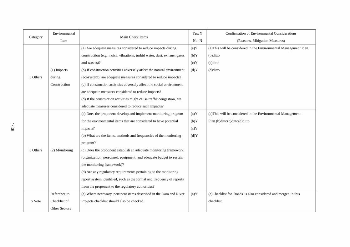
1-29
Category Environmental
Item Main Check Items
Yes: Y
No: N
Confirmation of Environmental Considerations
(Reasons, Mitigation Measures)
5 Others
(1) Impacts
during
Construction
(a) Are adequate measures considered to reduce impacts during
construction (e.g., noise, vibrations, turbid water, dust, exhaust gases,
and wastes)?
(b) If construction activities adversely affect the natural environment
(ecosystem), are adequate measures considered to reduce impacts?
(c) If construction activities adversely affect the social environment,
are adequate measures considered to reduce impacts?
(d) If the construction activities might cause traffic congestion, are
adequate measures considered to reduce such impacts?
(a)Y
(b)Y
(c)Y
(d)Y
(a)This will be considered in the Environmental Management Plan.
(b)ditto
(c)ditto
(d)ditto
5 Others (2) Monitoring
(a) Does the proponent develop and implement monitoring program
for the environmental items that are considered to have potential
impacts?
(b) What are the items, methods and frequencies of the monitoring
program?
(c) Does the proponent establish an adequate monitoring framework
(organization, personnel, equipment, and adequate budget to sustain
the monitoring framework)?
(d) Are any regulatory requirements pertaining to the monitoring
report system identified, such as the format and frequency of reports
from the proponent to the regulatory authorities?
(a)Y
(b)Y
(c)Y
(d)Y
(a)This will be considered in the Environmental Management
Plan.(b)ditto(c)ditto(d)ditto
6 Note
Reference to
Checklist of
Other Sectors
(a) Where necessary, pertinent items described in the Dam and River
Projects checklist should also be checked.
(a)Y (a)Checklist for 'Roads' is also considered and merged in this
checklist.

1-30
Category Environmental
Item Main Check Items
Yes: Y
No: N
Confirmation of Environmental Considerations
(Reasons, Mitigation Measures)
Note on Using
Environmental
Checklist
(a) If necessary, the impacts to trans-boundary or global issues should
be confirmed (e.g., the project includes factors that may cause
problems, such as trans-boundary waste treatment, acid rain,
destruction of the ozone layer, or global warming).
(a)N (a)No such impact is foreseen.
1) Regarding the term “Country’s Standards” mentioned in the above table, in the event that environmental standards in the country where the project is located diverge significantly from international standards,
appropriate environmental considerations are required to be made.
In cases where local environmental regulations are yet to be established in some areas, considerations should be made based on comparisons with appropriate standards of other countries (including Japan's experience).
2) Environmental checklist provides general environmental items to be checked. It may be necessary to add or delete an item taking into account the characteristics of the project and the particular circumstances of the
country and locality in which the project is located.

2-1
Concepts of the Project Chapter 2
2.1. Basic Concept of the Project
Overall Goal and Project Purpose 2.1.1
The Government of Afghanistan plans to develop the New City, which locates in the north east area of Kabul City, in order to settle the exponential growth of population and the deficiency of residential property for the Kabul metropolitan area. The water supply facilities are planned in the first phase development area (Parcel-1, Development area: approximately 830 ha, Design population: 42,000) by 2015. However, there are neither the existing water supply facilities nor sufficient water resources which sustain the Parcel-1 area. Therefore, it is necessary to transmit the water from water resource outside of Parcel-1. Under such circumstances, the project objectives are to develop water resource, to construct intake and water transmission facilities and principal water distribution lines, and to secure the required water in the Parcel-1.
Basic Concept of the Project 2.1.2
Two (2) production wells, a reservoir, a water transmission pumping station, a water transmission main, a water pressure regulating reservoir and principal water distribution lines will be constructed under this Project. Accordingly, the Project contributes to secure 119 LCD (Liter/capita/day) as the per capita daily maximum water supply for Parcel-1 in 2015. The scope of Japanese assistance is construction of facilities consisting of production wells, a reservoir for wells, a water transmission pumping station, a water transmission main, a water pressure regulating reservoir and principal water distribution lines.
2.2. Outline Design of the Japanese Assistance
Design Policy 2.2.1
Basic Concept 2-2-1-1The scope of Japanese assistance aims to transmit the required water to Parcel-1. Moreover, the
water sources of 5,000m3/day as the daily maximum pump discharge is secured in Pol-e Charkhi area. According to these conditions, the following illustrates the basic concept of the Project.
Target Area of the Japanese Assistance (1)The target area of the Japanese assistance is Parcel-1. The project sites include Pol-e Charkhi area
(the production wells, the reservoir for wells and the water transmission pumping station), adjacent to the land locating near the Parcel-1 (the water pressure regulating reservoir), the existing roads for water conveyance and transmission lines and the construction site of Parcel-1.
Design Service Population for Water Supply (2)The design service population for water supply is 42,000 in the target year of 2015 in accordance
with the development plan of DCDA.

2-2
Design Water Supply (3)The basis of the design water supply for the facilities planning is 150 LCD which is the design
water supply per capita per day in MP. It is equivalent to 8,190m3/day as the design daily maximum water supply. However, the maximum daily extracting volume of 5,000m3/day is applicable for the design of intake and water distribution facilities. It is equivalent to 119 LCD. The extra water volume, which cannot be covered by this grant aid project, will be separately secured by DCDA.
Component of the Japanese Assistance (4)The component of Japanese assistance covers intake facility, reservoir, water transmission pump
facilities, water transmission mains, water pressure regulating reservoir and principal water distribution lines. DCDA will urge private developers in Percel-1 to cooperate construction of other distribution main and branch pipelines (approximately 17.2 km) required for water distribution from the water pressure regulating reservoir. Water distribution branches laying in the town and housing areas will be constructed with the budget of private developers.
Concept Regarding Natural Conditions 2-2-1-2Frequent earthquakes hit Afghanistan and earthquake resistant structure should be applied in the
design. Moreover, it snows and becomes freezing temperature in winter. Snow loads and cryogenic temperatures shall be taken account in the design.
Concept Regarding Social and Economic Conditions 2-2-1-3Anti-governmental activities have been still active in Afghanistan. Therefore, the exposed pipes,
which may become potential target of attacks, should be refrained as much as possible or paved with concreted if exposure on the ground is unavoidable. Moreover, the properties such as a pumping station and reservoirs should be surrounded with concrete structures. Therefore, Japan’s assistance will include construction of these facilities.
Those areas, where pressure regulating reservoir will be constructed, have not been electrified. Therefore, use of electricity in the structures and facility operation should be prevented. Yet, the design of these facilities shall allow installing electrical equipment and instruments in the future.
Concept Regarding Construction and Procurement Conditions 2-2-1-4A number of construction and development projects have been undertaken by assistance of donors
such as the United Nations. Capacity of construction companies has been improved and the markets for construction materials have been matured. Therefore, it can be concluded that no special consideration is required for procurement of general construction materials and contractors for construction of facilities.
Among the required construction materials in this Project, pipes and concrete materials can be procured in the local markets. On the other hand, majority of electrical and mechanical facilities including pumping devices should be imported or procured among imported items. Therefore, both local and international markets should be considered for the construction and procurement plans.
There are several metal and steel processing factories. Therefore, procurement of processed steel is available. On the other hand, there is no factory available which markets secondary products such as steel tanks based on sufficient experience and sales record. Therefore, the structure of water tanks shall

2-3
be limited to the reinforced concrete types.
Concept Regarding Utilization of Local Contractors 2-2-1-5Local construction companies and vendors are available in local markets. Therefore, capacity and
capability of local contractors should be taken account in design and specification.
Concept Regarding Operation and Maintenance 2-2-1-6DCDA and AUWSSC have agreed that AUWSSC will be responsible for operation and
maintenance of water supply and sewerage services of the New City. DCDA will lead facility construction. The facilities will be transferred to AUWSSC and AUWSSC will conduct operation of water supply and sewerage services.
AUWSSC has faced severe conditions in the aspects of operation, maintenance and finance. Additionally, securing appropriate engineers and skilled labors is one of the issues due to high rate of leaving their jobs. Therefore, simple structure of facilities in terms of operation and maintenance should be adopted. Especially it is important to minimize the electrical and electrical signal type operation systems in consideration of troubles.
Concept Regarding Grade of Facility and Materials 2-2-1-7The facilities in this Project consist of ordinal structures such as concrete structures, pipelines for
water supply, pump facilities including wells and transmission of water. Therefore, special attention on selection of grade of facilities and materials is not required.
Concept Regarding Construction and Procurement Plans, and Schedule 2-2-1-8It is assumed the United Nations Office for Project Services (hereinafter referred to as “UNOPS”)
will stand as a procurement agency on behalf of the Government of Afghanistan. Therefore, procurement plans shall take account of the procurement scheme of the UNOPS.
A part of main pipelines will be developed under the pilot project of the Infrastructure SP. It is important the construction schedule should be harmonized with the pilot project.
Basic Plan (Construction Plan / Equipment Plan) 2.2.2
Overall Plan 2-2-2-1This Project covers production wells, a reservoir, a water transmission pump facility, a water
transmission main, a water pressure regulating reservoir and principal water distribution lines. For the purpose to secure necessary water head for water supply, elevated tank is applied as water pressure regulating reservoir. It is difficult to construct large scale elevated tanks due to structure and issues relating to land acquisition. Water reservoir and water transmission pump facility shall be constructed near production wells in respect to cost reduction. Therefore, the water reservoir can be utilized for distribution to Kabul city in the future. Figure 2-1 and Table 2.1 shows the outlines of each facility.

2-4
Figure 2-1 Outline of the Project
Table 2.1 Scope of Japanese Assistance Facility Name Components Specifications
1. Pol-e Charihi Well Station (1) Production well (PW-1, PW-2)
Deep well, Submersible pump, Power receiving equipment
Production well: 2 units (One (1) well is the existing test well) Pump Capacity; 2,500 m3/day x 2 units Pumping Head: 23 m. Necessary electrical facilities.
(2) Water Conveyance Pipeline
Water conveyance facility L = 1.6 km, Outer Diameter: 250 mm and 180 mm, HDPE
(3) Reservoir and Water Transmission Pimp Facility
Reservoir (R-Well) 1 location, 1,700 m3 (850 m3 x 2 units), Reinforced concrete
Water transmission pump, Power receiving equipment
Pump capacity: 1.7 m3/min x 3 units and 1 unit for standby, Pump head: 90m, necessary electrical facilities.
Disinfection facility Calcium Hypochlorite Solution Tank, Calcium Hypochlorite Dosing Pump, necessary electrical facilities.
(4) Monitoring Wells Deep well Monitoring wells: 4 units (5) Maintenance facilities Operation room at Pol-e
Charihi Well Station Guardhouse, Flow meter, water quality analytical equipment, Tools for maintenance
2. Pipeline Transmission and distribution lines
L = 36.5 km, Outer diameter: 125 ~ 500 mm, HDPE
3. Water pressure regulating reservoir
Elevated tank (R-P1) 1 location, 400 m3 (400 m3 x 1 unit), Reinforced concrete
Design Conditions 2-2-2-2 Design Water Quality (1)There is no specific drinking water quality standard in Afghanistan and the standard of World
Health Organization (WHO) is commonly applied. This Project also adopts the WHO’s drinking water standard in design. A water quality examination for the test wells was conducted under the Sub-Project
Water pressure regulating reservoir (R-P1)
Water Transmission main L=18.1km
Reservoir & transmission pump facility Production Well No.1 (PW-1)
Production Well No.2 (PW-2) Water conveyance pipelines
Principal Water Distribution Lines
Parcel-1

2-5
for Groundwater Survey for Dehsabz South Development Area (hereinafter referred to as Groundwater SP). The result of the test concluded the groundwater is suitable as water resources of drinking water (results of the test are shown in Table 2.2 and Table 2.3)
Table 2.2 Result of Water Quality Analysis Parameter Unit TW-1 TW-2 WHO’s Guidelines (4th edition)
Water Temperature ℃ 25.0 20.8 -
pH - 7.7 7.6 6.5-8.5
Electrical Conductivity (EC) μS/cm at 25℃ 800 950 -
DO mg/l 6.2 4.8 -
COD mg/l 2 2 -
BOD mg/l 2 2 -
Anionic Surfactant mg/l 0.05 0.10 < 0.2 mg/l ( Drinking water quality standard)
Coliforms CFU/ml 15 0 Not detected ( Drinking water quality standard)by EC-plate
CFU/ml 26 0 Not detected ( Drinking water quality standard)by Coliform detection paper
Fecal Coliform (E. Coli) CFU/ml 0 0 Not detected ( Drinking water quality standard)
Standard Plate Count Bacteria CFU/ml 14 120 -
Turbidity NTU 0.5 0.5 < 5 NTU
Alkalinity mg/l as CaCO3
210 320 -
Bicarbonate (HCO3-) mg/l 256 390 -
Ammonia (NH3) mg/l as NH3-N 0.05 0.03 -
Nitrite (NO2-) mg/l as
NO2-N 0.003 0.004 < 3mg/l(short‐term exposure)
Nitrate (NO3-) mg/l as
NO3-N 7.0 8.1 < 50 mg/l(short‐term exposure)
Hardness mg/l as CaCO3
450 480 -
Sodium (Na+) mg/l 75 62 < 50 mg/l
Potassium (K+) mg/l 3.5 1.5 -
Magnesium (Mn2+) mg/l as CaCO3
285 295 -
Calcium (Ca2+) mg/l as CaCO3
165 185 -
Iron, Total (T-Fe) mg/l 0.02 0.02 < 0.3 mg/l
Manganese (Mn2+) mg/l 0.2 1.1 < 0.4 mg/l
Chloride (Cl-) mg/l 87.5 62.5 < 250 mg/l
Sulfate (SO42-) mg/l 140 160 < 500 mg/l
Fluoride (F-) mg/l 0.34 0.40 < 1.5 mg/l
Arsenic (As) mg/l 0.000 0.000 < 0.01 mg/l
Source: Water quality examination in the Groundwater SP

2-6
Table 2.3 Result of Heavy Metal Analysis Parameter Unit TW-1 TW-2 WHO’s guidelines (4th edition)
Cadmium mg/l <0.001 <0.001 < 0.003 mg/l
Cyan, Total mg/l Not detected < 0.0006 mg/l
Lead mg/l <0.005 <0.005 < 0.01 mg/l
Chromium (VI) mg/l <0.01 <0.01 < 0.05 mg/l
Arsenic mg/l <0.005 <0.005 < 0.01 mg/l
Mercury, Total mg/l <0.0005 <0.0005 < 0.006 mg/l
Selenium mg/l <0.002 <0.002 < 0.04 mg/l
Fluoride mg/l 0.40 0.38 < 1.5 mg/l
Boron mg/l 0.15 0.15 < 2.4 mg/l
Source: Water quality examination in the Groundwater SP
Design Condition 2-2-2-3Design conditions to be applied are defined in Table 2.4.
Table 2.4 Design Condition Parameters Quantity Unit Applicable Facility
Design water supply per capita 150 LCD a. Design service population 42,000 Persons b. Design maximum daily extracting volume 5,000 m3/day Volume of distribution reservoir c. =d x 2
Design maximum daily extracting volume 2,500 m3/day Per well d.
Design maximum daily extracting volume 1.8 m3/min Diameter of pipes and specification
of pumps of production wells e. =d
Daily variation coefficient *1 1.3 - f. Design load *1 0.769 g = 1/f Hourly variation coefficient *2 1.4 - H Design maximum daily water supply volume 8,190 m3/day Water pressure regulating reservoir i.=a x b x f
Design maximum hourly water transmission volume 1.7 m3/min Water transmission pumps (per
pump) j. =c x h / 3
Design maximum hourly water transmission volume 5.1 m3/min Diameter of transmission pipelines
(during operation of 3 pumps) k. =j x3
Design maximum hourly water distribution volume 11,466 m3/day Diameter of distribution pipeline l. =i x h
*1 Based on the master plan. Daily variation coefficient of 1.3 is equivalent to design load of 0.769 (reciprocal). In
accordance with the guidelines for water facility design (Japan Water Works Association), design load is commonly applied
for design of water facilities. However, based on the results of discussion between the team and DCDA, daily variation
coefficient will be applied for design for avoiding confusion in terminology.
*2 Hourly variation coefficient was calculated based on Japan’s design criteria for waterworks facilities.
Hourly variation coefficient (K) = 2.7445 x (Q/24)-0.0726 where; Q: Daily maximum water supply (m3/day) The expected design population in 2025 is 1.5 million based on the master plan.
Q = 150LCD x 1.3 x 1.5 x 106 = 292,500 m3/day Therefore, 1.4 was adopted as hourly variation coefficient
K=2.7445 x (292,500/24)-0.0726=1.386 ≒1.4

2-7
Seismic Load (1)No clear standard for seismic load has been established in Afghanistan. Yet, design horizontal
seismic coefficient of Kh = 0.3 or equivalent is commonly applied for important structures. In this Project, Kh = 0.3 is applicable for design since the value is equivalent to Japanese architectural standard.
C≧0.3 Zs I where, Zs : 1.0 is applied as regional seismic coefficient I : 1.0 is applied as usage coefficient. Since water tanks and control building are integrated
as one function, 1.0 is applied for the whole system. (Source: Design recommendation for storage tanks and their supports, Architectural Institute of Japan)
Wind Load (2)Wind load is considered for those structures which are potentially influenced by wind such as the
water pressure regulating reservoir. No clear standard on wind load has been established in Afghanistan, but the load can be calculated based on the Japanese relevant criteria.
P=Q・C・A where; P : Wind Load (kN) Q : Wind Pressure KN/m2 C : Wind Coefficient 0.7 A : Effective projection area (m2)
Snow Load (3)No clear criteria on snow load are established in Afghanistan. However, snowfall is foreseen during
winter period and load of snow shall be included in the design. S=Ws×Zs× b
where; S: Snow Load (kN) = 1 KN/ m2 Ws : Average unit weight of snow (at heavy snow region) 20 N/m2/cm Zs : Design snow depth 50cm μb : Roof shape coefficient due to slope 1.0 (no slope)
Facility Layout Plan 2.2.3
Pol-e Charikhi Well Station (1)(a) Layout of Pol-e Charikhi Well Station
DCDA prepare the plan of layout of Pol-e Charikhi Well Station as Figure 2-2. The existing test wells will be used as production wells and water transmission facilities will be constructed adjacent to the production wells.

2-8
Figure 2-2 Layout of Pol-e Charikhi Well Station
(b) Structure of Pol-e Charikhi Well Station The main structures of the Pol-e Charikhi Well Station are shown below and Figure 2-3 shows the
overall system of the station. Production Wells (+ Well Pumps): 2 Wells (PW-1, PW-2) Water Distribution Conveyance lines:PW-1 ~ R-Well, PW-2 ~ R-Well Water Reservoir(R-Well) Water Transmission Pump Facility Control Building Monitoring Wells:4 Wells
Figure 2-3 Pol-e Charikhi Well Station System
: Calcium hypochlorite dosing pipe
PP
PTo R-P1
R-well
Controlbuilding
Production well No.2
Production well No.1
P
P : Submergible pump
: Water transmission pump
: Water conveyance pipe
: Water Transmission main
P
Calcium hypochlorite solution tank
M
M
: Ultrasonic flow meterM
: Calcium hypochlorite dosing pump
M
P
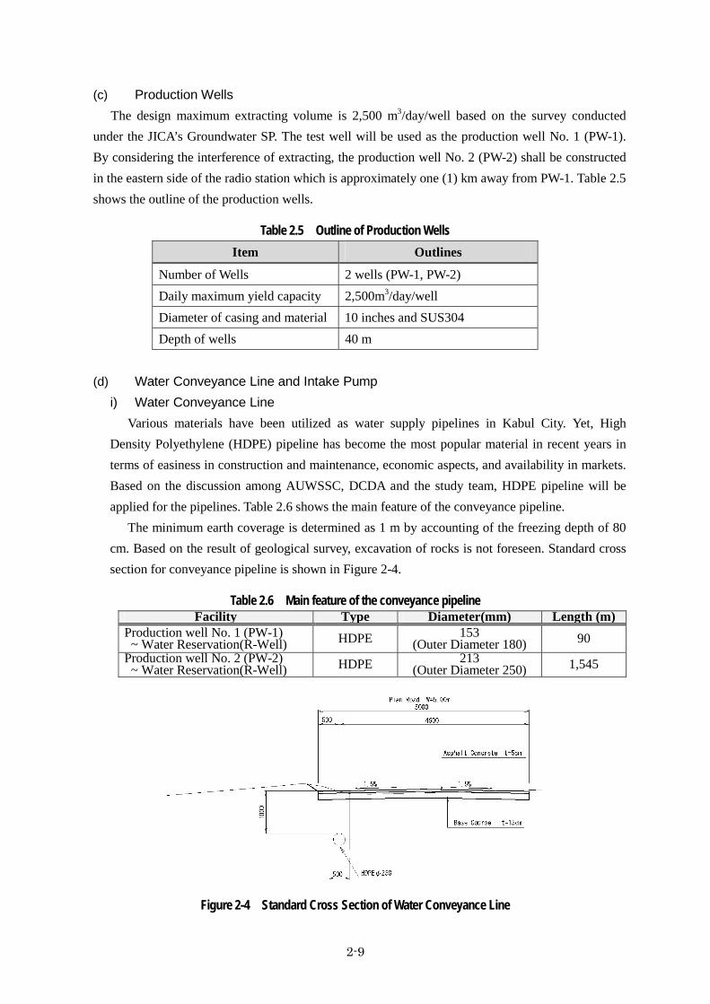
2-9
(c) Production Wells The design maximum extracting volume is 2,500 m3/day/well based on the survey conducted
under the JICA’s Groundwater SP. The test well will be used as the production well No. 1 (PW-1). By considering the interference of extracting, the production well No. 2 (PW-2) shall be constructed in the eastern side of the radio station which is approximately one (1) km away from PW-1. Table 2.5 shows the outline of the production wells.
Table 2.5 Outline of Production Wells Item Outlines
Number of Wells 2 wells (PW-1, PW-2) Daily maximum yield capacity 2,500m3/day/well Diameter of casing and material 10 inches and SUS304 Depth of wells 40 m
(d) Water Conveyance Line and Intake Pump
i) Water Conveyance Line Various materials have been utilized as water supply pipelines in Kabul City. Yet, High
Density Polyethylene (HDPE) pipeline has become the most popular material in recent years in terms of easiness in construction and maintenance, economic aspects, and availability in markets. Based on the discussion among AUWSSC, DCDA and the study team, HDPE pipeline will be applied for the pipelines. Table 2.6 shows the main feature of the conveyance pipeline.
The minimum earth coverage is determined as 1 m by accounting of the freezing depth of 80 cm. Based on the result of geological survey, excavation of rocks is not foreseen. Standard cross section for conveyance pipeline is shown in Figure 2-4.
Table 2.6 Main feature of the conveyance pipeline Facility Type Diameter(mm) Length (m)
Production well No. 1 (PW-1) ~ Water Reservation(R-Well) HDPE 153
(Outer Diameter 180) 90 Production well No. 2 (PW-2) ~ Water Reservation(R-Well) HDPE 213
(Outer Diameter 250) 1,545
Figure 2-4 Standard Cross Section of Water Conveyance Line
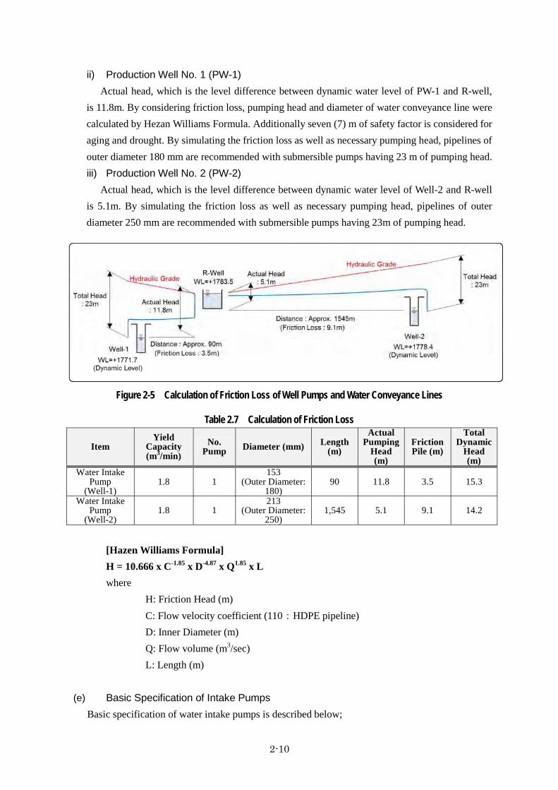
2-10
ii) Production Well No. 1 (PW-1) Actual head, which is the level difference between dynamic water level of PW-1 and R-well,
is 11.8m. By considering friction loss, pumping head and diameter of water conveyance line were calculated by Hezan Williams Formula. Additionally seven (7) m of safety factor is considered for aging and drought. By simulating the friction loss as well as necessary pumping head, pipelines of outer diameter 180 mm are recommended with submersible pumps having 23 m of pumping head. iii) Production Well No. 2 (PW-2)
Actual head, which is the level difference between dynamic water level of Well-2 and R-well is 5.1m. By simulating the friction loss as well as necessary pumping head, pipelines of outer diameter 250 mm are recommended with submersible pumps having 23m of pumping head.
Figure 2-5 Calculation of Friction Loss of Well Pumps and Water Conveyance Lines
Table 2.7 Calculation of Friction Loss
Item Yield
Capacity (m3/min)
No. Pump Diameter (mm) Length
(m)
Actual Pumping
Head (m)
Friction Pile (m)
Total Dynamic
Head (m)
Water Intake Pump
(Well-1) 1.8 1
153(Outer Diameter:
180)90 11.8 3.5 15.3
Water Intake Pump
(Well-2) 1.8 1
213(Outer Diameter:
250)1,545 5.1 9.1 14.2
[Hazen Williams Formula] H = 10.666 x C-1.85 x D-4.87 x Q1.85 x L where
H: Friction Head (m) C: Flow velocity coefficient (110:HDPE pipeline) D: Inner Diameter (m) Q: Flow volume (m3/sec) L: Length (m)
(e) Basic Specification of Intake Pumps Basic specification of water intake pumps is described below;

2-11
i) Production Pump No. 1 (Well-1) Type : Deep well submergible pump Quantity : 1 unit Unit capacity : 1.8 m3/sec Total dynamic head : 23 m Motor : Submergible motor
Electricity : 400V x 50 Hz Motor Output : Approximately 15 kW
ii) Production Pump No. 2 (Well-2) Type : Deep well submergible pump Quantity : 1 unit Unit capacity : 1.8 m3/sec Total dynamic head : 23 m Motor : Submergible motor
Electricity : 400V x 50 Hz Motor Output : Approximately 15 kW
(f) Water Reservoir: R-well
i) Capacity The capacity is to be 8 hours capacity of the daily maximum yield volume of 5,000 m3/day.
Therefore, it was calculated at 1,700 m3. Volume V (m3) = 5,000m3/day / 24hour x 8hour = 1,666 m3 (≒1,700m3)
ii) Number of Tanks By considering maintenance aspects, two (2) units shall be designed. Therefore, the unit
capacity of the reservoir is 850 m3. iii) Structure
Reinforced concrete structure will be adopted. (g) Structure of Control Building
The control building consists of chemical room, electricity room, pump room and administration room. Reinforced concrete structure will be adopted. As an anti frost measure, thermal insulating material will be used in walls for chemical room, pump room and administration room (except electricity room). (h) Transmission Pump Facility
i) Hydrologic Accounting Actual head, which is the level difference between R-well and R-P1, is 60.1m. Considering
friction loss, pumping head and diameter of water distribution line were calculated by Hezan Williams Formula. By simulating the friction loss as well as necessary pumping head, pipeline of outer diameter 500 mm is recommended with pumps having 90 m of pumping head. Simulation
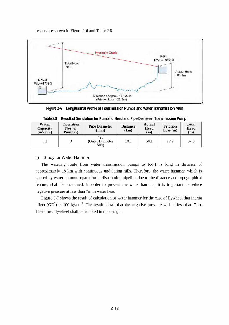
2-12
results are shown in Figure 2-6 and Table 2.8.
Figure 2-6 Longitudinal Profile of Transmission Pumps and Water Transmission Main
Table 2.8 Result of Simulation for Pumping Head and Pipe Diameter: Transmission Pump Water
Capacity (m3/min)
Operation Nos. of
Pump (-) Pipe Diameter
(mm) Distance
(km) Actual Head (m)
Friction Loss (m)
Total Head (m)
5.1 3 426
(Outer Diameter 500)
18.1 60.1 27.2 87.3
ii) Study for Water Hammer The watering route from water transmission pumps to R-P1 is long in distance of
approximately 18 km with continuous undulating hills. Therefore, the water hammer, which is caused by water column separation in distribution pipeline due to the distance and topographical feature, shall be examined. In order to prevent the water hammer, it is important to reduce negative pressure at less than 7m in water head.
Figure 2-7 shows the result of calculation of water hammer for the case of flywheel that inertia effect (GD2) is 100 kg/cm2. The result shows that the negative pressure will be less than 7 m. Therefore, flywheel shall be adopted in the design.

2-13
Figure 2-7 Negative Pressure on Water Transmission Main
(i) Basic Specification of Water Transmission Pump Basic specification of water transmission pump and motor unit is as follows; i) Water Transmission Pump
Type : horizontal shaft, multistage centrifugal pump Quantity : 4 units (1 unit is for standby) Unit capacity : 1.7 m3/sec Total dynamic head : 90 m Pump rated efficiency : Not less than 65.0%
ii) Motor for Water Transmission Pump Type : Squirrel cage induction motor Quantity : 4 units Motor output : Approx. 45 kW Maximum ambient temperature : 50 degree C Electrical supply : AC 400V x 50 Hz
(j) Disinfection Facility
According to confirmation with AUWSSC, 30% concentration of calcium hypochlorite (bleaching powder) is usually utilized by AUWSSC. It is difficult in Afghanistan to procure high concentration hypochlorite or sodium hypochlorite solution. Therefore, solid status calcium hypochlorite (30% of concentration) will be dissolved into water and injected at the entrance of the reservoir.
Assuming the dosing rate at minimum 0.5mg/l and maximum 3mg/l, the following equipment is recommended:

2-14
i) Calcium Hypochlorite Solution Tank Type : Cylindrical tank, open top type Quantity : 2 units Capacity : 1,000 L
ii) Calcium Hypochlorite Dosing Pump Type : Metering Pump Quantity : 2 units Unit capacity : 360 mL/min Discharge Pressure : Approx. 1 MPa Electricity : 230V x 50 Hz Output : Approx. 30 W
(k) Flow Meter
Two (2) units of ultrasonic flow meters will be installed to manage the extracted volume from each production wells. In the similar manner, one (1) unit of ultrasonic flow meter will be installed at the transmission pump facility. (l) Monitoring Wells
Four (4) monitoring wells will be provided nearby the production wells for monitoring the groundwater level and water quality. Table 2.9 shows the outline of the monitoring wells.
Table 2.9 Outline of Monitoring Wells Item Outlines
Number of Wells 4 wells Diameter of casing and material 4 inches and PVC Depth of wells 40 m
Power Receiving and Control System (2)The condition of electricity power supply is in general recognized as poor. Variation in frequency
and voltage in the supplied electricity is considerably large and blackout frequently occurs in Afghanistan. The electricity power supply source for this Project is from the Pol-e Charikhi substation with a dedicated line. Hence, stabilized power supply is expected and emergency generators are not required for the Project.
(a) Required Electrical Energy Required electrical power for the pump operation at each well is summarized in Table 2.10.
Table 2.10 Necessary Electric Power for Pump No. Facility Necessary Power (kW)
1 No.1 Production Well (Well-1) 220
2 No.2 Production Well (Well-2) 20
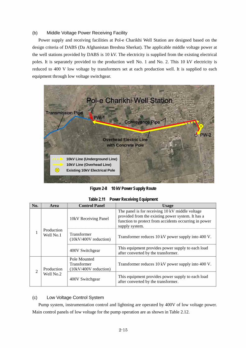
2-15
(b) Middle Voltage Power Receiving Facility Power supply and receiving facilities at Pol-e Charikhi Well Station are designed based on the
design criteria of DABS (Da Afghanistan Breshna Sherkat). The applicable middle voltage power at the well stations provided by DABS is 10 kV. The electricity is supplied from the existing electrical poles. It is separately provided to the production well No. 1 and No. 2. This 10 kV electricity is reduced to 400 V low voltage by transformers set at each production well. It is supplied to each equipment through low voltage switchgear.
Figure 2-8 10 kV Power Supply Route
Table 2.11 Power Receiving Equipment No. Area Control Panel Usage
1 Production Well No.1
10kV Receiving Panel
The panel is for receiving 10 kV middle voltage provided from the existing power system. It has a function to protect from accidents occurring in power supply system.
Transformer (10kV/400V reduction) Transformer reduces 10 kV power supply into 400 V.
400V Switchgear This equipment provides power supply to each load after converted by the transformer.
2 Production Well No.2
Pole Mounted Transformer (10kV/400V reduction)
Transformer reduces 10 kV power supply into 400 V.
400V Switchgear This equipment provides power supply to each load after converted by the transformer.
(c) Low Voltage Control System Pump system, instrumentation control and lightning are operated by 400V of low voltage power.
Main control panels of low voltage for the pump operation are as shown in Table 2.12.
10kV Line (Overhead Line) Existing 10kV Electrical Pole
10kV Line (Underground Line)
Overhead Electric Linewith Concrete Pole

2-16
Table 2.12 Main Control Panels in Pump House No. Item Description
1 Power Distribution Panel
Power distribution panel is a device to distribute 400 V of low voltage electrical power to major electrical equipment, such as pump, motorized valve, etc, on pump operation.
2 Well Pump Local Control Panel
Well pump local control panel is a device to conduct field control of well pump system. This panel is installed beside each well.
3 Chemical Panel Chemical panel is a device to operate the calcium hypochlorite dosing system.
4 Monitoring and Control Panel
Monitoring & control panel is a device to operate pump system and to monitor the operation condition. In case trouble is detected, alarm will beep to notify the mal condition.
5 Aux. Relay Panel Aux. relay panel is a device to interface a signal on controlling the pump system.
6 Lightning Panel Lightning panel is a device to supply the electrical power for the lightning and other general services.
(d) Operation of Well Pump System
Operation of well pumps can be conducted by two (2) modes, “Auto” and “Manual”. By connecting the control cable between wells and water reservoir (R-Well), automatic operation system will be introduced by reflecting water level at the water reservoir (R-Well). Manual operation mode is also available for inspection, repair and emergency cases. Interlock condition on automatic and manual operations and operational concept are as illustrated in Figure 2-9.
i) Interlock Condition at Automatic Operation Mode a) In case that a well water level becomes low by aging or drought, well pump stops
automatically to prevent dry operation. b) In case that a water level becomes middle water level in R-well, well pump operates
automatically. c) In case that a water level reaches high water level in R-well, pump stops automatically.
ii) Interlock Condition at Manual Operation Mode For case of emergency or any trouble of automatic system, the well pump is controllable to
switch on / off in manual.
Figure 2-9 Operation Concept on Well Pump Control

2-17
Operation of Water Transmission Pump System (3)Electricity power supply has not been served in the area where water pressure regulating reservoir
is constructed. Therefore, On/Off control of water transmission pump is done manually. However, in order to prevent the overflow from R-P1 by the human error, float valve is installed at inlet pipe of R-P1 for compulsive shut down of the water transmission if water level raises at a certain height. In case that an inner pressure of pipeline rises by closing action of float valve, pressure switch detect the high pressure and triggers emergency stop of pump operation. Interlock condition in the operation is as follows, and operational concept is as shown in Figure 2-10.
(a) Basic Operation Procedure Water level will be observed by visual inspection at the water pressure regulating reservoir
(R-P1) and the information of the water level (low / middle / high) will be transmitted to the operator by telephone.
Operator controls the transmission pump based on the water level information at the water pressure regulating reservoir (R-P1).
The best suitable operation mode will be prepared during the trial operation and efficient and systematic operation mode will be established.
(b) Interlock Condition for Manual Operation
a) In case that a water level in R-well is under the low level, pump does not start the operation even the start button is pressed in manual.
b) In case that a water level becomes lower alarm level (LWL) in R-well, pump stops immediately to prevent dry operation.
c) The air would be mixed into the pump due to lower level of R-well, which is lower than the lower low level. It may be caused by malfunctions of water level meter in R-well. In this case, water transmission pressure will decrease in the transmission main due to the mixed air. For such case, the pressure switch assembled in transmission pipe detects the low pressure, and then the pumps stop immediately to prevent dry operation.
d) In case that the pressure switch detects high pressure in the water transmission main, pumps stop automatically.
Figure 2-10 Operation Concept on Water Transmission Pump Control
▽LLWL : Emergency Stop P
▽LWL : ALARM LEVELPS
Water Pressure Regulating Reservoir
(R-P1)
Reservoir (R-Well)Pol-e Charikhi Well Station
Overflow/ Drain
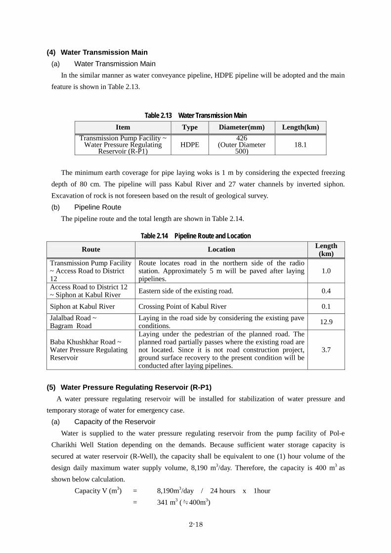
2-18
Water Transmission Main (4)(a) Water Transmission Main
In the similar manner as water conveyance pipeline, HDPE pipeline will be adopted and the main feature is shown in Table 2.13.
Table 2.13 Water Transmission Main Item Type Diameter(mm) Length(km)
Transmission Pump Facility ~ Water Pressure Regulating
Reservoir (R-P1) HDPE
426(Outer Diameter
500)18.1
The minimum earth coverage for pipe laying woks is 1 m by considering the expected freezing
depth of 80 cm. The pipeline will pass Kabul River and 27 water channels by inverted siphon. Excavation of rock is not foreseen based on the result of geological survey. (b) Pipeline Route
The pipeline route and the total length are shown in Table 2.14.
Table 2.14 Pipeline Route and Location
Route Location Length(km)
Transmission Pump Facility ~ Access Road to District 12
Route locates road in the northern side of the radio station. Approximately 5 m will be paved after laying pipelines.
1.0
Access Road to District 12 ~ Siphon at Kabul River Eastern side of the existing road. 0.4
Siphon at Kabul River Crossing Point of Kabul River 0.1 Jalalbad Road ~ Bagram Road
Laying in the road side by considering the existing pave conditions. 12.9
Baba Khushkhar Road ~ Water Pressure Regulating Reservoir
Laying under the pedestrian of the planned road. The planned road partially passes where the existing road are not located. Since it is not road construction project, ground surface recovery to the present condition will be conducted after laying pipelines.
3.7
Water Pressure Regulating Reservoir (R-P1) (5)A water pressure regulating reservoir will be installed for stabilization of water pressure and
temporary storage of water for emergency case. (a) Capacity of the Reservoir
Water is supplied to the water pressure regulating reservoir from the pump facility of Pol-e Charikhi Well Station depending on the demands. Because sufficient water storage capacity is secured at water reservoir (R-Well), the capacity shall be equivalent to one (1) hour volume of the design daily maximum water supply volume, 8,190 m3/day. Therefore, the capacity is 400 m3 as shown below calculation.
Capacity V (m3) = 8,190m3/day / 24 hours x 1hour = 341 m3 (≒400m3)

2-19
(b) Number of Tanks For the purpose to avoid additional construction of elevated tanks by considering its construction
cost, the number of the reservoir is determined as one (1) unit. However, the water transmission pipeline will be directly connected to water transmission pipelines for continuing water transmission during maintenance works. (c) Height of the Reservoir
As described in 2-2-3-6, water distribution network analysis for the water distribution mains has been conducted. Based on the result of the analysis, the Low Water Level (LWL) of the elevated tank is set at 1,835 m. The effective water depth is set at 4.6 m and the high water level (HWL) is 1,839.6 m. (d) Structure
Figure 2-11 shows the design of reinforced concrete type elevated tank based on the discussion with DCDA. Table 2.15 shows the outline of the tank.
Based on the result of the geological survey, the expected N value is more than 20 (clay). The results of stability calculation (fall, slip and subgrade reaction) and examination of vertical bearing capacity, direct foundation can be applicable for the structure.
Figure 2-11 Cross Section of the Water Pressure Regulating Reservoir
Table 2.15 Outline of the Water Pressure Regulating Reservoir Item Outline
Ground Level G.L 1,814 m Low Water Level (LWL) 1,835.0 m High Water Level (HWL) 1,839.6 m Capacity 400m3 Height of the Tank 32.4 m
50
50
50
50
26
31
38
50
03
04
05
06
07
08
09
10
62% Gravel
Silt Clay
43% Gravel
Silt Clay
48% Gravel
Silt Clay
36% Gravel
Silt Clay
Silt Clay
Silt Clay
DL=1810
HWL▽+1839.6
16800
LWL▽+1835.0
SPT
10 20 30 40 50(m)
DEPT
H
GRAPH
ICI
OG
Blow CountBlow/cm
18
27
50
02
03
01
SOIL
DESC
RIP
TION
Silt With
Lean Clay
Silt Clay
Silt Clay
62% Gravel
Silt Clay
43% Gravel
FGL▽+1814.0
DL=1810
16000
EL.+1815.2
6300
200
032
400
2260
09800

2-20
Principal Water Distribution Lines (6)(a) Water Distribution Lines
As shown in Figure 2-12, water distribution lines are planned in the area of the Parcel-1. Distribution network analysis was implemented as follows;
Design hydraulic head at branch pipes: 15 m Design hydraulic head at the connections of distribution mains and branch pipes: 20m Design water supply per capita per day: 150 LCD
(b) Principal Water Distribution Lines
The water pressure regulating reservoir locates at the south east of the Parcel-1 and the distance from the Parcel-1 is approximately 700 m. For further ensuring to secure water in the Parcel-1, principal water distribution lines will be constructed in the Project. As shown in Figure 2-13, the principal water distribution lines are selected from the water distribution lines for the scope of Japan’s Grant Aid.
Table 2.16 Outline of the Principal Water Distribution Lines Item Outline
Type HDPE Inner Diameter (Outer Diameter)
384mm (450mm)
303mm (355mm) 213mm (250mm) 153mm (180mm) 107mm (125mm) Total Length 18.4 km
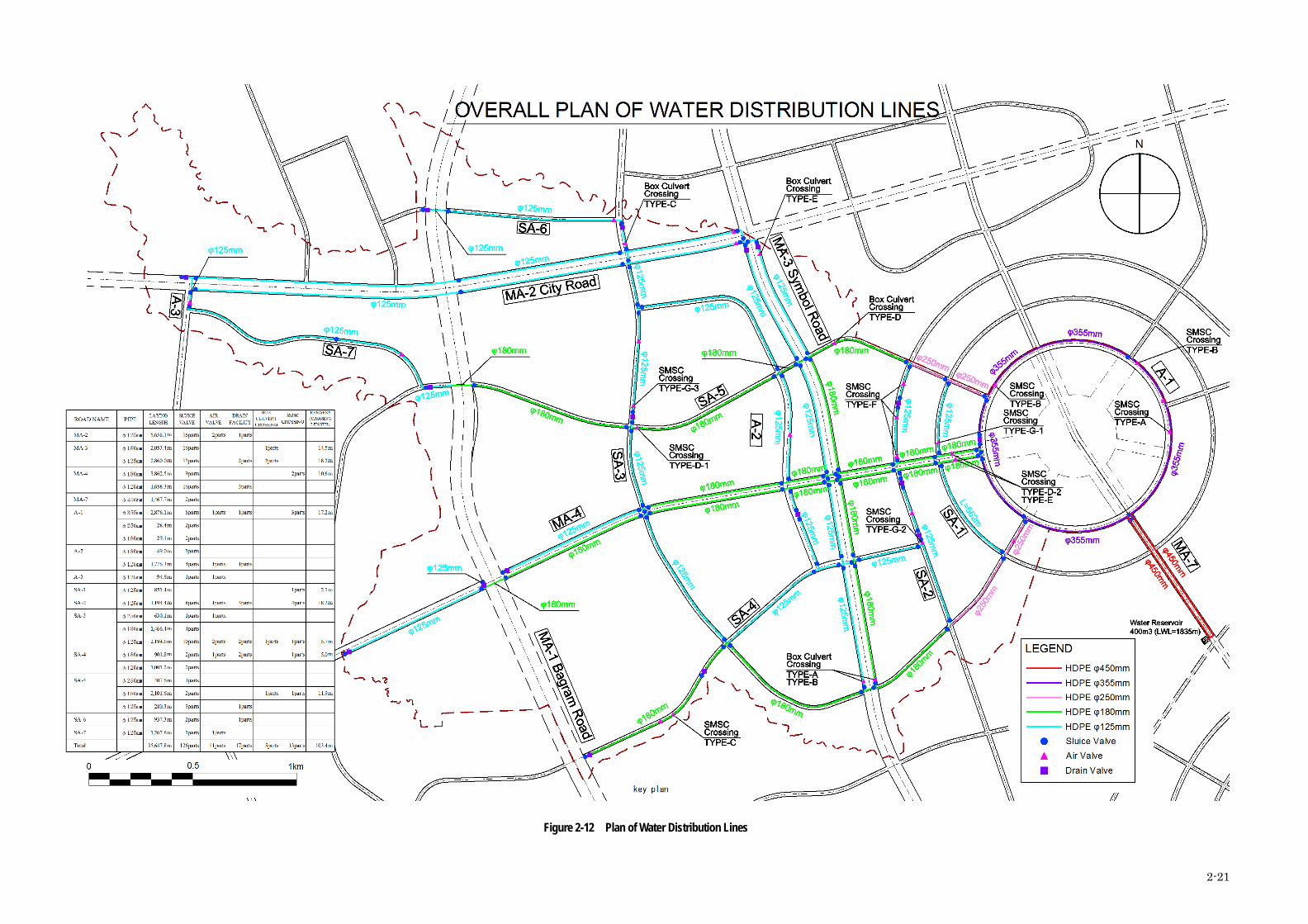
2-21
Figure 2-12 Plan of Water Distribution Lines

2-22
Figure 2-13 Plan of Principal Water Distribution Lines

2-23
Auxiliary Facility and Equipment 2.2.4
Table 2.17 shows the auxiliary facility and equipment concerning to the Project.
Table 2.17 Auxiliary Facility and Equipment
Priority Facility and Equipment Location Quantity, Application
1 Operators Station Building
Water Pressure Regulating Reservoir
1 Prefabricated house (3 x 2 m) for 2 or 3 persons
2 Maintenance tool
Pol-e Charikhi Well Station and Water Pressure Regulating Reservoir
1 General workshop tools (wrenches and drivers), specific tools (testers, cramp meters), power generators, welding machine etc.
3 Office furniture
Pol-e Charikhi Well Station and Water Pressure Regulating Reservoir
1 Desk, chair, PC, etc.
4 Spare pump for wells
Pol-e Charikhi Well Station
2 units Similar as PW-2
5 Security Room
Pol-e Charikhi Well Station
1 Prefabricated house (3 x 3 m)
6 Spare parts for pumps
Pol-e Charikhi Well Station
1 Spare parts for pumps such as gaskets, packing, and bearings
7 Spare valves Water Conveyance Pipeline and Transmission Main
1 Spare valves for water conveyance pipelines and transmission mains (sluice valves and air valves)
8 Water Quality Analysis Equipment
Pol-e Charikhi Well Station
3 sets For field analysis of water quality
9 Flow meter and chamber
Water Pressure Regulating Reservoir
1 For recording distribution flow
10 Solar Panel and battery
Water Pressure Regulating Reservoir
1 Electricity support for water pressure regulating reservoir
11 Automatic Water Level Detector
Monitoring Wells 4 For monitoring wells
12 Motor Cycle Pol-e Charikhi Well Station and Water Pressure Regulating Reservoir
3 For route inspection of transmission main (18 km) and communication with Water Pressure Regulating Reservoir
13 Hypochlorite Pol-e Charikhi Well
Station
1 Equivalent amount to 1 year consumption
Priority in Project Components 2.2.5
Considering the impact of the Project and urgency, the priority in the Project components is ranked as Table
2.18.
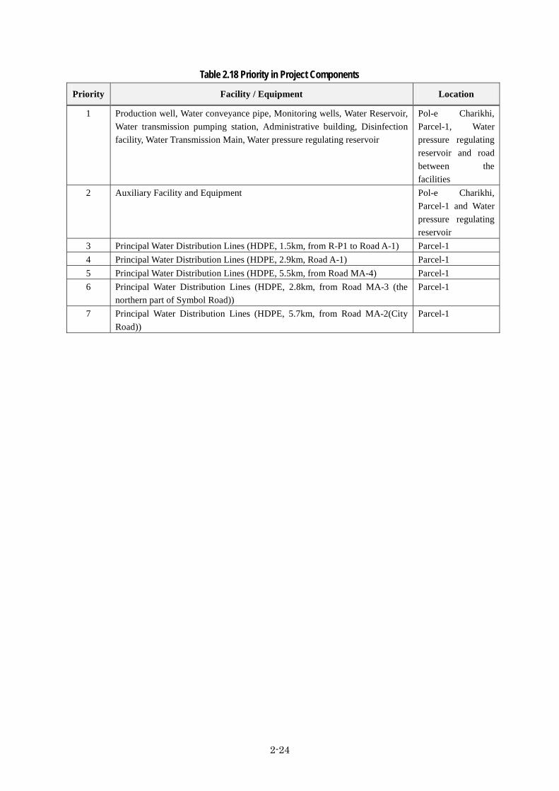
2-24
Table 2.18 Priority in Project Components
Priority Facility / Equipment Location
1 Production well, Water conveyance pipe, Monitoring wells, Water Reservoir, Water transmission pumping station, Administrative building, Disinfection facility, Water Transmission Main, Water pressure regulating reservoir
Pol-e Charikhi, Parcel-1, Water pressure regulating reservoir and road between the facilities
2 Auxiliary Facility and Equipment Pol-e Charikhi, Parcel-1 and Water pressure regulating reservoir
3 Principal Water Distribution Lines (HDPE, 1.5km, from R-P1 to Road A-1) Parcel-1 4 Principal Water Distribution Lines (HDPE, 2.9km, Road A-1) Parcel-1 5 Principal Water Distribution Lines (HDPE, 5.5km, from Road MA-4) Parcel-1 6 Principal Water Distribution Lines (HDPE, 2.8km, from Road MA-3 (the
northern part of Symbol Road)) Parcel-1
7 Principal Water Distribution Lines (HDPE, 5.7km, from Road MA-2(City Road))
Parcel-1

2-25
Outline Design Drawing 2.2.6
The basic design drawings of the Project are shown from the next page.
[List of Drawing] Drawing No. Drawing Title DSWS-01 Project Location Map DSWS-02 System Flow DSWS-03 General Layout of Pol-e Charikhi Well Station DSWS-04 Plain of Pol-e Charikhi Well Station DSWS-05 Structural Drawing of Wells DSWS-06 Plan of Water Pressure Regulating Reservoir (R-P1) DSWS-07 Structural Drawing of Water Pressure Regulating Reservoir (R-P1) DSWS-08 Plan of Principal Water Distribution Lines

Production Well No.2
Production Well No.1
DCDA (DEHSABZ-BARIKAB CITYDEVELOPMENT AUTHORITY
PROMOTION OF KABUL METROPOLITAN AREAINFRASTRUCTURE DEVELOPMENT
PARCEL-1 AREA OF PHASE-1ISLAMIC REPUBLIC OF AFGHANISTAN
JAPAN INTERNATIONAL COOPERATION AGENCYCTI ENGINEERING INTERNATIONAL CO., LTD.
YACHIYO ENGINEERING CO., LTD.
AFG/KBL/KNC D/B Ph 1-3/Pg 1-5/P1-11/CEO CIS/ / DCDA/CEO/2011/441/ 001
2-26
DSWS-01: Project Location Map

HDPE 500mmWater Transmission Main
HDPE 500mmWater Transmission Main
Pump Station Water Reservoir (R-Well)850m3 x 2 Basins
P
SS30
4
LS
125A
PI
P
LS
PI
DWL : GL+1771.7
1.8m3/min
1.8m3/min
Drain
Installation level shoud be less than LWL
Calcium Hypochlorite Dosing System
Water Transmission Pump
HWL=1783.5
Drain
Parcel-1
Water Pressure Regulating Reservoir
HWL=1839.6
400m3
DCDA (DEHSABZ-BARIKAB CITYDEVELOPMENT AUTHORITY
PROMOTION OF KABUL METROPOLITAN AREAINFRASTRUCTURE DEVELOPMENT
PARCEL-1 AREA OF PHASE-1ISLAMIC REPUBLIC OF AFGHANISTAN
JAPAN INTERNATIONAL COOPERATION AGENCYCTI ENGINEERING INTERNATIONAL CO., LTD.
YACHIYO ENGINEERING CO., LTD.
AFG/KBL/KNC D/B Ph 1-3/Pg 1-5/P1-11/CEO CIS/ / DCDA/CEO/2011/441/ 001
SYSTEM FLOW
(R-P1)
LWL=1835
HDPE 250mm
HDPE 180mm
Water Conveyance Pipe
Water Conveyance Pipe(Outer Diameter)
(Outer Diameter)
(Outer Diameter)
(Outer Diameter)
Drain
MM
LWL=1779.5
WL=1783.5
150A
125A
SS304
200A SS304
125A
SWL : GL+1773.93
GL+1767.7
DWL : GL+1778.4SWL : GL+1780.63
GL+1774.4
GL+1779.7
GL+1786.4
HWL=1783.5
LWL=1779.5
GL+1779.7
SS30
412
5A
Water Distribution Lines (HDPE)Drain
2-27
DSWS-02: System Flow
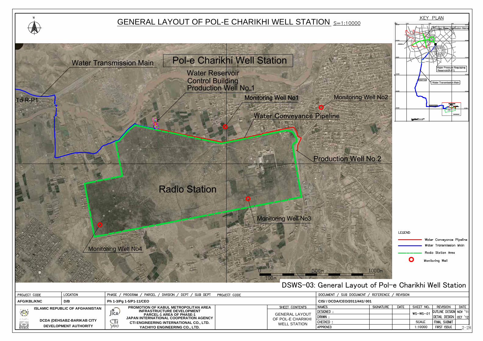
Monitoring Well No4
DCDA (DEHSABZ-BARIKAB CITYDEVELOPMENT AUTHORITY
PROMOTION OF KABUL METROPOLITAN AREAINFRASTRUCTURE DEVELOPMENT
PARCEL-1 AREA OF PHASE-1ISLAMIC REPUBLIC OF AFGHANISTAN
JAPAN INTERNATIONAL COOPERATION AGENCYCTI ENGINEERING INTERNATIONAL CO., LTD.
YACHIYO ENGINEERING CO., LTD.
AFG/KBL/KNC D/B Ph 1-3/Pg 1-5/P1-11/CEO CIS/ / DCDA/CEO/2011/441/ 001
OF POL-E CHARIKHIWELL STATION
GENERAL LAYOUT OF POL-E CHARIKHI WELL STATION
GENERAL LAYOUT
2-28
DSWS-03: General Layout of Pol-e Charikhi Well Station

Production Well:NO.1
New fence
New fence
New fence
Lavatory
Septic Tank
Flow Meter Chamber
GATE
4000
DCDA (DEHSABZ-BARIKAB CITYDEVELOPMENT AUTHORITY
PROMOTION OF KABUL METROPOLITAN AREAINFRASTRUCTURE DEVELOPMENT
PARCEL-1 AREA OF PHASE-1ISLAMIC REPUBLIC OF AFGHANISTAN
JAPAN INTERNATIONAL COOPERATION AGENCYCTI ENGINEERING INTERNATIONAL CO., LTD.
YACHIYO ENGINEERING CO., LTD.
AFG/KBL/KNC D/B Ph 1-3/Pg 1-5/P1-11/CEO CIS/ / DCDA/CEO/2011/441/ 001
Flow Meter Chamber
2-29
DSWS-04: Plain of Pol-e Charikhi Well Station

WELL STRUCTURE DRAWING
S=1:400
6000
34000
5770
223012000
40000
500
40000
DCDA (DEHSABZ-BARIKAB CITYDEVELOPMENT AUTHORITY
PROMOTION OF KABUL METROPOLITAN AREAINFRASTRUCTURE DEVELOPMENT
PARCEL-1 AREA OF PHASE-1ISLAMIC REPUBLIC OF AFGHANISTAN
JAPAN INTERNATIONAL COOPERATION AGENCYCTI ENGINEERING INTERNATIONAL CO., LTD.
YACHIYO ENGINEERING CO., LTD.
AFG/KBL/KNC D/B Ph 1-3/Pg 1-5/P1-11/CEO CIS/ / DCDA/CEO/2011/441/ 001
WELL STRUCTUREDRAWING
1000
(X=532,609 Y=3822,310)
2-30
DSWS-05: Structural Drawing of Wells

1815.00
1814.00
1813.00
1814
.00
1815
.00
1815.00
1816.00
Perforated pipe PVC 100mm
Gravel trench 0.5mx0.5mx20m
30000
30000 Water Transmission Main HDPEφ500mm
(Outer diameter)
2250
2800
1500
1500
New fence
Septic Tank
Lavatory
New fence
New fence
Gate
New fence
FGL+1814.0Drain Pit
DCDA (DEHSABZ-BARIKAB CITYDEVELOPMENT AUTHORITY
PROMOTION OF KABUL METROPOLITAN AREAINFRASTRUCTURE DEVELOPMENT
PARCEL-1 AREA OF PHASE-1ISLAMIC REPUBLIC OF AFGHANISTAN
JAPAN INTERNATIONAL COOPERATION AGENCYCTI ENGINEERING INTERNATIONAL CO., LTD.
YACHIYO ENGINEERING CO., LTD.
AFG/KBL/KNC D/B Ph 1-3/Pg 1-5/P1-11/CEO CIS/ / DCDA/CEO/2011/441/ 001
RESERVOIR(R-P1)
PLAN OF WATER PRESSURE REGULATING RESERVOIR (R-P1)
2-31
DSWS-06: Plan of Water Pressure Regulating Reservoir (R-P1)

DL=1810.0
HWL▽+1839.6
16800
LWL▽+1835.0
9800
16000
226
00
324
002000
2000
DCDA (DEHSABZ-BARIKAB CITYDEVELOPMENT AUTHORITY
PROMOTION OF KABUL METROPOLITAN AREAINFRASTRUCTURE DEVELOPMENT
PARCEL-1 AREA OF PHASE-1ISLAMIC REPUBLIC OF AFGHANISTAN
JAPAN INTERNATIONAL COOPERATION AGENCYCTI ENGINEERING INTERNATIONAL CO., LTD.
YACHIYO ENGINEERING CO., LTD.
AFG/KBL/KNC D/B Ph 1-3/Pg 1-5/P1-11/CEO CIS/ / DCDA/CEO/2011/441/ 001
SPT
10 20 30 40 50(m) DEPTH
GRAPHICIOG
Blow CountBlow/cm
18
27
50
50
50
50
26
31
38
50
02
03
04
05
06
07
08
09
10
01
SOIL
DESCRIPTION
Silt With
Lean Clay
Silt Clay
Silt Clay
62% Gravel
Silt Clay
43% Gravel
Silt Clay
48% Gravel
Silt Clay
36% Gravel
Silt Clay
Silt Clay
Silt Clay
DL=1810.0
6300
FGL▽+1814.0
New Fence
New Fence
Transmission Main 450A
Distribution Main 400A
Overflow 250A
2-32
DSWS-07: Structural Drawing of Water Pressure Regulating Reservoir (R-P1)

0 1km0.5
N
LEGEND
HDPE φ180mmHDPE φ125mmSluice ValveAir ValveDrain Valve
HDPE φ355mmHDPE φ450mm
HDPE φ250mm
DCDA (DEHSABZ-BARIKAB CITYDEVELOPMENT AUTHORITY
ISLAMIC REPUBLIC OF AFGHANISTAN
JAPAN INTERNATIONAL COOPERATION AGENCYCTI ENGINEERING INTERNATIONAL CO., LTD.
YACHIYO ENGINEERING CO., LTD.
AFG/KBL/KNC D/B Ph 1-3/Pg 1-5/P1-11/CEO
DS-OP-01
AS SHOWN
PARCEL-1
DISTRIBUTION MAIN
CIS/ / DCDA/CEO/2011/441/ 001
OVERALL PLAN OF
OVERALL PLAN OF PRINCIPAL WATER DISTRIBUTION LINES
PRINCIPAL WATERDISTRIBUTION LINES
2-33
DSWS-08: Plan of Principal Water Distribution Lines

2-34
Implementation Plan 2.2.7
Implementation Policy 2-2-7-1The Project will be implemented according to the scheme of Japan’s grant aid for conflict prevention and peace building. Accordingly, unlike ordinary grant aid projects, execution of the works will be conducted by local contractors.
The United Nations Office for Project Services (UNOPS) is assumed as the procurement agent in the Project implementation stage.
Implementation setup (1)Following the Exchange of Notes (E/N) and signing on the Grant Agreement (G/A), the Government of Afghanistan will consign the procurement agent to select and bind a contracts with the contractors. Consultant in charge of construction supervision and contractor(s) will enter their contracts with the procurement agent for their implementation of works.
(a) Implementing Agency The responsible implementing agency for the Project will be DCDA.
The Project will be implemented based on the Agent Agreement (A/A) that is signed between DCDA and the procurement agent. In this scheme, DCDA will have overall control over the grant aid project for conflict prevention and peace building and will be responsible for facilitating smooth project implementation as the contract partner of the procurement agent. Moreover, the JICA Office in Afghanistan and procurement agent will establish a working group in Afghanistan to check the progress and hold discussions on technical confirmation items. The implementation scheme is indicated in Figure 2-14.
Figure 2-14 Implementation Scheme
Contractors Report
DCDA
Construction Contract
Agent Agreement
E/N G/A
Consultative Committee
Construction Supervision TeamSupervision
Procurement Agent (UNOPS)
JICA Afghanistan
Office
JICA Headquarter
Office
Japan Government
Japanese
Embassy
Afghanistan Government (The Government of recipient country)
Implementation

2-35
(b) Procurement Agent UNOPS will manage the tender and conduct works supervision in its capacity as the procurement agent. UNOPS has a local office in Kabul.
When conducting works supervision, in other projects in Afghanistan, UNOPS directly recruits works supervision engineers from third countries and Afghanistan, and a team organized within UNOPS conducts the actual supervision work.
Tender System (2)Since the Project works will basically be conducted using methods, specifications and materials, etc. that are commonly used in Afghanistan, local construction companies will be able to comfortably implement them.
UNOPS will implement the bidding. The works are implemented by a local construction company selected in general competitive bidding or limited competitive bidding.
There is a number of water relating facility construction project in Afghanistan under assistance of international donors such as USAID, WB, UN, KfW, etc. Under these projects pipelines, RC structure reservoirs and pump facilities are constructed. Although the project cost of the majority of the projects are less than US$ 10 million, there are some large scale projects with the scale of US$ 30 million or US$ 40 million.
Contract Method (3)In similar projects implemented by UNOPS in Afghanistan, Lump Sum contract is widely employed. Because this Project embraces a number of uncertain factors such as detailed locations of Baba Khushkhar Road, several variation orders in quantities of works may be expected. Therefore, introduction of quantitative method such as BQ contract will be discussed with UNOPS.
The contract currency will be United States dollars (USD).
Implementation Conditions 2-2-7-2 Construction Supervision (1)
Since it is assumed local contractors will execute the works, it is necessary to strengthen the capacity for supervision particularly on quality control, construction management and safety control.
The cost for construction supervision is, therefore, accounted in the Project cost.
Site Adapt Method (2)Site adapt method is commonly employed in Afghanistan in order to correspond to variation order depending on the site conditions. There are some facilities designed under uncertain condition in this Project. Particularly the line shape and earth cover of transmission mains shall be flexibly adjusted to the site condition. Therefore, application of site adapt method is recommended.
Scope of Works (3)Table 2.19 shows the scope of works to be undertaken by the Japanese side and the Afghan implementing agency for construction of the facilities.

2-36
Table 2.19 Scope of works
No. Work Item Japanese Side
Afghan Side Remarks
1. Wells, Water Transmission and Distribution Facilities
(1) Securing site and discussion on use of the land Before Exchange of Note (E/N)
(2) Survey and removal of mines and unexploded
bombs Before commencement of work by the grant aid
(3) Removal and relocation of the existing facilities
Before commencement of work by the grant aid
(4) Construction of the facilities - Production Wells - Transmission Main - Monitoring Wells - Reservoir - Transmission Pump Facility - Control Building - Disinfection Facility - Conveyance Pipeline - Water Pressure Control Reservoir - Principal Water Distribution Lines
Including civil and architectural works, procurement of equipment and trial operation
(5) Electricity cabling to the middle voltage switchgear (approx. 150 m from the production well (PW-2))
DABS
(6) Pavement of internal road at the site (7) Security lighting (Pol-e Charikhi Station) (8) Security lighting (Water pressure Regulating
Reservoir)
(9) Drainage facility for general effluent (10) Planting in the site After the works by the
grant aid (11) Construction of fences and gates (12) Construction of security guard building (13) Installation of fire extinguisher (14) Procurement of office furniture (15) Provision of electricity power and water required
for trial operation
2. Import and Transportation of Materials and Equipment for Facility Construction
(1) Procurement of Materials and Equipment (2) Sea Transportation (3) Custom Clearance, Tax Exemption and customs
bond for storage According to E/N
(4) Inland transportation in Afghanistan :locus of responsibility
Construction Supervision 2-2-7-3 Local Consultant (1)
There are few consulting firms in Afghanistan and it is difficult to secure appropriate engineers required for supervision of the construction. There has been no quality control standard established, sufficient experience in construction supervision and advanced engineering skills are required for this
2-37
Project. Therefore, it is highly recommended to employ international consultant for supervision works including quality control, schedule and progress management and safety control. Under the supervision by the international consultants, local consultants will supervise the works at the site.
Implementation Setup (2)(a) Implementation design period (tender period)
Tender process will be conducted by UNOPS. However, consultants employed by UNOPS shall assist answering to the technical question from bidders, evaluation of technical proposal, and other technical aspects.
(b) Works supervision period During the construction phase, the consultant will conduct the necessary onsite guidance and technical guidance centering on the quality supervision, progress supervision and safety supervision required for Project implementation. It will provide reports on the works progress and work contents to the procurement agent and DCDA, and propose discussions, investigations and solutions in cases where technical problems arise.
(c) Works supervision setup A supervision office will be established in Kabul city or Dehsabz area. Throughout the construction period, a Project Manager will be assigned and supervise the construction works together with construction supervision team consisting of engineers specialized in pipelines, networks, structures, etc.
Quality Control Plan (3)The works supervision team organized by UNOPS will implement quality control assuming the following major quality control items as of Table 2.20.
.

2-38
Table 2.20 Main Quality Control Plan Construction
name QC items Inspection Method Frequency
Earth work Degree of compaction visual inspection each after compaction
Backfilling work Carried soil test grain size test 1 item / borrow pit
Formwork Finishing work visual, dimension inspection and photo all member
Reinforcement works
Material mill certification report every after carrying in
Assembly test visual inspection (pitch and cover thickness) all member
Concrete work
Material
cement :intensity test each parts aggregate :grain size test
water :quality test of water (as need arises)
Trial batch concrete temperature, slump and air content
before placing concrete laboratory sample
(1sample/day)
or compressive strength test
laboratory sample (1sample/day)
Plant data site sealed box cure 7 and 28 days later
Asphalt pavement work Material aggregate density test before construction work
Base course work Material grain size test before construction work
Pipeline Works Material factory test before delivery of goods
Finished work laying location / water pressure test per certain construction quantity
Procurement Plan (4)
Procurement of materials for construction works is included in the contract of construction with the contractors, procurement will be conducted based on the contract between the procurement agency and contractor. The suppliers of construction materials and equipment are assumed as shown in the table below.

2-39
Table 2.21 Suppliers of construction materials and equipment
Name of materials and equipment
Country of origin Remarks Local Japan Third
country[Materials]
Reinforcement bars Import from Russia, etc.
Cement Import from Pakistan, etc.
Concrete aggregates
Asphalt Iran, Pakistan, Uzbekistan, etc.
Road marking Pakistan, India, etc.
HDPE Pipeline Saudi Arabia, etc.
PVC Pipeline
Valves Germany
Pumps Japan, Italy, Germany, Sweden
Switchgear Germany, France, etc.
Transformer Germany, U.S.A, etc.
Instruments Germany
Main Control Panel U.S.A, etc.
Motor U.S.A, U.K, etc.
Chlorine injection system Italy, Sweden, etc.
Well Casing Import from the U.S.A., etc. PVC can be procured in local market
Precast Manhole
Ratio 96.9% 0.0% 3.1%
Note: Ratio is expressed by cost
Transportation route
The transportation route differs based on the availability in market and importers. The grant aid will cover transportation cost.
Route from Iran
i) Inside Iran to Dogarun (at border) ii) Transfer of goods from Iranian trucks to Afghan Trucks at Afghanistan
Islam Qala (at border) 6 days iii) Islam Qala to Herat 3 days iv) Herat to Kandahar 3 days v) Kandahar to Kabul 3 days
Route from Karachi
i) Country of origin to Karachi ii) Procedures taken in Karachi 10 days iii) Karachi to Peshawar 5 days (including two days for the
procedures in Peshawar) iv) Peshawar to Torkham (national border) 4 days v) Torkham to Kabul 2 days vi) Customs clearance in Kabul 2 - 3 days

2-40
vii) Transport inside Kabul 1 day
Route from Uzbekistan
i) Country of origin to Hairatan 3 days ii) Procedures in Hairatan 1 day iii) Hairatan to Kabul 2 days
Additional one (1) week is necessary for the procedure for tax benefit.
Operational Guidance Plan 2-2-7-4AUWSSC has supplied water toward approximately 140,000 customers. Therefore, it is understood that AUWSSC has acquired basic skills on operation and maintenance of water supply facilities and enables to conduct daily operation and maintenance works. However, the items to be procured under this Project require special operation and maintenance procedures. Therefore, initial operation training by the contractor(s) is essential for smooth and efficient operation after hand over.
Soft Component (Technical Assistance) Plan 2-2-7-5There will be no soft component plan in the Project. However, a technical cooperation project for strengthening the operation and maintenance capacity of AUWSSC as a part of Greater Kabul Development Project is expected to be commenced from 2014.
Implementation Schedule 2-2-7-6As shown in Table 2.22, tender process requires 6.5 months and construction works require 14.5 months after handing the detailed design to the procurement agent (UNOPS). However, suspension of construction works during winter season should be taken account.
Table 2.22 Project implementation processes 1 2 3 4 5 6 7 8 9 10 11 12 13 14 15 16 17 18 19 20 21 22
Tender
Construction & Procurement
(Tender Period 6.5 months)
Tender Document / Cost Estimation / Construction Planning
Announce / PQ/ Tender / Evaluation
Contract
(Construction Works: 14.5 month)(Actual: 11.5 months)Preparatory
Construction Works
Trial / Inspection / Handover
Post works
Winter Suspension (December – February)
E/N, G/A, A/A

2-41
2.3. Obligations of Recipient Country
Following the E/N, the Afghanistan side will undertake the following items in cooperation between the responsible agency and implementing agencies.
General Items 2.3.1
Ensure the necessary conveniences for Project officials (Japanese and third country nationals) regarding their entry to, stay and safety in Afghanistan.
Exempt/Bear any tariffs or domestic taxes that may otherwise be levied on services, materials and Japanese nationals concerned with the Project.
Properly operate the facilities that are constructed under the Japan’s grant aid, and make sure that appropriate maintenance is continued.
Bear all the costs that are required under the Project but are not covered by the Japan’s grant aid.
Ensure relocation of facilities, etc. located in the Project area under the implementing agency’s own responsibility and authority
Special Items 2.3.2
The obligation and responsibility of DABS covers securing the sites of the middle voltage switchgear which is approximately 150 m away as well as cabling to the switchgear. The Project shall execute cabling works from the switchgear in 10 kV. The power feeding facilities, which will be constructed by the Project, shall be constructed as a property of DCDA and transferred to AUWSSC together with the pump facilities. AUWSSC will be responsible for operation and maintenance of the water supply facilities.
DCDA will be responsible for giving advance explanations to roadside residents and seeking their cooperation (prior to construction).
In cases where it is necessary to obtain authorization from government agencies and so on, the necessary applications will be made.
Removal of mines and unexploded bombs
2.4. Project Operation Plan
Responsible Setup in Afghanistan 2.4.1
AUWSSC is responsible for operation and maintenance of this Project including distribution networks. Since the target area is relatively small and Pol-e Charikhi is close to Kabul, Kabul branch office of AUWSSC will be in charge of operation and maintenance of the facilities to be constructed in the Project.
The Kabul branch office has currently planned to establish a new sub-section for the new city in charge of water supply of Pol-e Charikhi system. This new organization is expected to be a model case of operation and maintenance of water supply and sewerage works in the future new city. Table 2.23 and Table 2.24 show the required personnel in the department of sales & customers relations and the

2-42
department of O&M, respectively.
Table 2.23 Required Personnel in department of sales & customers relations Position Number Remarks
Section Manager 1 BA. in Business Administration Meter reader / cash tariff collector 6 14.3 collectors per 100,000 population
Total 7
Table 2.24 Required Personnel in department of O&M Position Number Remarks
Department Director (in charge for the New City)
1 B.Eng. in Engineering
Pre-Charikhi Well Station Section Wells, Reservoirs, Pumps and Transmission Mains
Section Manager 1 B.Eng. in Engineering Technician 5 1 person x 3 shifts Clerk 2 Miscellaneous worker 9 2 persons x 3 shifts
Security 13 3 persons x 3 shifts 2 for PW1 and 1 for PW2
Network & Pipeline Section Water Pressure Regulating Reservoir and Distribution Networks
Section Manager 1 B.Eng. in Engineering Technician 5 1 person x 3 shifts Miscellaneous worker 9 2 persons x 3 shifts Water Quality Management Section Section Manager (Chief Analyst) 1 B.Eng. in Engineering or BSc in Chemistry
Total 47
Basic Policy 2.4.2
For long-term effective use of the facilities constructed under the Project and stably and continuous water supply with reflecting the change in daily demand, operation, management and protection of facility environment are indispensable. The Afghan side should carry on appropriate protection and maintenance of the facilities and the equipment derived from increase in reliability, safety and effectiveness for preserving the ability and the function of the facilities and the equipment, and constant water supply. Figure 2-15 shows the basic policy of maintenance of the facility in the Project.

2-43
Figure 2-15 Maintenance Flow of Water Supply Facilities
Items for Regular Check 2.4.3
Based on the policy mentioned above, the following points are the basic items that AUWSSC shall conduct operational and maintenance management of the water supply facilities. Figure 2-15 shows the main items for O&M of the new water supply facilities.
Operation Management: Carrying on operation and control under normal circumstances Maintenance Management: Carrying on maintenance, repair and prepare so that the facility,
equipment and device can show full ability for operation.
Table 2.25 Main Items for Operation and Maintenance (O&M) Classification Main Management Item
Operation Management
1) Water volume control: Controlling equipment and devices conforming to the design water volume
2) Water quality control: Measuring raw water and check whether treated water meets the design water quality standard (pH, Electrical conductivity, Turbidity, Color and Odor: daily). Measuring residual chlorine after disinfection and confirming whether it becomes lower than the value at the reservoir, water pressure regulating reservoir and hydrant. After the measurement, resetting injection rate of disinfection reagent, if required.
Maintenance 1) Inspection Item: Inspecting and checking facilities, equipment and devices with meters and naked eyes and repairing and maintaining faults or breakdowns. Additionally securing and protecting safety of chemicals (chlorine) needed for disinfection.
2) Prevention: Renewing facilities, equipment and devices periodically depending on the importance and characteristics even without any breakdowns. This leads to safe and secure operation since ensuring reliability and safety over facilities, equipment and devices may increase.
Start
End
Diagnose (Evaluation)
No
(Poor maintenance)
No
(Defect)
Yes
(Normal)
Yes
(Normal)
No
(Large Impact)
(Degradation of functions)
(Trouble / Accident)
(No possibility for maintenance)
(Source: Guideline for Maintenance of Water Supply Facilities)
Maintenance / Repair
Replacement
Operation &
Management
Routine Inspection /
Patrol Inspection

2-44
AUWSSC is required to carry on appropriate operation and maintenance of equipment according to O&M manuals of equipment supplied by production makers. Table 2.26 indicates the standard checking items of pumps and power receiving equipment as the main equipment for water supply facilities, respectively.
Table 2.26 Standard Check List for Pump Equipment
Pum
p
Daily (during operation) Record in operation diary (distribution volume, check with naked eyes,
abnormal noise, shaft temperature, leakage, pressure of inflow and outflow)
Monthly Check of shaft oil and grease
Check of gland packing
Every 6 months
Replacement or refilling of shaft oil and grease
Precision of the shaft center Measurement of vibration and noise
Tightening each part of the equipment
Every year Dismantling check (vibration of rotating parts, aperture of gliding parts, corrosion of inside, choking with substances, paint)
Check of accessories and spares
Mot
or
Daily (during operation) Record in operation diary (electrical currency, check with naked eyes,
abnormal noise, shaft temperature, leakage)
Every 6 months Refilling of shaft grease Measurement of vibration and noise
Check of temperature of shaft
Every year Check of shaft holder Measurement of non-conductance resistance value
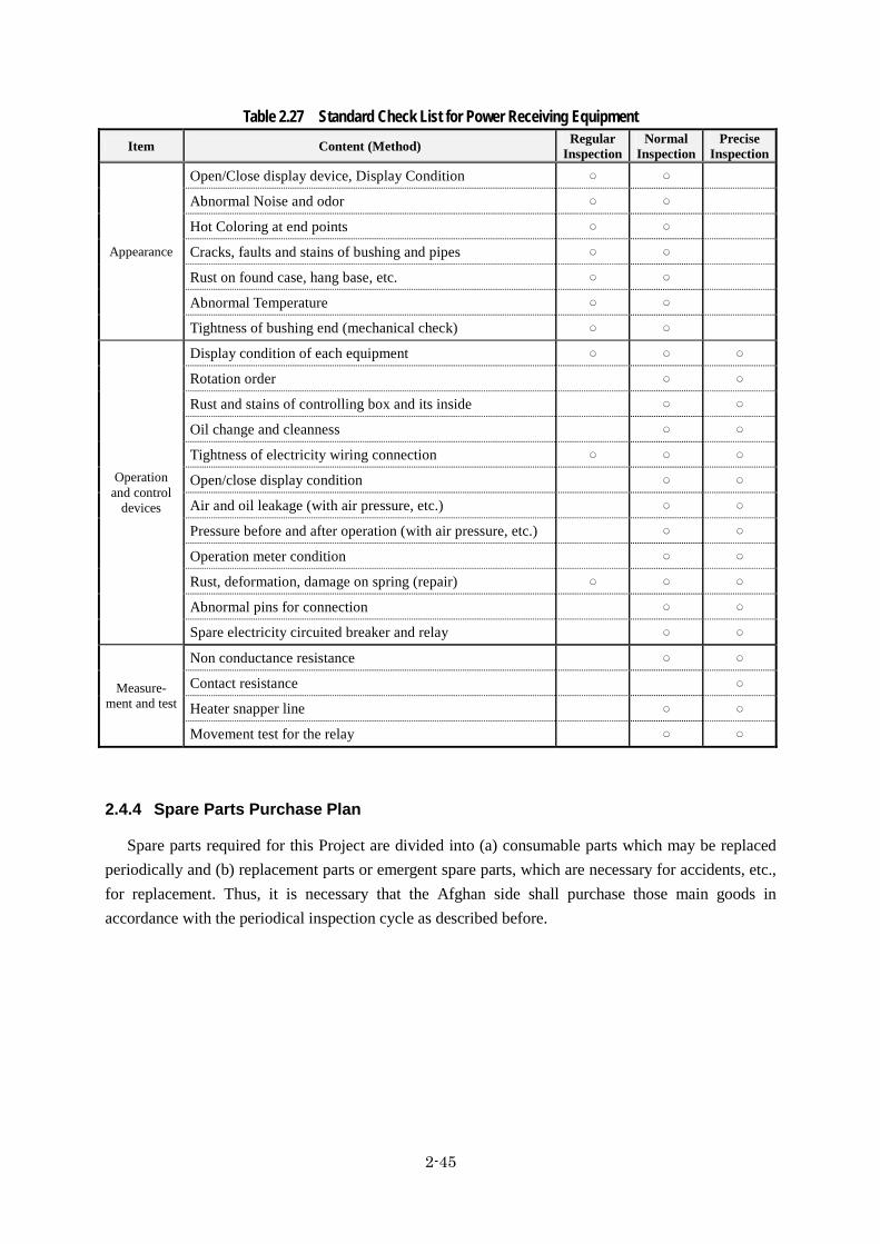
2-45
Table 2.27 Standard Check List for Power Receiving Equipment Item Content (Method) Regular
InspectionNormal
InspectionPrecise
Inspection
Appearance
Open/Close display device, Display Condition
Abnormal Noise and odor
Hot Coloring at end points
Cracks, faults and stains of bushing and pipes
Rust on found case, hang base, etc.
Abnormal Temperature
Tightness of bushing end (mechanical check)
Operation and control
devices
Display condition of each equipment
Rotation order
Rust and stains of controlling box and its inside
Oil change and cleanness
Tightness of electricity wiring connection
Open/close display condition
Air and oil leakage (with air pressure, etc.)
Pressure before and after operation (with air pressure, etc.)
Operation meter condition
Rust, deformation, damage on spring (repair)
Abnormal pins for connection
Spare electricity circuited breaker and relay
Measure- ment and test
Non conductance resistance
Contact resistance
Heater snapper line
Movement test for the relay
Spare Parts Purchase Plan 2.4.4
Spare parts required for this Project are divided into (a) consumable parts which may be replaced periodically and (b) replacement parts or emergent spare parts, which are necessary for accidents, etc., for replacement. Thus, it is necessary that the Afghan side shall purchase those main goods in accordance with the periodical inspection cycle as described before.

2-46
2.5. Project Cost
Cost to be Borne by Japanese Side 2.5.1
This information is closed due to the confidentiality.
Cost to be Borne by Afghanistan Side 2.5.2
Total estimated Cost: 420 million Japanese Yen (Unit: Thousand AFA)
Contents Quantity Cost (Local Currency) Remarks Bank Commission for opening bank account
1 1,699 (Approx. 3 million yen)
DCDA
Other distribution mains which are excluded from the grant aid project
Approx. 17.2km
84,045 (Approx. 127 million yen)
DCDA
Other distribution branch lines which are excluded from the grant aid project
Approx. 160km
estimated
192,253 (Approx. 290 million yen)
Private Developers
Total 277,997 (Approx. 420 million yen)
Conditions for Cost Estimation 2.5.3
The conditions for cost estimation are shown below; 1. Date : November, 2012 2. Exchange Rate : US$ = 79.99 YEN
1AFA = 1.507 YEN 3. Construction Period : Construction period is shown as Table 2.22 4. Tax : As of Japanese Grant Aid scheme
Operation and Maintenance Cost 2.5.4
Operation and Maintenance Cost 2-5-4-1Table 2.26 shows the operation and maintenance costs for the well pumps, transmission pump
facility and reservoirs consisting of labor cost, electricity tariff, cost for chemicals (chlorine) and contingency for procurement of spare parts. The total amount is expected at approximately 46 thousands AFA per year.

2-47
Table 2.28 Operation and Maintenance Cost Item Cost (USD/y) Remarks
Labor Cost 12,400 Only direct operators Energy 13,860 O&M Cost 508 2% of construction cost of electro-mechanical
facilities Miscellaneous Cost 6,200 50% of Labor cost (overhead including transport
and office consumables) Chemicals for Disinfection
185
Depreciation Cost 11,823 Emergency Generation 1,386
Total 46,362 Note: Operation cost of the facility for 5,000 m3/day
Renewal Plan for Mechanical and Electrical Equipment 2-5-4-2In this Project, main equipment such as borehole pumps, water transmission pumps and electrical
equipment related to power receiving will be installed in the related facilities. These mechanical and electrical equipment are expected to be replaced in the period defined in Table 2.29.
Table 2.29 Renewal Plan for Mechanical and Electrical Equipment Equipment Name Category Expected Service Life
Borehole Pump Submersible pump
10 years
Water Transmission Pump
Surface pump 15 years
Electrical Equipment 15 years
Budget Security 2-5-4-3The operation and maintenance cost per unit water supply is equivalent to approximately 25
AFA/m3. Since the national water tariff for water service is 25.00 AFA/m3, required cost for operation and maintenance can be secured by the tariff.

3-1
Project Evaluation Chapter 3
3.1. Preconditions
The critical path of the Project includes land acquisition for the construction site and discussion with road management authority on road occupation for laying pipelines by DCDA as the executing agency.
3.2. Necessary Inputs by Recipient Country
The Afghan side is responsible for land acquisition for the construction site and discussion with road management authority on road occupation for pipelines.
3.3. Important Assumptions
Anti-governmental activities have frequently occurred in Afghanistan. Therefore, the important assumption is securing the facilities during construction works and post-construction works. Abduction targeting foreign engineers has also frequently occurred and there is possibility that foreign engineer’s travel to Afghanistan may become difficult. Such background reveals the Project accomplishment largely depends on security conditions.
3.4. Project Evaluation
Relevance 3.4.1
This Project is relevant to the needs of Afghanistan and development policy as well as Japan’s assistance policy. This Project will contribute to secure required water for the Parcel 1 and will be a model case for development of the new city. Therefore, the relevance is evaluated as high.
Effectiveness 3.4.2
Quantitative Project Evaluation 3-4-2-1
Table 3.1 Quantitative Project Evaluation Indicator Current Condition(2012) Index(2018)
[3 years after commission]
Water supply (m3/day) 0 5,000 Service Population 0 42,000 Water Supply Hours (Hour / Day) 0 24
Qualitative Project Evaluation 3-4-2-2Construction of water supply and transmission facility will promote the development of Parcel-1
area.

[Appendices]

Appendix-1: Member List of the Study Team
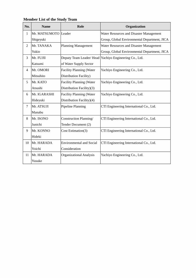
Member List of the Study Team
No. Name Role Organization
1 Mr. MATSUMOTO
Shigeyuki
Leader Water Resources and Disaster Management
Group, Global Environmental Department, JICA
2 Mr. TANAKA
Yukio
Planning Management Water Resources and Disaster Management
Group, Global Environmental Department, JICA
3 Mr. FUJII
Katsumi
Deputy Team Leader/ Head
of Water Supply Sector
Yachiyo Engineering Co., Ltd.
4 Mr. OMORI
Mitsuhito
Facility Planning (Water
Distribution Facility)
Yachiyo Engineering Co., Ltd.
5 Mr. KATO
Atsushi
Facility Planning (Water
Distribution Facility)(3)
Yachiyo Engineering Co., Ltd.
6 Mr. IGARASHI
Hideyuki
Facility Planning (Water
Distribution Facility)(4)
Yachiyo Engineering Co., Ltd.
7 Mr. ATSUJI
Manabu
Pipeline Planning CTI Engineering International Co., Ltd.
8 Mr. ISONO
Junichi
Construction Planning/
Tender Document (2)
CTI Engineering International Co., Ltd.
9 Mr. KONNO
Hideki
Cost Estimation(3) CTI Engineering International Co., Ltd.
10 Mr. HARADA
Yoichi
Environmental and Social
Consideration
CTI Engineering International Co., Ltd.
11 Mr. HARADA
Yusuke
Organizational Analysis Yachiyo Engineering Co., Ltd.

Appendix-2: Study Schedule

Study Schedule Date Stay Schedule
NOV 20,
2012 TUE In-flight Departure from Japan (Mr. Harada Yusuke)
NOV 21 WED Kabul Arriving at Kabul (Mr. Harada Yusuke)
NOV 22 THU Kabul Analysis of collected data
NOV 23 FRI Kabul Analysis of collected data
NOV 24 SAT Kabul Study for organization of operation and maintenance in AUWSSC
NOV 25 SUN Kabul Study for organization of operation and maintenance in AUWSSC
NOV 26 MON Kabul/
In-flight
Study for organization of operation and maintenance in AUWSSC
Departure from Japan (Mr. Harada Yoichi)
NOV 27 TUE Kabul Study for organization of operation and maintenance in AUWSSC
Arriving at Kabul (Mr. Harada Yoichi)
MOV 28 WED Kabul
Study for organization of operation and maintenance in AUWSSC
Study for conditions of environmental permit by NEPA and land
acquisition
NOV 29 THU Kabul Analysis of collected data
NOV 30 FRI Kabul Analysis of collected data
DEC 1 SAT Kabul/
In-flight
Study for organization of operation and maintenance in AUWSSC
Study for conditions of environmental permit by NEPA and land
acquisition
Departure from Japan (Mr. Isono)
DEC 2 SUN Kabul
Study for organization of operation and maintenance in AUWSSC
Study for conditions of environmental permit by NEPA and land
acquisition
Arriving at Kabul (Mr. Isono)
DEC 3 MON Kabul/
In-flight
Study for organization of operation and maintenance in AUWSSC
Study for conditions of environmental permit by NEPA and land
acquisition
Study for construction planning
Departure from Japan (Mr. Atsuji)
DEC 4 TUE Kabul
Study for organization of operation and maintenance in AUWSSC
Study for conditions of environmental permit by NEPA and land
acquisition
Study for construction planning
Arriving at Kabul (Mr. Atsuji)

Date Stay Schedule
DEC 5 WED Kabul
Study for organization of operation and maintenance in AUWSSC
Study for conditions of environmental permit by NEPA and land
acquisition
Study for construction planning
Study for conditions of pipeline planning at DCDA
DEC 6 THU Kabul Analysis of collected data
DEC 7 FRI Kabul Analysis of collected data
DEC 8 SAT Kabul/
In-flight
Study for organization of operation and maintenance in AUWSSC
Study for conditions of environmental permit by NEPA and land
acquisition
Study for construction planning
Study for conditions of pipeline planning at DCDA
Departure from Japan (Mr. Fujii)
DEC 9 SUN Kabul/
In-flight
Study for organization of operation and maintenance in AUWSSC
Study for construction planning
Study for conditions of pipeline planning at DCDA
Arriving at Kabul (Mr. Fujiii)
Departure from Kabul (Mr. Harada Yoichi)
DEC 10 MON Kabul
Study for organization of operation and maintenance in AUWSSC
Study for construction planning
Study for conditions of pipeline planning at DCDA
Explanation of “Outline Design Report (Draft)” to DCDA &
AUWSSC
Arriving in Japan (Mr. Harada Yoichi)
DEC 11 TUE Kabul
Study for organization of operation and maintenance in AUWSSC
Study for construction planning
Study for conditions of pipeline planning at DCDA
Explanation on “Outline Design Report (Draft)” to DCDA &
AUWSSC
DEC 12 WED Kabul/
In-flight
Study for organization of operation and maintenance in AUWSSC
Study for construction planning
Study for conditions of pipeline planning at DCDA
Explanation on “Outline Design Report (Draft)” to DCDA &
AUWSSC
Departure from Japan (Mr. Matsumoto & Mr. Tanaka)
DEC 13 THU Kabul/
In-flight
Analysis of collected data/ Internal meeting
Arriving at Kabul (Mr. Matsumoto & Mr. Tanaka)
Departure from Kabul (Mr. Atsuji)
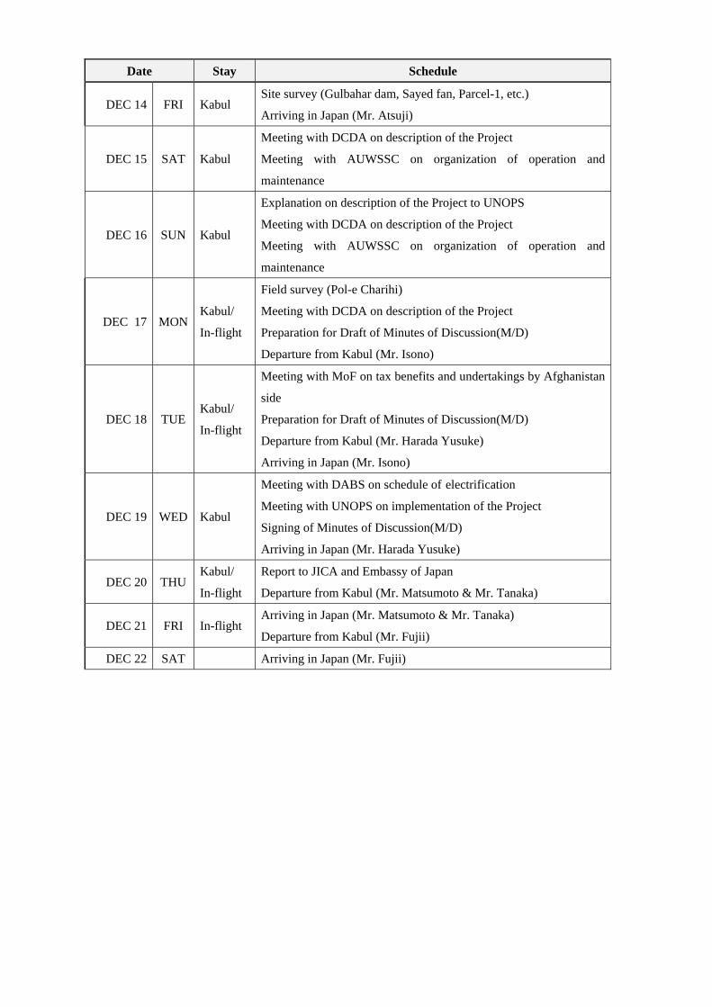
Date Stay Schedule
DEC 14 FRI Kabul Site survey (Gulbahar dam, Sayed fan, Parcel-1, etc.)
Arriving in Japan (Mr. Atsuji)
DEC 15 SAT Kabul
Meeting with DCDA on description of the Project
Meeting with AUWSSC on organization of operation and
maintenance
DEC 16 SUN Kabul
Explanation on description of the Project to UNOPS
Meeting with DCDA on description of the Project
Meeting with AUWSSC on organization of operation and
maintenance
DEC 17 MON Kabul/
In-flight
Field survey (Pol-e Charihi)
Meeting with DCDA on description of the Project
Preparation for Draft of Minutes of Discussion(M/D)
Departure from Kabul (Mr. Isono)
DEC 18 TUE Kabul/
In-flight
Meeting with MoF on tax benefits and undertakings by Afghanistan
side
Preparation for Draft of Minutes of Discussion(M/D)
Departure from Kabul (Mr. Harada Yusuke)
Arriving in Japan (Mr. Isono)
DEC 19 WED Kabul
Meeting with DABS on schedule of electrification
Meeting with UNOPS on implementation of the Project
Signing of Minutes of Discussion(M/D)
Arriving in Japan (Mr. Harada Yusuke)
DEC 20 THU Kabul/
In-flight
Report to JICA and Embassy of Japan
Departure from Kabul (Mr. Matsumoto & Mr. Tanaka)
DEC 21 FRI In-flight Arriving in Japan (Mr. Matsumoto & Mr. Tanaka)
Departure from Kabul (Mr. Fujii)
DEC 22 SAT Arriving in Japan (Mr. Fujii)

Appendix-3: List of Parties Concerned
in the Recipient Country

List of Parties Concerned in the Recipient Country ■DCDA
Gholam S. Hassanzadah Chief Executive Officer
Abdul Habib Zadran Chief Financial Officer
M. Nadir Omar Director, Infrastructure Division
Sayed Waliullah Aqili Hydrology Engineer
Fazil Rahim Water Supply Engineer
■GKD Project
Toshiyuki Iwama Project Leader
■AUWSSC
Dad Mohammad Baheer Director General
Ramin Mehri Technical Director
Sayed Najibullah Masoumyar Operation Director
M. Ratif Muzafarkhil Head, Kabul Strategic Business Unit
■MoF
Ahmad Sulaiman Aslam Aid Coordinate Officer, Aid Management Directorate
■DABS
Shekeeb Ahmad Nessar Chief Operating Officer
■UNOPS
Richard Schroeder Project Manager, Kabul Roads Project
Reiko Okumura Business Development Manager
■EOJ
Yo Takaba Counselor
■JICA Afghanistan Office
Yoshikazu Yamada Chief Representative
Makoto Takahashi Senior Deputy Representative
Tomoki Kanenawa Deputy Representative
Miki Inaoka Assistant Representative
Hiroki Miyoshi Project Formulation Advisor

Appendix-4: Minutes of Discussions