
The product of load deflection
40
0803 . Disc springs – theory and practice. The product of load and deflection
Transcript of The product of load deflection

0803.Disc springs – theory and practice.
The product of load and
deflection

.2.1 Formula symbols, units and descriptions.
2-2
0608
Symbol Unit Description
De mm Outside diameter
De’ mm Outside diameter of disc spring force initiation with contact surfaces
Df mm Inside force initiation diameter of an internally slotted disc spring
Di mm Inside diameter
Di’ mm Inside diameter of disc spring force initiation with contact surfaces
D0 mm Diameter of circle through the inversion point of the disc spring cross-section
DIN 2093-A 40 Designation of a disc spring, e.g. series A with De = 40 mm
E N/mm2 Modulus of elasticity
F N Spring force of an individual disc spring
Fc N Calculated spring force of an individual disc spring in flat condition
Fges N Force of springs in stacked disc spring arrangements
FgesR N Force taking account of the influence of friction
DF N Drop in force due to relaxation
K1 K2 K3 K4 Coefficients used for the calculation of disc springs
Lc mm Calculated length of stacked disc spring arrangements in flat condition
L0 mm Length of unloaded stacked disc spring arrangements
Lprüf mm Test length of disc spring stacks
R N/mm Spring rate
Ra µm Mean peak-to-valley height
Rm N/mm2 Tensile strength
Rp0,2 N/mm2 Yield point
S Theoretical centre of inversion of the disc spring cross-section
W Nmm Spring work
d1 mm Inside diameter of fastener Bellevilles to DIN 6796
d2 mm Outside diameter of fastener Bellevilles to DIN 6796
h mm Unloaded overall height of fastener Bellevilles to DIN 6796
h0 mm Calculated auxiliary variable h0 = l0 - t (disc springs without contact surfaces)
h’0 mm Calculated auxil. variable h’0 = l0 - t’ (disc spr. with contact surfaces and reduced material thickness)
i Number of individual springs or parallel spring packs arranged to form a series spring stack
lprüf mm Test height of the individual disc springs
l0 mm Unloaded overall height of the individual disc springs
n Number of individual disc springs in a parallel spring stack
s mm Deflection of the individual disc spring and material thickness of fastener Bellevilles to DIN 6796
sges mm Total deflection for stacked disc spring arrangements
t mm Material thickness of disc springs
t’ mm Reduced material thickness of disc springs with contact surfaces
wM wR Coefficients for calculating the influence of friction
d Diameter ratio d = De/Di
m Poisson’s ratio
jI jII jIII N/mm2 Calculated material stresses at the points I to OMjIV jOM of the disc spring cross-section
jo N/mm2 Calculated upper stress limit in the disc spring material subject to dynamic loading
ju N/mm2 Calculated lower stress limit in the disc spring material subject to dynamic loading
I II III Illustrated points of the disc spring cross-sectionIV OM

.2.2 Introduction.
2-3
0608
Disc springs are conical ring washers whose shapechanges under axial loads, based on theapproximated rotation of the generally uniformrectangular cross-section of the disc around a circleof inversion. This forms the basis for Almen andLászló’s* equations for spring force and mechanicaltension.
The calculation method specified today by DIN 2092assumes almost identical conditions. It has shownto be sufficiently precise in practical application andis generally taken as the accepted standard.
Compared to other types of springs, the disc springcan be categorized as having a “small springdeflection coupled with high spring force”:However, this restriction is circumvented by theability to form stacks of multiple disc springs.Arranging the discs in parallel or nested formationmultiplies the spring force, alternating or seriesarrangement multiplies the spring deflection. Boththese stacking methods can be used in combination.
One of the outstanding characteristics of the discspring is doubtless its capacity for variation of thecharacteristic force-deflection curve over a widerange. Alongside practically linear characteristics,degressive force-deflection characteristics can alsobe implemented, even those in which spring forcediminishes in certain ranges with increasing springdeflection.
Many disc springs feature contact surfaces. Theseare predominantly large parts which in any caseinvolve a high degree of production complexity. Inthis case, modified calculation methods are used.Contact surfaces improve the guidance propertiesof disc springs.
In some applications, the guiding element of thedisc spring stack can have a disturbing influence.A number of examples illustrate how this problemcan be successfully overcome by using self-centering disc spring arrangements.
Slotted disc springs assume a special role. Theslotting process changes the force-deflection rangeof the individual disc springs, resulting in greaterspring deflections coupled with lower spring force.
As well as the materials stipulated in DIN 2093,
which we use for our disc springs manufactured togenerally applicable and also works standards, awide range of other materials are also availablenowadays to fulfil wide-ranging requirements. Themost commonly used materials are described inbrief and their most important characteristicssummarized in table form.
For components made of high-strength materials,corrosion represents a special hazard. A descriptionof methods shown by present experience to combatcorrosion in spring steel is attached.
This compendium of data contains an extensivetable section covering all disc springs to DIN 2093and CB works standards. These tables contain themechanical characteristics in both graph and tableform. This is followed by a corresponding collectionof disc springs made of stainless materials to DINEN 10 151.
The compendium is completed by a section dealingwith disc springs for ball bearings and a section onfastener Bellevilles to DIN 6796. It should also bementioned in passing that, alongside the hundredsof springs listed here, our production range alsoencompasses a wide selection of non-standard discsprings. Our advisory team is at your service at anytime to discuss the design of your specific discspring.
* Almen, J. O. and László, A.„The Uniform-Section DiscSpring“ Trans. ASME 58(1936) p. 305 to 314
Fig. 1:Disc spring.

.2.2.1 Product overview.
..
2-4
0608
Disc springs
� DIN 2093 (group 1 to 3),CB works standards and non-standarddimensions
� Materials to DIN 2093 (DIN EN 10 132-4), DIN EN 10 151 and non-standard materials
� Corrosion protection by phosphatizing and oiling as standard, for other coatings refer refer to chapter 2.13
Disc spring stacks
Disc springs can be used in the form of stacks. Ifrequested, CB supplies ready assembled stackson mounting holders or as a ready-to-mountstack assembly.Benefits:� Simplified mounting� Force testing
Slotted disc springs
� Versions with inside, outside or combined slots
� Production to drawing or developmentin line with customer requirement

2-5
0608
Special springs
For special application requirements, CBdevelops non-standard springs in cooperationwith customers.
Wave springs
Individual spring elements developed in line withspecific customer requirements with minimalspring force tolerances. Applications includeimproved shift convenience in automatic cartransmissions.

2.3.1 Breakdown of disc springs intogroups (DIN 2093)
According to DIN 2093, disc springs are brokendown into three groups:
Group
Disc springs with dimensions which deviate fromstandard can be accordingly assigned to one ofthese groups.Disc springs belonging to groups 1 and 2 featurea rectangular cross-section with rounded edges. Thisresults in a slight reduction in the leverage lengthand so in a higher spring force.Some group 3 disc springs feature contact surfaceswhich ensure a defined application of force. Thereduction of the lever arm length results in higherspring force, which is compensated by reducedmaterial thickness of the disc spring. This resultsfrom the requirement for identical force values ats = 0.75 h0 and identical overall height l0.
2.3.4 Machining methods (DIN 2093)
.2.3 Disc spring types.
2-6
0608
Group Disc thickness Contact surfaces t and reduced
[mm] disc thickness 1 < 1.25 no2 1.25 to 6.0 no3 > 6.0 to 14.0 yes
Table 1
Fig. 2: Group 1 and 2 disc spring.
Fig. 3: Group 3 disc spring.
Table 2
2.3.3 Materials
As a rule, stainless steel materials to DIN EN 10 132-4with modulus of elasticity E = 206.000 N/mm2 andPoisson’s ratio of µ = 0.3 are used, while C steelgrades are only used for group 1 disc springs.For special applications, a wide range of other springmaterials is available whose mechanicalcharacteristics differ to those of spring steel (referto Chapter 2.12).
D0 = (De – Di) / ln (De / Di)
2.3.2 Designation and dimensioning
Group Machining method Surfaces¹Upper and lower face Inner and outer edge
1 Blanked, cold formed, Ra < 3.2 µm Ra < 12.5 µmedges rounded
2 Blanked², cold formed, Ra < 6.3 µm Ra < 6.3 µmDe and Di turned, edges rounded
or Fine blanked³, cold formed, Ra < 6.3 µm Ra < 3.2 µmedges rounded
3 Cold or hot formed, Ra < 12.5 µm Ra < 12.5 µmturned on all sides, edges rounded
or Blanked², cold formed, Ra < 12.5 µm Ra < 12.5 µmDe and Di turned, edges rounded
or Fine blanked³, cold formed, Ra < 12.5 µm Ra < 12.5 µmedges rounded
¹ This data does not apply to shot peened disc springs.² Blanking without turning of De and Di is not permitted.³ Fine blanking according VDI-Richtlinie 2906, page 5: clean sheared cut surface min. 75 %, scar face class 2, shell tear off max. 25 %.
In the case of non-standarddisc springs, in particularthose made of specialmaterials, deviatingmachining methods may be used.
.2.4 Calculation of individual disc springs (DIN 2092).
2-7
0608
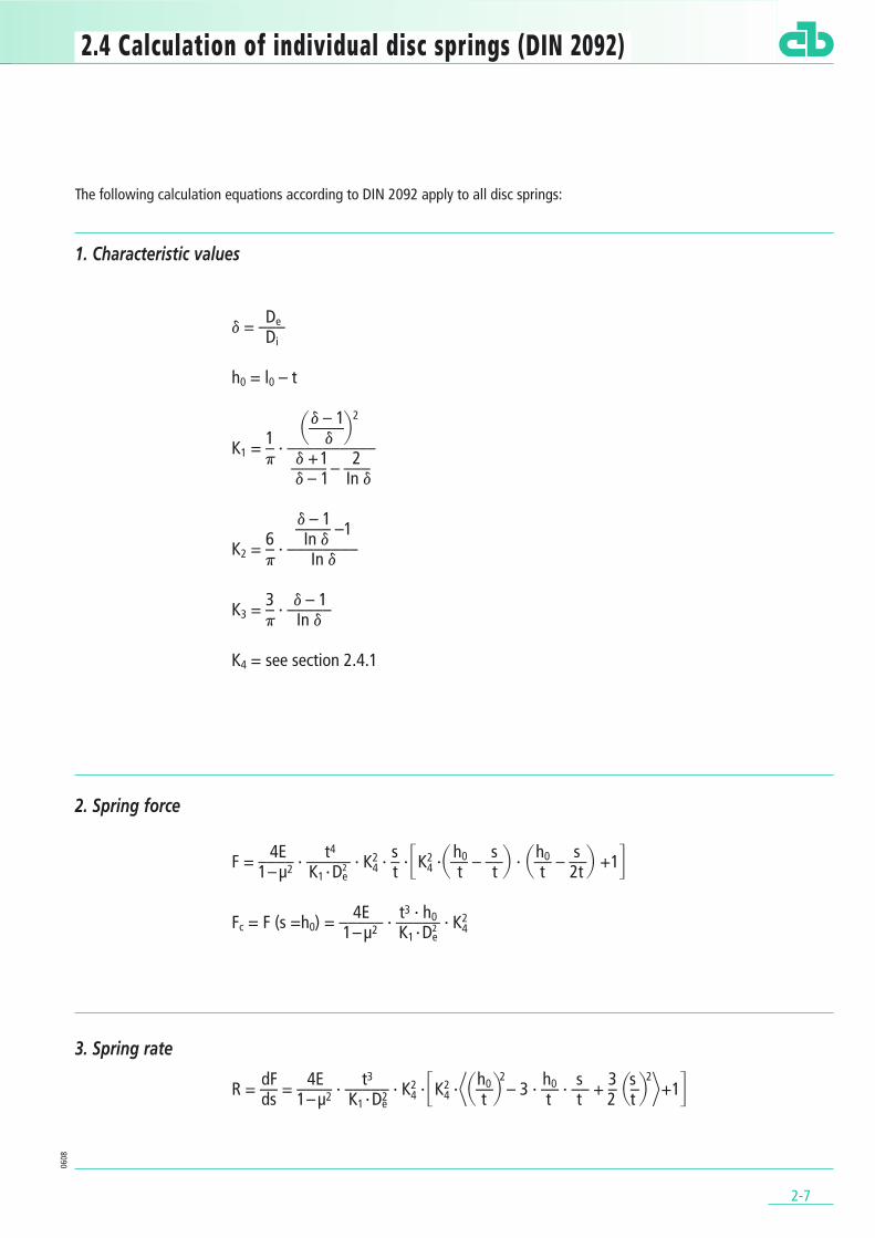
1. Characteristic values
2. Spring force
3. Spring rate
Ded = –––Di
h0 = l0 – t
d – 1 2$––––%1 d K1 = – · ––––––––––p d +1 2–––– – –––
d – 1 In d
d – 1–––– –16 In d K2 = – · ––––––––p In d
3 d – 1K3 = – · –––––p In d
K4 = see section 2.4.1
4E t4 s h0 s h0 sF = –––– · ––––– · K24 · – ·TK2
4 ·$–– – ––% · $–– – ––% +1Y1– µ2 K1 · D2e t t t t 2t
4E t3 · h0 Fc = F (s =h0) = ––––– · ––––– · K241– µ2 K1 · D2
e
dF 4E t3 h02 h0 s 3 s 2
R = –– = –––– · ––––– · K24 ·TK2
4 ·D$––% – 3 · –– · –– + – $–% F+1Yds 1– µ2 K1 · D2e t t t 2 t
The following calculation equations according to DIN 2092 apply to all disc springs:

4. Spring work
5. Calculated stresses
2-8
0608
s 2E t5 s 2 ho s 2W = ∫ F · ds = –––– · ––––– · K24 ·$–% ·TK2
4 ·$–– – ––% + 1Y0 1– µ2 K1 · D2
e t t 2t
4E t2 s 3 jOM = – –––– · ––––– · K4 · –– · –– 1– µ2 K1 · D2
e t p
4E t2 s h0 s jI = – –––– · ––––– · K4 · –– · TK4 · K2 $–– – ––% + K3Y1– µ2 K1 · D2
e t t 2t
4E t2 s h0 s jII = – –––– · ––––– · K4 · –– · TK4 · K2 $–– – ––% – K3Y1– µ2 K1 · D2
e t t 2t
4E t2 1 s h0 s jIII = – –––– · ––––– · K4 · –– · –– ·TK4 · (K2 –2K3) ·$–– – ––% – K3Y1– µ2 K1 · D2
e d t t 2t
4E t2 1 s h0 s jIV = – –––– · ––––– · K4 · –– · –– ·TK4 · (K2 –2K3) ·$–– – ––% + K3Y1– µ2 K1 · D2
e d t t 2t
For dimensions in compliance with DIN 2093 andfor steel grades with E = 206 000 N/mm2 and µ = 0.3, the calculated spring characteristics are wellin agreement with measurements.
For materials with µ deviating from 0.3, the value0.91 should be retained for 1 – µ2, in order to ensurea good level of agreement.
The CB calculation program is available as an aidto the calculation of disc springs (see Chapter2.14.2). This is provided on the attached CD ROMor can be downloaded from the Internet(www.christianbauer.com).
Positive stress values are tensile stresses, negative stress values are compressive stresses.

.2.4.1 Different types of disc springs.
2-9
0608
2.4.1.1 Disc springs without contact surfaces
For disc springs without contact surfaces, thecoefficient K4 assumes the value 1.
2.4.1.2 Disc springs with contact surfacesand reduced material thickness t’
The increase in force due to the contact surfacewhich results from a reduced lever arm length forforce application is compensated by reducing thematerial thickness of the disc springs from t to t’in such a way that the same spring force is obtainedwith a spring deflection s = 0.75 h0 as with theequivalent disc spring with no contact surfaces.
The reduction in thickness amounts to:
Coefficient K4:
with a = t’ · (l0 – 4t’ + 3t) · (5l0 – 8t’ + 3t)b = 32 (t’)3
c = – t · [5 (l0 – t)2 + 32t2]
For all calculation equations, this involves thefollowing substitutions:
t is replaced by t’h0 is replaced by h’0 = l0 - t’
Series A B Ct’/ t ≈ 0.94 ≈ 0.94 ≈ 0.96
Table 3
2.4.1.3 Disc springs with contact surfacesto the CB works standard
These disc springs conforming to the CB worksstandard are configured with contact surfaces innominal thickness (t = t’). The contact surfaces aredesigned so that for a spring deflection s = 0,75 h0 a 15 % higher spring force is obtainedthan with the equivalent disc spring with no contactsurfaces. Due to their contact surfaces, we assignthese springs to group 3.
Coefficient K4:
with a = 20 (l0 – t)2
b = 128 t2
c = – 1.15 (a + b)
2.4.1.4 Non-standard disc springswith contact surfaces (t = t’)
In the case of non-standard disc springs withcontact surfaces, the coefficient K4 must beselected in such a way that a contact surface witha technically sensible width is obtained. In theoverwhelming majority of this type of disc spring,the coefficient K4 lies in the range of 1.05 to 1.15.
2.4.1.5 Slotted disc springs
An approximated calculation of slotted disc springsis provided under chapter 2.10.4.
– b + klb2l–ll4laclK24 = –––––––––––––2a
– b + klb2l–ll4laclK24 = –––––––––––––2a
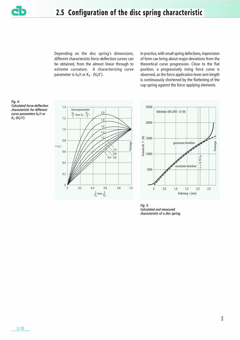
Depending on the disc spring’s dimensions,different characteristic force-deflection curves canbe obtained, from the almost linear through toextreme curvature. A characterizing curveparameter is h0/t or K4 · (h’0/t’).
In practice, with small spring defections, imprecisionof form can bring about major deviations from thetheoretical curve progression. Close to the flatposition, a progressively rising force curve isobserved, as the force application lever arm lengthis continuously shortened by the flattening of thecup spring against the force applying elements.
.2.5 Configuration of the disc spring characteristic.
2-10
0608
Fig. 4: Calculated force-deflectioncharacteristic for differentcurve parameters h0/t orK4 · (h’0 / t’).
Fig. 5: Calculated and measuredcharacteristic of a disc spring.

For special applications, non-standard disc springscan be designed in which the material loads arechosen with a view to preventing damage to thespring even in the event of spring deflection beyondthe flattened position. This option is of interest whengreater spring deflection is required in the flat orfalling area of the spring characteristic.
2-11
0608
Fig. 6: Calculated force / deflectioncharacteristics depending onh0/t or K4 · (h’0 / t’).
In this case, suitable force applying elements suchas the slightly conically shaped compressingsurface illustrated in the example, must be used.Detailed attention should be paid to finding asuitable execution of this type of design, whereapplicable in consultation with our advisory team.
2.5.1 Breakdown of disc springs into series A, B and C to DIN 2093
For each combination of diameters listed in thestandard, three different disc spring series exist withthe following characteristics:
Disc springs to series A, B and C are markedaccordingly in the tables (chapter 3).
F
F
Fig. 7: Conical force applyingelements for spring deflectionbeyond the flattenedposition.
Series A B CDe/t ≈ 18 ≈ 28 ≈ 40
h0/t / K4 · h0’/t’ ≈ 0.4 ≈ 0.75 ≈ 1,3 Characteristic shape approximately moderately highly
linear degressive degressiveSpring force high medium low
Table 4

.2.6 Disc spring stacks.
2-12
0608
The application range of individual disc springs canbe extended to cover higher forces and/or greaterdeflection by stacking.
For i alternating disc spring stacks, the followingapplies:
For n parallel disc spring stacks, the followingapplies:
In the case of disc springs with reduced materialthickness, t must be replaced by t’.
Fig. 8: Disc springs stacked inalternating or seriesformation.
Fig. 9: Disc springs stacked in parallelor nested formation.
Fges = F
Sges = i · s
L0 = i · l0
Fges = n · F
Sges = s
L0 = l0 + (n–1) · t
For i disc spring stacks in series made up of banksof n parallel nested disc springs, the followingapplies:
In the case of disc springs with reduced materialthickness, t must be replaced by t’. In the case ofdisc spring stacks made up of banks of group 2 discsprings (individual springs nested in parallelformation), to precisely determine the overallheight, we recommend consulting our advisoryteam.
In the above equations and the characteristicsprovided in the following (Figs. 11 to 14), theinfluence of friction has not been taken into account(see Chapter 2.9). For i > 1, with increasingdegressivity of the force-deflection characteristic theoverall deflection sges may be expected to becomeincreasingly unevenly distributed over the individualdisc springs or banks of disc springs. This is due tothe force differences from one disc spring to thenext, and to the influence of friction in the discspring stack. The force differences exert aparticularly marked influence in the case of discsprings with h0/t > 1.3 or K4 · (h’0/t’) > 1.3 . It istherefore not advisable to use this type of disc springfor the formation of stacks.
Fig. 10: Parallel banks of disc springs arranged in series.
Fges = n · F
Sges = i · s
L0 = i · [l0 + (n–1) · t]

2-13
0608
2.6.1 Schematic force-deflection char-acteristics of disc spring stacks
Fig. 11: Characteristic force-deflection curve of an individualdisc spring.
Fig. 12: Characteristic force-deflection curve of a disc spring stackmade up of four individual disc springs arranged inseries.
Fig. 13: Characteristic force-deflection curve if a disc spring stackcomprising one bank of disc springs arranged in parallel.
Fig. 14: Characteristic force-deflection curve of a discspring stack comprisingfour banks of disc springsarranged in series, eachmade up of two parallel ornested disc springs.
For the disc spring stack arrangements illustratedin Figs. 12 to 14, on principle disc springs withdifferent characteristics (see chapter 2.5) can beused. However, the specified limitations must betaken into account.
2.6.2 Progressive force-deflectioncharacteristic
As disc springs which can be used for stacking havea linear to degressive force-deflection characteristic(see chapter 2.5), special measures must beundertaken to achieve a progressively rising forcecharacteristic in a spring stack.
All the possible solutions illustrated here workaccording to the same principle. A disc spring stackis split into a number of partial stacks. The partialstacks are switched in the force flow in series. Byintroducing stops, it is possible to achieve an effectwhereby when certain required spring forces areexceeded, individual areas of the spring unit areblocked, while the remaining sections continue towork at the higher spring rate assigned to them.

2-14
0608
2.6.2.1 Disc spring stack comprising discsprings with different maximumspring force
When spring force Fx is reached, the disc springsreach their flattened state in area x, and then exertno further influence on continued spring deflection.An analogous effect occurs for the disc springs inthe area y when force Fy is reached.
2.6.2.2 Disc spring stack comprisingbanks of differently stacked discsprings
Fig. 16: Progressive characteristic force-deflection curve achievedby combining differently stacked disc springs.
A different load capability of the part areas isachieved here by varying the number of parallelstacked springs in the different banks.
Fig. 15: Progressive characteristicforce-deflection curveachieved by combining discsprings with differentmaximum spring force

2-15
0608
2.6.2.3 Disc spring stack with stops ofdifferent thicknesses
Fig. 17: Progressive force-deflection characteristic using stops of different thicknesses.
Using stops of different thicknesses, certain areasof the spring stack are successively excluded undera rising load from further deflection.
A general point to note here is that the anticipatedservice life of the entire stack arrangement isdetermined by the condition of the partial areaexposed to the highest stress.
2-16
0608
.2.7 Mounting guidelines for CB disc spring stacks.
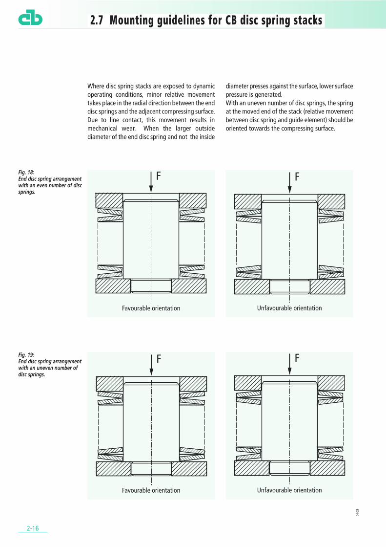
Where disc spring stacks are exposed to dynamicoperating conditions, minor relative movementtakes place in the radial direction between the enddisc springs and the adjacent compressing surface.Due to line contact, this movement results inmechanical wear. When the larger outsidediameter of the end disc spring and not the inside
diameter presses against the surface, lower surfacepressure is generated. With an uneven number of disc springs, the springat the moved end of the stack (relative movementbetween disc spring and guide element) should beoriented towards the compressing surface.
Favourable orientation Unfavourable orientation
Favourable orientation Unfavourable orientation
Fig. 18: End disc spring arrangementwith an even number of discsprings.
Fig. 19: End disc spring arrangementwith an uneven number ofdisc springs.
2-17
0608
2.7.1 Lubrication
Adequate lubrication exerts a decisive influence onguidance properties, friction and wear, andconsequently also on the service life of disc springs.Depending on the application, oil baths, grease,pastes with molybdenum sulphide additives or slidelacquer as well as other solid lubricants have provensuccessful.
2.7.2 Guide clearances (DIN 2093)
A suitable degree of clearance must be providedfor between the guiding elements and the discsprings. Internal guidance by means of a guide boltis preferred. External guidance can also be providedin the form of a guide sleeve.
2.7.3 Properties of guides and compressing surfaces
2.7.3.1 Dynamic load
Case-hardened and ground parts have provenparticularly successful. The surface hardness shouldbe at least 55 HRC, the case depth should not bebelow 0.8 mm. Other surface hardening techniquesare also possible, provided they provide sufficienthardened depth and strength of the base material.
2.7.3.2 Static load
Here, tempered parts, and for purely staticapplications frequently also untempered parts, aresufficient.
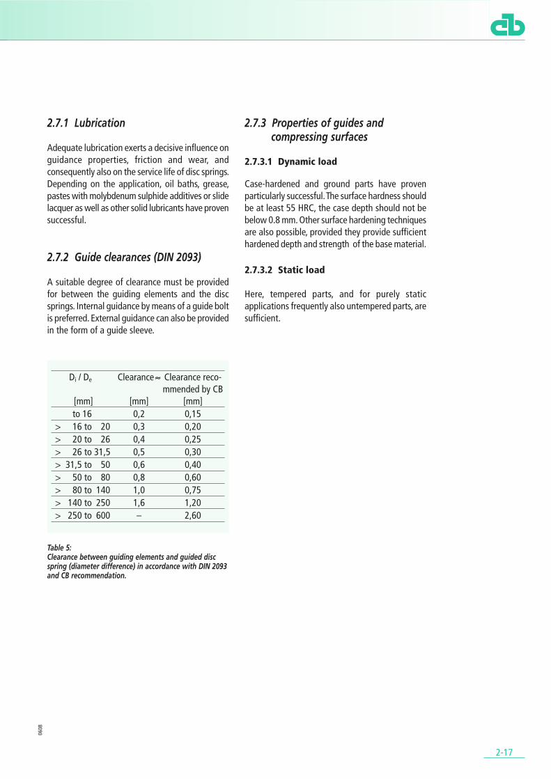
Di / De Clearance ≈ Clearance reco-mmended by CB
[mm] [mm] [mm] to 16 0,2 0,15
> 16 to 20 0,3 0,20> 20 to 26 0,4 0,25> 26 to 31,5 0,5 0,30> 31,5 to 50 0,6 0,40> 50 to 80 0,8 0,60> 80 to 140 1,0 0,75> 140 to 250 1,6 1,20> 250 to 600 – 2,60
Table 5: Clearance between guiding elements and guided discspring (diameter difference) in accordance with DIN 2093and CB recommendation.

.2.8 Admissible stress levels (DIN 2093).
2-18
2.8.1 Static stress
In the case of disc springs made of spring steel (DINEN 10 132-4), stress jOM in a flattened conditionshould not exceed the tensile strength (appr. 1 600 N/mm2) of the material. In case of higherlevels of stress, correspondingly high deflection maybe expected with a minor degree of directresetting. At the least, higher relaxation must beexpected than indicated under point 2.8.3. Minimal load cycles (up to around 5000) may beviewed in practice as static application.
2.8.2 Dynamic stress
2.8.2.1 Minimum pre-stress
By exceeding the yield limit during the settingprocess at cross-section point I of the disc spring,residual tensile strength can be generated. Undercyclical stress conditions, this can result in cracking.It is possible to counteract the influence ofresidual tensile strength by providing sufficient pre-stress in the disc springs. The minimum pre-stressstroke should be somewhere between s = 0.15 h0
and 0.20 h0. Depending on the stress level of thedisc springs, a greater pretension deflection may benecessary, or a smaller deflection may be sufficient.
2.8.2.2 Stress in the work range
When subjected to vibrating stress, the response ofa disc spring is determined by the tensile stressoccurring on the underneath of the spring. Thenumber of load cycles to fracture results from theminimum stress limit ju, assigned to the minimumdeflection and the upper stress limit jo, assignedto the maximum spring deflection. Whether thestress levels occurring at cross-section point II orcross-section point III (see Figs. 2 and 3) are decisivedepends on the dimensioning of the disc springs.The critical point can be deducted from thefollowing diagram. In the overlapping range, it isadvisable to calculate the stresses ju and jo bothfor point II and point III.
Fig. 20: Critical cross-section points depending on v d = De /Di andh0/t or K4 · (h’0 / t’).
2.8.2.3 Endurance and fatigue strength diagrams
The expected service life depending on ju and jo
in accordance with DIN 2093 may be deduced fromthe following diagrams. The service life informationcorresponds to the breakdown of disc springsaccording to groups is 1, 2 and 3.These diagrams were drawn up on the basis oflaboratory tests, taking a survival probability of 99%as a basis. Testing took place on individual discsprings and disc spring stacks comprising amaximum of 10 individually stacked disc springs.The guidance conditions corresponded to thosedescribed in chapter 2.7. The tests were performedat room temperature. There were no chemicalinfluences. The tested parts were free of damage.In case of deviating operating conditions, such asuneven stress application or with multiple stacking,and also for longer disc spring stacks (chapter 2.6),a reduction of the anticipated service life may beassumed. In the case of stacks comprising discsprings with a highly degressive characteristic (e.g.series C), due to scatter in some cases it may happenthat the overall deflection is unevenly distributedover the individual springs. This effect is exacerbatedby the influence of friction. In such cases, a shorterservice life may be expected than that indicated bythe diagrams.
0608

Fig. 21: Endurance and fatigue strength diagram for disc springswith t < 1.25 mm.
Fig. 22: Endurance and fatigue strength diagram for disc springswith 1.25 mm ≤ t ≤ 6 mm.
2-19
0608
* K. H. Hertzer: On thefatigue strength andsetting of disc springsIMF Research Report No. 27, Dissertation THBraunschweig 1959.
Fig. 24: Disc spring deflectionbehaviour in a stack inaccordance with Hertzer * (Disc springs 34 x 12.3 x 1.0;l0 = 2.25 mm, individuallystacked i = 10, 20 / 30; Pre-tension 0.1 mm and settravel 0.5 mm per discspring).
Fig. 23: Endurance and fatiguestrength diagram for discsprings with 6 mm < t ≤ 14 mm.

2-20
2.8.3 Prestressing disc springs
Disc springs are pre-stressed after the heattreatment stage. During this process, depending ontheir degree of stress, parts lose height. The discspring prestressing process must be performed insuch a way that after exposure to load at doublethe test force F (s = 0.75 h0) the admissible springforce deviations specified in chapter 2.11.1 areadhered to (cf. DIN 2093).
By pre-stressing, it is possible to generate a residualstress in the disc spring which counteracts thestresses applied later under load. Compressiveresidual stress on the underneath of the spring,particularly, has a beneficial effect on service life,as this is accompanied by a drop in actual stresslevels.
As the pre-stressing process is only a brief one, afterlong periods subjected to load, a subsequent post-stressing condition can occur. This is manifested inthe form of reduced spring force if the spring iscompressed to a constant length over time(relaxation) or a reduction of overall height l0 underconstant load (creep).
Reference values for relaxation are indicated in thefollowing diagrams. In each case, the loss of forceDF relative to the original spring force F is shownas a function of stress jOM.
Fig. 25: Admissible relaxation for disc springs made of C steels (DIN EN 10 132-4).
Fig. 26: Admissible relaxation for disc springs made of chromeand chrome-vanadium alloyed stainless steel grades to DIN EN 10 132-4 and DIN 17 221.
0608

2-21
2.8.4 Shot peening
By shot peening, it is possible to improve thedynamic loading capacity of disc springs throughthe creation of compressive residual stresses at theedge of the workpiece. This effect serves tocounteract even the highest tensile stresses whichare decisive to spring service life. In particular wherehigh component loads are involved, shot peeningmakes economic sense as a measure to increaseservice life. However, it does require a precisecoordination process relative to workpiecedimensions and material properties.
However, shot peening does result in increasedstressing of disc springs, and is accordingly notadvisable for static applications. We wouldrecommend consulting our advisory team. Otherthan this, shot peening does not otherwise improvethe properties of disc springs, which are in any caselifetime-proof without shot peening.
Fig. 27 illustrates an example of the influence ofshot peening on the fatigue of disc springs in stacksi=10, n=1. At the load level applicable here, asignificantly enhanced service life is achieved.
0608
* Partial result from AVIFproject A 115, Institut fürWerkstoffkunde, TUDarmstadt.
Fig. 27: Influence of shot peeningtreatment on the servicelife of bainiticallyhardened disc springs(indication of number ofload cycles until firstfracture of a spring in thestack*).
.2.9 The influence of friction.
2-22
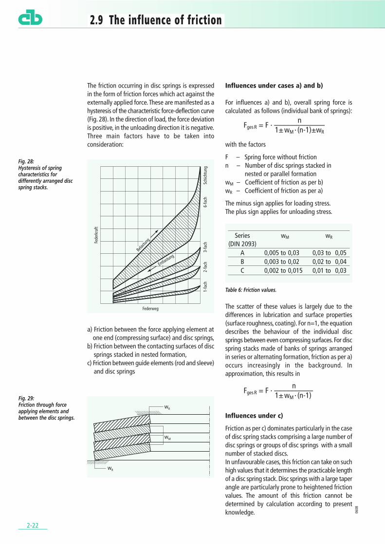
The friction occurring in disc springs is expressedin the form of friction forces which act against theexternally applied force. These are manifested as ahysteresis of the characteristic force-deflection curve(Fig. 28). In the direction of load, the force deviationis positive, in the unloading direction it is negative.Three main factors have to be taken intoconsideration:
a) Friction between the force applying element atone end (compressing surface) and disc springs,
b) Friction between the contacting surfaces of discsprings stacked in nested formation,
c) Friction between guide elements (rod and sleeve)and disc springs
Influences under cases a) and b)
For influences a) and b), overall spring force iscalculated as follows (individual bank of springs):
with the factors
F – Spring force without frictionn – Number of disc springs stacked in
nested or parallel formationwM – Coefficient of friction as per b)wR – Coefficient of friction as per a)
The minus sign applies for loading stress.The plus sign applies for unloading stress.
Table 6: Friction values.
The scatter of these values is largely due to thedifferences in lubrication and surface properties(surface roughness, coating). For n=1, the equationdescribes the behaviour of the individual discsprings between even compressing surfaces. For discspring stacks made of banks of springs arrangedin series or alternating formation, friction as per a)occurs increasingly in the background. Inapproximation, this results in
Influences under c)
Friction as per c) dominates particularly in the caseof disc spring stacks comprising a large number ofdisc springs or groups of disc springs with a smallnumber of stacked discs. In unfavourable cases, this friction can take on suchhigh values that it determines the practicable lengthof a disc spring stack. Disc springs with a large taperangle are particularly prone to heightened frictionvalues. The amount of this friction cannot bedetermined by calculation according to presentknowledge. 06
08
wM
wR
wR
Fig. 29: Friction through forceapplying elements andbetween the disc springs.
nFges R = F · –––––––––––––
1± wM · (n-1)±wR
nFges R = F · ––––––––––
1± wM · (n-1)
Series wM wR
(DIN 2093) A 0,005 to 0,03 0,03 to 0,05B 0,003 to 0,02 0,02 to 0,04C 0,002 to 0,015 0,01 to 0,03
Fig. 28: Hysteresis of springcharacteristics fordifferently arranged discspring stacks.

.2.10 Special disc spring configurations and applications.
2-23
2.10.1 Self-centering disc springs
Problems arising from the friction between theguide element and disc springs have sparked offconsiderations as to the possibility of workingwithout guide elements. A series of solutions arebeing developed in which friction becomes eithernegligibly small or at least relatively minor andreproducible.
2.10.1.1 Centering using cylindrical shoulders at the inside and outside diameter
Fig. 30: Disc spring stack with cylindrical shoulders.
This method would be particularly beneficial in thecase of disc springs which are machined on all sides.
2.10.1.2 Intermediate centering rings
Fig. 31: Disc spring stack with intermediate rings.
Disc springs can be held in position relative to eachother by intermediate rings with T-shaped cross-section.
2.10.1.3 Ball or wire ring centering
Disc springs can be provided with a ring-shapedgroove in the area of the lower outside diameteror the upper inside diameter. This groove can beused to accommodate either a large number of tinyballs or wire ring sections.
2.10.2 Application with bilateralspring support
Using disc springs, it is possible to hold a bodyelastically between two surfaces (Fig. 33). For this,the object (Fig. 33) is gripped between two discsprings with (a) or without (b) pre-stress. Disc springstacks can also be used here. In case (b) using disc springs without pre-stressing,the body experiences the simple restoring force ofa disc spring in case of axial deflection. In the caseof the pre-stressed springs (a), the restoring forceis generated by the difference between the forcesof the two springs. Depending on the level of pre-stress, the spring rate is always higher here thanthat of the individual spring.
0608
Fig. 32: Disc spring stack with ball or wire ringcentering.
Fig. 33: Body gripped betweentwo disc springs.
2-24
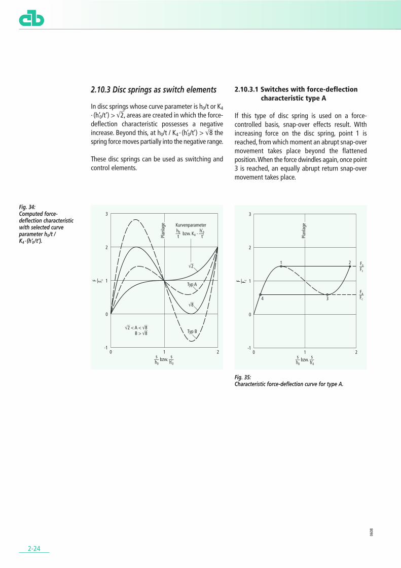
2.10.3 Disc springs as switch elements
In disc springs whose curve parameter is h0/t or K4
· (h’0/t’) > M2, areas are created in which the force-deflection characteristic possesses a negativeincrease. Beyond this, at h0/t / K4 · (h’0/t’) > M8 thespring force moves partially into the negative range.
These disc springs can be used as switching andcontrol elements.
2.10.3.1 Switches with force-deflection characteristic type A
If this type of disc spring is used on a force-controlled basis, snap-over effects result. WIthincreasing force on the disc spring, point 1 isreached, from which moment an abrupt snap-overmovement takes place beyond the flattenedposition. When the force dwindles again, once point3 is reached, an equally abrupt return snap-overmovement takes place.
Fig. 35: Characteristic force-deflection curve for type A.
0608
Fig. 34: Computed force-deflection characteristicwith selected curveparameter h0/t / K4 · (h’0 /t’).
2-25
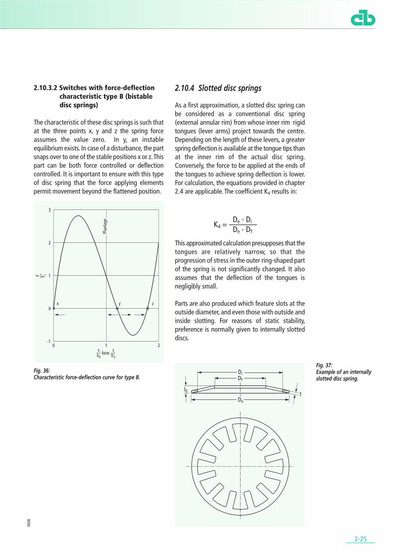
2.10.3.2 Switches with force-deflection characteristic type B (bistable disc springs)
The characteristic of these disc springs is such thatat the three points x, y and z the spring forceassumes the value zero. In y, an instableequilibrium exists. In case of a disturbance, the partsnaps over to one of the stable positions x or z. Thispart can be both force controlled or deflectioncontrolled. It is important to ensure with this typeof disc spring that the force applying elementspermit movement beyond the flattened position.
Fig. 36: Characteristic force-deflection curve for type B.
2.10.4 Slotted disc springs
As a first approximation, a slotted disc spring canbe considered as a conventional disc spring(external annular rim) from whose inner rim rigidtongues (lever arms) project towards the centre.Depending on the length of these levers, a greaterspring deflection is available at the tongue tips thanat the inner rim of the actual disc spring.Conversely, the force to be applied at the ends ofthe tongues to achieve spring deflection is lower.For calculation, the equations provided in chapter2.4 are applicable. The coefficient K4 results in:
This approximated calculation presupposes that thetongues are relatively narrow, so that theprogression of stress in the outer ring-shaped partof the spring is not significantly changed. It alsoassumes that the deflection of the tongues isnegligibly small.
Parts are also produced which feature slots at theoutside diameter, and even those with outside andinside slotting. For reasons of static stability,preference is normally given to internally slotteddiscs.
0608
Fig. 37: Example of an internallyslotted disc spring.
De - DiK4 = –––––––De - Df

.2.11 Limit deviations (DIN 2093).
2-26
2.11.1 Spring force limit deviations
2.11.1.1 Individual disc springs
The static spring force F is determined in accordancewith DIN 2093 at a defined test length Iprüf and notat a given deflection s, which as a rule wouldproduce flawed results.
The test length lprüf is calculated from the overallheight I0 and the calculation variable h0 as follows
In the case of disc springs with contact surfaces, therated thickness t is assumed and not the reducedthickness t’. Measurement must be performed inthe direction of load. The compression surfacesacting on the spring must be hardened, ground andpolished. In addition, a suitable lubricant must beused.
The limit deviations of the spring force at lprüf forcustomary applications are as follows:
In order to adhere to the spring force, in some casesit may be necessary to drop slightly below the limitdeviations for the overall height l0.
2.11.1.2 Spring stack
This test is performed on disc spring stackscomprising ten individually stacked disc springs. Thespring force measured on unloading may not fallbelow a minimum percentage value of the springforce determined on the application of load(Table 8). The test points are positioned at testlength
Before testing, the stack must be compressed attwice the rated force F (s = 0.75 h0) of the individualdisc springs. The compression surfaces at the endsof the disc spring demonstrate the same propertiesas for the force test performed on individual discsprings. The parts are guided by a rod as describedunder chapter 2.7.3. Here, too, care must be takento provide sufficient lubrication.
Fig. 38: Test points on the characteristic loading and unloadingcurve of a disc spring stack.
Table 8: Minimum percentage value of unloading spring force.
The force values determined in this way cannot berelated to the values measured for the individualdisc springs.
0608
Iprüf = I0 – 0,75 h0 with h0 = l0 – t
Lprüf = L0 – 7,5 h0
Table 7: Limit deviations of springforce at lprüf.
LimitGroup t deviations
spring force F[mm] [%]
1 < 1,25+25,0– 7,5
1,25 to 3,0+15,0
2– 7,5
> 3,0 to 6,0+10,0 – 5,0
3 > 6,0 to 14,0 ± 5,0
SeriesGroup A B C
[%] min. [%] min. [%] min.1 90,0 90,0 85,02 92,5 92,5 87,53 95,0 95,0 90,0
2-27
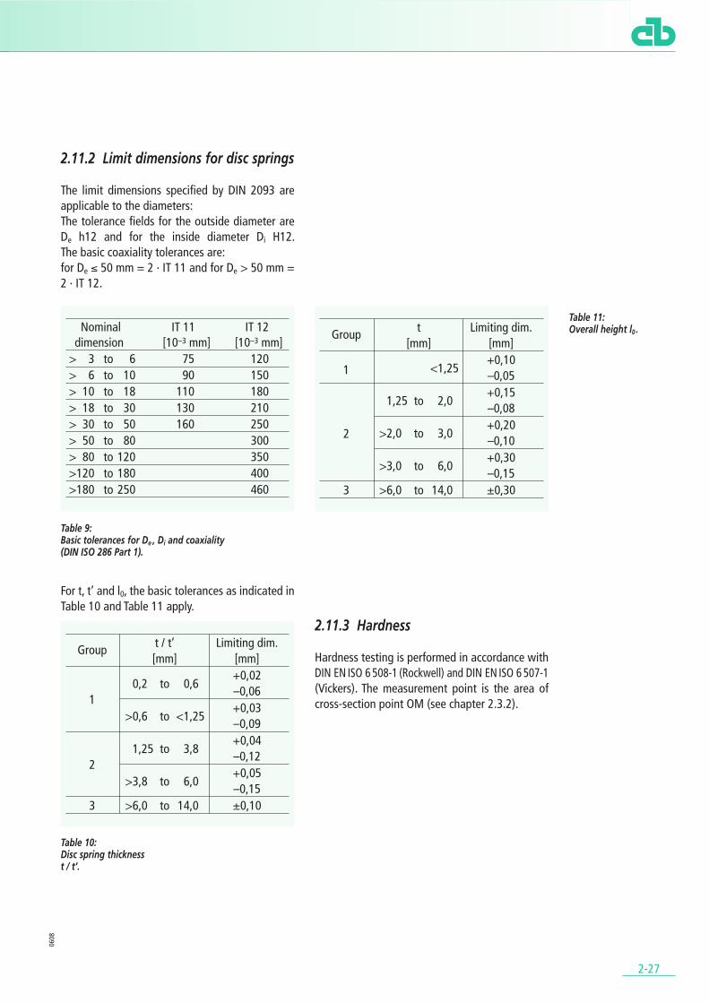
2.11.2 Limit dimensions for disc springs
The limit dimensions specified by DIN 2093 areapplicable to the diameters:The tolerance fields for the outside diameter are De h12 and for the inside diameter Di H12. The basic coaxiality tolerances are:for De ≤ 50 mm = 2 · IT 11 and for De > 50 mm =2 · IT 12.
Table 9: Basic tolerances for De , Di and coaxiality (DIN ISO 286 Part 1).
For t, t’ and l0, the basic tolerances as indicated in Table 10 and Table 11 apply.
2.11.3 Hardness
Hardness testing is performed in accordance with DIN EN ISO 6 508-1 (Rockwell) and DIN EN ISO 6 507-1 (Vickers). The measurement point is the area ofcross-section point OM (see chapter 2.3.2).
0608
Table 10: Disc spring thickness t / t’.
Table 11: Overall height l0 .Nominal IT 11 IT 12
dimension [10–3 mm] [10–3 mm] > 3 to 6 75 120> 6 to 10 90 150> 10 to 18 110 180> 18 to 30 130 210> 30 to 50 160 250> 50 to 80 300> 80 to 120 350>120 to 180 400>180 to 250 460
Group t / t’ Limiting dim.[mm] [mm]
0,2 to 0,6+0,02
1–0,06
>0,6 to <1,25+0,03 –0,09
1,25 to 3,8+0,04
2–0,12
>3,8 to 6,0+0,05 –0,15
3 >6,0 to 14,0 ±0,10
Group t Limiting dim.[mm] [mm]
<1,25+0,10
1 –0,05
1,25 to 2,0+0,15 –0,08
>2,0 to 3,0+0,20
2 –0,10
>3,0 to 6,0+0,30 –0,15
3 >6,0 to 14,0 ±0,30

.2.12 Materials for CB disc springs.
2-28
2.12.1 General
The materials listed in table 13 (page 2-32) are usedat CB for the manufacture of disc springs. The rawmaterials used, depending on the spring size andpiece numbers required, include strip, sheet orforged blanks. Strain-hardened strip and sheetmaterials are sometimes used.
A breakdown of materials according to availabilityhas been dispensed with, as even the procurementof a commonly used material, for example inaccordance with DIN EN 10 132-4 or DIN 17 221, ina thickness not kept in stock or in small quantitiescan cause considerable difficulty or be impossible.
In the case of thermally stable and corrosion proofmaterials to customer specification, extendeddelivery periods may be expected. We wouldtherefore recommend reviewing the procurementpossibilities for a particular spring as early as thedevelopment or planning phase. Table 13 (page 2-32) lists the smelting analysis for the compositionof materials within the admissible scatter range.When performing piece analyses, the admissibledeviations in accordance with the valid standard(EN or DIN) must be taken into consideration.Accompanying elements which are not listed areadmissible provided the specified values for themechanical characteristics and durability areadhered to and the usability of the springs is notimpaired.
Table 14 (page 2-33) lists material characteristicvalues applicable for materials in a tempered, strain-hardened and/or age-hardened condition.Depending on the thickness or type of rawmaterial, tensile strength values can be attainedhere which lie within the prescribed scatter range.The values provided are guidelines, and deviationsto them are possible in both directions in springs.In normal cases, the deviation within any oneproduction batch lies within only 50% of thespecified scatter range.
With regard to the listed maximum applicationtemperatures, it is important to bear in mind thatthe relaxation of the springs depends on theoccurring stresses and the period of time the springsare deployed at temperature. It should also be notedthat with increasing temperature, the modulus ofelasticity (Fig. 39) of the material and the strength(Fig. 40) both diminish. In some cases, corrosion-resistant and thermally stable materials have lowerstrength values at room temperature than springsteel. If the same spring deflection and the samespring force are required for a certain steel spring,then a recalculation will be necessary. In most cases,the lower strength necessitates a reduced overallheight (l0) of the disc spring.
0608
Fig. 39: Influence of temperatureon the modulus ofelasticity.
Fig. 40: Influence of temperature on the yield point.
2-29
2.12.2 Spring steels
C67S (1.1231), C75S (1.1248), 51CrV4 (1.8159)and 51CrMoV4 (1.7701) are stainless steel grades toDIN EN 10 132-4 / DIN 17 221 which are particularlysuited to the manufacture of spring-loadedcomponents of all types when in a temperedcondition. For disc springs to DIN 2093, thematerials C67S (1.1231) and C75S (1.1248) mayonly be used up to a spring thickness of t = 1.25 mm.
The materials 51CrV4 (1.8159) and 51CrMoV4(1.7701) are admissible for all DIN springs. The useof alloy additions produces an even microstructureformation over the entire cross section for greatermaterial thicknesses after tempering. In addition,the alloy components exert a positive influence onrelaxation behaviour.
As a rule, a bainite tempering treatment isperformed on springs made of these materials. Thishas a range of benefits to offer over hardening andage-hardening. Bainite tempering involvesquenching and keeping the springs in a hot bathafter austenitization, meaning that a transformationof the microstructure takes place in the bainitestage. This results in lower distortion and a lowerchange in the volume of the workpiece. The bainitemicrostructure is characterized by particularlygood tenacity. As an additional age-hardeningprocess is eliminated, less energy is used.
2.12.3 Thermally stable spring steels
48CrMoV6-7 (1.2323), 30WCrV17-2 (1.2567),X39CrMo17-1 (1.4122) and X22CrMoV12-1(1.4923).
Springs made of these materials are designed foruse at higher temperatures (see Table 14, page 2-33). Due to their chemical composition, they offersufficient thermal stability for the intendedtemperature range.
The materials 48CrMoV6-7 (1.2323) and30WCrV17-2 (1.2567) are not corrosion resistant.The materials X39CrMo17-1 (1.4122) andX22CrMoV12-1 (1.4923) demonstrate only veryconditional corrosion resistance despite theirchrome and molybdenum additives. This is due tothe fact that chrome carbide precipitation occursduring the necessary heat treatment stages ofhardening and age-hardening. In chrome-poorareas, the integral passive layer required for goodcorrosion resistance is missing. Where there is acombined requirement for corrosion resistance andthermal stability, amongst the steel grades thematerial X7CrNiAl17-7 (1.4568) provides a viableoption (chapter 2.12.4).
2.12.4 Non-rusting spring steels
X10CrNi18-8 (1.4310), X5CrNiMo17-12-2(1.4401) and X7CrNiAl17-7 (1.4568) are non-rusting spring steels in compliance withDIN EN 10 151 which are characterized by specialresistance to chemically aggressive substances.
Their spring power is generated as a result of strainhardening and/or heat treatment. Both typesX10CrNi18-8 (1.4310) and X5CrNiMo17-12-2(1.4401) attain their strength solely by strainhardening. For this reason, they are generally onlyused up to a thickness of 2 to 2.5 mm. Dependingon the degree of strain hardening, a markedbreakdown of straining hardening takes place fromaround 100 °C. These materials should accordinglynot be used at high temperatures.
0608

2-30
With the material X7CrNiAl17-7 (1.4568) up toa thickness of 2.5 mm (for larger quantities up to3.0 mm), alongside strain hardening, a simple heatstorage treatment at 480 °C is also performed,lending it thermal stability to permitting 350 °C.The increase in strength achieved by heat exposureoffers the benefit that to achieve the same endstrength, less strain hardening is required as forX10CrNi18-8 (1.4310) or X5CrNiMo17-12-2(1.4401). This positively affects the corrosioncharacteristics.
The material X7CrNiAl17-7 (1.4568) is processedin a solution annealed condition in thicknesses > 2.5 mm (3 mm). The required degree of strengthis then achieved by a dual heat exposure process(structure tempering). As the first exposure periodhas to take place at a temperature of 760 °C,chrome carbide precipitation takes place, primarilyat the grain boundaries, this substantially diminishesthe corrosion resistance of this material condition.Springs in a structure tempered condition shouldonly be used where specific demands are made onthermal stability. These springs should never bedegreased in an acidic medium.
When in a soft condition, the materials X10CrNi18-8 (1.4310) and X5CrNiMo17-12-2(1.4401) are hardly magnetizable. By means ofstrain hardening, X10CrNi18-8 (1.4310) becomesmagnetizable to a greater or lesser degree, whileX5CrNiMo17-12-2 (1.4401) remains almostunmagnetizable. X7CrNiAl17-7 (1.4568) is alreadyclearly magnetizable when soft. The magnetizationcapability is further increased by strain hardening.
2.12.5 Thermally stable specialmaterials with very good corrosion resistance.
NiCr19Fe19Nb5Mo3 (2.4668), NiCr15Fe7TiAl(2.4669) and NiCr20Co18Ti (2.4969) are nickel-based alloys. Duratherm 600 is a cobalt-basedalloy.
These are age-hardenable alloys whose strength isachieved by solid-solution hardening, the additionof highly diffusion-inhibiting elements and stableprecipitations. By strain hardening prior to age-hardening, even higher strength values as thoseindicated in Table 14 (page 2-33) can be achieved.Alongside their thermal stability and resistance toscale, these materials are characterized byoutstanding corrosion resistance. Due to the highchrome and nickel content, they are fully corrosionresistant in the outer area and resistant to manyaggressive media. As the corrosion properties of amaterial are dependent not only on the type ofattacking medium but also on outline conditionssuch as temperature, occurring material stress,ventilation etc., we recommend obtaining advicefrom us if there is a danger of corrosion. As indicatedin Table 14 (page 2-33), these materials can be usedclose to the absolute zero point. They are notmagnetizable up to the Curie temperature. If thereis a drop below the specified Curie temperature, thematerial becomes ferromagnetic.
0608
Material ≈ [°C] NiCr19Fe19Nb5Mo3 – 112(Inconel 718) NiCr15Fe7TiAl – 125 (Inconel X750) NiCr20Co18Ti – 112 (Nimonic 90) Duratherm 600 – 50
Table 12: Curie temperatures.

2-31
2.12.6 Non-magnetic and corrosion-resistant materials
CuBe1.7 (2.1245) and CuBe2 (2.1247) (DINEN 1654) are age-hardenable, low-alloy wroughtcopper alloys. Disc springs made of these materialsare generally manufactured from semi-hard strip orsheet and then undergo subsequent heat treatment,so-called “age-hardening” to lend them their endstrength. Copper beryllium, particularly, ischaracterized by a marked age-hardening effect,and accordingly achieves favourable strength andelasticity values. The materials can be used closeto the absolute zero point, are fully non-magneticin the specified temperature range and possessgood thermal and electrical conductivity. Thematerials offer good resistance to a variety ofchemically aggressive substances. Whenconfiguring a spring, the substantially lowermodulus of elasticity compared to spring steel mustbe taken into account.
As regards the use of CuBe materials, certainlimitations may have to be observed in view of theirtoxicity.
2.12.7 Non-magnetic light alloy with good corrosion resistance
TiAl6V4 (3.7165) is a wrought titanium alloy whichis used for preference in the aerospace industry. Witha density of 4.45 kg/dm3, it reaches only around halfthe weight of spring steel (7.85 kg/dm3). Due to itsnon-magnetic behaviour and good corrosionresistance to a large number of media, use of thismaterial is not restricted to the aerospace sector.For disc spring manufacture, sheet, strip or forgingscan be used. In an annealed, scale free condition,the material already reaches a tensile strength ofRm of at least 890 N/mm2 and a 0.2 yield point Rp0,2
of at least 820 N/mm2. As a result of age-hardening,the strength values listed in Table 14 are achieved.The modulus of elasticity is considerably lower thanthat of spring steel. This factor must be taken intoconsideration in the spring design. The materialthickness must be increased by around 22% toensure that the same spring force and deflectionare achieved with the same outside and insidediameter as for a spring with spring steel.
0608

Abbreviation Mater- Standard Chemical composition in % by weightial no. DIN C Si Mn P max. S max. Cr V Mo Ni
Quality and stainless steels
C67S 1.1231 EN 10 132-4 0,65...0,73 0,15...0,35 0,60...0,90 0,025 0,025 max. 0,40 – max. 0,10 max. 0,40
C75S 1.1248 EN 10 132-4 0,70...0,80 0,15...0,35 0,60...0,90 0,025 0,025 max. 0,40 – max. 0,10 max. 0,40
51CrV4 1.8159 EN 10 132-4 0,47...0,55 max. 0,40 0,70...1,10 0,025 0,025 0,90...1,20 0,10...0,25 max. 0,10 max. 0,40
51CrMoV4 1.7701 17 221 0,48...0,56 0,15...0,40 0,70...1,10 0,030 0,030 0,90...1,20 0,08...0,15 0,15...0,25 –
Thermally stable steels
48CrMoV6-7 1.2323 17 350 0,40...0,50 0,15...0,35 0,60...0,90 0,030 0,030 1,30...1,60 0,25...0,35 0,65...0,85 –
30WCrV17-2 1.2567 – 0,25...0,35 0,15...0,30 0,20...0,40 0,035 0,035 2,20...2,50 0,50...0,70 – W: 4,0...4,5
X39CrMo17-1 1.4122 EN 10 088-1 0,33...0,45 max. 1,00 max. 1,50 0,040 0,015 15,5...17,5 – 0,80...1,30 max. 1,00
X22CrMoV12-1 1.4923 EN 10 269 0,18...0,24 max. 0,50 0,40...0,90 0,025 0,015 11,0...12,5 0,25...0,35 0,80...1,20 0,30...0,80
Non-rusting steels
X7CrNiAl17-7 1.4568 EN 10 151 max. 0,09 max. 0,70 max. 1,00 0,040 0,015 16,0...18,0 Al: 0,70...1,50 – 6,50...7,80
X10CrNi18-8 1.4310 EN 10 151 0,05...0,15 max. 2,00 max. 2,00 0,045 0,015 16,0...19,0 N: max. 0,11 max. 0,80 6,00...9,50
X5CrNiMo17-12-2 1.4401 EN 10 151 max. 0,07 max. 1,00 max. 2,00 0,045 0,015 16,5...18,5 N: max. 0,11 2,00...2,50 10,0...13,0
2-32
0608
Nickel and cobalt alloys
Abbreviation Materi- Standard Chemical composition in % by weightial no. DIN C Si max. Mn max. P max. S max. Co Cr
NiCr19Fe19Nb5Mo3 (Inconel 718) 2.4668 EN 10 302* 0,02...0,08 0,35 0,35 0,015 0,015 max. 1,00 17,0...21,0
NiCr15Fe7TiAl (Inconel X750) 2.4669 EN 10 269 max. 0,08 0,50 1,00 0,020 0,015 max. 1,00 14,0...17,0
NiCr20Co18Ti (Nimonic 90) 2.496917 754
max. 0,13 1,00 1,00 – 0,015 15,0...21,0 18,0...21,059 745
Duratherm 600 – – – – – – – 40 12
Continuation (* Draft)
Abbreviation Mater- Chemical composition in % by weightial no. Ni Mo Cu max. Fe Nb Ti Al Others
NiCr19Fe19Nb5Mo3 (Inconel 718) 2.4668 50,0...55,0 2,80...3,30 0,20 Rest4,70...5,50
0,6...1,20 0,30...0,70B:
(Nb + Ta) 0,002...0,006
NiCr15Fe7TiAl (Inconel X750) 2.4669 ≥70 – 0,50 5,00...9,000,70...1,20
2,25...2,75 0,40...1,00(Nb + Ta)
NiCr20Co18Ti (Nimonic 90) 2.4969 Rest – 0,20 max. 1,50 – 2,00...3,00 1,00...2,00
Duratherm 600 – 26 – – Rest – – – Mo, W, Ti, Al
Copper alloys
Abbreviation Mater- Standard Chemical composition in % by weightial no. DIN Be Co Fe Ni Cu Others
CuBe1,7 2.1245 EN 1 654 1,60...1,80 max. 0,30 max. 0,20 max. 0,30 Resid. max. 0,50
CuBe2 2.1247 EN 1 654 1,80...2,10 max. 0,30 max. 0,20 max. 0,30 Resid. max. 0,50
Titanium alloys
Abbreviation Mater- Standard Chemical composition in % by weightial no. DIN Al Fe V Ti
TiAl6V4 3.7165 DIN 17 851 5,50...6,75 max. 0,30 3,50...4,50 Resid.
Table 13: Chemical composition of disc spring materials.

2-33
Abbreviation Mat- Standard Thickness Yield Tensile Modulus of elasticity in [kN/mm2] at Applicationerial DIN point strength temperatureno. min. [°C]
[mm] [N/mm2] [N/mm2] 20 100 200 300 400 500 600 700 800 [°C]
Quality and stainless steels
C67S 1.1231 EN 10 132-4 < 2,5 1000 1330...1780 206 – – – – – – – – -20...+ 60
C75S 1.1248 EN 10 132-4 < 4,5 1050 1330...1780 206 – – – – – – – – -20...+ 60
51CrV4 1.8159 EN 10 132-4 < 30 1100 1330...1780 206 202 196 – – – – – – -50...+100
51CrMoV4 1.7701 17 221 < 50 1100 1330...1780 206 202 196 – – – – – – -50...+100
Thermally stable steels
48CrMoV6-7 1.2323 17 350 < 50 1100 1330...1780 206 202 196 189 179 – – – – -60...+300
30WCrV17-2 1.2567 – < 30 1100 1300...1600 206 202 196 189 179 168 – – – -60...+400
X39CrMo17-1 1.4122 EN 10 088-1 < 20 1000 1200...1600 209 205 199 192 181 172 – – – -60...+400
X22CrMoV12-1 1.4923 EN 10 269 < 20 1000 1200...1600 206 202 196 189 179 168 – – – -60...+500
Non-rusting steels
X7CrNiAl17-7 1.4568 EN 10 151< 2,5 (3,0) 1150 1300...1700
200 195 185 175 165 – – – – -200...+350< 2,5...7,0 1000 1250...1600
X10CrNi18-8 1.4310 EN 10 151 < 2,0 960 1200...1600 190 185 – – – – – – – -200...+100
X5CrNiMo17-12-2 1.4401 EN 10 151 < 1,6 720 900...1500 185 180 – – – – – – – -200...+100
Nickel and cobalt alloys
NiCr19Fe19Nb5Mo32.4668 EN 10 302* < 100 1030 ≥ 1240 200 195 190 184 178 172 167 160 – -260...+700(Inconel 718)
NiCr15Fe7TiAl2.4669 EN 10 269
0,25...6,30 790 ≥ 1170214 207 198 190 179 170 158 – – -260...+600(Inconel X750) < 100 720 ≥ 1100
NiCr20Co18Ti2.4969
17 754< 100 700 ≥ 1100 206 201 195 189 181 175 167 160 151 -260...+800(Nimonic 90) 59 745
Duratherm 600 – –≤ 3 (1/2 hard) 1000 ≥ 1200
220 214 207 200 193 185 – – – -260...+500≤ 20 500 ≥ 850
(* Draft)
Copper alloys
CuBe1,7 2.1245 EN 1 654 < 20 1000 1170...1340 135 131 125 – – – – – – -260...+200
CuBe2 2.1247 EN 1 654 < 20 1120 1270...1450 135 131 125 – – – – – – -260...+200
Titanium alloy
TiAl6V4 3.716517 851 < 19 1000 ≥ 1100
114 110 105 98 93 – – – – -70...+35017 860 < 50 930 ≥ 1000
(Modulus of elasticity: guideline value dependent upon semi-finished product)
0608
Table 14: Characteristics of disc spring materials

2.13.1 General
Spring steels tend in general to be corrosive. As arule, a corrosion prevention coating only delays thedestructive effect. As the corrosion of steel is ahighly complex problem and depends upon a wholeseries of influencing variables, this description willnot attempt to enter into detail on the individualcorrosion problems. The surface protection measureslisted in table 15 (page 2-36) have provensuccessful in practice. They often represent acompromise between the ideal and the mosteconomical corrosion prevention. In the case ofmarked chemical attack, it is advisable to generallyexamine whether it makes sense to use a springmade of corrosion resistant materials, particularlywhen high failure and mounting costs are incurredin case of damage.
As the force is applied in disc springs over narrowcontact surfaces, the occurring surface pressurelevels are relatively high. Coated springs exposedto dynamic applications are subject to cracking andwear of the coating in these areas. In this case,crevice corrosion and local element formation inthese areas can no longer be prevented. If thecoating material is of a superior grade to the basematerial, as is the case for example with nickelcoatings, damage to the coating results inheightened corrosion of the base metal due to thehigh potential difference in the electrochemicalseries.
Galvanic surface coatings should not be used fordisc springs exposed to cyclical stress, as when usingcurrently known procedures for the separation ofmetal coatings made of aqueous solutions,hydrogen permeates the material, bringing with itthe possibility of a hydrogen-induced brittlefracture.
2.13.2 Commonly used coatingsfor CB disc springs
and CB fastener Bellevilles
The corrosion prevention method generally used atCB for disc springs made of low-alloy spring steelsis a zinc phosphate coating whose pores areclosed with a corrosion protection oil. In the caseof multiple coatings and applications wherephosphate abrasion could be a possible disturbingfactor, the bright parts are given only treatment withcorrosion protection oil for dispatch and forinternal storage. Wax and grease have provensuccessful on large springs for static applicationsalso for outdoor application under a protective roof.
Zinc coatings for steel parts have beensuccessfully used for decades. The corrosionprotecting effect is primarily due to the fact thatzinc is a lower grade metal than the material it isprotecting. In humid air, corrosion is generated onthe zinc surface (white rust). This process can beeffectively slowed down by chromatizing the zinccoating. The zinc has an anodic reaction in contactwith the steel substrate in the presence of anelectrolyte. During the process of corrosion, localelements form, whereby the zinc turns to a solutionand the steel substrate remains protected. Thismechanism works also in case of damaged areas(so-called remote protective action). The corrosiveprotection afforded by zinc is limited to the corrosivemedia atmosphere and water up to a maximumtemperature of 60 °C. Zinc is not resistant to acidicalkaline solutions of organic substances, and maynot be used in food applications as a corrosionprotecting agent.
Zinc-rich paint is used for large disc springs andsmaller piece numbers. A decisive factor in its anti-corrosion action is the binding agent used and thethickness of the coat.
.2.13 Corrosion prevention for CB disc springs.
2-34
0608
2-35
0608
The method most frequently used to galvanize CBdisc springs is that of ball plating. This methodinvolves first carefully cleaning the parts byimmersion (electroless) and then applying a thincopper coating. The parts are then agitatedtogether with zinc powder and glass balls ofdifferent sizes in a barrel with the addition of apromotor. After a certain period, the treatment isinterrupted, whereby 95 - 98% of the added zincis plated on the disc springs. The parts aresubsequently chromatized in chromate solution. Theeffectiveness of chromate coating diminishes attemperatures over 60 °C. If the process is expertlyperformed, only a minimal, negligibly small degreeof hydrogen embrittlement takes place on theworkpieces.
Dacromet 320 is a corrosion protection methoddeveloped in the USA and applied under licence bya variety of contract finishing firms. Dacromet is athin-layer coating based on zinc and aluminiumflakes which is applied to the workpiece with theaid of a chromate solution. A subsequent heattreatment at around 300 °C (curing) results in afirmly adhesive layer containing chrome (VI). A veryhigh level of corrosion protection is attained in saltspray testing. In addition, endurance temperatureresistance is 300 C. Hydrogen embrittlement ofworkpieces is excluded for normal Dacrometapplication.
Geomet 321 is a further development based onDacromet which is free of triavalent and hexavalentchrome and which complies with more recentenvironmental legislation. In salt spray mist testing,comparable corrosion resistance levels are achievedas with Dacromet. Endurance temperatureresistance and absence of hydrogen embrittlementare identical.
Polyamide coatings have been used for manyyears as a corrosion protection for disc springs usedin outdoor applications. Due to the relatively lowhardness of polyamide, and the relatively highfluctuations in coating thickness, this type of coatingis only conditionally suitable for disc springs usedin static mounting situations. Prior to polyamidecoating, the parts are galvanized to prevent evenminuscule damage to the coating resulting in failureof the part. Parts with piece weight of up to 90 gare coated in accordance with the minicoatmethod, in which the parts are heated in acontinuous oven and then drop into a bath filledwith plastic powder. The heat stored in the partsbrings about a flux effect in the thermoplasticpowder. The coating thickness is set by means ofthe degree of stored heat. Large parts are coatedin accordance with the fluidized bed coating methodor by means of electrostatic powder spraying.
Nickel layers are generally used for preciselydefined individual cases as a corrosion protectionor wear protection, or for optical reasons. For discsprings, chemical nickel plating is used. Thisprocess creates nickel phosphorus alloys as coatingmaterials. The behaviour of the coating is influencedby the degree of phosphorus content. With a 10 - 13% phosphorus content, the best corrosionresistance and ductility are achieved. By loweringthe phosphorus content, the abrasion resistance isincreased and corrosion resistance diminished. Ashydrogen is created as a secondary reaction duringthe separation process, it is not possible toexclude the possibility of hydrogen embrittlement.

Designation Layer thickness Protective action Utilization Application[µm]
Corrosion pre- 2 – 4 12 to 18 months in dry rooms Indoor storage, Immersion, spraying,vention oil (no dew formation) Preservation of bright components brushing
Zinc phosphate 3 – 8 Permanent protection in dry rooms, Corrosion protection for shipment, Phosphatizing plantwith corrosion temporary protection outdoors for long-term indoor storage and utilization, with several baths,prevention oil under protective roof (no dew formation) e.g. in tools immersion bath with
70 – 90 °C
Corrosion 50 – 500 At least 18 months indoor storage, Corrosion protection for statically loaded Immersion/brushingprevention 6 to 12 months outdoors springs under atmospheric stress in heatedgrease condition
Zinc-rich paint 15 – 100 Dependent on layer thickness and bonding, Coating for minor, chemical Spraying,agent, temperature range: - 40 °C to + 60 °C and atmospheric stress brushingat high humidity and hot water, up to 120 °C in dry atmospheres
Galvanizing: ≥ 20 Resistance during salt spray mist Coating for minor, chemical and Ball platingtesting SS DIN 50 021 appr. 240 h, and atmospheric stress plant
Ball plating Temperature range: -50 °C to +60 °C Barrel plated:+ at high humidity and hot water, DS dia. 10 – 100 mm (max. 250), Chromatizing around 280 °C in dry atmospheres, problematical:
Acids: attack at pH < 6.5 < dia. 10 and very thin parts
Zn/Al flake Resistance during salt spray mist Highly effective corrosion protection Immersion/centrifugecoating testing SS DIN 50 021 for outdoor applications processDacromet 320 > 480 h Barrel plated: Spray technique,Grade ''A'' 5* > 720 h DS dia. 10 – 90 mm followed by Grade ''B'' 8* Temperature range: problematical: < dia. 10 and very thin parts baking at
-50 °C to +280 °C Frame plated: to DS dia. 700 mm 295 – 305 °C/20 min.
Zn/Al flake Resistance during salt spray mist Highly effective corrosion protection Immersion/centrifugecoating 10* testing SS DIN 50 021 for outdoor applications processGeomet 321 + L > 720 h Barrel plated: spray technique,
Temperature range: DS dia. 10 – 90 mm followed by -50 °C to +250 °C problematical: < dia. 10 and very thin parts baking at
Frame plated: to DS dia. 700 mm 295 – 305 °C/20 min.
Polyamide Polyamide Resistant to all types of water, saline Coating for medium, chemical Minicoat process,coating appr. 200, solutions, greases, oils, solvents and atmospheric stress. fluidized bed
at edges chlorinated hydrocarbons, oxidation Approved in all fields of the food process,at least 50 agents. Resistance to diluted acid industry. Good resistance to abrasion, electrostatic
is still sufficiently good at room impact resistance and adhesion, powder spraying,temperature. pore-free coatings only from appr. 200 µmTemperature range: to – 55 °C no If required, the parts change of chemical properties, in dry are smoothed by environments, permanent temperature subsequent heatto appr. 100 °C, briefly to 140 °C treatment
Nickel plating 40 – 50 Resistance during salt spray mist Coating with very good corrosion resistance Electrolesstesting SS DIN 50 021 > 4500 h to wide-ranging different chemical attach. nickel plating plantTemperature range: Coating is wear-resistance without-250 °C to +180 °C seizing tendency, only conditionally Tempering
suitable for outdoor atmospheres. Ni is 180° C (hardening Coating structure: particularly susceptible to sulphur of the Ni coating)Nickel phosphorus alloy compounds.
Barrel plated: to DS dia. 30 mmFrame plated: to DS dia. 950 mm
* Mean value
2-36
0608
Table 15:Corrosion prevention for CB disc springs

2-37
0608.2.14 Configuaration and selection of CB disc springs.
When selecting a disc spring for a particularapplication, we recommend initially reviewing thewide range of stocked CB disc springs, which covers
• Dimensions in accordance with DIN 2093 and CBworks standard in standard materials (chapter 3)and
• Rustproof steel qualities (chapter 4)
Should this standard range not cover yourrequirement, special spring versions can bedeveloped in cooperation with CB which addressyour own individual dimensional and/or materialrequirements.
When selecting a disc spring, the technicalspecifications provided in the graphs and tables inchapters 3 and 4 provide a useful reference. Thesame information can be quickly obtained using theprovided CB disc spring calculation program(chapter 2.14.2) by simply entering a few items ofdata.
For dimensioning an individual spring geometry, thefollowing ratios, which comply with the basicspecifications of DIN 2093, must be adhered to:
Table 16: Geometrical ratios for dimensioning disc springs.
Within these ranges, the calculation program canbe used with a high degree of accuracy for steelmaterials. In the case of ratios De/t > 50, however,the spring forces calculated are too high, and withDe/Di < 1.75 insufficient forces are calculated,largely due to the reduced length of the lever armdue to edge rounding. In these special cases, werecommend referring to our advisory team.
2.14.1 Calculation examples and data sheet
The following examples for configuration of discsprings are designed to offer useful tips on howto proceed and how to use the graphs and tablesprovided (chapter 3 and 4).
Disc springs without contact surfaces
Terms of reference:You wish to use a spring element with a maximumforce application of F = 5 000 N at ambienttemperature in a construction. The working strokeis 1 mm and you expect to achieve a dynamicservice life of 100 000 load cycles.Solution:Under the premise that an existing spring incompliance with DIN 2093 or CB works standardis used, the F(0,75h0) column of the table “Springdimensions in ascending order by test force”provides a quick overview of possible dimensions.The spring 71x36x2 l0 = 4.6 offers an ideal choice,as the force requirement is easily covered and dueto the maximum possible spring travel of s = l0 – t = 2.6 mm the required deflection can beachieved using only one spring. From the diagramshowing the respective spring characteristic, at 5 000 N the approximate spring deflection is 1.75 mm. Given the pre-stress of 0.75 mm (1 mmdeflection) a force of appr. 3200 N results at thebottom working point. With these two force values,we find a service life of 100 000 cycles for the spring(explanation chapter 3), which fulfils therequirements.
Disc springs with contact surfaces
Terms of reference:With a maximum force of 20 000 N, you require aspring 100x41x4 (3,75) l0 = 7.20 to have a servicelife of 100 000 cycles under dynamic load. What isthe admissible working stroke?Solution:The relevant spring characteristic results in adeflection of appr. 2.35 mm at 20 000. In thediagram, the horizontal line cuts through the servicelife curve for 100 000 cycles at F = 20 000 N witha deflection of appr. 0.95 mm, which is theequivalent of spring force of appr. 10 700 N inaccordance with the spring characteristic. Theworking stroke you require is 2.35 mm – 0.95 mm= 1.4 mm.
Dimension ratio Valueδ = De/Di 1.75 … 2.5
h0/t 0.4 … 1.3De/t 16 … 40

2-38
0608
2.14.2 CB calculation program for discsprings
The CD ROM provided with the catalogue containsthe CB calculation program for disc springs and an explanation on how to use it. The program can also be downloaded from the website onwww.christianbauer.com. The program is opened asan MS Excel work folder (MS Excel from version 97).
The program allows you to
• Calculate spring characteristics of individualsprings and spring stacks,
• at different temperatures,• Select different materials,• Determine working points according to force or
deflection specifications,• Determine service life depending on the working
points under dynamic load• Calculate mechanical stresses.
The calculation formulas as indicated in chapter 2.4serve as a basis.
.Data sheet for configuration of CB disc springs.
2-39
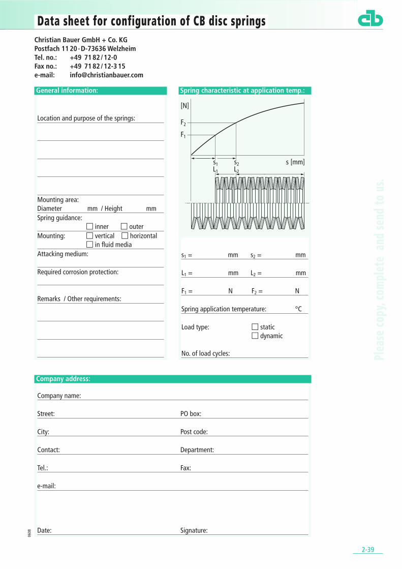
Spring characteristic at application temp.:
s1 = mm s2 = mm
L1 = mm L2 = mm
F1 = N F2 = N
Spring application temperature: °C
Load type: � static � dynamic
No. of load cycles:
General information:
Location and purpose of the springs:
Mounting area: Diameter mm / Height mmSpring guidance:
� inner � outerMounting: � vertical � horizontal
� in fluid mediaAttacking medium:
Required corrosion protection:
Remarks / Other requirements:
Company address:
Company name:
Street: PO box:
City: Post code:
Contact: Department:
Tel.: Fax:
e-mail:
Date: Signature:
0608
Christian Bauer GmbH + Co. KGPostfach 11 20 · D-73636 WelzheimTel. no.: +49 71 82 / 12-0Fax no.: +49 71 82 / 12-3 15e-mail: [email protected]
Plea
se co
py, c
ompl
ete
and
send
to u
s.
CHRISTIAN BAUER GMBH + CO. KGPostfach 11 20 D-73636 Welzheim
Telefon: +49/ 71 82/ 12-0Telefax: +49/ 71 82/ 12-315E-Mail: [email protected]: www.christianbauer.com
EnglandBauer Springs Ltd.Eagle RoadNorth Moons Moat Ind. EstateGB-Redditch Worcs. B98 9HFTelefon: + 44/ 15 27-594 900Telefax: + 44/ 15 27-594 909E-Mail: [email protected]: www.bauersprings.co.uk
USABauer Springs Inc.509 Parkway View DriveParkway West Ind. ParkUSA-Pittsburgh, PA. 15205Telefon: +1/ 412-787-79 30Telefax: +1/ 412-787-38 82E-Mail: [email protected]: www.bauersprings.com


![United States Live Load Deflection of Department of ...recommended deflection-values, he found that they ranged from L/200 to L/1,200. [24] also recommends values for maximum deflection](https://static.fdocuments.in/doc/165x107/5e73d03912540a19a6356f7c/united-states-live-load-deflection-of-department-of-recommended-deflection-values.jpg)


![NCHRP Web Document 46: Improved Live Load Deflection Criteria … · NCHRP Web Document 46 (Project 20-7[133]): Contractor’s Final Report Improved Live Load Deflection Criteria](https://static.fdocuments.in/doc/165x107/5acf99db7f8b9ac1478cfd54/nchrp-web-document-46-improved-live-load-deflection-criteria-web-document-46.jpg)


