R-136 - Load-Deflection Tests on Corrugated Multi-Plate Sections
European Journal of Molecular & Clinical Medicine ISSN 2515-8260 Volume 07, Issue 08, 2020
559
Abstract: One of the biggest obstacles that prevents emerging concrete types to become
widely adopted in construction is the deficiency of standardization background in practice
codes for these materials, despite the fact it possess superior properties, such as Ultra-high
Performance Fiber Reinforced Concrete (UHPFRC). In this study, Finite Element Analysis
(FEA) is utilized to simulate the behavior of UHPFRC and Normal Concrete (NC) simply
supported beams under static flexural loading. Abaqus software has been used in which a
simplified version of the Concrete Damage Plasticity Model (CDPM) was chosen as a
non-linear constitutive model. The model has been validated against conventional CDPM at
global (load-deflection) and local (load-stain) levels. Reinforced UHPFRC beam models
showed clearly matching response with the validity research paper (reference study)
experimental findings. The response of UHPFRC beams has been compared to NC beams.
This comparison has been explained in detail and checked with similar material
comparisons in the literature. The proposed study has revealed and compared the
distribution of cracks in the form of tension and compression damage for both materials. As
a conclusion, modelling is an effective way to predict the behavior of concrete beams in
which the relative local response was captured in reinforcement bars.
Numerical Simulation Study On Load Deflection
Of Reinforced Ultra High Performance Fiber
Reinfoeced Concrete And Normal Concrete
Beams Under Static Load
Anas Ammar Al-Kabasi1, Ali Saif Al-Wardi
2, Qadir Bux alias Imran Latif
3, Nasrellah Hassan
Ahmed4
1Bachelor student, Civil and Environmental Engineering, University of Nizwa, Nizwa Province,
Ad Dakhiliyah Governorate, Sultanate of Oman, 2Bachelor student, Civil and Environmental Engineering, University of Nizwa, Nizwa Province,
Ad Dakhiliyah Governorate, Sultanate of Oman, 3Department of Civil and Environmental Engineering, College of Engineering and
Architecture, University of Nizwa, Nizwa Province, Ad Dakhiliyah Governorate, P.O. Box 33,
P.C. 616, Sultanate of Oman, 4 Department of Civil and Environmental Engineering, College of Engineering and
Architecture, University of Nizwa, Nizwa Province, Ad Dakhiliyah Governorate, P.O. Box 33,
P.C. 616, Sultanate of Oman,
Emails: [email protected]
European Journal of Molecular & Clinical Medicine ISSN 2515-8260 Volume 07, Issue 08, 2020
560
Key words: Finite Element Method (FEM), steel, Flexure, UHPFRC, Concrete, Load,
deflection, strain.
1. INTRODUCTION
One of the modern concrete classes recently discovered (mid of 1990s) is the UHPFRC, a new
material with superior properties. Likewise all new concrete types, it was developed due to the
need of concrete with improved quality. When compared to conventional concrete, UHPFRC
has different characteristics like high content of binder, fine aggregate size, presence of fibers
and the use of large amount of super-plasticizers. It was developed by relying on the advanced
material technologies in which the fine weak spots like pores and micro-crakes are minimized
to increase the load carrying capacity of the material [1]; this was achieved due to the high
binder content and low W/B ratio which leads to the absence of capillary porosity. Whereas the
fibers are introduced to improve the tensile strength of the cementitious material as well as to
enhance the ductile behavior. Although it has unique properties, UHPFRC is not widely used in
construction due to high cost of the material itself and the lack of practical design code
regulations along with the high testing costs.
Abaqus/CAE, or "Complete Abaqus Environment" (a backronym with an obvious root in
Computer-Aided Engineering) is a three-dimensional finite element (FE) package with
advanced modelling capabilities which is mostly utilized as a research tool [2]. It has many
commands to create variety of elements and wide range of material constitutive models to
simulate the behavior of most typical materials. Simulation using such models plays an
important role in minimizing the number of experimental tests needed to establish accurate
response of the materials [3]. As a consequence, the ultimate benefit of any simulation research
will be in terms of saving time, money and effort especially when the material under
consideration or testing machine needed are not available or require huge budget. Even one can
avoid doing any checking tests by referring to test results of previous studies. The practice is
changing towards focusing on the numerical model only and not to perform any experimental
testing; since many tests are already done in the past. In case of new material, only few tests are
necessary for the identification of constitutive model parameters [4].
Several laboratory investigations on the behavior of UHPFRC beams under load were
conducted. These tests came out with a conclusion stating that higher fiber content will increase
the beam flexural and shear capacities. Only few numerical simulation studies have mentioned
the structural behavior of UHPFRC beam. Studies that simulated the response of UHPFRC
members using finite element based numerical method have indicated that the prediction of
allowable load capacity by relying on the finite element model can give results with a high
degree of accuracy. However, these studies has performed experiments to a small extent and
accounts only for global response of UHPFRC without considering the local response (strain
and cracking). Finite element based numerical modelling was conducted in the research paper
by (Solhmirzaei & Kodur, 2017) [5] to overcome this deficiency of numerical studies on
UHPFRC beams, in which the paper is focusing on the structural member response globally
and locally. The local behavior was taken as the overall strain in steel reinforcement at
mid-span although experimental results have shown obvious difference between center bars
and corner bars. It was unclear whether Abaqus software is able to capture this difference based
on FEM, so it is required to find out the local response of center bars relative to corner bars. In
addition, the advantage of UHPFRC over the NC was evaluated as a ratio of load capacity and
then the obtained proportions are related to proportions from previous studies in flexure.
European Journal of Molecular & Clinical Medicine ISSN 2515-8260 Volume 07, Issue 08, 2020
561
(Shafieifar, Farzad, & Azizinamini, 2017) [6] have already compared between the two
materials experimentally and numerically but in terms of testing that is performed on small
specimens for the purpose of getting the mechanical properties.
Emerging materials such as UHPFRC require more investigation in order to establish the main
guidelines for design and construction practice, while frequent testing on such material is not
feasible due to the variety of its specifications in terms of fiber detailing (Singh, Sheikh, Ali,
Visintin, & Griffith, 2017) [7]. An alternative approach is necessary to deal with this lack of
material standardization. With the aid of FE package such as Abaqus, it is possible to predict
precisely the behavior of concrete not only in a cost effective way, but it reduces time and effort
as it will replace the conventional material testing [2]. This investigation will go further by
studying the behavior of structural element itself instead of small specimens and then check
simulation output with experimental data available in the literature.
2. LITERATURE REVIEW
Simulation researches became a trend in most of the educational institutions around the world,
especially in engineering applications. The literature provides many researches on the
modelling of concrete using Abaqus software or other software programs. Herein we are going
to refer to some of the published papers related to this project. Only studies of the flexural
response with CDPM are included in a chronological order with some investigations on
UHPFRC compared with NC.
(Wahalathantri, Thambiratnam, Chan, & Fawzia, 2011) [8]: CDPM was used to compare the
non-linear behavior of reinforced concrete elements experimentally and numerically. 3 point, 4
point and un-symmetric 3 point bending tests are modeled and compered with real test results.
The model shows very good agreement with the test results, namely the accuracy of
displacement values was in the range of 95% to 98%.
(Deng, Qie, & Wang, 2015) [9]: Simply supported reinforced concrete beam was modeled with
CDPM using Abaqus. Through steel bar embedment and concrete failure definition by
damaging, the model showed similarity to a large extent in mid-span deflection when compared
with testing deflection. It was stated that Abaqus is precise but more investigations are needed
to avoid small differences in the results.
(Singh, Sheikh, Ali, Visintin, & Griffith, 2017) [7]: Due to the urgent need for a methodology
that saves the amount of testing required for materials having no background and due to the
variety of UHPFRC specifications and detailing, it is necessary to rely on FE models. The study
focused on the flexural behavior of steel reinforced UHPFRC beams under 3 and 4 point
bending tests and models were developed using CDPM. The results showed very good
agreement in terms of load carrying capacity and load-deflection curve with ability to capture
the entire load-deflection response from the start of loading until failure.
(Hafezolghorani, Hejazi, Vaghei, Jaafar, & Karimzade, 2017) [10]: Behavior of simply
supported partially pre-stressed beams was modeled with Simplified Concrete Damage
Plasticity Model (SCDPM) for grades B20, B30, B40 and B50. The mid-span displacement
was compared with empirical deflection formulation and with the conventional CDPM. The
clear correlation between the suggested SCDPM and the other two approaches leaded to
describe simplified model as "realistic" due to its ability to detect the damage in tension and
European Journal of Molecular & Clinical Medicine ISSN 2515-8260 Volume 07, Issue 08, 2020
562
compression of concrete along with the mid-span displacement.
(Solhmirzaei & Kodur, 2017) [5]: The response of UHPFRC beams under flexural and shear
loading was modeled using CDPM. The response of UHPFRC beam obtained from the
numerical model was compared to virtual test results. In conclusion it was stated that the model
was able to capture the overall experimental response during all stages of loading. Results
agreement was proven globally through load-displacement curve and locally through
load-strain curve on rebar at mid span. This is the only paper was found in which the local
behavior is taken into account.
(Shafieifar, Farzad, & Azizinamini, 2017) [6]: A general comparison between Ultra-high
Performance Concrete (UHPC) and NC in terms of mechanical properties and behavior in
order to demonstrate the superior characteristics of UHPC over the NC. Compression and
tension tests were conducted on specimens of both materials. FE numerical model was utilized
using Concrete Damage Plasticity (CDP) to simulate the behavior of same materials.
Compressive strength of UHPC was three to four times the strength of NC, tensile strength was
two to four times and flexural strength was 4.5 times. Material parameters obtained from
numerical modeling have good agreement with the actual properties.
(Pourbaba, Sadaghian, & Mirmiran, 2019) [11]: Experimental investigation was done for the
flexural and shear behavior of five UHPC beams. Four point bending test was performed on
concrete specimens, compared with laboratory results of five Normal Strength Concrete (NSC)
beams. The analysis of failure mechanisms and crack distribution pointed out that bending
caused the failure in UHPC beams while NSC beams failed by shear. Results showed that the
experimental flexural and shear capacities of UHPC specimens are greater than NSC
specimens up to 3.5 times. Comparison of experimental values with theoretical values
represents moderate estimation for low reinforcement ratios in most of the models.
3. METHODOLOGY/MATERIALS
3.1 Experimental Details
The beam was tested in flexure in which four-point bending test has been modeled when a
static load is applied, then model results were compared with data provided by (Solhmirzaei &
Kodur, 2017) [5] from which same test layout has been followed with similar UHPFRC
properties. Also beams are introduced with two configurations, either 3 or 4 tension bars, so
that two models are made for each concrete type as shown in Table-1. The units of quantities in
all four models are in Millimeters for length, Newton for force and Mega pascal for stress [3].
In simulation, force has to be applied by rigid surface [12]. To satisfy this condition, the model
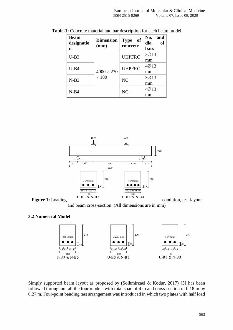
includes two plates with dimensions of 180×60×20 mm as shown in Figure 1. The load which
was applied on both plates is a pressure load with a total force of 107.7 kN for U-B3 and 126.6
kN for U-B4 (half load magnitude on each plate). Moreover, the beam is simply supported with
other two plates, one is pinned (or hinged) and other is roller support. For the material
nonlinearity, elastic properties has been considered for liner stage and plastic properties for
non-liner stage when all the parameters of concrete and steel are fed into Abaqus program [4].
European Journal of Molecular & Clinical Medicine ISSN 2515-8260 Volume 07, Issue 08, 2020
563
Table-1: Concrete material and bar description for each beam model
Beam
designatio
n
Dimension
(mm)
Type of
concrete
No. and
dia. of
bars
U-B3
4000 × 270
× 180
UHPFRC 313
mm
U-B4 UHPFRC 413
mm
N-B3 NC 313
mm
N-B4 NC 413
mm
Figure 1: Loading condition, test layout
and beam cross-section. (All dimensions are in mm)
3.2 Numerical Model
Simply supported beam layout as proposed by (Solhmirzaei & Kodur, 2017) [5] has been
followed throughout all the four models with total span of 4 m and cross-section of 0.18 m by
0.27 m. Four-point bending test arrangement was introduced in which two plates with half load
European Journal of Molecular & Clinical Medicine ISSN 2515-8260 Volume 07, Issue 08, 2020
564
magnitude is being applied on each plate. Two different reinforcement layouts have been
simulated with concrete cover in the longitudinal direction of 45 mm. Cover to reinforcement
in other directions, beam dimensions and rebar detailing are shown in Figure 1. During model
formation, for both concrete and steel bars, the 3D 8-Node Solid Brick Element with Reduced
Integration (C3D8R) has been selected [2]. The bonding between the reinforcement bars and
beam has been formed by introducing embedded region constraint for the bars inside the beam
(host region) from the interaction section in Abaqus [3], [4].
In Abaqus analysis user guide, section 2.2.4 (Defining rebar as an element property) which is
linked to section 23.6.3 (Concrete damaged plasticity), it was stated that the definition of rebar
layer emended in solid element has to be as a Continuum (Solid) Element (C3D8). Also it is
mentioned that beam element cannot be used for steel reinforcement as it include shear stress
caused by torsion. Based on these two statements, both material elements (concrete and steel)
are set as 3D 8-Node Solid Brick Element with Reduced Integration (C3D8R) [3], [4].
3.3 Material Properties
The ultimate compressive strength fcu for UHPFRC is 193 MPa and tensile strength is 7.11
MPa. The properties of NC are taken from numerical simulation study by (Hafezolghorani,
2017) [10] with concrete grade of B50 (50 MPa) and tensile strength of 5 MPa. Even though it
was used with partially pre-stressed beam, in this study 50 MPa strength has been selected as
the maximum strength of NC. UHPFRC yield strain is 0.0044 while ultimate strain is 0.008.
All other parameters are shown in Table-2 including elasticity and concrete damage plasticity
parameters. Steel properties are as shown in Table-3. Stress-strain response of UHPFRC
material in Table-4 is necessary to calculate the damage plasticity parameters using the
Simplified Concrete Damage Plasticity Model (SCDPM) [10] including inelastic (or crushing)
strain, cracking strain, compression damage and tension damage.
Table 2: Material properties of UHPFRC and NC
Concrete Property UHPFRC NC
Elasticity parameters Young's Modulus, E 43970 MPa
33400
MPa
Poisson's ratio, ν 0.2 0.2
Concrete damage
plasticity (CDP)
parameters
Dilation angle, ψ 39° 31°
Eccentricity, ξ 0.1 0.1
Biaxial stress ratio, σb0/σc0 1.16 1.16
Second stress invariant ratio on
tensile meridian, kc 2/3 0.67
Viscosity parameter, μ 0.0001 0
Table 3: Material properties of steel reinforcement
Elasticity
parameters
Young's Modulus, E 207000 MPa
Poisson's ratio, ν 0.3
Plasticity
parameters
Tensile yield strength, fy 435 MPa
Tensile yield strain, εy 0.0021
Tensile ultimate strength, fu 700 MPa
Tensile ultimate strain, εu 0.12

European Journal of Molecular & Clinical Medicine ISSN 2515-8260 Volume 07, Issue 08, 2020
565
Table 4: Uniaxial stress-strain response of UHPFRC in compression and tension
Compressive response Tensile response
Stress
(MPa) Strain 187 0.00510
Stress
(MPa) Strain
0 0.00000 177 0.00530 0.001 0.00000
100 0.00230 118 0.00600 7.110 0.00033
150 0.00350 77 0.00640 7.110 0.00200
167 0.00390 33 0.00700 6.110 0.00830
193 0.00490 9 0.00820 0.100 0.01800
4. RESULTS AND FINDINGS
Four models have been developed based on one complete model. After getting first model
results, the model assembly is modified to form the other steel bar configuration and then
material properties are changed to model the other material. When analysis results are shown, a
variety of visual outcomes (e.g. stress, strain, displacement, reaction force...etc.) will appear on
the beam deflected shape and expressed by a range of colors and each color refers to a certain
value as proposed by the legend. Numerical values for each result (outcome) are taken using
Output Database (ODB) command and all the values are transferred to an excel sheet to
represent the tabular format values as graphical curves. In addition, the extracted results were
illustrated as visual images and comparison tables.
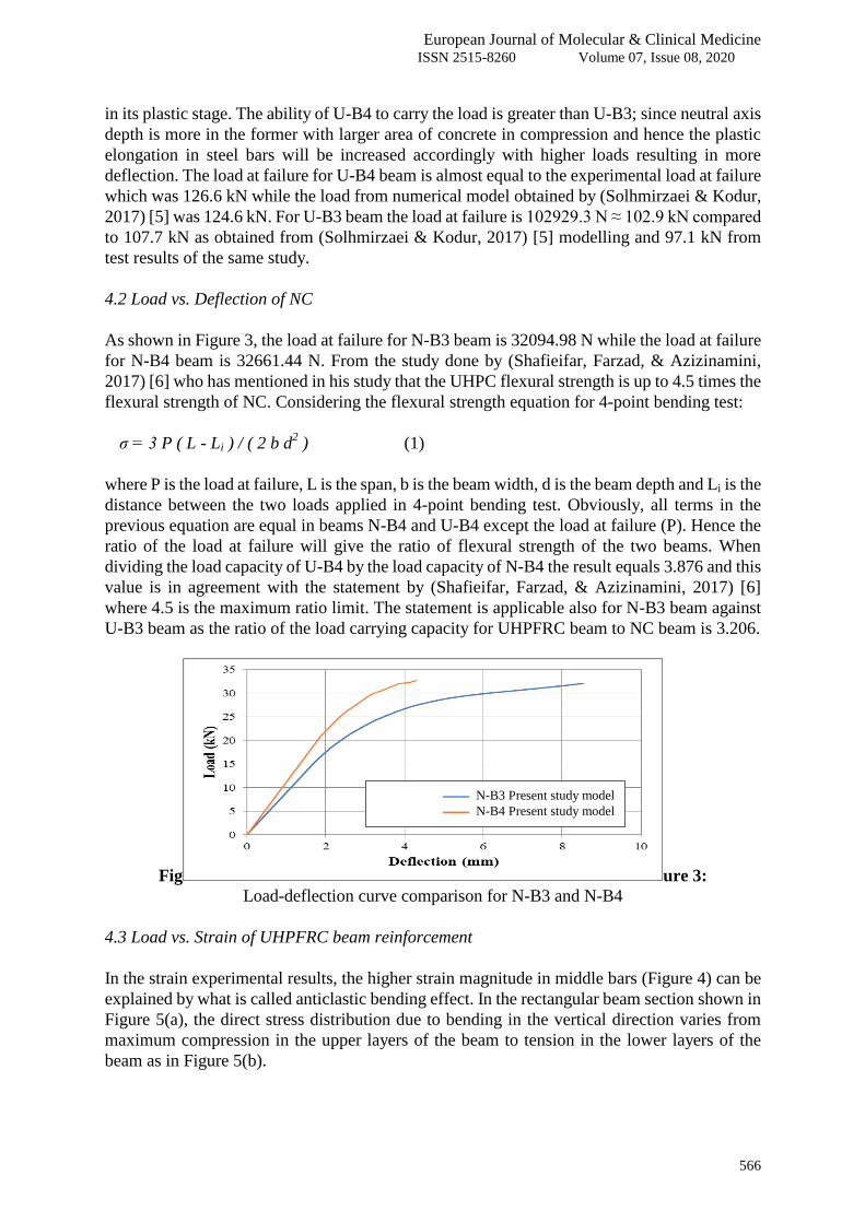
4.1 Load vs. Deflection of UHPFRC
Figure
2: Load-deflection curve comparison for U-B4 and U-B3
As Figure 2 demonstrates, the load-deflection curve obtained for U-B4 is quite satisfactory
when compared to experimental data. It can be seen that the response of the two beams has
different stages starting from linear elastic stage until crack initiation in tension followed by
post-cracking stage with linear response for rebar until steel yielding then finally plastic
deformation until peak load with continuous curve up to the stage of approaching failure with
fully plastic response. For U-B4 beam in Figure 2, the three curves have exhibit almost the
same behavior in plastic stage but for the elastic stage there are three distinct paths. This
difference can be explained by referring back to the test arrangement. The breadth of the spot
(plate) at which the load is applied will affect the load intensity and hence the slop of the elastic
linear curve will be inversely proportional to the load spot breadth. U-B4 beam gives higher
deflection than U-B3 due to the occurrence of concrete failure while the steel reinforcement is
U-B4 Experimentــــــــــ
U-B4 Solhmirzaei modelـ ـ ـ ـ ـ
U-B4 Present study modelــــــــــ
U-B3 Present study modelــــــــــ
European Journal of Molecular & Clinical Medicine ISSN 2515-8260 Volume 07, Issue 08, 2020
566
in its plastic stage. The ability of U-B4 to carry the load is greater than U-B3; since neutral axis
depth is more in the former with larger area of concrete in compression and hence the plastic
elongation in steel bars will be increased accordingly with higher loads resulting in more
deflection. The load at failure for U-B4 beam is almost equal to the experimental load at failure
which was 126.6 kN while the load from numerical model obtained by (Solhmirzaei & Kodur,
2017) [5] was 124.6 kN. For U-B3 beam the load at failure is 102929.3 N ≈ 102.9 kN compared
to 107.7 kN as obtained from (Solhmirzaei & Kodur, 2017) [5] modelling and 97.1 kN from
test results of the same study.
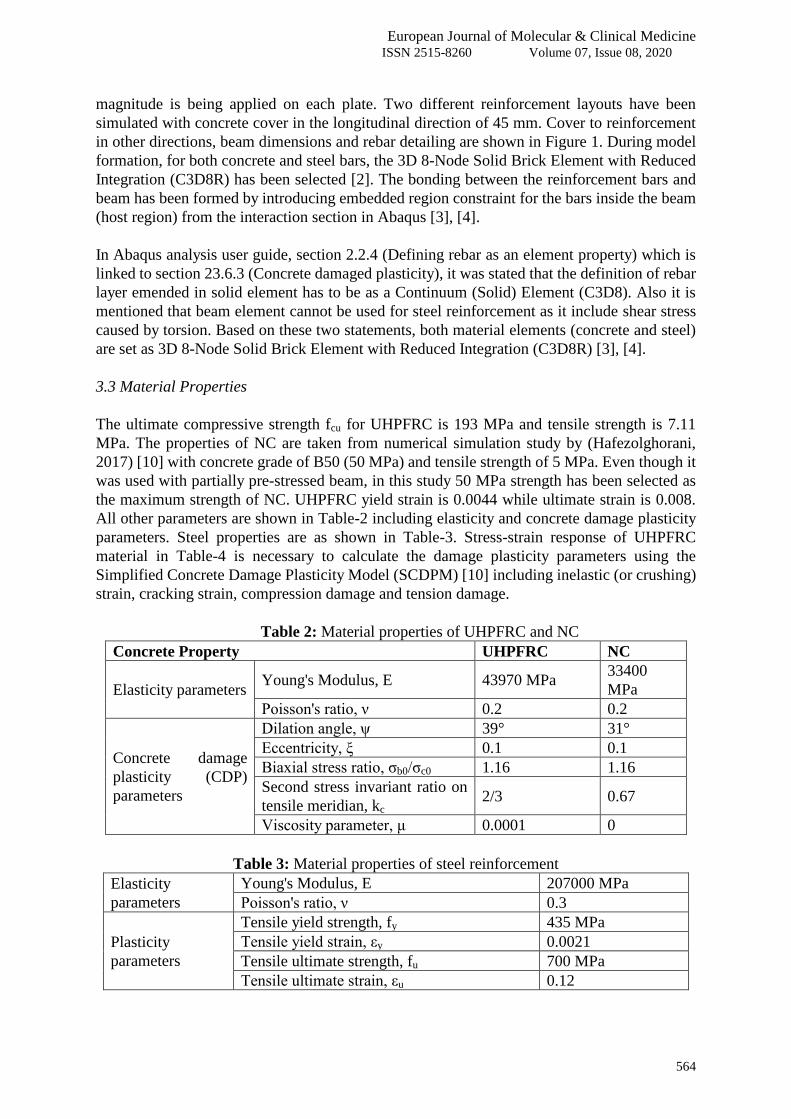
4.2 Load vs. Deflection of NC
As shown in Figure 3, the load at failure for N-B3 beam is 32094.98 N while the load at failure
for N-B4 beam is 32661.44 N. From the study done by (Shafieifar, Farzad, & Azizinamini,
2017) [6] who has mentioned in his study that the UHPC flexural strength is up to 4.5 times the
flexural strength of NC. Considering the flexural strength equation for 4-point bending test:
σ = 3 P ( L - Li ) / ( 2 b d2 ) (1)
where P is the load at failure, L is the span, b is the beam width, d is the beam depth and Li is the
distance between the two loads applied in 4-point bending test. Obviously, all terms in the
previous equation are equal in beams N-B4 and U-B4 except the load at failure (P). Hence the
ratio of the load at failure will give the ratio of flexural strength of the two beams. When
dividing the load capacity of U-B4 by the load capacity of N-B4 the result equals 3.876 and this
value is in agreement with the statement by (Shafieifar, Farzad, & Azizinamini, 2017) [6]
where 4.5 is the maximum ratio limit. The statement is applicable also for N-B3 beam against
U-B3 beam as the ratio of the load carrying capacity for UHPFRC beam to NC beam is 3.206.
Fig ure 3:
Load-deflection curve comparison for N-B3 and N-B4
4.3 Load vs. Strain of UHPFRC beam reinforcement
In the strain experimental results, the higher strain magnitude in middle bars (Figure 4) can be
explained by what is called anticlastic bending effect. In the rectangular beam section shown in
Figure-5(a), the direct stress distribution due to bending in the vertical direction varies from
maximum compression in the upper layers of the beam to tension in the lower layers of the
beam as in Figure 5(b).
N-B3 Present study modelــــــــــ
N-B4 Present study modelــــــــــ
European Journal of Molecular & Clinical Medicine ISSN 2515-8260 Volume 07, Issue 08, 2020
567
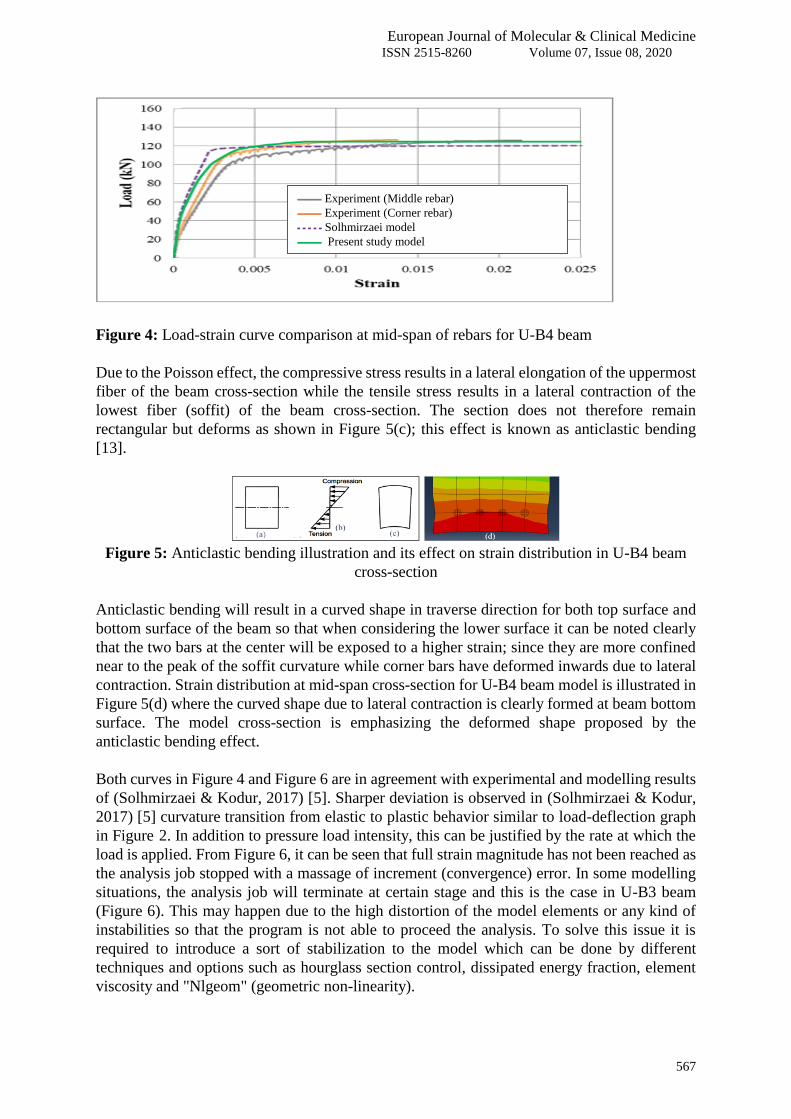
Figure 4: Load-strain curve comparison at mid-span of rebars for U-B4 beam
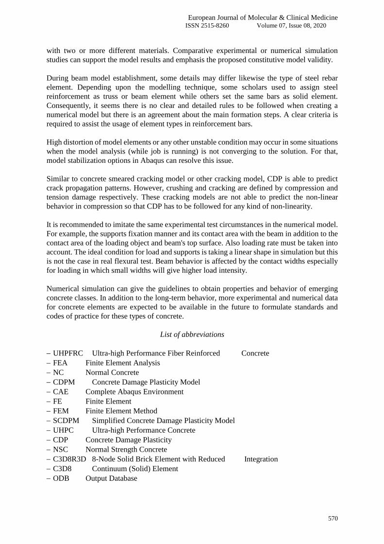
Due to the Poisson effect, the compressive stress results in a lateral elongation of the uppermost
fiber of the beam cross-section while the tensile stress results in a lateral contraction of the
lowest fiber (soffit) of the beam cross-section. The section does not therefore remain
rectangular but deforms as shown in Figure 5(c); this effect is known as anticlastic bending
[13].
Figure 5: Anticlastic bending illustration and its effect on strain distribution in U-B4 beam
cross-section
Anticlastic bending will result in a curved shape in traverse direction for both top surface and
bottom surface of the beam so that when considering the lower surface it can be noted clearly
that the two bars at the center will be exposed to a higher strain; since they are more confined
near to the peak of the soffit curvature while corner bars have deformed inwards due to lateral
contraction. Strain distribution at mid-span cross-section for U-B4 beam model is illustrated in
Figure 5(d) where the curved shape due to lateral contraction is clearly formed at beam bottom
surface. The model cross-section is emphasizing the deformed shape proposed by the
anticlastic bending effect.
Both curves in Figure 4 and Figure 6 are in agreement with experimental and modelling results
of (Solhmirzaei & Kodur, 2017) [5]. Sharper deviation is observed in (Solhmirzaei & Kodur,
2017) [5] curvature transition from elastic to plastic behavior similar to load-deflection graph
in Figure-2. In addition to pressure load intensity, this can be justified by the rate at which the
load is applied. From Figure 6, it can be seen that full strain magnitude has not been reached as
the analysis job stopped with a massage of increment (convergence) error. In some modelling
situations, the analysis job will terminate at certain stage and this is the case in U-B3 beam
(Figure 6). This may happen due to the high distortion of the model elements or any kind of
instabilities so that the program is not able to proceed the analysis. To solve this issue it is
required to introduce a sort of stabilization to the model which can be done by different
techniques and options such as hourglass section control, dissipated energy fraction, element
viscosity and "Nlgeom" (geometric non-linearity).
Experiment (Middle rebar)ــــــــــ
Experiment (Corner rebar)ــــــــــ
Solhmirzaei modelـ ـ ـ ـ ـ
Present study modelــــــــــ

European Journal of Molecular & Clinical Medicine ISSN 2515-8260 Volume 07, Issue 08, 2020
568
Figure 6: Load-strain curve comparison at mid-span of rebars for U-B3 beam
4.4 Visual Damage
Figure 7: Side view of tension damage distribution for U-B3 and N-B3 beams
Figure 8: Bottom view of tension damage distribution for U-B3 and N-B3 beams
From Figure 7, it can be seen that longer cracks are formed in NC beams up to the beam
mid-height starting from the bottom as discrete tension cracks. Whereas the UHPFRC beam
has shown limited crack length in the tension zone and cracks at the beam soffit are not
continues through the beam width as shown in Figure 8. When referring back to the
composition of the two materials, it can be inferred that the fibers in UHPFRC beam act as a
bridge for the cracks with strong interlocking to the concrete matrix and therefore severe crack
propagation is prohibited. This explains the observations of damage in which the damage in
UHPFRC beams is smooth and gradually distributed in limited areas, whereas in NC beams
separated cracks have taken place within larger range around the weak spots of the beam mass.
There is no compression damage in N-B3 and N-B4 beams because the failure in these beams
was in the tension zone only.
5. CONCLUSIONS AND RECOMMENDATIONS
5.1 Conclusions
The numerical model (CDP) was used to get the behavior of UHPFRC and NC beams under
static loading. It captured the structural response from the moment of applying the load until
failure. The load at failure is near to the load obtained by experimental test. In general, the
results of the two UHPFRC models are matching with the experimental findings in both: global
(load-deflection) and local (load-strain) levels. Furthermore, damage expectations, cracking
patterns and failure modes are quite satisfactory for the two materials. The main comparisons
and observations in this study are:
-Experimentــــــــــ
-Solhmirzaei modelـ ـ ـ ـ ـ
-Present study modelــــــــــ

European Journal of Molecular & Clinical Medicine ISSN 2515-8260 Volume 07, Issue 08, 2020
569
Load capacity of UHPFRC beam is around 3 to 4 times the load capacity of NC beam
when both beams are steel reinforced.
The beam deflection is reduced as more reinforcement bars are added only when the
concrete fails while bars are still in the elastic stage and this is the case in NC due to its
brittleness. On the other hand, more bars in UHPFRC beam can result in higher
deflection as bars are in plastic stage at the point of beam failure and hence more bars will
undertake plastic elongation resulting in additional deformation. Since UHPFRC is
ductile rather than brittle, it has the opposite behavior of NC beam.
At high concrete grades, adding one rebar has more effect than the addition of the same
bar at lower grades. The load carrying capacity difference between 3 bar and 4 bar beams
in UHPFRC is 23.7 KN (see Figure 2), while this difference in NC beams is 0.566 KN
(see Figure 3).
Abaqus software assumes that all test elements and arrangements are ideal including geometry,
material properties, load application and beam supporting conditions. Due to software
idealization, FE model showed stiffer behavior when compared to experimental test response.
This can be seen clearly in Figure-2 where a horizontal (fully plastic) curve represents the
numerical model response but the experimental result was different with a dip in load value
after reaching the maximum value (load at failure). Concrete and steel material properties with
the associated geometry and test circumstances are unideal in virtual test but they are not in the
FE model. Different assumptions regarding test idealization gave two different curves.
Load-deflection and load-strain curves are influenced by the load intensity mostly in the elastic
stage in which different slopes are observed for model and experiment. Load applied on wider
element will give less intensity and vice versa. Load application rate has also an important role
in beam behavior. It can be stated that load application in real flexural test was more gradual
when compared to numerical model.
SCDPM has proven its reliability for a wide range of concrete classes including high strength
concretes such as UHPFRC. Fibers action in UHPFRC which enhance the material ductility
was captured clearly when the damage of UHPFRC and NC beams was compared. Considering
UHPFRC model outcomes, CDPM was able to imitate the behavior of quasi-brittle material
effectively even though it is used mainly to model brittle materials such as concrete and
concrete like materials. It offers the ability to define failure mechanisms in any element of
concrete structure.
5.2 Recommendations
As SCDPM has few parameters to be defined compared to other constitutive models, it is
recommended to adopt this simplified model when making several simulation models of
different conditions. The simplified model is showing a quite satisfactory degree of accuracy.
It is possible to improve the simulation results of existing modeling studies in the literature by
using different modelling techniques. Also when creating new models, other assumptions can
be made like reducing the load intensity instead of using line load on the beam (ideal case).
Checks on both global and local levels are necessary when using the same constitutive model
European Journal of Molecular & Clinical Medicine ISSN 2515-8260 Volume 07, Issue 08, 2020
570
with two or more different materials. Comparative experimental or numerical simulation
studies can support the model results and emphasis the proposed constitutive model validity.
During beam model establishment, some details may differ likewise the type of steel rebar
element. Depending upon the modelling technique, some scholars used to assign steel
reinforcement as truss or beam element while others set the same bars as solid element.
Consequently, it seems there is no clear and detailed rules to be followed when creating a
numerical model but there is an agreement about the main formation steps. A clear criteria is
required to assist the usage of element types in reinforcement bars.
High distortion of model elements or any other unstable condition may occur in some situations
when the model analysis (while job is running) is not converging to the solution. For that,
model stabilization options in Abaqus can resolve this issue.
Similar to concrete smeared cracking model or other cracking model, CDP is able to predict
crack propagation patterns. However, crushing and cracking are defined by compression and
tension damage respectively. These cracking models are not able to predict the non-linear
behavior in compression so that CDP has to be followed for any kind of non-linearity.
It is recommended to imitate the same experimental test circumstances in the numerical model.
For example, the supports fixation manner and its contact area with the beam in addition to the
contact area of the loading object and beam's top surface. Also loading rate must be taken into
account. The ideal condition for load and supports is taking a linear shape in simulation but this
is not the case in real flexural test. Beam behavior is affected by the contact widths especially
for loading in which small widths will give higher load intensity.
Numerical simulation can give the guidelines to obtain properties and behavior of emerging
concrete classes. In addition to the long-term behavior, more experimental and numerical data
for concrete elements are expected to be available in the future to formulate standards and
codes of practice for these types of concrete.
List of abbreviations
UHPFRC Ultra-high Performance Fiber Reinforced _____Concrete
FEA Finite Element Analysis
NC Normal Concrete
CDPM Concrete Damage Plasticity Model
CAE Complete Abaqus Environment
FE Finite Element
FEM Finite Element Method
SCDPM Simplified Concrete Damage Plasticity Model
UHPC Ultra-high Performance Concrete
CDP Concrete Damage Plasticity
NSC Normal Strength Concrete
C3D8R3D 8-Node Solid Brick Element with Reduced ____Integration
C3D8 Continuum (Solid) Element
ODB Output Database
European Journal of Molecular & Clinical Medicine ISSN 2515-8260 Volume 07, Issue 08, 2020
571
6. REFERENCES
[1] Awinda, K. & Chen, Jiye & Barnett, Stephanie & Fox, D.. Modelling behaviour of ultra
high performance fibre reinforced concrete. Advances in Applied Ceramics, pp. 502 –
508, 2014.
[2] Rahman, I., Latif, Q., Zaidi, A. A., Nor, N., & Abdullah, S.. Simulation study on effect of
diameter and CRH ratio of ogive nose hard missile on required critical impact
energy for penetration of concrete targets. International Review on Modelling and
Simulations, 4(3), 2011.
[3] Imran Latif, Q. B., Rahman, I. A., & Zaidi, A. M.. Ogive nose hard missile penetrating
concrete slab numerical simulation approach. International Journal on Advanced
Science, Engineering and Information Technology, vol. 1(6), pp. 586-591, 2011.
[4] Imran Latif, Q. B., Al-Nuaimi, A., & Jamrah, A.. Critical Impact Energy of Flat Nose
Hard Projectile Causing Early Scabbing in Concrete Slab. International Journal of
Advances in Applied Sciences (IJAAS), vol. 3, pp. 112-121, 2014.
[5] Solhmirzaei, Roya & Kodur, Venkatesh.. Modeling the response of ultra high
performance fiber reinforced concrete beams. 6th International Workshop on
Performance, Protection & Strengthening of Structures under Extreme Loading,
PROTECT2017, Guangzhou (Canton), China: Procedia Engineering 210, pp. 211-219,
2017.
[6] Shafieifar, Mohamadreza & Farzad, Mahsa & Azizinamini, Atorod.. Experimental and
numerical study on mechanical properties of Ultra High Performance Concrete
(UHPC). Construction and Building Materials, pp. 402-411, 2017.
[7] Singh, Manpreet & Sheikh, Abdul & Ali, Mohamed & Visintin, Phillip & Griffith, M..
Experimental and numerical study of the flexural behavior of ultra-high
performance fibre reinforced concrete beams. Construction and Building Materials,
pp. 12-25, 2017.
[8] Wahalathantri, Buddhi & Thambiratnam, David & Chan, Tommy & Fawzia, Sabrina.. A
material model for flexural crack simulation in reinforced concrete elements. First
International Conference on Engineering, Designing and Developing the Built
Environment for Sustainable Wellbeing. Brisbane: Queensland University of
Technology, pp. 260-264, 2011.
[9] Deng, Sihua & Qie, Ze & Wang, Li.. Nonlinear Analysis of Reinforced Concrete Beam
Bending Failure Experimentation Based on ABAQUS. International Conference on
Information Sciences, Machinery, Materials and Energy (ICISMME 2015), pp. 440-444,
2015.
[10] Hafezolghorani, Milad & Hejazi, Farzad & Vaghei, Ramin & Jaafar, Mohd & Karimzade,
Keyhan. Simplified Damage Plasticity Model for Concrete. Structural Engineering
International, pp. 68-78, 2017.
[11] Pourbaba, M., Sadaghian, H., & Mirmiran, A.. A comparative study of flexural and
shear behavior of ultra-high-performance fiber-reinforced concrete beams.
Advances in Structural Engineering, pp. 1-12, 2019.
[12] Jankowiak, T., & Lodygowski, T. Identification of parameters of concrete damage
plasticity constitutive model. Poznan, Poland: University of Technology, Institute of
Structural Engineering (ISE). Foundations of civil and environmental engineering, vol.
6(1), pp. 53-69, 2005.

European Journal of Molecular & Clinical Medicine ISSN 2515-8260 Volume 07, Issue 08, 2020
572
[13] Megson, T.H.G., Structural and Stress Analysis, 4th ed. Elsevier Ltd., 2019, ch. 9, pp.
252-253.