THE PICO-LIGHT Introduction · THE PICO-LIGHT Introduction The objective of the Pico-Light design...
32
1 THE PICO-LIGHT Introduction The objective of the Pico-Light design is to produce a small, light teardrop trailer suitable for the smallest tow vehicle including large motorcycles. This note describes and illustrates the design – working drawings follow after the text. To get the minimum weight, the trailer is built no stronger than it needs to be to do its job and uses only single-skin construction throughout. The trailer will serve its intended purpose well, but is not suitable for other uses – if you want to also use your trailer to, say, collect scrap batteries for recycling, pick another design. To get the minimum size, the trailer has been designed to be low, no more than is needed to enable the occupants to sit up with their heads nearly touching the roof and to be not much longer than the bed length. To fit in two people in bearable comfort, the width has been kept at the traditional teardrop four feet – if the trailer is intended only for solo use, the body width could be reduced. There is no galley and no hatch at the back, to save both weight and size. If a full galley is wanted, it can be built it into a traditional camp kitchen box that sits inside the cabin during towing and is taken out at the camp site. There are no lockers inside – that would need a bigger trailer. But there is a large shelf over the sleepers’ legs that provides somewhere to store clothes, etc while sleeping.
Transcript of THE PICO-LIGHT Introduction · THE PICO-LIGHT Introduction The objective of the Pico-Light design...

1
THE PICO-LIGHT Introduction
The objective of the Pico-Light design is to produce a small, light teardrop trailer suitable for the smallest tow vehicle including large motorcycles. This note describes and illustrates the design – working drawings follow after the text. To get the minimum weight, the trailer is built no stronger than it needs to be to do its job and uses only single-skin construction throughout. The trailer will serve its intended purpose well, but is not suitable for other uses – if you want to also use your trailer to, say, collect scrap batteries for recycling, pick another design. To get the minimum size, the trailer has been designed to be low, no more than is needed to enable the occupants to sit up with their heads nearly touching the roof and to be not much longer than the bed length. To fit in two people in bearable comfort, the width has been kept at the traditional teardrop four feet – if the trailer is intended only for solo use, the body width could be reduced. There is no galley and no hatch at the back, to save both weight and size. If a full galley is wanted, it can be built it into a traditional camp kitchen box that sits inside the cabin during towing and is taken out at the camp site. There are no lockers inside – that would need a bigger trailer. But there is a large shelf over the sleepers’ legs that provides somewhere to store clothes, etc while sleeping.

2
The body sides hang below the floor just for the look of it and styled (or over-styled!) fenders are used to give the little 8” wheels some character. Ready-made fenders can be used and if so it would make sense to eliminate the overhang on the body sides.
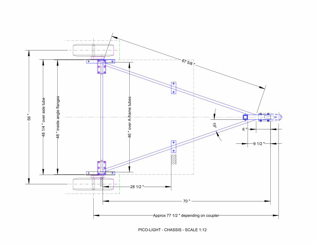
Warning: this trailer design has not been prototyped and prospective builders need to satisfy them-selves that it is large enough for their needs (and their claustrophobia…). This design is one size smaller than even a normal 8ft teardrop. Building a mock-up of the sleeping space in cardboard and trying it out would be sensible. This design was inspired by the Eis Piccolo made in Germany in the 1950s and that explains the ‘Pico’ in its name. Some may also recognise that Pico- is the prefix for a very small measure - it means 10-12. The free Generic Benroy plans on the Teardrop and Tiny Travel Trailers forum (http://www.mikenchell.com/forums) can be used for the many details of building a teardrop trailer. The body is self-supporting on the frame and to do this it must be well built – in particular all joints must be glued with a high quality glue, preferably epoxy. Mechanical fasteners alone, such as nails or screws, are not a satisfactory alternative. The completed trailer weighs approximately 280lb – a detailed weight estimate is included at the end of the drawings. Chassis The aim of the chassis is to be light and strong. It is suitable for this design but is not necessarily suitable for other heavier designs.

3
2”x1”x14ga rectangular box is used for the main rails of the frame. This frame design passes the Australian trailer rules for a utility trailer of 630lb, so that is probably sufficient for a 1200lb teardrop which will see much less abuse. There is sufficient spare capacity in the frame design to allow the tongue to be lengthened if required up to 24” longer than drawn – this can be down either by lengthening the A-frame rails (preferred) or by using a longer single 2”x2” tongue tube. The 14ga tube requires an expert welder to make good joints. For the less skilled welder, switching to the more common 11ga tube would be a safe alternative and would only cost 10lb extra weight. A single 2”x2”x11ga tongue right back to the axle cross-member can be used instead of the A-frame but this is not as stiff and should not be made any longer than drawn, to avoid snaking issues. To save weight, separate Flexiride half-axles of 425lb capacity per pair are used. These are unusual in the US but are the standard type for small trailers in Europe. Aligning the two half-axles to the frame needs to be done with a little care, but it does not require either a tame rocket scientist or automotive alignment equipment. The simple technique is to bolt the half-axles to their mounting plates, clamp the half-axles to a straight beam, align the joined half-axles and tack-weld the mounting plates to the axle cross-member. Re-move the half-axles before final welding the mounting plates . The body is supported by mounting plates under the front frame of the floor, and by two 12” long angles under the sidewalls. For a body built with care, this is quite sufficient support. A few 3/8” hold-down bolts with big washers are all that is needed to join the body to the frame. A standard trailer jack is overkill for this trailer which has only 40lb weight on the hitch, so a custom-made “propstand” (the British word for it) is used which weighs only 3.5lb in total. This consists of two square

4
tubes with a series of holes through the sides that allow a 1/4” pin (with a R-clip or similar locking feature) to provide height adjustment in 1” steps. Floor
The floor is made of 3/8” ply with mostly 1x2 framing underneath. This is quite sufficient for a trailer floor which will only be sat or laid on. It is not sufficiently strong to be walked on, but then it doesn’t need to be. The floor is framed as shown and then the front and back chamfers are cut – the floor could be built as drawn with the chamfers left uncut until after the sidewalls have been trial-fitted, to check the floor length. Where the floor frame cross-members pass over the frame rails, add 1/8” packing pieces (the thickness of the steel mounting plates) so the floor is supported by the frame rails. Making the front cross-member from hardwood would be sensible as this carries the A-frame load. Sidewalls The sidewalls are 1/4” ply with mostly 1x2 framing. Up to 4” of sidewall hangs down below the floor (un-framed) so a doubler can be added to the bottom edge of the sidewall if extra durability is wanted. The shape of the sidewall is given by the geometry drawings described in the next section. All dimensions are measured from a datum point in the bottom rear corner – this datum point is lost when the profile is cut, so make all measurements (including door opening and internals) before cutting the profile. Alterna-tively, mark an extra datum, say 12” up and forward of the original datum to use after the profile is cut.

5
The two rear-most frames both connect with a roof spar, so their top ends are cut to fit around the spar. The bottom rear corners of the door would interfere with the fender, so these corners are chamfered. The curved frame over the door opening can be cut from a 1x6 or from two layers of 3/8” ply. The same applies to the top frame of the door, which also gets extra framing where the door latch will be mounted. The door opening shown is to suit a conventional teardrop door where the seal is made against a T-moulding fixed to the door. Alternatively the door opening can be made 1/2” bigger all round and a router

6
used to cut out rebates where weather seals can work between the sidewall and door framing, as shown in the drawings.
Geometry The shape of the sidewall is given in the geometry drawings. All curves on the trailer (except for the fender) are circular arcs, so two alternative ways of laying out the shape are given:
• the position and radius of each arc is given and these can be drawn out on the plywood using either string-and-pencil or a batten used as a beam compass; or
• the measurements are given to mark out the profile on a 4” grid and then draw the curves using a flexible batten to ‘join the dots’.
To repeat: all dimensions are measured from a datum point in the bottom rear corner – this datum point is lost when the profile is cut, so make all measurements (including door opening and internals) before cutting the profile. Alternatively, mark an extra datum, say 12” up and forward of the original datum to use after the profile is cut. Note that the bottom edge of the sidewall never reaches the base line – it would do so where it is cut away for the suspension. Roof Spars and Shelf All the roof spars are 1x2, except for a 1x3 above the shelf where the roof skin will be jointed.

7
The spars over the door are positioned 14” apart so that a standard roof vent can be added here if re-quired – to provide satisfactory ventilation in such a small trailer, this would be a good idea. Elsewhere the spars are placed at approximately 12” spacing. A 1x2 spar holds up the front edge of the 1/4” shelf – by having the spar above the shelf, it will hold small items in place during towing. The back of the shelf rests on a roof spar: the sides of the shelf are epoxy-filleted to the sidewalls. The shelf should be trial-fitted at this stage but not fixed in place, in order to leave good access for making the skin-sidewall joints. Clearly, the shelf is not intended to carry heavy loads – it could be increased to 3/8” ply if desired, at a 4lb weight penalty, though it will still only be suitable for lighter loads. Roof Skin The roof skin is 1/8” plywood with a second layer over the lower front to resist stone impacts. A com-plete 4ftx8ft sheet covers the front as far back as a butt join centred on the 1x3 roof spar: a half-sheet completes the rest of the roof. It is preferable to make the butt joint (and the top of the stone guard joint) with epoxy glue for long term durability. The roof skin is connected to the sidewalls by internal epoxy fillets for the best strength with no weight penalty – boatbuilding web sites will provide information about this technique. The easiest way to do this, after the roof skin has been glued in place, would be to turn the body onto one sidewall, apply the fillet to one joint downhand and the next day turn the body over to make the other joint.

8
For the ultimate in durability, light glass tape/cloth could be applied to the external roof corner and/or the butt joint with epoxy resin. As an alternative to epoxy filleting the skin-sidewall joints, framing strips or framing blocks could be added around the edge of the sidewall. This is both a heavier and a weaker method but would be satisfactory. If a roof vent is to be fitted, strips cut from 2x2 need to be fitted on top of the roof skin around the vent opening to provide a flat base. Fenders
The fenders are made from 1/8” ply skin, with a 1/4” ply outer wall and 3/8” ply inner mounting flange. All joints are reinforced with epoxy fillets after gluing – making the fenders would be good practice for epoxy filleting novice before doing the skin-sidewall joint of the body.

9
The fenders could have a second layer of 1/8” ply to reinforce them, for a 2lb weight penalty. Alternatively the inside of the fender could be lined in fibreglass. It would be easier to maintain the fender shape if the bottom is left on the inner and outer walls until they are assembled – this provides a flat base to keep the two sides in line with each other. The fender shape has not been tested so it would be sensible to trial-fit the fenders and test that the wheel can be removed – if necessary, the cutout in the outer wall may have to be increased. The fenders are bolted through the mounting flange and the sidewall – using fender washers!
The styled fender is intended to add some character to the small wheels but in truth ready-made fenders for 8” wheels would be lighter, stronger and have lower drag. If ready-made fenders are used, the sidewall ‘underhangs’ below the floor don’t make much sense and should be left off. Outfitting/Finishing If insulation is required, 3/4” rigid foam should be glued inside the sidewalls between framing and to the roof skin between roof spars. A cosmetic fabric can then be glued/stapled over the foam and framing/spars. The door opening shown suits a standard 12”x18” crank-out square-corner window. Paint or varnish over epoxy would be the most durable lightweight finish, but other paint systems can be used as wished. If an aluminium finish is required, the sides and roof can be skinned in 0.032” aluminium with trim strips at edges and corners, but this carries a substantial 47lb weight penalty.

10
Nets with elasticated edges strung between the roof spars over the front of the bed would provide valuable extra storage for personal items while sleeping, for little extra weight. Ideally the mattress would have chamfered front and back edges to fit the body and would be in two or three pieces hemmed together (like a Z-bed) so it can be folded back under the shelf and the floor of the trailer used to carry items when being towed. It might be a good idea to make a lightweight ply box with waterproof lid that can fit through the doors for towing and be stored under the trailer when sleeping – this could be another ideal project to practice epoxy filleting on. Feedback Any feedback or build photos from builders of this trailer will be most welcome. Please contact the de-signer at the email address below. Andrew Gibbens [email protected]

PICO-LIGHT - EXTERIOR - SCALE 1:24
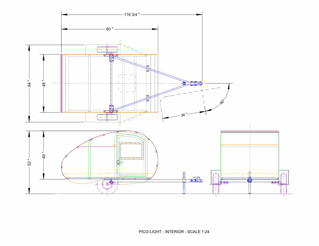
PICO-LIGHT - INTERIOR - SCALE 1:24
48 "
40 "
80 "52 "
64 "
36 "
80°
116 3/4 "

PICO-LIGHT - INTERIOR - SCALE 1:12
36 7/8 "
77 7/8 "

PICO-LIGHT - CHASSIS - SCALE 1:24
5" x 2" x 1/8" plate Body mount (x2)
2" x 1" x 14ga rect tube A-frame (x2)
2" x 2" x 11ga sq tube
Propstand socket (4" long)
1-1/2" x 1-1/2" x 14ga sq tube
Propstand (18" long) - locking
holes drilled at 1" intervals
2" x 1" x 14ga rect tube Axle tube
2" x 2" x 11ga sq tube Coupler mount
5-1/2" x 3-1/2" x 1/8"
plate Suspension mount (x2)
1-1/2" x 1/-1/2" x 1/8"
angle Body mount (x2)
425lb Flexiride half axle (x2)
4.80x8 wheel/tire (x2)
2" x 2" x 1/8" plate
Propstand foot
42 "
1/4" Propstand
locking pin
~ 12 "
PICO-LIGHT - CHASSIS - SCALE 1:12
19°
67 5/8 "
48 " inside angle flanges
56 "
9 1/2 "
6 "
70 "
46 " over A-frame tubes
Approx 77 1/2 " depending on coupler
48 1/4 " over axle tube
28 1/2 "

PICO-LIGHT - CHASSIS - SCALE 1:4
12 "
6 "
1/4 " axle tube to
mounting plate
5/8 " axle tube to
first bolt

PICO-LIGHT - CHASSIS - SCALE 1:12 (Details 1:2)
19 "
37 "
47 "
57 "
67 "
47 1/2 "
70 7/8 " (top surface of floor)
Cut ends of floorto angles shown afterframing is added
(1:2)
47°
51°
1x31x4
(preferably
oak or similar)
Floor 3/8" plywoodAll framing 1x2except as shown
Add 1/8" packing
where framing sits
on chassis rails
3 1/2 "
Sidewall measurement datum
1 3/8 "1 1/4 "
3/8" hold-down
bolts (x 8)

PICO-LIGHT - SIDEWALLS - SCALE 1:12 (Details 1:2)
4 1/2 "
22 1/2 "
44 1/2 "
70 "
5/8 " 3
/4 "
**
**
Note:Side and door skin 1/4" exterior plyAll framing 1x2.Framing marked ** can be madefrom two layers of 3/8" plywood.
Roof spar
Roof spar
Framing
as reqd
for latch
See geometry
for door opening
dimensions
Note: Mark all sidewall data (incl framingand internals) before cutting perimeter.
Measurement
datum point
(all dimensions
measured
to/from here)
Top surface
of floor
Optional edge
reinforcement
5 5/8 "
Underside
of floor
framing

PICO-LIGHT - DOOR OPENING DETAIL - SCALE 1:2
1/8
"
1/4" ply door skin
1x2 door framing
1x2 sidewall framing
3/8" ply floor
1x2 floor framing
1/4" ply sidewall skin
Alum T
moulding
provides
door stop
and seal
Do
or
op
en
ing
an
d d
oo
r s
ize
s
inc
rea
se
d b
y 1
/2"
all
rou
nd
Seal
Basic Door Opening as shown on Plans Alternative Door Opening using routered framing
Tranverse Section through Bottom of Sidewall
Optional 1"x1/4" ply
edge reinforcement

PICO-LIGHT - ROOF SPARS AND SHELF - SCALE 1:12 (Details 1:2)
12 "
12 "
12 "
15 1/2 "12 " 12 "
12 "
12 "
~12 "
Position
where profile
is vertical
9 7/8 "
Approx 25 7/8 "
Epoxy fillets (added
after roof skin is bonded)
1x3 spar (for skin joint)
1/4" ply
shelf
Note: Shelf cut and trial-fitted before roof skin fittedbut only fitted permanently after roof skin is bonded.
These spars positioned
to provide 14"x14" level
opening for optional roof vent

PICO-LIGHT - ROOF SKIN - SCALE 1:12 (Detail 1:2)
Perimeter of rearpanel approx 46-1/2"
Perimeter of frontpanel approx 89"
Perimeter of secondfront panel 19"
Front and rear roof skin panels
butt-jointed in middle of 1x3 roof spar
1/8" ply
roof skinSecond layer of 1/8" ply
to form stone guard
External framing to form flat
base for optional roof vent
14 "
17 "
1/4" ply sidewall
1/8" ply roof skin
Epoxy fillet
Wall-Roof Joint Detail 1:2

PICO-LIGHT - FENDERS - SCALE 1:6 (Detail 1:2)
1/4" bolts and
fender washers
Epoxy fillet or
fibreglass tape
3/8" ply
inner flange
1/4" ply
outer wall
1/8" ply skin (two
layers can be applied
if preferred)
2 "
Note: In order to maintain fender shape during assembly,consider leaving bottom of inner and outer walls
(say, down to zero datum line, as shown in blue dotted)in place until after skin is bonded on.
Confirm fender cutaway is
sufficient to allow wheel removal

PICO-LIGHT - PROFILE - SCALE 1:12
R75 7/8 "
R13 "
R24 "
R15 "
R224 "
13 "
56 "
14 1/2 "
16 5/8 "
20 1/2 "
44 1/2 "
80 "
64 1/8 " 31 3/8 "

PICO-LIGHT - PROFILE - SCALE 1:12
46 "
24 "
18 " 3 "
3 "
3 1
/2 "
7 1
/8 "
14 7
/8 "
20 "
35 "
38 "
47 "
48 1/2 "
12 "
3/4
"
4 1
/2 "
1/4
"
5 5
/8 "
Top surface
of floor
Note: Mark all sidewall items (incl framingand internals) before cutting perimeter.
Measurement
datum point
(all dimensions
measured
to/from here)

PICO-LIGHT - PROFILE - SCALE 1:12
4"
27 3/8 "
30 1/2 "
33 1/8 "
35 3/8 "
37 3/8 "
39 1/8 "
40 5/8 "
41 7/8 "
42 3/4 "
43 1/2 "
44 1/8 "
44 3/8 "
44 1/2 "
44 1/8 "
43 1/8 "
41 1/4 "
38 3/8 "
1 3/4 "
1/4 "
1/8 "
1 1/4 "
4 1/8 "
3 5/8 "
1 1/2 "
3/8 "
0 "
1/4 "
1 1/4 "
2 7/8 "
Note: Mark all sidewall items (incl framingand internals) before cutting perimeter.
Measurement
datum point
(all dimensions
measured
to/from here)

PICO-LIGHT - PROFILE - SCALE 1:12
4"5 1/8 "
2 1/2 "
1 1/2 "
1 1/8 "
3/4 "
4 1/2 "
1/4 "
3/8 "
3/4 "
1 1/8 "
1 1/2 "
2 1/8 "
3 7/8 "
20 "
35 "
47 "
Note: Mark all sidewall items (incl framingand internals) before cutting perimeter.
Measurement
datum point
(all dimensions
measured
to/from here)

PICO-LIGHT - PROFILE - SCALE 1:4
3/4 "
6 1/4 "
9 3/8 "
11 1/8 "
11 7/8 "
12 "
11 7/8 "
10 1/2 "
6 3/4 "
4"

PICO-LIGHT - PROFILE - SCALE 1:4
3/4 "
2 7/8 "
4 1/2 "
5 1/2 "
6 "
5 7/8 "
4 5/8 "
1/4 "
3 "
20 "
35 "
38 "
47 "
48 1/2 "
49 "

PICO-LIGHT WEIGHT ESTIMATE
Note: Zero datum for LCG and Moment measurement is CAD zero - rear end of body
Weight LCG Moment Weight LCG Moment
total from rear total total from rear total
Summary lb in lb-in Optional Items lb in lb-in
CHASSIS
Frame 35 2385 Aluminium skin 43 2024
Components 60 2775 Margin (sealant, fasteners) 10% 4 202
Subtotal 94 54.9 5159 47 2226
Margin (paint, weld, fasteners) 5% 5 258
Total 99 5417 Foam insulation (top & sides) 11 502
Margin (glue, fabric) 10% 1 50
BODY 12 553
Floor 41 1631
Sides 30 1400 11ga frame tubes 9.9 642
Doors 12 669 Margin (paint, weld, fasteners) 5% 0 32
Roof 34 1482 10 674
Shelf 10 300
Fenders 9 342 Sidewall edge reinforcement 0.7 26
Subtotal 136 42.9 5823 Margin (glue, fasteners) 5% 0 1
Margin (paint, glue, 5% 7 291 1 27
fasteners, minor fittings) 142 6114
FITTINGS
Body Fittings 18 913
Fit-out Items 22 896
Subtotal 40 45.2 1809
Margin (growth) 10% 4 181
44 1990
Optional items 0 0
Unladen Weight 281 47.5 13340
Longl position of wheels 38.0
Longl position of hitch 115.5
%age of weight on hitch 12.2%
Weight on hitch 34
Weight on axle 247

WEIGHT ESTIMATE DETAIL CALCS
CHASSIS Spec No Units Qty Unit Wt Wt each Weight LCG, inch Moment
units lb/unit lb lb from rear lb-in
Frame
Axle cross-member 2"x1"x14ga 1 in 48 0.1333 6.4 6.4 41.5 266
A-frame 2"x1"x14ga 2 in 66 0.1333 8.8 17.6 73.3 1290
Coupler mount 2"x2"x11ga 1 in 10 0.2450 2.5 2.5 107.5 263
Sidewall mounts 1.5"x1.5"x1/8" angle 2 in 12 0.1025 1.2 2.5 41 101
Axle mounting plates 1/8" plate 2 in2 19.25 0.0354 0.7 1.4 41.5 57
Front mounting plate 1/8" plate 2 in2 10 0.0354 0.4 0.7 71.5 51
Propstand socket 2"x2"x11ga 1 in 4 0.2450 1.0 1.0 101.5 99
Propstand tube 1.5"x1.5"x14ga 1 in 18 0.1333 2.4 2.4 101.5 244
Propstand foot 1/8" plate 1 in2 4 0.0354 0.1 0.1 101.5 14
Note: 11ga = 0.120", 14ga = 0.083" 34.5 2385
Components
Wheels/tyres 4.80x8, B, 4x4 2 ea 11.0 22.0 38 836
Half-axles Flexiride 425lb, pair 1 pr 13.0 13.0 40.5 527
Hubs 4x4 2 ea 9.0 18.0 38 684
Coupler Straight tongue 1 ea 4.5 4.5 112 504
Safety chains est 2 ea 1.0 2.0 112 224
59.5 2775
BODY
Floor
Plywood 3/8" ply 1 in2 3344 0.00881 29.5 29.5 38.9 1146
Trans frame rear ex 1x3 1 in 47.5 0.02799 1.3 1.3 5.1 7
Trans frames mid 1x2 4 in 44.5 0.02441 1.1 4.3 44.3 193
Trans frame front ex 1x4 1 in 47.5 0.04752 2.3 2.3 73 165
Side frames 1x2 2 in 64.5 0.02441 1.6 3.1 38.3 121
40.6 1631
Sides
Side (excl door) 1/4" ply 2 in2 1949 0.00588 11.5 22.9 44.3 1015
Rear intermed frame 1x2 2 in 31.0 0.02441 0.8 1.5 23.3 35
Rear door frame 1x2 2 in 38.0 0.02441 0.9 1.9 45.3 84
Door corner frame 1x2 2 in 4.1 0.02441 0.1 0.2 47.3 9
Bottom door frame 1x2 2 in 21.3 0.02441 0.5 1.0 59.3 62
Top door frame 2@3/8 ply 2 in2 37.9 0.01763 0.7 1.3 58.5 78
Front door frame 1x2 2 in 33.8 0.02441 0.8 1.7 70.8 117
30.5 1400

Doors
Door 1/4" ply 2 in 577 0.00588 3.4 6.8 56.6 384
Rear door frame 1x2 2 in 29.1 0.02441 0.7 1.4 46.9 67
Lock block 1x2 2 in 5.0 0.02441 0.1 0.2 48.3 12
Door corner frame 1x2 2 in 3.9 0.02441 0.1 0.2 38.1 7
Bottom door frame 1x2 2 in 19.7 0.02441 0.5 1.0 59.3 57
Top door frame 2@3/8 ply 2 in2 23.5 0.01763 0.4 0.8 58.5 48
Front door frame 1x2 2 in 27.8 0.02441 0.7 1.4 69.1 94
11.8 669
Roof
Roof skin 1/8" ply 1 in2 6475 0.00294 19.0 19.0 46 875
Stone guard 1/8" ply 1 in2 960 0.00294 2.8 2.8 38 107
Spars 1x2 9 in 47.5 0.02441 1.2 10.4 43.4 453
Joining spar 1x3 1 in 47.5 0.04069 1.9 1.9 24.3 47
34.2 1482
Shelf
Shelf 1/4" ply 1 in2 1444 0.00588 8.5 8.5 29.3 249
Front frame 1x2 1 in 47.5 0.02441 1.2 1.2 44.1 51
9.6 300
Fenders
Skin 1/8" ply 2 in2 328 0.00294 1.0 1.9 38 73
Inner side 3/8" ply 2 in2 74 0.00881 0.7 1.3 39 51
Outer side 1/4" ply 2 in2 147 0.00588 0.9 1.7 38 66
Sundries 2 2.0 4.0 38 152
9.0 342
FITTINGS
Body Fittings
Windows est 2 ea 4.0 8.0 58 464
Door hinge est 2 ea 0.5 1.0 70 70
Door lock/handle est 2 ea 1.0 2.0 49 98
Door trim/seal est 2 ea 1.0 2.0 58 116
Taillights est 2 ea 0.5 1.0 0 0
License plate est 1 ea 1.0 1.0 0 0
Wiring est 1 ea 3.0 3.0 55 165
18.0 913
Fit-out Items
Mattress est 1 ea 20.0 20.0 39 780
Curtains/blinds est 2 ea 1.0 2.0 58 116
22.0 896

OPTIONAL
Aluminium skin
Sides .032" Alum 2 in2 2526 0.00312 7.9 15.8 47.1 742
Roof .032" Alum 1 in2 6475 0.00312 20.2 20.2 46 929
Edge trim 1x1/2 2 in2 176 0.02 3.5 7.0 50 352
43.0 2024
Foam insulation
Sides 3/4" foam 2 in2 2526 0.00094 2.4 4.7 47.1 223
Roof 3/4" foam 1 in2 6475 0.00094 6.1 6.1 46 279
10.8 502
11ga frame tubes
Axle cross-member deduct 2"x1"x14ga 1 in 48 -0.1333 -6.4 -6.4 41.5 -266
add 2"x1"x11ga 1 in 48 0.1883 9.0 9.0 41.5 375
A-frame deduct 2"x1"x14ga 2 in 66 -0.1333 -8.8 -17.6 73.3 -1290
add 2"x1"x11ga 2 in 66 0.1883 12.4 24.9 73.3 1822
9.9 642
Sidewall edge reinforcement
Front reinf. 1/4" ply 2 in2 28.9 0.00588 0.2 0.3 57 19
Rear reinf. 1/4" ply 2 in2 28.5 0.00588 0.2 0.3 19 6
0.7 26
Side Areas
A x Ax
Side, complete 2742 48 131616
Door cutout 793 57 45201
Side excl door cutout 1949 44.3 86415
Door cutout 793 57 45201
Window cutout 216 58 12528
Door excl window cutout 577 56.6 32673
Side, complete 2742 48 131616
Window cutout 216 58 12528
Side excl window cutout 2526 47.1 119088