
The Physics of Siege Weapons STEM Club Resource Pack · PDF fileThe Trebuchet: The Trebuchet...
23
With support from Oxfordshire County Council, Science Oxford is pleased to present; Catapult Engineering The Physics of Siege Weapons STEM Club Resource Pack
Transcript of The Physics of Siege Weapons STEM Club Resource Pack · PDF fileThe Trebuchet: The Trebuchet...

With support from Oxfordshire County Council,
Science Oxford is pleased to present;
Catapult Engineering
The Physics of Siege Weapons
STEM Club Resource Pack

Introduction:
Catapult engineering involves using stored energy to hurl
a projectile without using any explosives. The stored
energy comes from building mechanisms that use tension,
torque and gravity.
The main types of catapult are the trebuchet and the
Mangonel.
In this project you will be building and test different siege
weapons, discovering the mechanisms that make them
work and how to improve them, before building your
own, ultimate siege weapon.
*"Trebuchet". Licensed under Creative Commons Attribution-Share Alike 3.0 via Wikimedia Commons -
http://commons.wikimedia.org/wiki/File:Trebuchet.jpg#mediaviewer/File:Trebuchet.jpg
*"Replica catapult". Licensed under Creative Commons Attribution-Share Alike 3.0 via Wikimedia Commons -
http://commons.wikimedia.org/wiki/File:Replica_catapult.jpg#mediaviewer/File:Replica_catapult.jpg
A Trebuchet* A Mangonel*

The Mangonel:
The Mangonel is probably the most familiar looking type of catapult. It involves
stretching or winding up a long piece of rope attached directly (or indirectly) to a
throwing arm, therefore putting it under tension. When released, the rope will want
to return to its relaxed length and will therefore create a pulling force in the opposite
direction, pulling on whatever object it is attached to. Tension is effectively the
opposite of compression.
The angle at which the throwing arm is pulled back to will affect both the distance
the projectile will travel and also the height that it reaches when in the air.
Rope Throwing arm
Restraining Rope
Frame
The restraining rope is released
and the previously strained and
taught rope pulls back to its
original position

The Trebuchet:
The Trebuchet was one of the more accurate and efficient types of catapult used in
ancient times.
It worked by using the energy of a falling counterweight to rotate a beam around a
pivot resulting in the release of whatever projectile was loaded into the sling at the
other end of the beam.
Counter weight
Beam
Pivot point
Sling
As the counterweight drops
downwards the beam swings
round and launches the attached
sling into the air

Suggested Timetable:
Stage 1: Introduction to Catapult Engineering
Introduction to Siege Weapons and the engineering behind
them
Stage 2: Initial Investigations (resource sheets)
Investigate the components that make the best catapult
Stage 3: Planning and Design (resource sheets)
Start to plan and design your own Weapon
Stage 4: Construction
Start Building!
Stage 5: Testing
Test your design to see what works
Stage 6: Modification
Make changes to your design to make it even better!
Stage 7: Demonstration and Competition
Show off your catapult and put it to the test!

Stage 2: Initial Investigations
Investigating Launch Angles
In this investigation you will be exploring the effect the launch angle has on the
distance a projectile (ball) travels. To do this you will be using the ‘Xpult’ catapult
shown below. The ‘Xpult’ catapult operates similarly to a modern day mangonel; a
rubber band stores elastic potential energy as it is stretched, which is released as
kinetic energy when it is released.
Equipment needed:
‘Xpult’ Catapult Tape measure
Pen Target (optional)
Paper
What to do: ‘Xpult’ Catapult kit:
Catapult itself including a locking pin
Three rubber bands
A table tennis ball and a small white plastic
perforated ball.
A clamp for attaching the catapult to the
table
Set up the catapult as show below:
Unfold the catapult by removing the locking pin and swinging the aluminium
launch lever all the way round to the other side of the black plastic base.
Clamp the black base to the edge of a table.
Thread a rubber band through the large hole in the aluminium disc, and hook it
onto the designated hooks each side of the aluminium lever.
Re-insert the pin into one of the holes, for now anywhere between 30-60⁰ Set up a tape measure from the base of your catapult all the way across the
room, covering at least 3 metres.
If your tables don’t stretch 3 metres, you can always place the tape measure on the
floor
Pull-back angle read
here
Launch angle read here
Clamp
Locking pin
Rubber band

Allocate roles within your group (although you can swap around so that everybody
gets a turn and everything):
A spotter- this person is in charge of determining the exact landing location of
the ball
A shooter- this person operates the catapult
An Analyst- this person is in charge of entering the data into the table correctly
Initial tests- to understand the relationship between the launch angle and the pull-
back angle
Set the launch angle to 45⁰ (note that you read the launch angle at the bottom
edge of the black plastic base). You can experiment with different launch angles
later, but for now start with 45⁰
Start with a pull-back angle of 20⁰, the white perforated ball and just one rubber
band.
Launch the ball three times, and record each distance.
Calculate the median of the distances, this is just the middle distance (not the
smallest or the largest, the one in between)
Calculate the range of the distances- this is the difference between the furthest
shot and the nearest shot (biggest number-smallest number)
Now move the pull-back angle by 10⁰, so you go to 30⁰ and repeat the
experiment three times. Continue to increase the pull-back angle in increments of 10⁰ until you have
reached a pull-back angle of 90⁰ or higher. The ball has a tendency to fall out of
the cup if you pull the catapult arm too far back.
Continue to calculate the median and range for each different pull-back angle
and fill in the table below.
Experiment 1 Launch angle = 45⁰ Number of rubber bands = 1
Pull-back angle
(⁰) Shot 1 (cm) Shot 2 (cm) Shot 3 (cm) Median
(cm)
Range (cm)
Example 28 25 32 28 32-25=7
10
20
30
40
50
60
70
80
90
100
110
120

Analysing your data
One of the quickest ways to analyse data is to draw a graph. Put the pull-back
angle on the y-axis (vertical column) and the distance of the median shot (grey
column) on the x-axis (horizontal axis). Create your own or fill in the one below.
Another way to analyse your data is to look at the range column of your table. The
smaller your range, the more consistent your catapult was for that pull –back angle.
So the ‘best’ pull back- angle will be the angle at which the ball travelled the
furthest the most consistently, which can be determined by the row with the highest
median and the lowest range.
Further tests
From here you can experiment further to find the ‘best’ setting for your ‘Xpult’
catapult. You might decide that the best setting is the one that makes the ball go
the furthest distance, or you might decide that the best setting is the one that makes
the ball travel the highest up and over an object (you could set up a make shift wall)
or you might decide that the best setting is the one that makes the ball travel and hit
a target the most consistently.
Things to change:
The Launch angle
The number or rubber bands
Use the blank tables below or create your own.
Experiment 1 Launch angle = 45⁰ Number of rubber bands = 1
Pu
ll-b
ac
k a
ng
le (⁰)
12
0
11
0
10
0
90
80
70
60
50
40
30
20
10
0 20 40 60 80 100 12
0
14
0
16
0
180 20
0
22
0
24
0
26
0
28
0
30
0
32
0
34
0
Median distance ball travelled (cm)

Experiment 2 Launch angle = Number of rubber bands =
Pull-back angle (⁰)
Shot 1 (cm) Shot 2 (cm) Shot 3 (cm) Median
(cm)
Range (cm)
Example 28 25 32 28 32-25=7
10
20
30
40
50
60
70
80
90
100
110
120
Experiment 2 Launch angle = Number of rubber bands =
Pu
ll-b
ac
k a
ng
le (⁰)
12
0
11
0
10
0
90
80
70
60
50
40
30
20
10
0 20 40 60 80 100 12
0
14
0
16
0
180 20
0
22
0
24
0
26
0
28
0
30
0
32
0
34
0
Median distance ball travelled (cm)

Experiment 3 Launch angle = Number of rubber bands =
Pull-back angle (⁰)
Shot 1 (cm) Shot 2 (cm) Shot 3 (cm) Median
(cm)
Range (cm)
Example 28 25 32 28 32-25=7
10
20
30
40
50
60
70
80
90
100
110
120
Experiment 3 Launch angle = Number of rubber bands =
Pu
ll-b
ac
k a
ng
le (⁰)
12
0
11
0
10
0
90
80
70
60
50
40
30
20
10
0 20 40 60 80 100 12
0
14
0
16
0
180 20
0
22
0
24
0
26
0
28
0
30
0
32
0
34
0
Median distance ball travelled (cm)

Investigating counterweights and arm length
In this investigation you will be exploring the effect the arm length and the mass of
the counter weight has on the distance a projectile travels. To do this you will be
using K’nex to construct a trebuchet.
A trebuchet operates by using the energy of a falling counterweight to rotate a
throwing arm around a pivot point, resulting the in the release of a projectile
attached to the upper end of the throwing arm.
Equipment needed (per group):
Box of K’nex Tape measure
Pen Target (optional)
Paper String
Scissors Weights
Using K’nex K’nex comes in two types – rods and connectors. Rods
come in lots of different sizes, with the colour of the rod
corresponding to size (so all the yellow rods are the
same size, all the grey rods are the same size, etc.).
Connectors come in different shapes, with colour
corresponding to shape.
Rods and connectors connect together in one of three
different ways:
1) The top of a rod will click directly into the ‘teeth’ of
a connector, as below.
2) The teeth of the connector will bite into the body of
a rod
3) A rod can be threaded through the hole in the
centre of a connector

3D Structures
To make 3D shapes, the blue and purple connectors
need to be used. These connectors can be slotted
together – blue connector can connect to blue; or
purple to purple; or blue to purple, as below
These pieces can then be used to make strong 3D
shapes, for example the cube pictured below
However, from an engineering point of view, square and rectangular sides aren’t
very strong. By putting cross-braces in the sides, and turning the squares to two
triangles, it greatly increases the strength of the shape
Construct your Trebuchet
You can construct your trebuchet using a design of your own choice; however it will
need to have some basic principles
A Frame
A pivot point
A throwing arm
A counter weight
A sling attachment
Counter weight
Throwing Arm
Pivot point
Sling
Frame

Testing your trebuchet
The aim of this investigation is to look at the effect different arm lengths and counter
weights have on the distance your projectile travels.
Things to bear in mind
To start with you will need to test either
different arm lengths or different
counterweights- you will need to keep one
constant to start with!
If your counterweight is too heavy, the K’nex
will just break.
If Length A is longer than the height of the
frame, your throwing arm will not rotate
properly and will get stuck
If the length of string for your catapult is too
long, you will not get enough lift in your
throw
Allocate roles within your group (although you can swap around so that everybody
gets a turn and everything):
A spotter- this person is in charge of determining the exact landing location of
the projectile.
A shooter- this person operates the trebuchet.
An Analyst- this person is in charge of entering the data into the table correctly
Get Testing
Set up a tape measure from the base of your trebuchet all the way across the
room, covering at least 3 metres.
Start off with a constant counter weight and alter the arm length.
Launch your projectile three times, and record each distance
Calculate the median of the distances, this is just the middle distance (not the
smallest or the largest, the one in between)
Calculate the range of the distances- this is the difference between the furthest
shot and the nearest shot (biggest number-smallest number).
Now alter the arm length, you could make length A smaller than length B, the
same size as length B or bigger than length B.
Test again, when you have tried different combinations of arm lengths, you can
start changing the counter weight.
C

Analysing your data
One of the quickest ways to analyse data is to draw a graph. Put the arm length on
the y-axis (vertical axis) and the distance of the median shot (grey column) on the x-
axis (horizontal column). Create your own or fill in the one below. You can create
two separate lines for Length A and length B
Experiment 1 Counter weight mass =
Length A (cm) Length B
(cm)
Shot 1
(cm)
Shot 2
(cm)
Shot 3
(cm)
Median
(cm)
Range
(cm)
50cm
Example
50cm
Example
28 25 32 28 32-25=7
Experiment 1 Counter weight mass =
Arm
Le
ng
th (
cm
)
12
0
11
0
10
0
90
80
70
60
50
40
30
20
10
0 20 40 60 80 100 12
0
14
0
16
0
180 20
0
22
0
24
0
26
0
28
0
30
0
32
0
34
0
Median distance ball travelled (cm)
Length A = __________ Length B = ___________

Experiment 2 Length A = __________ Length B = ___________
Counter Weight (g) Shot 1 (cm) Shot 2 (cm) Shot 3 (cm) Median (cm) Range (cm)
100
Example
28 25 32 28 32-25=7
Experiment 2 Length A = ________ Length B = _____________
Co
un
ter
We
igh
t (g
)
60
0
55
0
50
0
45
0
40
0
35
0
30
0
25
0
20
0
15
0
10
0
50
0 20 40 60 80 100 12
0
14
0
16
0
180 20
0
22
0
24
0
26
0
28
0
30
0
32
0
34
0
Median distance ball travelled (cm)

Stage 3: Planning
Introduction to building your own catapult
It is time to decide which siege weapon you want to build: a Trebuchet or a
Mangonel
You will have the following equipment available:
Wooden dowel rounded assorted
thicknesses
Hammer
Wooden dowel square assorted
thicknesses
Hack saws
Wooden wheels Cutting Vice
Plywood sheeting Tape measure
Glue guns Awls
Wood glue Pliers
Carpet tacks Sandpaper
String Screw hooks
Screw eyes Material
Hand drill Wooden cogs
Trebuchet- initial planning
There are three main parts to a trebuchet:
A stable frame
A counterweight
The arm and sling mechanism
Stable frame
One of the simplest and strongest ways to make a stable frame is using an ‘A frame’ where you have two beams connecting at a 45⁰ angle.
The A- frames show below use a ratio of 1:1:1.5 for the lengths of wood.
1
1
1.5

Attach you A-frames together at the base; the
one pictured uses a piece of wood that is a ratio
of 0.4 compared to the first lengths of wood. You
can also decide to add a length of wood down
the middle to run your projectiles along.
Counter Weight
It is important to build a counterweight which will fit
inside your frame, with a gap either side; otherwise it will
get stuck when the arm swings. The counterweight does
not have to hinge or take on the form of a box, but it
does allow you to alter the weight.
Arm and Sling Mechanism
The arm should normally be the longest piece of wood in your trebuchet, make a
sling pouch and attach one end of it to the end of your throwing arm.
0.4
0.3
0.075
1.7
0.075
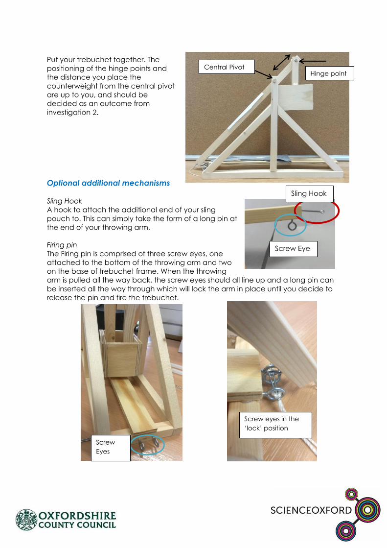
Put your trebuchet together. The
positioning of the hinge points and
the distance you place the
counterweight from the central pivot
are up to you, and should be
decided as an outcome from
investigation 2.
Optional additional mechanisms
Sling Hook
A hook to attach the additional end of your sling
pouch to. This can simply take the form of a long pin at
the end of your throwing arm.
Firing pin
The Firing pin is comprised of three screw eyes, one
attached to the bottom of the throwing arm and two
on the base of trebuchet frame. When the throwing
arm is pulled all the way back, the screw eyes should all line up and a long pin can
be inserted all the way through which will lock the arm in place until you decide to
release the pin and fire the trebuchet.
Sling Hook
Screw Eye
Screw
Eyes
Screw eyes in the
‘lock’ position
Central Pivot Hinge point

Mangonel- initial planning
There are 2 main parts to a mangonel:
A stable frame
A throwing arm and tension mechanism
Stable frame
One of the simplest and strongest ways to make a stable frame is using an ‘A frame’ where you have two beams connecting at a 45⁰ angle.
The A- frames show below use a ratio of 1:1:2.3 for the lengths of wood. The design
below also uses doweling in all the joints as well as glue for added strength and
stability. The overall height of the frame is a lot lower than that of a trebuchet- as
there is no counterweight mechanism to rotate through the frame.
1
1
2.3
1

Tensioning arms
1
1
0.5
Throwing arm and Tension mechanism
The mechanism for throwing a projectile is a bit more complicated than that of a
trebuchet. The following is adapted from a design created by Leonardo da Vinci. It
uses two ‘tensioning arms’ along with a ratchet (a gear that allows continuous
motion in one direction whilst preventing motion in the other direction) and a
winding mechanism.
A Ratchet is attached to a drum, which is free to rotate within the frame. By adding
a release arm one side of the frame, you create a mechanism that can be wound
up in one direction and locked in place until you are ready to release the tension.
The tensioning arms
shown here are
embedded into the
frame, in pre-cut slots in
the base. They are also
in a 1:1 ratio with the
length of the frame.
The release arm is in a
0.5:1 ratio with the
length of the base.
One of the tensioning
arms in centrally placed
the other one is off
centre- this allows room
for the throwing arm to
move through.
Ratchet
Release
Arm
Pivot Point
Fixed Joint
Drum
Pivot Point
Pivot Point

The throwing arm shown here is made from a long piece of doweling with a carved
wooden spoon on the end (pictured facing downwards). It is in a 1:1 ratio with the
length of the base. A swing arm stop has also been added. This prevents the
throwing arm from hitting the ground after launching and potentially breaking. String
has also been added to attach the tension arms to the drum mechanism. When the
drum is wound to the left, the throwing arm is pulled backwards into the launch
position and the tension arms are pulled tight and curved inwards (shown below.)
Firing Position
1
1
Throwing arm

Optional additional mechanisms
Firing mechanism
The Firing pin is comprised of two screw eyes and a piece of string, one screw eye is
attached to the bottom of the release arm and one is attached to the base of the
mangonel frame. Tie a piece of string around the first loop eye and then thread it
through the second screw eye. To release the throwing arm, pull sharply on the
string, which will dislodge the release arm from the ratchet and release the drum to
roll forwards releasing all the tension and firing the throwing arm forwards.
Release
Mechanism
Release Mechanism
Pull to release

Risk Assessment
2.
3.
4.
5.
What might be dangerous? Who might it be
dangerous for?
How we will make it safer.
1.
2.
3.
4.
5.
6.
Please Note: this sheet must be filled out before you start building


![Trebuchet versus Flinger: Millennial mechanics and bio ... · Harter - Trebuchet 3 1. Introduction The trebuchet or ingenium [1,2] was a super-catapult invented in China about 400BC](https://static.fdocuments.in/doc/165x107/5c61d37c09d3f2eb708b5d80/trebuchet-versus-flinger-millennial-mechanics-and-bio-harter-trebuchet.jpg)