The Physics of Sailing. Outline Hulls Keels Sails.
66
The Physics of Sailing
-
date post
22-Dec-2015 -
Category
Documents
-
view
222 -
download
3
Transcript of The Physics of Sailing. Outline Hulls Keels Sails.
The Physics of Sailing
Outline
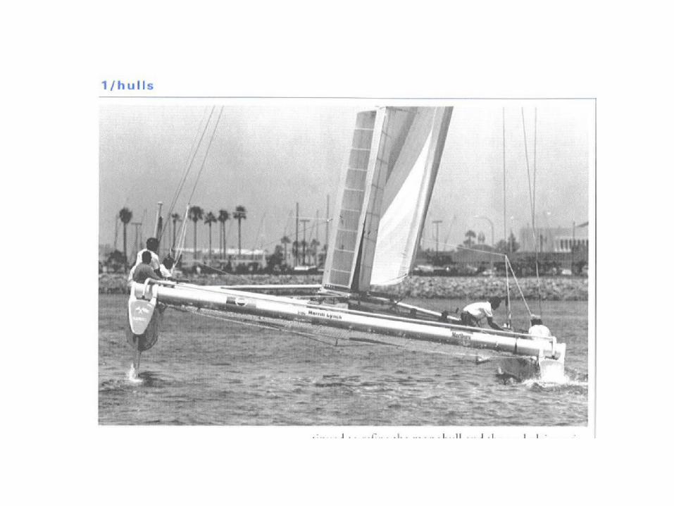
• Hulls
• Keels
• Sails
Hulls
• “Hull Speed”
• Resistance
• Shape
• Stability
Hull Speed
• Hull speed is determined by the length of the boat.
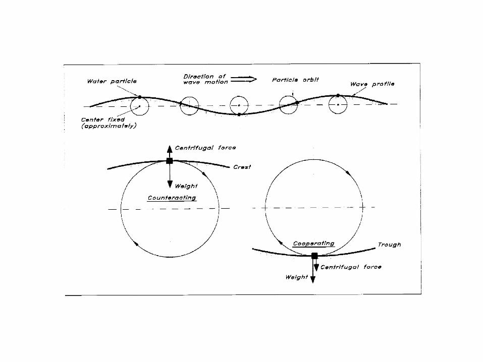
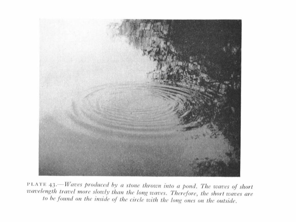
• Water waves are dispersive, i.e., their speeds depend on the wavelength of the wave; long wavelengths are faster.
• Boats generate a wave at the bow. The speed of this wave must equal the speed of the boat. (This is the speed with which the crest is being forced to advance.)
Hull Speed
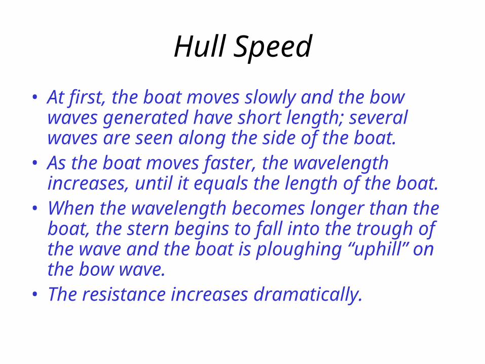
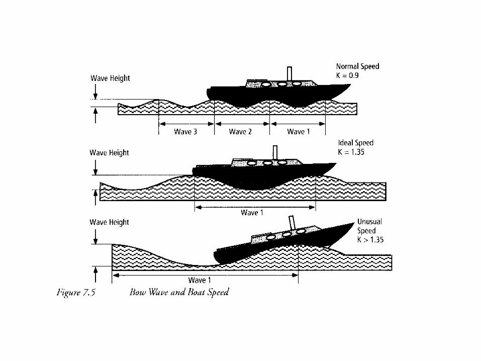
• At first, the boat moves slowly and the bow waves generated have short length; several waves are seen along the side of the boat.
• As the boat moves faster, the wavelength increases, until it equals the length of the boat.
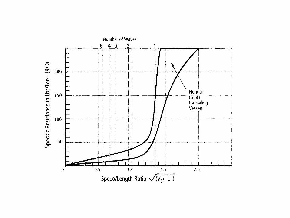
• When the wavelength becomes longer than the boat, the stern begins to fall into the trough of the wave and the boat is ploughing “uphill” on the bow wave.
• The resistance increases dramatically.
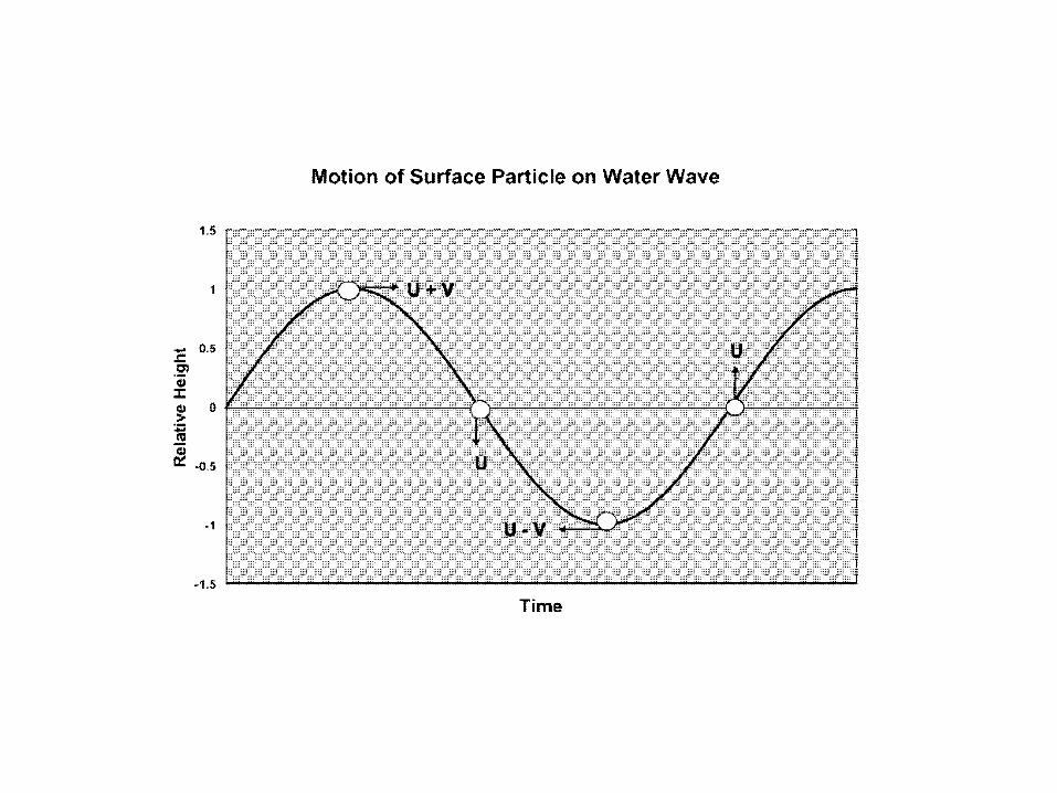
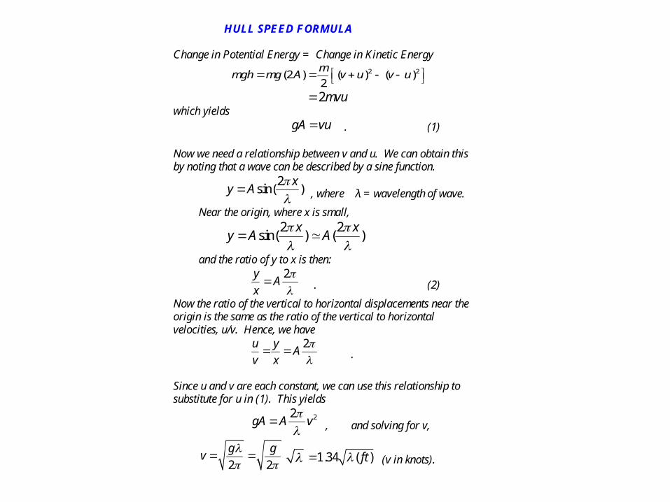
HULL SPEED FORMULA Change in Potential Energy = Change in Kinetic Energy
2 2(2 ) ( ) ( )
2
mmgh mg A v u v u
2mvu which yields
gA vu . (1) Now we need a relationship between v and u. We can obtain this by noting that a wave can be described by a sine function.
2sin( )
xy A
, where λ = wavelength of wave.
Near the origin, where x is small,
2 2
sin( ) ( )x x
y A A
and the ratio of y to x is then:
2y
Ax
. (2)
Now the ratio of the vertical to horizontal displacements near the origin is the same as the ratio of the vertical to horizontal velocities, u/v. Hence, we have
2u y
Av x
.
Since u and v are each constant, we can use this relationship to substitute for u in (1). This yields
22
gA A v
, and solving for v,
2 2
g gv
1.34 ( )ft (v in knots).
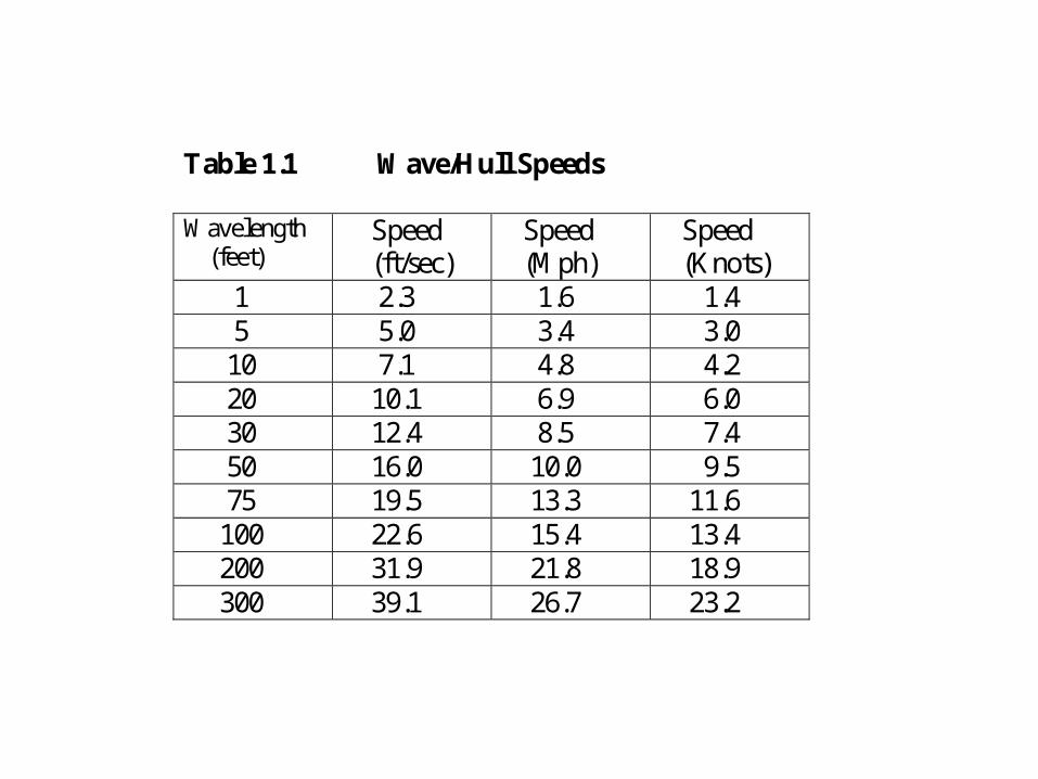
Table 1.1 Wave/Hull Speeds Wavelength (feet)
Speed (ft/sec)
Speed (Mph)
Speed (Knots)
1 2.3 1.6 1.4 5 5.0 3.4 3.0 10 7.1 4.8 4.2 20 10.1 6.9 6.0 30 12.4 8.5 7.4 50 16.0 10.0 9.5 75 19.5 13.3 11.6 100 22.6 15.4 13.4 200 31.9 21.8 18.9 300 39.1 26.7 23.2
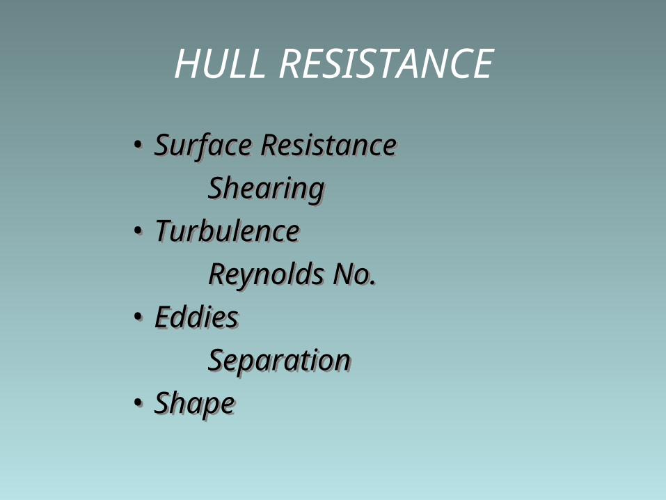
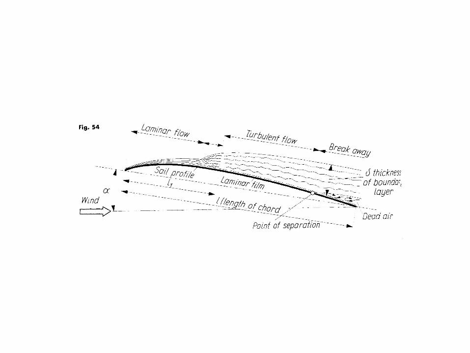
HULL RESISTANCE
• Surface Resistance
Shearing
• Turbulence
Reynolds No.
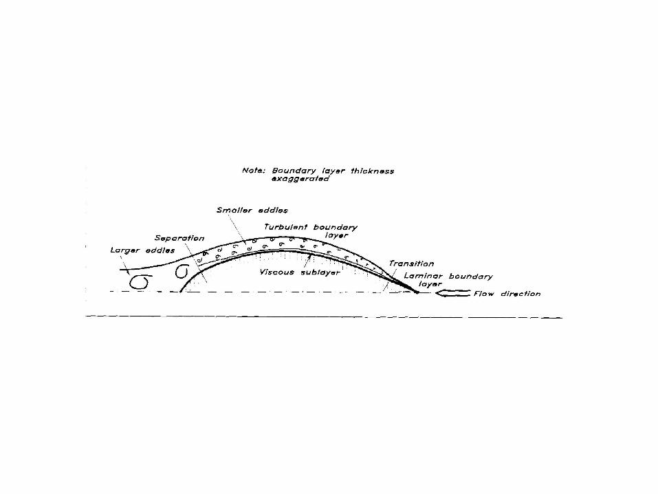
• Eddies
Separation
• Shape
• Surface Resistance
Shearing
• Turbulence
Reynolds No.
• Eddies
Separation
• Shape
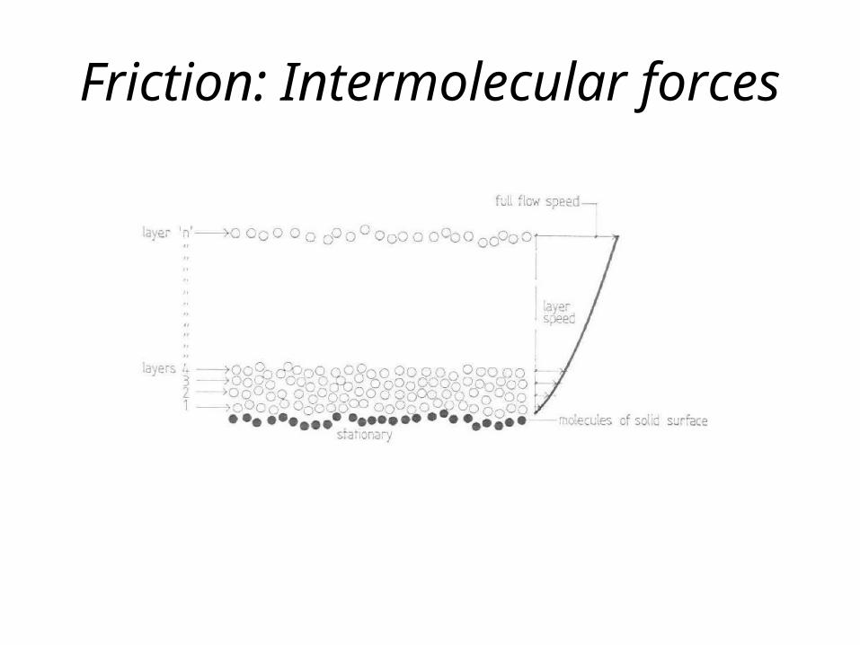
Friction: Intermolecular forces
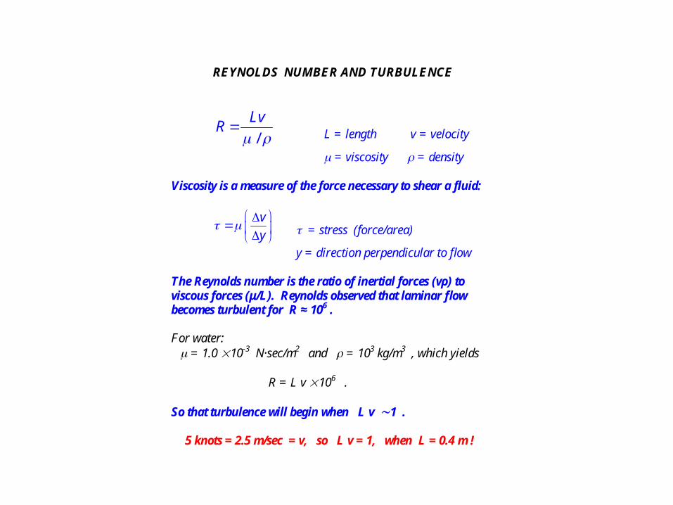
REYNOLDS NUMBER AND TURBULENCE
/
LvR
L = length v = velocity
= viscosity = density Viscosity is a measure of the force necessary to shear a fluid:
v
y
= stress (force/area)
y = direction perpendicular to flow
The Reynolds number is the ratio of inertial forces (vρ) to viscous forces (μ/L). Reynolds observed that laminar flow becomes turbulent for R ≈ 106 .
For water: = 1.0 10-3 N·sec/m2 and = 103 kg/m3 , which yields R = L v 106 . So that turbulence will begin when L v 1 .
5 knots = 2.5 m/sec = v, so L v = 1, when L = 0.4 m !
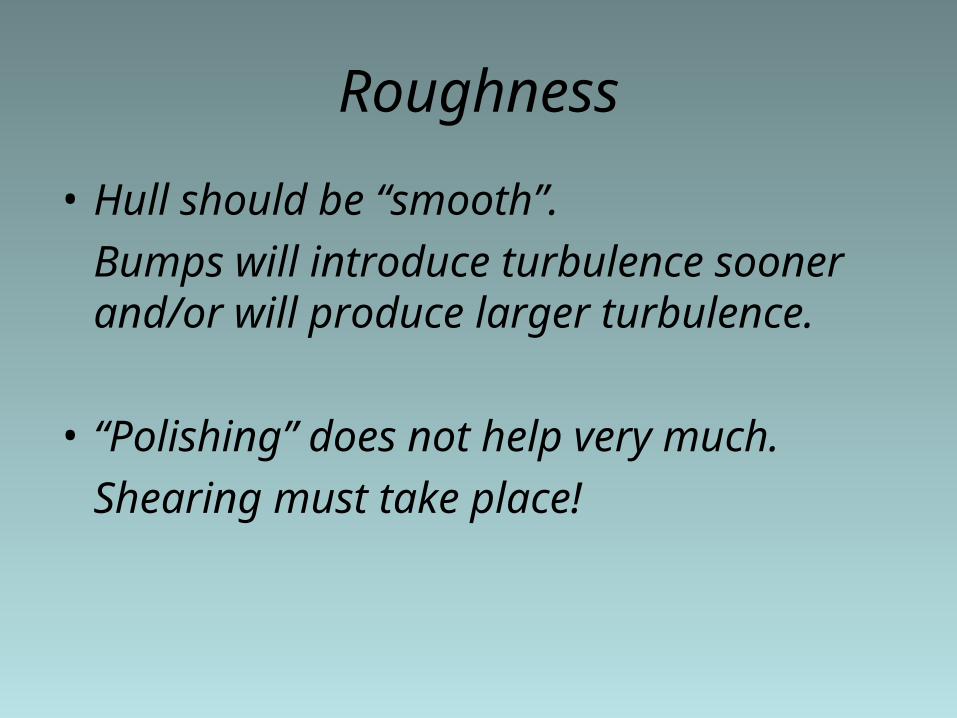
Roughness
• Hull should be “smooth”.
Bumps will introduce turbulence sooner and/or will produce larger turbulence.
• “Polishing” does not help very much.
Shearing must take place!
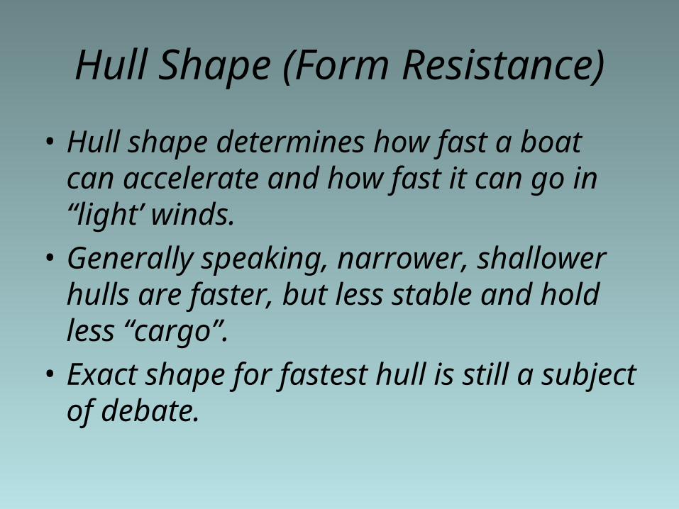
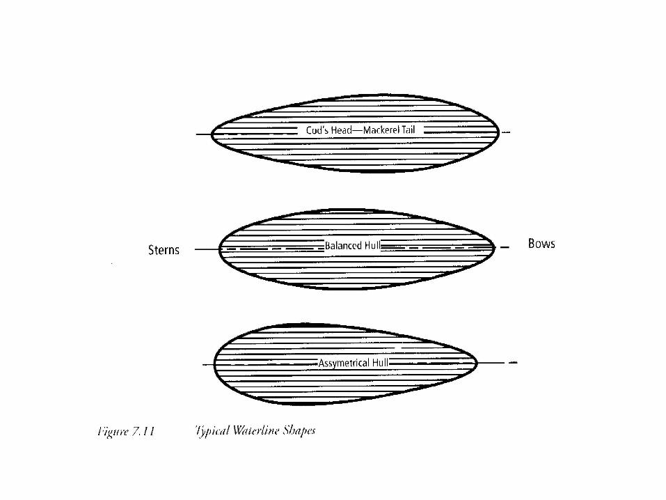
Hull Shape (Form Resistance)
• Hull shape determines how fast a boat can accelerate and how fast it can go in “light’ winds.
• Generally speaking, narrower, shallower hulls are faster, but less stable and hold less “cargo”.
• Exact shape for fastest hull is still a subject of debate.
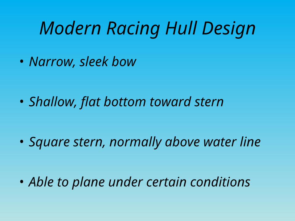
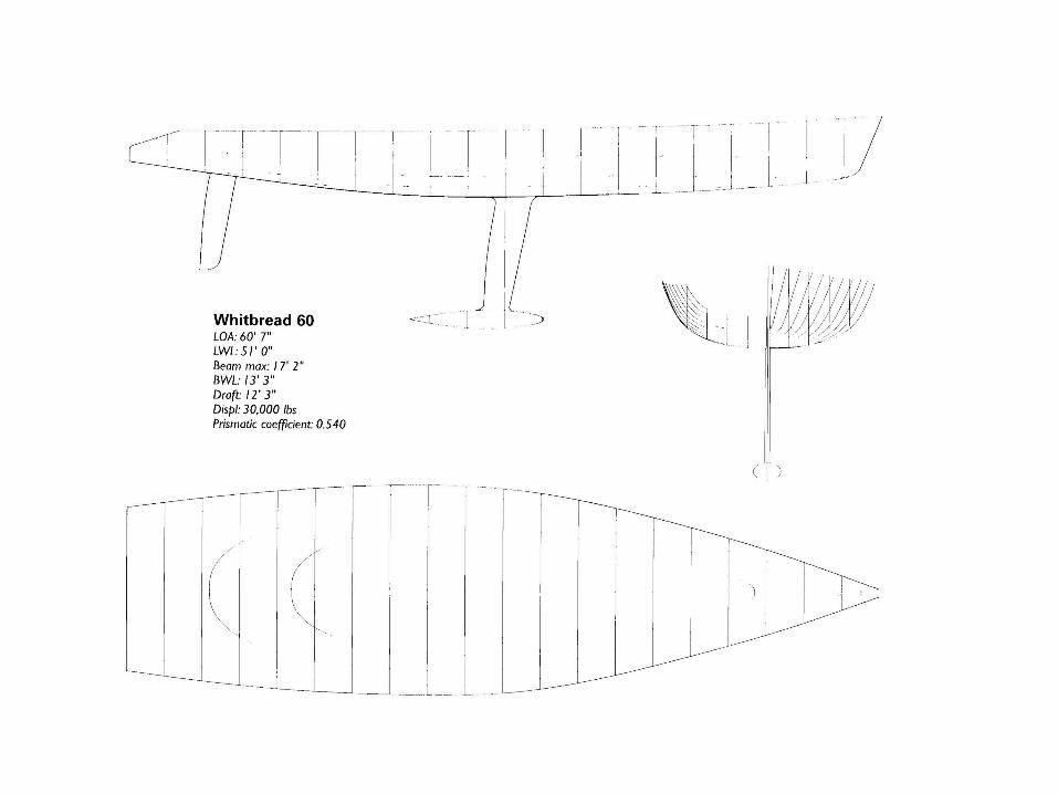
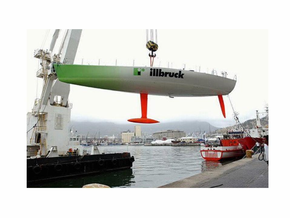
Modern Racing Hull Design
• Narrow, sleek bow
• Shallow, flat bottom toward stern
• Square stern, normally above water line
• Able to plane under certain conditions
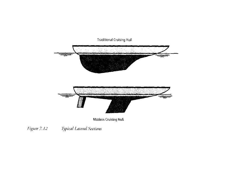
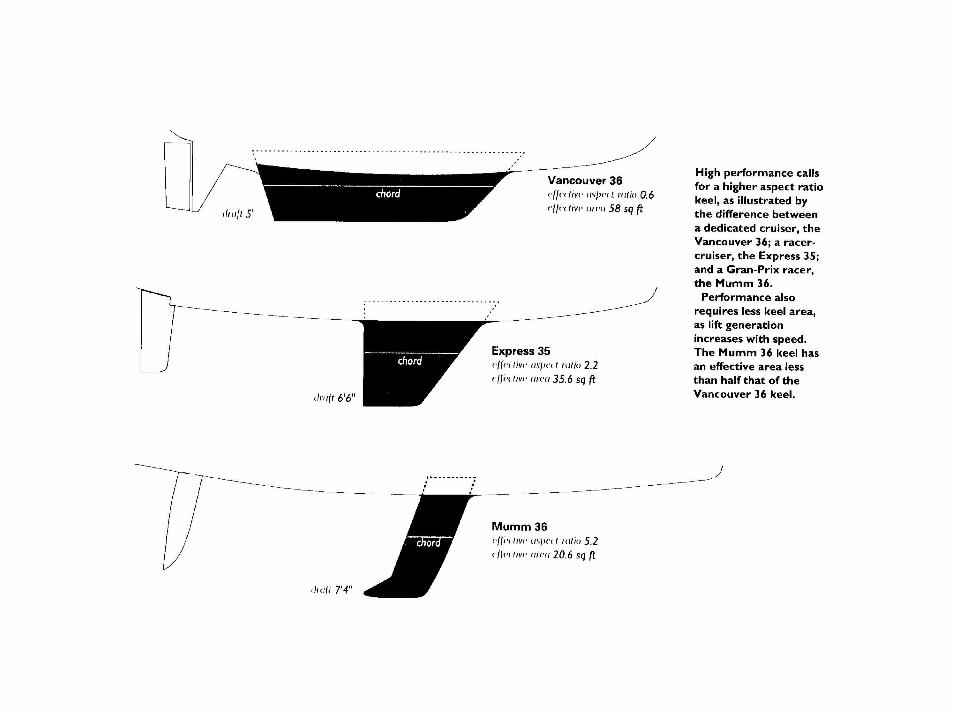
Keels
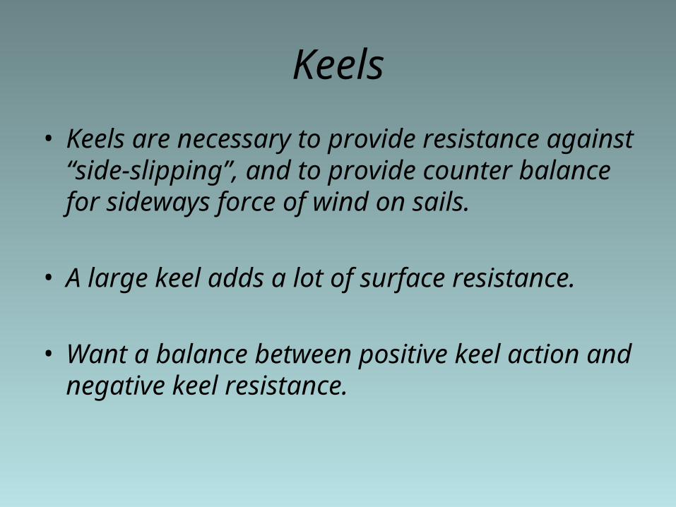
• Keels are necessary to provide resistance against “side-slipping”, and to provide counter balance for sideways force of wind on sails.
• A large keel adds a lot of surface resistance.
• Want a balance between positive keel action and negative keel resistance.
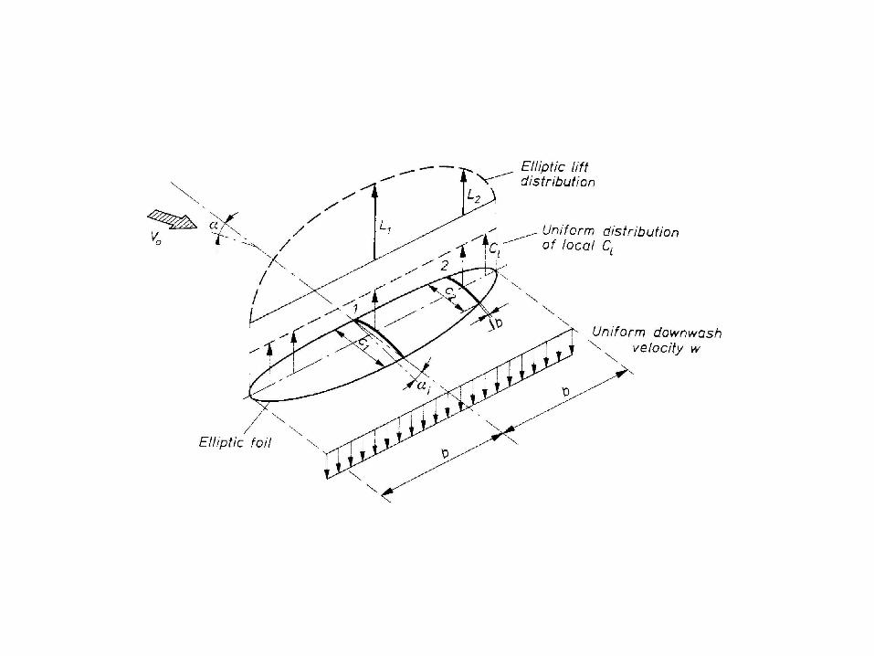
Wing theory
• Keels and sails act like airplane wings; i.e., they can provide “lift”.
• Proper design helps a lot!
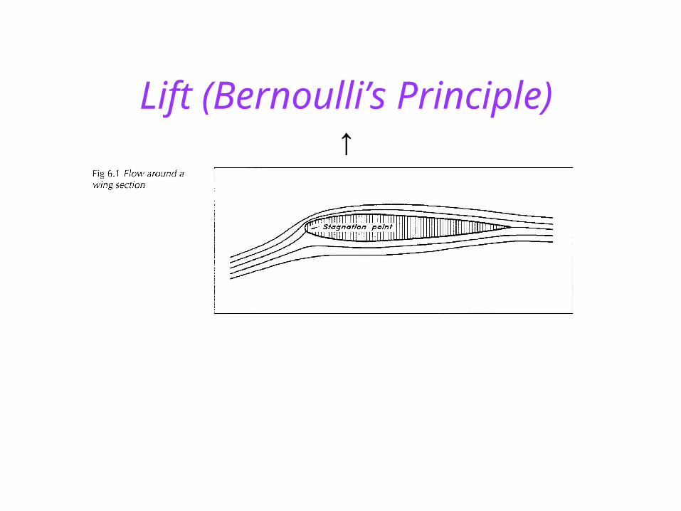
Lift (Bernoulli’s Principle)↑
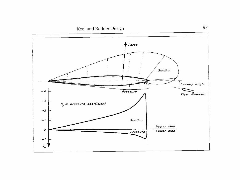
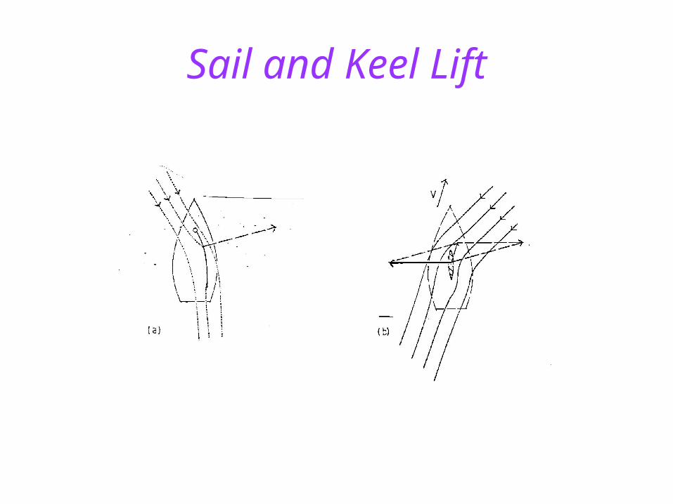
Sail and Keel Lift
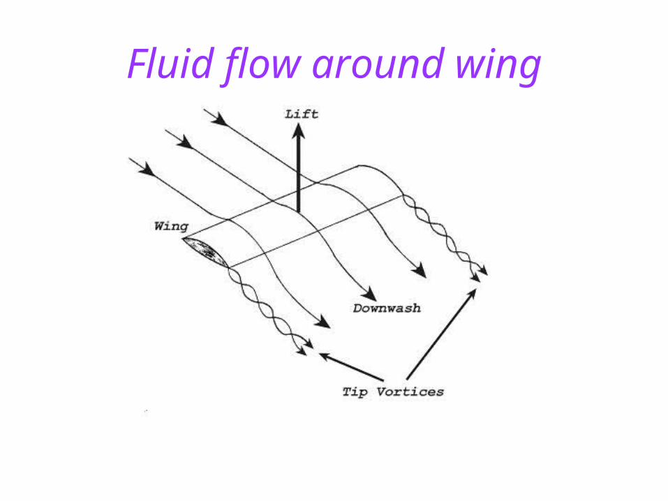
Fluid flow around wing
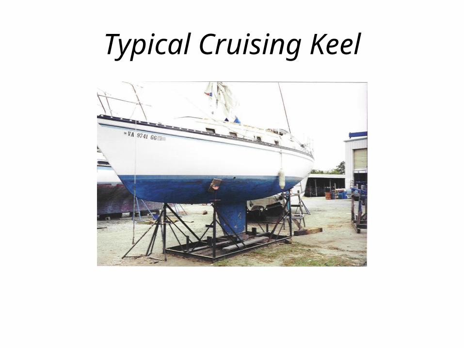
Typical Cruising Keel
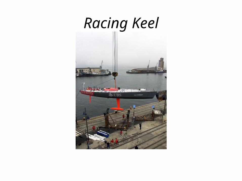
Racing Keel
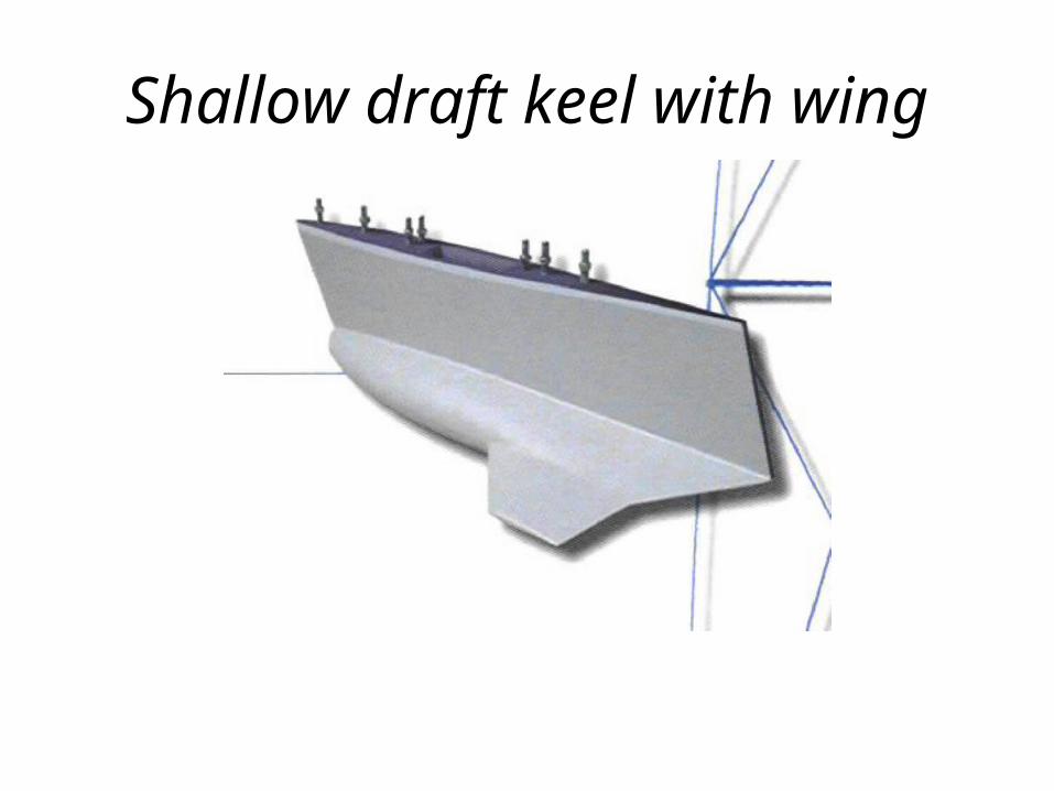
Shallow draft keel with wing
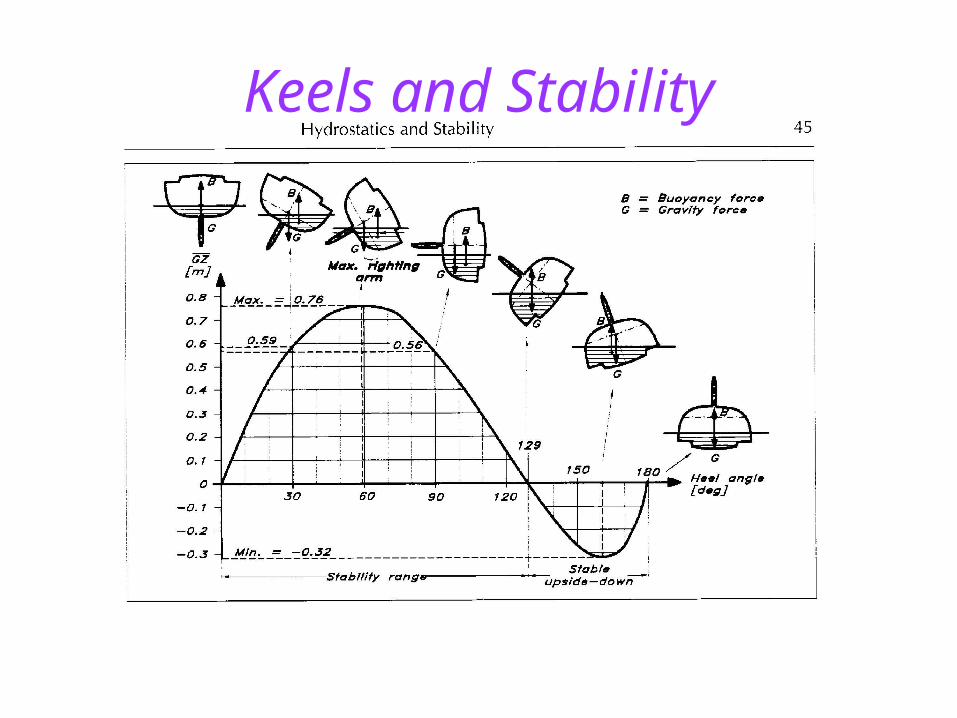
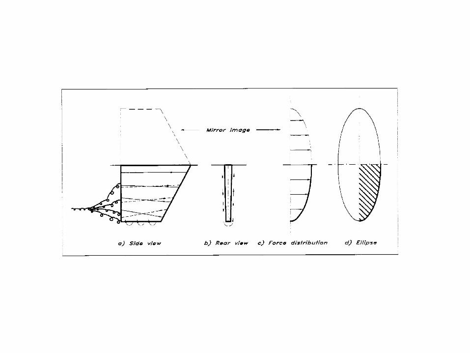
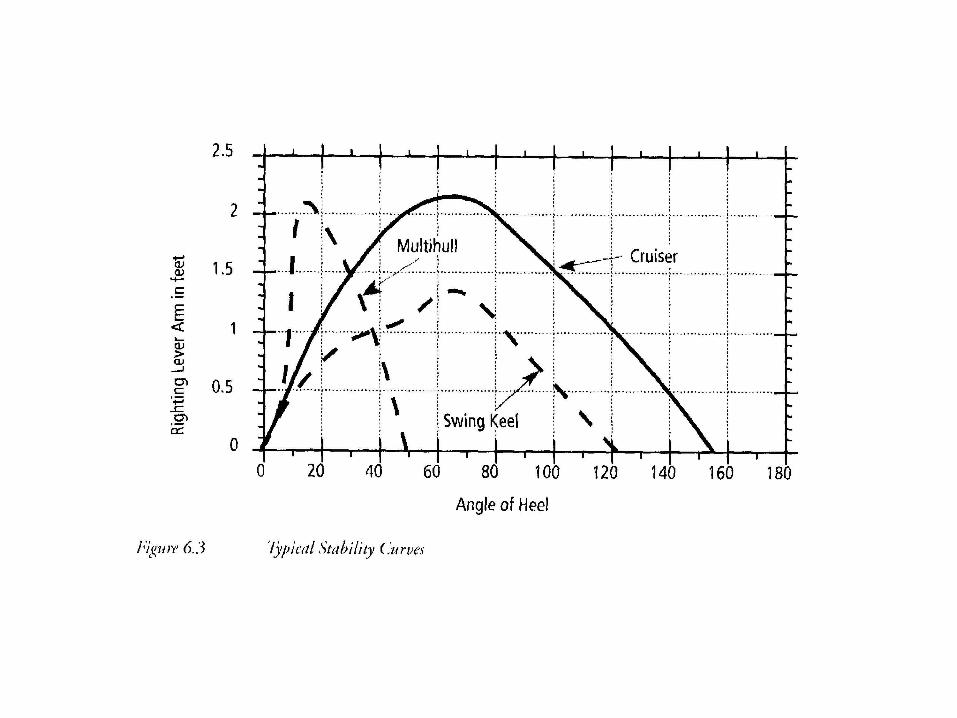
Keels and Stability
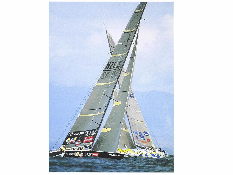
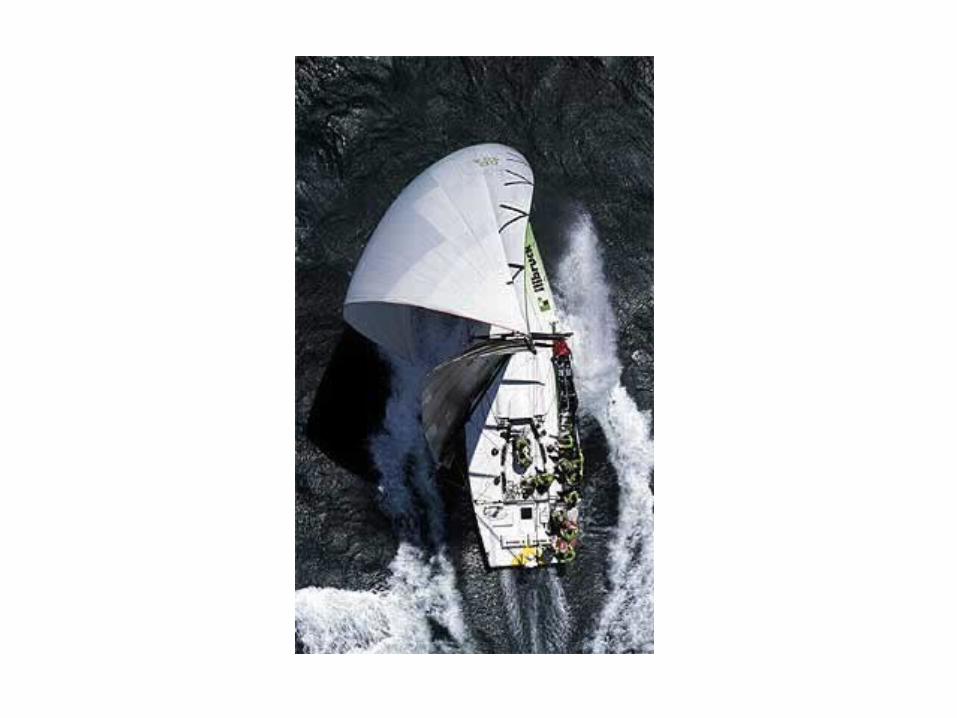
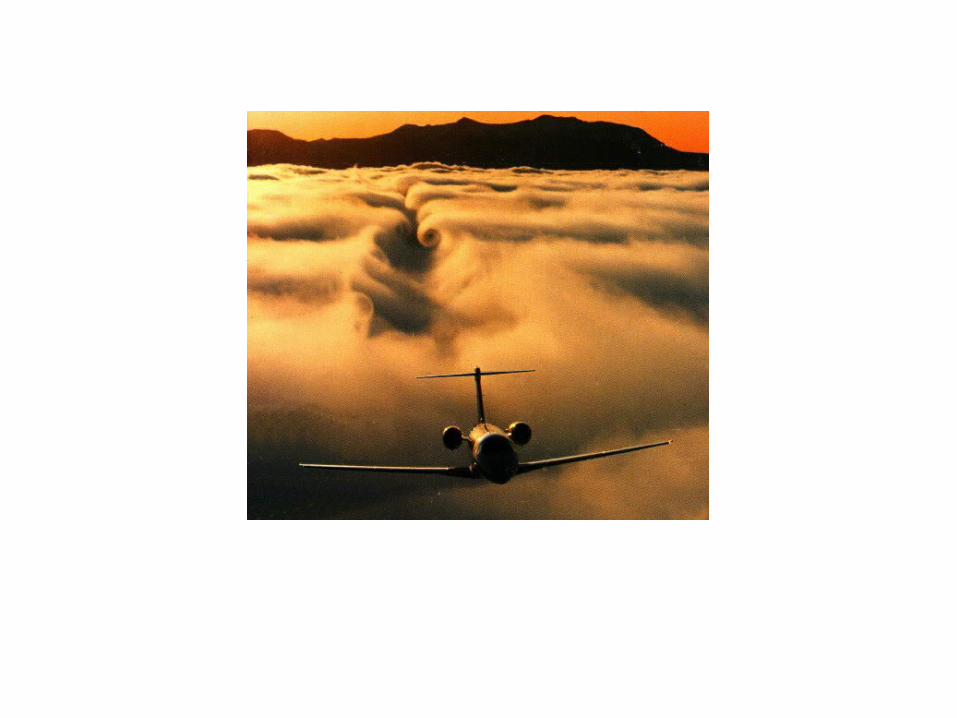
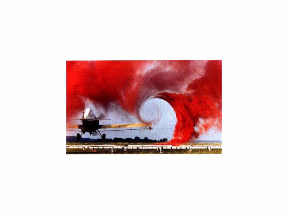
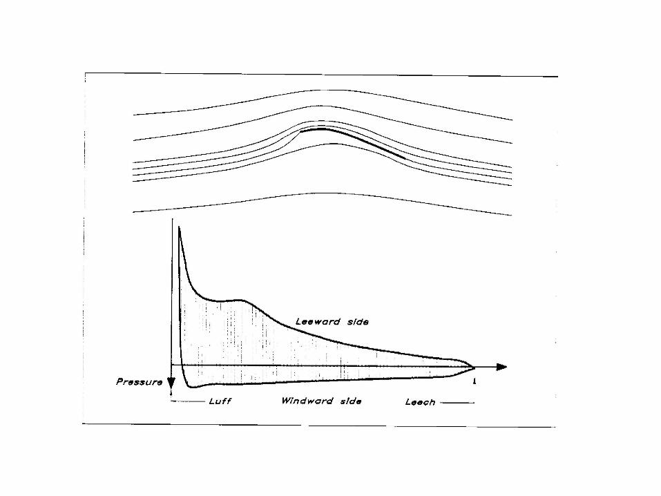
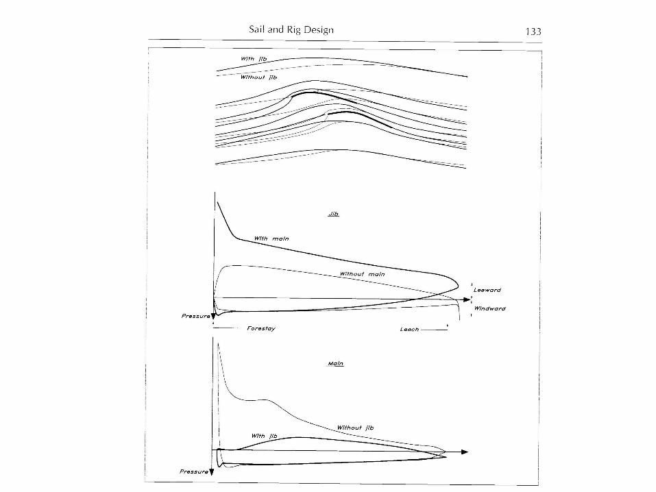
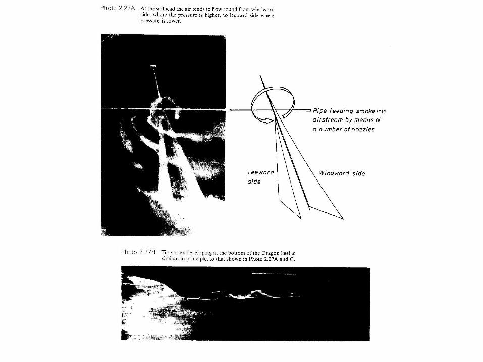
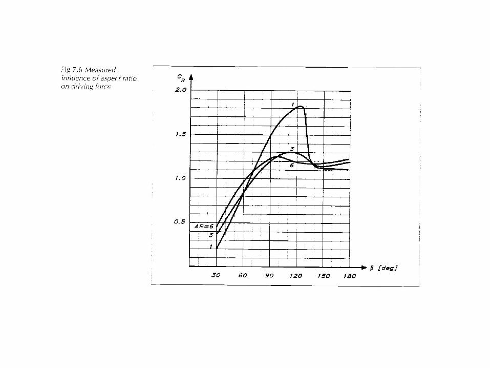
Sails
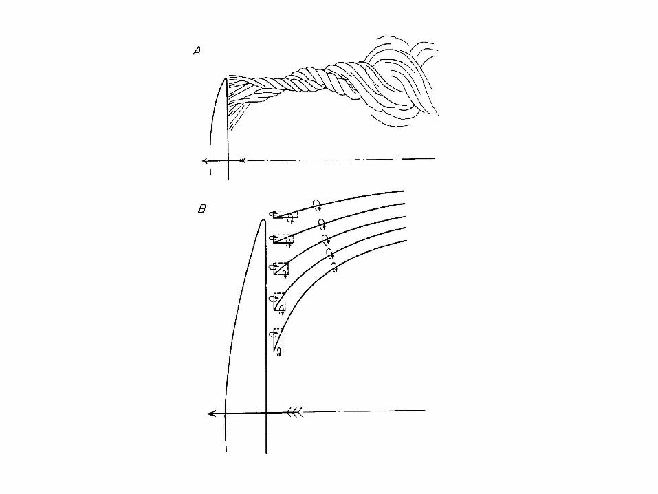
• Sails provide the power.• Sails act like wings and provide lift and
generate vortices.• Ideal sail shape is different for downwind
and upwind: Downwind sails should be square-shaped (low aspect ratio). Upwind sails should be tall (high aspect ratio) to minimize vortex generation.
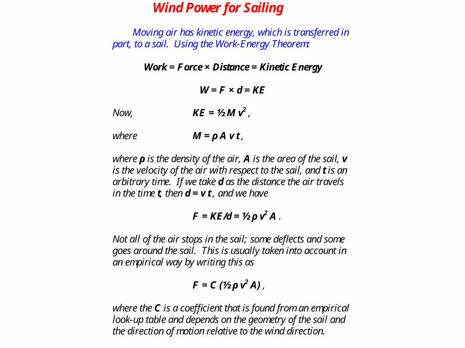
Wind Power for Sailing Moving air has kinetic energy, which is transferred in part, to a sail. Using the Work-Energy Theorem:
Work = Force × Distance = Kinetic Energy
W = F × d = KE
Now, KE = ½ M v2 , where M = ρ A v t , where ρ is the density of the air, A is the area of the sail, v is the velocity of the air with respect to the sail, and t is an arbitrary time. If we take d as the distance the air travels in the time t, then d = v t , and we have F = KE/d = ½ ρ v2 A . Not all of the air stops in the sail; some deflects and some goes around the sail. This is usually taken into account in an empirical way by writing this as F = C (½ ρ v2 A) , where the C is a coefficient that is found from an empirical look-up table and depends on the geometry of the sail and the direction of motion relative to the wind direction.
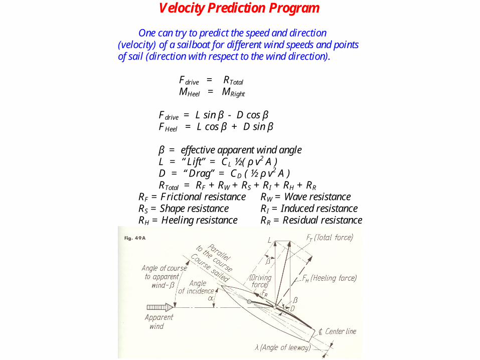
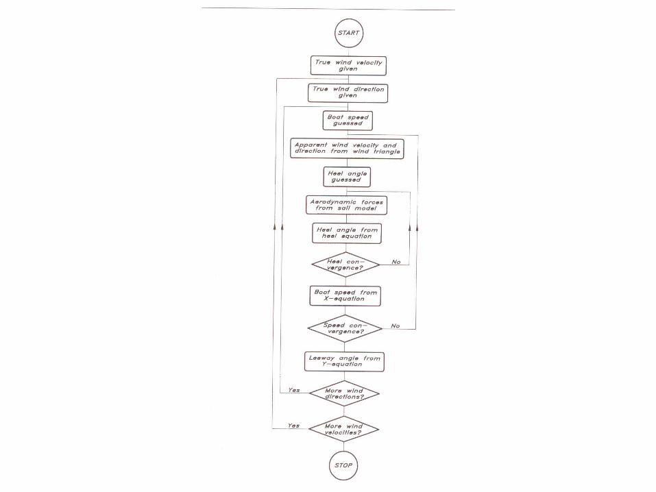
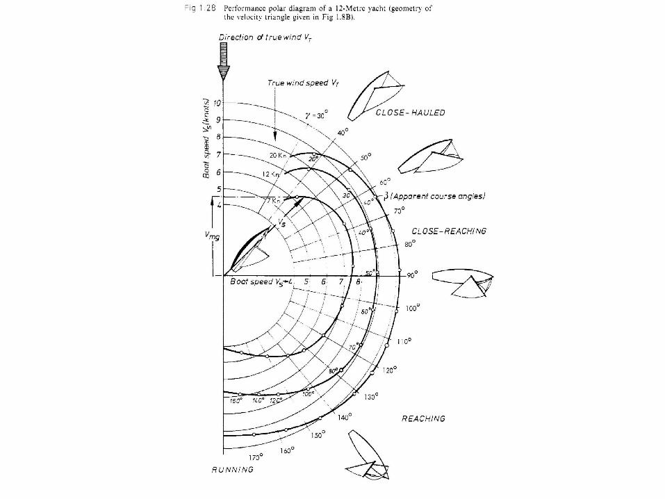
Velocity Prediction Program One can try to predict the speed and direction (velocity) of a sailboat for different wind speeds and points of sail (direction with respect to the wind direction). Fdrive = RTotal MHeel = MRight Fdrive = L sin β - D cos β FHeel = L cos β + D sin β β = effective apparent wind angle L = “Lift” = CL ½( ρ v2 A ) D = “Drag” = CD ( ½ ρ v2 A ) RTotal = RF + RW + RS + RI + RH + RR RF = Frictional resistance RW = Wave resistance RS = Shape resistance RI = Induced resistance RH = Heeling resistance RR = Residual resistance