The PanCam Instrument for the ExoMars Rover -...
32
ExoMars Rover Mission The PanCam Instrument for the ExoMars Rover A.J. Coates, 1,2 R. Jaumann, 3 A.D. Griffiths, 1,2 C.E. Leff, 1,2 N. Schmitz, 3 J.-L. Josset, 4 G. Paar, 5 M. Gunn, 6 E. Hauber, 3 C.R. Cousins, 7 R.E. Cross, 6 P. Grindrod, 2,8 J.C. Bridges, 9 M. Balme, 10 S. Gupta, 11 I.A. Crawford, 2,8 P. Irwin, 12 R. Stabbins, 1,2 D. Tirsch, 3 J.L. Vago, 13 T. Theodorou, 1,2 M. Caballo-Perucha, 5 G.R. Osinski, 14 and the PanCam Team Abstract The scientific objectives of the ExoMars rover are designed to answer several key questions in the search for life on Mars. In particular, the unique subsurface drill will address some of these, such as the possible existence and stability of subsurface organics. PanCam will establish the surface geological and morphological context for the mission, working in collaboration with other context instruments. Here, we describe the PanCam scientific objectives in geology, atmospheric science, and 3-D vision. We discuss the design of PanCam, which includes a stereo pair of Wide Angle Cameras (WACs), each of which has an 11-position filter wheel and a High Resolution Camera (HRC) for high-resolution investigations of rock texture at a distance. The cameras and electronics are housed in an optical bench that provides the mechanical interface to the rover mast and a planetary protection barrier. The electronic interface is via the PanCam Interface Unit (PIU), and power conditioning is via a DC-DC converter. PanCam also includes a calibration target mounted on the rover deck for radiometric calibration, fiducial markers for geometric calibration, and a rover inspection mirror. Key Words: Mars—ExoMars— Instrumentation—Geology—Atmosphere—Exobiology—Context. Astrobiology 17, 511–541. 1. Introduction P anCam is one of the context instruments on the ExoMars rover (Vago et al., 2017, in this issue) and will provide images in the visible and near infrared (NIR), from which crucial observations of landscape morphology, geology, and atmospheric science may be derived. PanCam will be the prime tool to characterize the morphology and geology of rock outcrops on the martian surface and will be crucial during mission operations for geological target selection and characterization. PanCam data will support the overarching exobiological objective of ExoMars through the character- ization of paleoenvironments that involved sustained liquid water at the ExoMars study site. The PanCam spectral range is extended by the Infrared Spectrometer for ExoMars (ISEM) instrument (Korablev et al., 2017, in this issue), which will add to the mineralogical determination; as shown by Harris et al. (2015), definitive identification of unique minerals is rarely achievable with the PanCam wavelength range alone. In addition, the Close-UP Imager (CLUPI; Josset et al., 2017, in this issue) will provide high-resolution images of potential drilling sites and other interesting 1 Mullard Space Science Laboratory, University College London, Dorking, UK. 2 Centre for Planetary Science at UCL/Birkbeck, London, UK. 3 Institute of Planetary Research, German Aerospace Centre (DLR), Berlin, Germany. 4 Space Exploration Institute, Neucha ˆtel, Switzerland. 5 Joanneum Research, Graz, Austria. 6 Department of Physics, Aberystwyth University, Aberystwyth, UK. 7 Department of Earth and Environmental Sciences, University of St Andrews, St Andrews, UK. 8 Department of Earth and Planetary Sciences, Birkbeck, University of London, London, UK. 9 Space Research Centre, University of Leicester, Leicester, UK. 10 Department of Earth Sciences, Open University, Milton Keynes, UK. 11 Department of Earth Science and Engineering, Imperial College London, London, UK. 12 Department of Physics, University of Oxford, Oxford, UK. 13 European Space Agency, Noordwijk, the Netherlands. 14 Centre for Planetary Science and Exploration, University of Western Ontario, London, Canada. ª A.J. Coates et al., and the PanCam Team, 2017; Published by Mary Ann Liebert, Inc. This Open Access article is distributed under the terms of the Creative Commons License (http://creativecommons.org/licenses/by/4.0), which permits unrestricted use, distribution, and reproduction in any medium, provided the original work is properly credited. ASTROBIOLOGY Volume 17, Numbers 6 and 7, 2017 Mary Ann Liebert, Inc. DOI: 10.1089/ast.2016.1548 511 Downloaded by 195.37.61.178 from online.liebertpub.com at 07/26/17. For personal use only.
Transcript of The PanCam Instrument for the ExoMars Rover -...

ExoMars Rover Mission
The PanCam Instrument for the ExoMars Rover
A.J. Coates,1,2 R. Jaumann,3 A.D. Griffiths,1,2 C.E. Leff,1,2 N. Schmitz,3 J.-L. Josset,4 G. Paar,5
M. Gunn,6 E. Hauber,3 C.R. Cousins,7 R.E. Cross,6 P. Grindrod,2,8 J.C. Bridges,9 M. Balme,10
S. Gupta,11 I.A. Crawford,2,8 P. Irwin,12 R. Stabbins,1,2 D. Tirsch,3 J.L. Vago,13 T. Theodorou,1,2
M. Caballo-Perucha,5 G.R. Osinski,14 and the PanCam Team
Abstract
The scientific objectives of the ExoMars rover are designed to answer several key questions in the search for lifeon Mars. In particular, the unique subsurface drill will address some of these, such as the possible existence andstability of subsurface organics. PanCam will establish the surface geological and morphological context for themission, working in collaboration with other context instruments. Here, we describe the PanCam scientificobjectives in geology, atmospheric science, and 3-D vision. We discuss the design of PanCam, which includes astereo pair of Wide Angle Cameras (WACs), each of which has an 11-position filter wheel and a High ResolutionCamera (HRC) for high-resolution investigations of rock texture at a distance. The cameras and electronics arehoused in an optical bench that provides the mechanical interface to the rover mast and a planetary protectionbarrier. The electronic interface is via the PanCam Interface Unit (PIU), and power conditioning is via a DC-DCconverter. PanCam also includes a calibration target mounted on the rover deck for radiometric calibration,fiducial markers for geometric calibration, and a rover inspection mirror. Key Words: Mars—ExoMars—Instrumentation—Geology—Atmosphere—Exobiology—Context. Astrobiology 17, 511–541.
1. Introduction
PanCam is one of the context instruments on the ExoMarsrover (Vago et al., 2017, in this issue) and will provide
images in the visible and near infrared (NIR), from whichcrucial observations of landscape morphology, geology, andatmospheric science may be derived. PanCam will be theprime tool to characterize the morphology and geology ofrock outcrops on the martian surface and will be crucialduring mission operations for geological target selection andcharacterization. PanCam data will support the overarching
exobiological objective of ExoMars through the character-ization of paleoenvironments that involved sustained liquidwater at the ExoMars study site. The PanCam spectral rangeis extended by the Infrared Spectrometer for ExoMars(ISEM) instrument (Korablev et al., 2017, in this issue),which will add to the mineralogical determination; as shownby Harris et al. (2015), definitive identification of uniqueminerals is rarely achievable with the PanCam wavelengthrange alone. In addition, the Close-UP Imager (CLUPI;Josset et al., 2017, in this issue) will provide high-resolutionimages of potential drilling sites and other interesting
1Mullard Space Science Laboratory, University College London, Dorking, UK.2Centre for Planetary Science at UCL/Birkbeck, London, UK.3Institute of Planetary Research, German Aerospace Centre (DLR), Berlin, Germany.4Space Exploration Institute, Neuchatel, Switzerland.5Joanneum Research, Graz, Austria.6Department of Physics, Aberystwyth University, Aberystwyth, UK.7Department of Earth and Environmental Sciences, University of St Andrews, St Andrews, UK.8Department of Earth and Planetary Sciences, Birkbeck, University of London, London, UK.9Space Research Centre, University of Leicester, Leicester, UK.
10Department of Earth Sciences, Open University, Milton Keynes, UK.11Department of Earth Science and Engineering, Imperial College London, London, UK.12Department of Physics, University of Oxford, Oxford, UK.13European Space Agency, Noordwijk, the Netherlands.14Centre for Planetary Science and Exploration, University of Western Ontario, London, Canada.
ª A.J. Coates et al., and the PanCam Team, 2017; Published by Mary Ann Liebert, Inc. This Open Access article is distributed under theterms of the Creative Commons License (http://creativecommons.org/licenses/by/4.0), which permits unrestricted use, distribution, andreproduction in any medium, provided the original work is properly credited.
ASTROBIOLOGYVolume 17, Numbers 6 and 7, 2017Mary Ann Liebert, Inc.DOI: 10.1089/ast.2016.1548
511
Dow
nloa
ded
by 1
95.3
7.61
.178
fro
m o
nlin
e.lie
bert
pub.
com
at 0
7/26
/17.
For
per
sona
l use
onl
y.

samples. Subsurface context will be provided by a ground-penetrating radar (Water Ice and Subsurface Deposit Ob-servation On Mars, WISDOM; Ciarletti et al., 2017, in thisissue) and a neutron detector (Autonomous Detector of Ra-diation Of Neutrons, ADRON; Mitrofanov et al. 2017, in thisissue), as well as a visible-IR spectrometer (Mars MultispectralImager for Subsurface Studies, Ma_MISS; De Sanctis et al.,2017, in this issue) in the drill tip to provide in situ mineralogyfor the subsurface samples before they are brought to the sur-face. Sample analysis will be by the Analytical LaboratoryDrawer (ALD) instruments, MicrOmega (Bibring et al., 2017,in this issue), RLS (Raman spectrometer; Rull et al., 2017, inthis issue), and Mars Organic Molecule Analyser (MOMA;Goesmann et al., 2017, in this issue).
PanCam will be fundamental in the day-to-day scientificoperations of the rover. The images and other data productswill be available to the team soon after downlink to assistwith scientific decisions on where to drive next, on whattargets of interest geological observations should focus on,and where and which rock units ExoMars should drill. Theteam intends to make images available via ESA in near realtime for outreach purposes as appropriate. The central roleof PanCam in these activities has been shown to be vital inmany field trials already (e.g., Schmitz et al., 2009; Steeleet al., 2010; Gunes-Lasnet et al., 2014).
In this paper, after presenting the team organization, wediscuss the PanCam scientific objectives and instrumentdesign, and the measurement scenario, calibration, and 3-Dvision aspects.
1.1. Team organization
The PanCam team organization is illustrated in Fig. 1.Mullard Space Science Laboratory (MSSL) is the principalinvestigator (PI) institute with overall responsibility for theinstrument, supported by co-PI involvements for majorhardware contributions at DLR, Germany (supported byindustry, OHB), and Space-X, Switzerland (supported byindustry, RUAG). In addition, there are lead-co-I roles inAustria ( Joanneum Research—3-D vision team lead) andWales (Aberystwyth University—Small Items lead). Thehardware team is led by a project manager. The internationalscience team is co-chaired by the PI and co-PIs.
In addition to the science team, which has association witheach of the key components, co-I ‘‘swaps’’ have been initiatedwith the ISEM, WISDOM, and CLUPI teams, emphasizingand enhancing the collaborative nature of the mission.
2. Scientific Objectives
2.1. Contribution to overall rover mission science
The overall goals of the ExoMars 2020 rover (Vago et al.,2017, in this issue) are to search for signs of past and presentlife on Mars and to characterize the water/geochemical en-vironment as a function of depth in the shallow subsurface.The key new aspect of the mission is the retrieval andanalysis of subsurface samples from 0 to 2 m below theoxidized surface of Mars. Rover operations include an in-tegrated set of measurements at multiple scales: beginningwith panoramic imaging and analysis of the geologicalcontext, progressing to finer-scale investigations of surfacerock outcrops, and culminating with the collection of well-
selected subsurface (or surface) samples to be studied in therover’s analytical laboratory.
The main scientific objectives of PanCam may be sum-marized as follows:
(1) Provide 2-D and 3-D geological and mineralogicalcontext information through imaging, including con-struction of digital terrain models (DTMs) and theirvisualization;
(2) Support the selection of rover science and drilling sitesby providing geological and mineralogical character-ization of target rock outcrops;
(3) Geologically investigate and map the rover sciencetraverse and drilling sites;
(4) Locate the landing site, the science sites, and the roverposition with respect to local and global references bycomparison and data fusion with data from orbiters;
(5) Support rover traverse planning with geological con-text of the environment;
(6) Image and characterize the acquired drill samples;(7) Study the properties of the atmosphere and variable
phenomena, including water and dust content of theatmosphere.
PanCam will determine the geological and geomorpho-logical context for the remainder of the rover payload. Apair of Wide Angle Cameras (WACs) and a close-up HighResolution Camera (HRC) located at the top of the mast ofthe rover, together with geological, atmospheric, and red/green/blue filters, constitute a powerful camera system forplanetary science. The WACs and HRC enable comple-mentary imaging at different scales to obtain both wide-angle multispectral stereoscopic panoramic images andhigh-resolution color images. PanCam can view the landerupper surface and verify mechanism deployments and po-tentially the interaction of the drill and the rover wheels withthe regolith. PanCam is the main ExoMars rover instrumentfor the remote characterization of the landing site’s geo-logical context, to provide detailed 3-D DTMs throughstereo imaging and measure the surface Bidirectional Re-flectance Distribution Function (BRDF).
The two WACs will each generate multispectral stereoimages with 38.3� field of view (FOV) (horizontal/vertical),and the HRC will provide monoscopic ‘‘zoom’’ images with4.88� FOV (horizontal/vertical; see Table 2); the combina-tion provides morphological information on the rover sur-roundings. The WACs use multiple narrow-band filters toconstrain the mineral composition of rocks and soils and theconcentration of water vapor and the dust optical propertiesin the atmosphere.
The HRC can acquire high-resolution subset images ofthe wide-angle panoramas, as well as image mosaics, andfurthermore enables high-resolution imaging of inaccessiblelocations, for example, on steep slopes such as crater orvalley walls. It also allows observation of retrieved sub-surface samples before ingestion into the Sample Prepara-tion and Distribution System (SPDS) of the Pasteur payload.Combined with a Rover Inspection Mirror (RIM), placed atthe front end of the rover body, engineering images of theunderside of the rover chassis as well as views of the roverwheels for soil mechanics science and wheel wear can beacquired with the HRC. In addition, views of the undersideof overhanging rock formations may also be acquired.
512 COATES ET AL.D
ownl
oade
d by
195
.37.
61.1
78 f
rom
onl
ine.
liebe
rtpu
b.co
m a
t 07/
26/1
7. F
or p
erso
nal u
se o
nly.

FIG
.1.
Pan
Cam
team
org
aniz
atio
n.
513
Dow
nloa
ded
by 1
95.3
7.61
.178
fro
m o
nlin
e.lie
bert
pub.
com
at 0
7/26
/17.
For
per
sona
l use
onl
y.

The wide-angle (WACs) and close-up (HRC) capabilitythus provides imaging at different scales, from submilli-meter resolution (HRC) directly in front of the rover up tomillimeter-to-meter resolution to effectively infinite dis-tances. These properties allow the acquisition of informationto support rover navigation. PanCam is the only scientificinstrument on the rover that can generate detailed 3-DDTMs, slope maps, and similar products. This will becomplemented by lower-resolution Navigation Camera(NavCam) data. It should be noted that NavCam has a 65�FOV with a 150 mm stereo baseline and is accommodatedon the mast in front of PanCam tilted down by 18� (Silvaet al., 2013). After a drill site has been selected, usingPanCam and other context information, the instrument canalso view the drill tailings and thus provide complete geo-logical context for the subsurface samples.
2.2. Specific scientific goals
Camera experiments are an indispensable component of thescientific payload of any surface planetary mission, whether itis a stationary lander or a mobile rover (e.g., Bell et al., 2003;Edgett et al., 2012; Gunn and Cousins, 2016; Maki et al.,2012). PanCam will study the geological diversity of indi-vidual local areas along the rover traverse and will be a sig-nificant contributor to the scientific output of ExoMars,particularly to characterization of surface geology and geo-morphology, atmospheric sciences, and cartography/geodesy.Importantly, analysis of PanCam imagery will guide the se-lection of areas and rock outcrops for more detailed analysisand provide stratigraphic context for these sites. The appli-cation of stereo imaging will significantly enhance the abilityof the science team to investigate terrain and geology through3-D vision. DTMs and the corresponding texture maps in avisualization environment will enhance the quantitative anal-ysis of the geomorphology and geology of target areas. In thefollowing sections, we describe in detail the scientific objec-tives that will be addressed by PanCam.
2.2.1. Geology and geomorphology. The major objec-tive of PanCam imaging with respect to geology and geo-morphology is the identification and characterization of rockand unconsolidated surficial units on the basis of theirmorphology, geometry, distribution, and physical (e.g., co-hesion) and spectral properties (the latter will be addressedin the next section on color investigations). Perhaps thesingle most important contribution of PanCam science to themission will be to help reconstruct the geological and geo-morphological history of the ExoMars study area and inparticular to define the stratigraphic context. This is crucialto place sample analysis in a geological spatial and relativetemporal framework. The search for biosignatures requiresan understanding of the local and regional geological con-text (e.g., Westall et al., 2015), which will be interpretedmainly, but not exclusively, from imaging data. As geo-logical context encompasses the multiscale character ofnatural systems, context information for planetary rovermissions will not only come from in situ data obtained byrover instruments but also from remote sensing data ac-quired by orbiter instruments. Therefore, it will be essentialto link observations at multiple scales by combining roverand orbiter data (e.g., Golombek et al., 2005, 2008; Arvid-
son et al., 2015; Stack et al., 2016). An immediate applica-tion of such combined data analysis will be the identification oflandforms visible in both PanCam and orbiter images, which iskey for a precise determination of the landing site location in aglobal geodetic reference frame (Oberst et al., 1999a, 1999b;Haase et al., 2012). Ideally, such combined analysis willbenefit from simultaneous and coordinated observationsbetween PanCam and orbiter instruments enabling cross-calibration for, for example, spectro-photometric investiga-tions (ground truth; e.g., Lichtenberg et al., 2007; Hoekzemaet al., 2011; Fernando et al., 2015). Importantly, the need forcontext information applies to all dimensions and requires 3-D products from PanCam’s stereo images (e.g., DTMs) as aspatial reference for other data (e.g., WISDOM, ISEM; Paaret al., 2015).
The search for biosignatures on Mars is considered to bemost promising at sites of ancient geological strata thatexhibit morphological, geological, and mineralogical evi-dence for sustained aqueous activity (e.g., Farmer and DesMarais, 1999; Grotzinger et al. 2014, 2015; Vago et al.,2015, 2017). The final three candidate landing sites for theExoMars rover mission (Oxia Planum, Aram Dorsum,Mawrth Vallis) are all characterized by layered depositssuggestive of aqueous activity (depositional and/or alter-ation) (Bridges et al., 2016a). Spatially resolved PanCamimages and 3-D data products will be essential to study theirsedimentary and compositional characteristics. Imaging isnecessary to establish the local and regional stratigraphy(e.g., Lewis et al., 2008; Edgar et al., 2012; Grotzingeret al., 2015; Stack et al., 2015), for identification of lithol-ogies indicative of aqueous processes (such as the con-glomerates in Gale Crater; Williams et al., 2013), and foranalyzing key sedimentological features such as cross-stratification (Grotzinger et al., 2006, 2015; Lamb et al.,2012) or clinoforms (Grotzinger et al., 2015). High-resolution views from the HRC will allow the examinationof rock textures (e.g., Herkenhoff et al., 2008) and theanalysis of particle shape (e.g., Szabo et al., 2015; Yingstet al., 2016) and grain size distributions (e.g., Grotzingeret al., 2015). Smaller grain size measurements, however,require very high image resolution and typically require amicroscopic imager (e.g., Jerolmack et al., 2006; Edgettet al., 2015), and it is likely that PanCam and CLUPI willneed to work jointly toward this goal. In theory, PanCamimages would also help identify potential morphologicalbiosignatures such as microbially induced sedimentarystructures (Noffke, 2009). This task, however, will requiregreat care, as distinguishing microbially induced sedimen-tary structures from abiotic features is challenging (Cadyet al., 2003; Davies et al., 2016) and needs to considerdifferent scales of observation (Ibarra and Corsetti, 2016).
Data products derived from PanCam stereo images willpermit the quantitative analysis of geological and geomor-phic features of interest. A prime example is stratal layergeometry (thickness and attitude, i.e., strike and dip), whichcan be determined from rover stereo data (e.g., Metz et al.,2009; Stack, 2015). At larger scales, the geometry of sur-faces can be investigated by combining rover images andDTMs derived from orbiter images (e.g., erosional un-conformities; Watkins et al., 2016). The use of 3-D data isnot restricted to sedimentary rock outcrops but will supportthe study of all surface phenomena. For instance, it also
514 COATES ET AL.D
ownl
oade
d by
195
.37.
61.1
78 f
rom
onl
ine.
liebe
rtpu
b.co
m a
t 07/
26/1
7. F
or p
erso
nal u
se o
nly.

helps to constrain eolian processes (e.g., prevailing paleo-wind directions can be reconstructed from ventifact geom-etry; Bridges et al., 2014) and quantitatively analyze vol-canic landforms (Squyres et al., 2007; Manga et al., 2012).Rock populations have been studied at all previous landingsites (Golombek et al., 2012), and PanCam images and 3-Ddata will be used to characterize their properties and toconstrain their provenance (Craddock and Golombek, 2016).
Rover images and 3-D data can also support the study ofphysical properties of rocks (Nahm and Schultz, 2007;Okubo, 2007) and soils, for example, by viewing the dis-turbance of the soil by the mechanical interaction with arobotic arm or with rover wheels (e.g., Moore et al., 1987;Arvidson et al., 2004). Rover telemetry data in combinationwith rover image data have been used by Arvidson (2015)and Arvidson et al. (2017) to analyze the mechanicalproperties of the soils traversed by the Mars Science Lab-oratory (MSL) rover, Curiosity.
In the case of ExoMars, PanCam will also image thegrowing accumulation of loose drill material around theborehole to examine its physical properties (e.g., the angleof repose) and mineralogical properties. Indeed, as the MSLrover has shown, the analysis of drill powders providesimportant information on rock properties below the ubiq-uitous dust layer and on the weathering profile with depth(e.g., Treiman et al., 2016). Importantly, PanCam multi-angle and spectral data (see below) will also enable thestudy of spectro-photometric properties of the traverse area( Johnson et al., 2008, 2015).
2.2.2. Rock and soil composition and mineralogy. Oneof the great successes of the Curiosity rover has been the
identification of igneous rocks present as clasts from con-glomerates of the fluvio-lacustrine system, for example, theHottah Facies in Gale Crater (Williams et al., 2013). Forinstance, ChemCam compositional analyses together withcomplementary Mastcam, MAHLI, and ChemCam RMIimagery have shown the presence of feldspar-rich trachy-basalts (Sautter et al., 2015; Bridges et al., 2016b), indi-cating that the Gale catchment contained fractionatedigneous rocks in addition to more primitive basalts. PanCamwill likewise be able to reveal igneous textures and felsic/mafic mineral proportions, either within clasts in sedimentsor by imaging of in situ lava flows that have been hypoth-esized for parts of Oxia Planum (Quantin et al., 2015).
A first-order assessment of the composition of surfacematerials, including level of oxidation, hydration, and extentof chemical alteration, will be provided by PanCam WACand HRC color images and selected WAC multispectraldata. Analysis of narrowband multispectral images using the‘‘geology’’ filters (Table 3) will be used to determinespectrally distinct units that can be correlated with structuralfeatures identified with WAC DTM data products (e.g.,Fig. 2C), building up a picture of sedimentary or volcanicstructure, local stratigraphy, and geochemical evolution.This approach has been used previously to great effect usingimage data sets from the Mars Exploration Rover (MER)Pancams (e.g., Farrand et al., 2006, 2014; Rice et al., 2010).Since the deployment of 12-band ‘‘geology’’ multispectralimaging on NASA Pathfinder (Smith et al., 1997), subse-quent missions have gradually modified the distribution oftheir geology filters across the 440–1000 nm wavelengthrange (Gunn and Cousins, 2016). Due to the exobiologyfocus of the ExoMars mission, the PanCam 12-band geology
FIG. 2. PanCam data products. (A–B) Color panorama and close-up color WAC image from the SAFER campaign inChile (Gunes-Lasnet et al., 2014). (C) DTM of Shaler outcrop on Mars constructed from MSL Mastcam images using theprototype 3-D vision software for PanCam. (D–E) False-color multispectral image of pillow basalt outcrop in Iceland withdiagenetic mineral veins and associated HRC image (Harris et al., 2015).
PANCAM FOR THE EXOMARS ROVER 515D
ownl
oade
d by
195
.37.
61.1
78 f
rom
onl
ine.
liebe
rtpu
b.co
m a
t 07/
26/1
7. F
or p
erso
nal u
se o
nly.

filter set was redesigned for the specific purpose of detectingminerals that had formed in the presence of liquid water(e.g., clays), while maintaining the ability of PanCam to alsodetect Fe2+- and Fe3+-bearing mineral phases common toMars (Cousins et al., 2010, 2012), for which this wavelengthrange is most sensitive. While these modified filters coverdifferent center wavelengths, many are within 3–9 nm ofthose flown on previous missions, including the 432, 535,601, 673, 904, and 1009 nm filters on board the MSLMastcam and MER Pancams (Anderson and Bell, 2013).This enables spectral observations from previous missions to becorrelated with those acquired with ExoMars. Analysis of thesespectral bands (Table 1), together with the other data setsproduced by PanCam (and IR reflectance spectra from ISEM—see Korablev et al., 2017, in this issue), will enable the iden-tification of evidence of the paleoenvironment’s habitability(see Harris et al., 2015), forming a major step in deciding whereto drill. The ability of PanCam multispectral data products tocharacterize and distinguish between different mineralogicalunits produced by argillic alteration of basalt was demonstratedduring a field deployment of a PanCam emulator on Mars analogterrains in Iceland (Harris et al., 2015).
Context information is essential for the successful inter-pretation of multispectral data, and other rover missionshave used spatially highly resolved imaging data as contextfor multispectral spot observations. For example, the maincamera on the MERs, Pancam (Bell et al., 2003), providedsuch context for observations made by the Miniature Ther-mal Emission Spectrometer (Mini-TES; e.g., Christensenet al., 2004). More recently, the ChemCam instrument onthe MSL rover Curiosity was equipped with a Remote Mi-croscopic Imager (RMI) to provide geological context forthe Laser-Induced Breakdown Spectrometer (LIBS) mea-surements (Maurice et al., 2012; Le Mouelic et al., 2015). Inthe same way, PanCam’s HRC will not only provide contextfor PanCam’s WAC color images but also for the ISEMspectrometer (Korablev et al., 2017, in this issue). To ensurea common imaging direction and accurate positioning, theoptical axes of the HRC and ISEM are coaligned.
2.2.3. Landing site investigations. For the 2020 Exo-Mars launch, the landing site will be selected from OxiaPlanum and one of either Aram Dorsum or Mawrth Vallis(Bridges et al., 2016a). There are a number of hypothesesfor each of the landing sites that will be investigated withPanCam and the other instruments. The final landing ellipse
dimensions and azimuths have not been firmly determinedfor a 2021 landing, but current planning uses a semimajoraxis of 50–60 km (Bridges et al., 2016a).
2.2.3.1. Oxia Planum (18.14�N, 335.76�E). Oxia Planumis thought to be a layered, clay-rich Noachian terrain at thesoutheastern margin of the Chryse region. A long-livedaqueous system is suggested to have existed in Oxia Pla-num, including the distal deposits of an early Hesperiansedimentary fan that may represent an ancient deltaic sedi-mentary body (Quantin et al., 2015). Several valley systemsconverge at Oxia Planum, with the proposed delta being atthe outlet of Coogoon Valles (Quantin et al., 2016).
In addition, Oxia Planum has an ancient, finely layeredclay-bearing unit with surfaces that have been exposed asrecently as 100 Ma (Quantin et al., 2015). That region, inthe middle and western part of the ellipse, is thought to bepart of a 200 m thick phyllosilicate unit, providing primaryscientific targets throughout the landing ellipse (Quantinet al., 2014). These deposits have similarities with otherphyllosilicate deposits, such as those at Mawrth Vallis, thatoccur throughout the wider western Arabia Terra and Mer-idiani region (Noe Dobrea et al., 2010), suggesting that al-teration processes could have been intense over this entireregion (Poulet et al., 2005).
The region also includes a 20 m thick Amazonian cappingunit of uncertain, but possible volcanic, origin (Quantin et al.,2014). The regions of the phyllosilicate unit that are closestto the capping unit have the strongest CRISM (CompactReconnaissance Imaging Spectrometer for Mars) signaturesfor Fe/Mg phyllosilicates (Quantin et al., 2014, 2015).
2.2.3.2. Aram Dorsum (7.869�N, 348.8�E). Aram Dor-sum is part of an exhumed inverted fluvial channel system ina regional ancient alluvial landscape (Di Achille and Hynek,2010; Balme et al., 2015; Sefton-Nash et al., 2015). Thereare Noachian-aged sedimentary rocks throughout the ellipse,providing scientific imaging targets for PanCam. The systemhas been exhumed from beneath mid/late Noachian-aged‘‘etched terrains’’ (e.g., Hynek and Phillips, 2008), so theregion has been protected from the martian environment forwhat could have been several billion years.
Aram Dorsum comprises a central inverted ‘‘trunk’’fluvial channel system with smaller subsidiary channelsfeeding into it. Traces of buried channels can be seen atvarious stratigraphic levels, suggestive of a long duration of
Table 1. Spectral Parameters for ExoMars PanCam
Spectral parameter Abbreviation Mineralogical application
530 nm band depth BD530 Ferric minerals, namely hematite, and degree of oxidationSlope between 530 and 610 nm S530-610 Ferric minerals and dust900 nm band depth BD900 Strength of NIR absorption, related to ferric mineralsSlope between 740 and 1000 nm S740-1000 Strength and position of NIR absorption in ferrous mineralsSlope between 950 and 1000 nm S950-1000 Beginning of the hydration band at *1100 nm740 nm/1000 nm ratio R740/1000 Ferrous minerals670 nm/440 nm ratio R670/440 Ferric minerals and dust610 nm band depth BD610 Can indicate goethite development950 nm band depth BD950 Related to hydrous minerals, some clays and silicatesSlope between 440 and 670 nm S440-670 Related to degree of oxidation
Adapted from the works of Rice et al. (2010), Anderson and Bell (2013), and Harris et al. (2015).
516 COATES ET AL.D
ownl
oade
d by
195
.37.
61.1
78 f
rom
onl
ine.
liebe
rtpu
b.co
m a
t 07/
26/1
7. F
or p
erso
nal u
se o
nly.

sediment aggradation (Balme et al., 2015; Sefton-Nashet al., 2015). The main trunk channel is surrounded by whatare interpreted to be floodplain sedimentary deposits (Balmeet al., 2014). The exposed region of the system is of theorder of 10 km wide and 100 km long (Balme et al., 2014).The working hypothesis for this site is that it represents arelict aggradational alluvial system that was long-lived andinvolved migrating fluvial channels (Balme et al., 2014).Thus, it hosted a variety of alluvial depositional environ-ments and likely comprised sedimentary rocks displaying avariety of grain sizes. The predicted long-duration nature ofthe system, and the potential for fine-grained alluvial sedi-ments, makes Aram Dorsum a potentially good location forpreserved biosignatures.
At the time of writing, there are very few CRISM imagesavailable for Aram Dorsum, with dust coverage obscuringthe images that are available. However, at nearby MiyamotoCrater, Fe/Mg phyllosilicates were found on both sides ofthe channel (Marzo et al., 2009; Balme et al., 2015). Thesimilarity in setting has been taken as an indication thatAram Dorsum could also contain similar phyllosilicates(Balme et al., 2015)—again adding to the potential forbiosignature preservation.
2.2.3.3. Mawrth Vallis (22.16�N, 342.05�E). MawrthVallis has abundant Fe/Mg phyllosilicates and associatedlayered terrains (Loizeau et al., 2010, 2015). It is a wellstudied, mineralogically diverse site (Bishop et al., 2008),which together with its stratigraphy has been taken to sug-gest aqueous systems and a rich aqueous history (e.g.,Michalski et al., 2010). It is predicted that biosignaturescould be retained in the phyllosilicate and hydrated silicadeposits, especially as there is no evidence for mixed-layerclays that would degrade the biosignatures (Poulet et al.,2014). In addition, the high clay content in Mawrth Vallismight allow organic preservation in paleosol paleoenviron-ments (Poulet et al., 2015). Reduced paleosols are thoughtto be excellent scientific targets, as reducing soils causeimmediate preservation and therefore can concentrate or-ganics (Poulet et al., 2014; Gross et al., 2016). There areclay transitions within the landing ellipse, transitioning fromFe-smectite to overlying Al-clays (kaolinite), as can be seenin CRISM images (Poulet et al., 2015).
The landing site at Mawrth Vallis is part of a large areawith widespread layered deposits and evidence for drapingrelationships between some of them (Poulet et al., 2014).Erosional landforms superposed on the clay-rich succes-sion are also present, such as channels and small cappedbuttes and mesas. Furthermore, as there are few ‘‘boulder-forming’’ units and the thermal inertia is low, it is assumedthat the region is formed at least in part from fine-grainedsedimentary rocks (Poulet et al., 2014). There is also acapping unit in Mawrth Vallis, which is thought to haveburied the exobiology regions of interest. Like Aram Dor-sum, these have been exhumed in geologically recent times(Poulet et al., 2015), which improves the biosignaturepreservation potential.
Given the three potential landing sites, the identificationand measurement of sedimentary structures and determinationof the sedimentary facies and stratigraphy will be an essentialpart of the ExoMars rover mission. Working hypotheses forthe geological context will be developed—and here, Pan-
Cam’s capabilities will be central—and used to interpret thepaleoenvironments that the sedimentary rocks formed in.From here, the ExoMars science team will choose which lo-cales to target and sample using the other instruments.
The key hypotheses and questions that PanCam will bedeployed to help test and address at whichever of thelanding sites is chosen are as follows:
(I) If Oxia Planum is the site, (i) What is the nature anddepositional environment of the clay-bearing units?(ii) Are the Oxia clays truly the lower members ofthe more varied clay sequence observed at Mawrth?Is this a major regional alteration landscape? (iii) Ifthe rover can reach the geographically constrainedfan-shaped landform, is it a delta? (iv) Is the cap-ping unit in Oxia Planum volcanic?
(II) (i) Is Aram Dorsum an exhumed, alluvial deposi-tional system? (ii) If so, are fine-grained floodplainand local lacustrine deposits present? (iii) Arephyllosilicates present in the Aram Dorsum region?
(III) (i) What are the depositional or diagenetic envi-ronments for the various clay mineral–hosting stratadocumented at Mawrth Vallis? (ii) Does MawrthVallis contain evidence for paleosols? (iii) What isthe significance and nature of the transition fromFe-smectite to Al-clays?
2.2.4. Support of exobiology. PanCam data will supportthe overarching exobiological objective of ExoMars throughthe characterization of paleoenvironments that involved sus-tained liquid water at the ExoMars study site. While wateralone does not ensure habitability (e.g., Knoll and Grotzinger,2006; Grotzinger et al. 2014; Fox-Powell et al., 2016), itprovides the basis for current exobiological exploration ofMars (Rummel et al., 2014). Since 2012, MSL CuriosityMastCam data have revealed evidence of fluvio-lacustrinesedimentary deposits (Grotzinger et al., 2014, 2015) anddiagenetic veins and related mineralogy (McLennan et al.,2014; Nachon et al., 2014; Bridges et al., 2015; Schwenzeret al., 2016). Critical information for construction of thestratigraphic framework of sedimentary rocks along the rovertraverse and their sedimentological and paleoenvironmentalinterpretation has been provided by MastCam, includingimages of fluvial conglomerates (Williams et al., 2013), avariety of cross-stratification structures, fine-scale laminationindicative of lacustrine sedimentation, and sulfate andMg-rich veins cutting though the sediments (Grotzinger et al.,2014, 2015).
MastCam observations have also demonstrated howlarge-scale stratigraphic relationships between geologicalunits along the rover traverse can be understood within thecontext of CRISM mineralogical data (Seelos et al., 2014;Grotzinger et al., 2015). The role of PanCam on ExoMarswill be much the same, and its combination of wide-angle,high-resolution, 3-D, and multispectral visualization (Fig. 2)will enable a thorough evaluation of the geological contextfor both drill-site selection and subsequent interpretation ofsample analyses. Specific to ExoMars is the necessity toidentify those lithologies most likely to harbor evidencefor organic biosignatures (Farmer and Des Marais, 1999;Parnell et al., 2007), and the degree and type of post-depositional processes that have affected them. To this end,
PANCAM FOR THE EXOMARS ROVER 517D
ownl
oade
d by
195
.37.
61.1
78 f
rom
onl
ine.
liebe
rtpu
b.co
m a
t 07/
26/1
7. F
or p
erso
nal u
se o
nly.

identification of reduced, phyllosilicate-bearing sedimentswill be a particular priority due to the hypothesis of pref-erential preservation of organic matter by clay minerals(Ehlmann et al., 2008). PanCam (HRC and WAC) will be animportant tool in this, but this will be augmented by the useof a relevant suite of spectrometers (e.g., ISEM and theRaman spectrometer). The three potential landing sites sat-isfy this criterion, having either spectral evidence forabundant clays (Oxia Planum, Mawrth Vallis) or geologicalfeatures that suggest environments where fine-grained sed-iment is likely to have accumulated (Aram Dorsum).
Determination of the subsurface stratigraphic extent ofcandidate sampling strata through combining PanCamDTMs of rock outcrops with WISDOM data (Ciarletti et al.,2017, in this issue) will also be a key input into decidingwhere to drill. The three landing sites are all hypothesized tocontain fine-grained sedimentary rocks. Burial of such de-posits is likely to have been associated with diagenesis, forexample, the formation of clay and iron oxide through thedissolution of olivine, and the creation of secondary mineralveins (Leveille et al., 2014; Bridges et al., 2015). The role ofpost-emplacement diagenetic processes is of particular im-portance given the ability of diagenetic processes either tomineralize (preserve) or destroy/displace organic bio-signatures, in addition to UV and oxidative degradation oforganic material (ten Kate, 2010). A key finding from theMSL Curiosity mission has been the prevalence of diage-netic hydrated calcium sulfate fracture-fill veins, whichformed from circumneutral fluids at relatively low temper-atures (<50�C) and pressures (Nachon et al., 2014;Schwenzer et al., 2016). Remote detection of deposits suchas these with PanCam will be achieved through a combina-tion of WAC multispectral (color, hydration band iden-tification) and HRC (mineral vein morphology andcrystal habits) data. Likewise, combined HRC and WACmultispectral data will also be used to detect other low-temperature secondary mineralization features that have thepotential to trap organic matter during precipitation, in-cluding evaporitic salt phases, zeolite mineralization, andcarbonates, which can then be corroborated with ISEMspectral data to identify and spatially extrapolate their min-eralogy across a PanCam scene.
2.2.5. Atmospheric science. The major changes on themartian surface that can be detected by PanCam are causedby eolian processes and condensation of volatiles, whichdirectly reflect variations in the prevailing near-surface windregime, and the diurnal and seasonal volatile and dust cy-cles. Atmospheric studies will concentrate on the detectionof clouds, measurements of the aerosol contents, and thewater vapor absorption at 936 nm (Titov et al., 1999). Al-though currently present at only *30 ppm near the surface,the atmospheric water vapor distribution is vital to under-standing the water exchange with the regolith and its loss tospace. It may also be affected at high altitudes by any nearbycrustal magnetic fields. The abundance of water vapor in theinstrument line of sight will be inferred by measuring the936 nm absorption feature, utilizing the 925 nm (continuum)and 935 nm solar filters (Table 3). By direct imaging of thesetting Sun, this feature will be measured as a function ofzenith angle, to probe vertical distribution in the near-surface layers. These properties of abundance and vertical
profile will be retrieved with the radiative transfer and re-trieval tool NEMESIS (Non-linear optimal Estimator forMultivariatE Spectral analysIS) (Irwin et al., 2008). NEM-ESIS is a versatile tool designed for application to anyplanet and has retrieved vertical water vapor distributions atMars (Lolachi et al., 2007) as well as atmospheric propertiesof Titan (Teanby et al., 2007), Saturn (Fletcher et al., 2007),Jupiter (Irwin et al., 2004), and Venus (De Kok et al., 2011),for a range of viewing geometries.
Scattering by dust particles (aerosols) controls the quan-tity of light in the sky and its spectral distribution (Thomaset al., 1999). Dust particles stripped from dust layers on theground and ice, nucleated together, are important compo-nents of the aerosol load in the atmosphere. The verticaloptical depth of aerosols in the atmosphere of Mars variesstrongly, depending on meteorological conditions such astemperature and atmospheric pressure. The results obtainedat the MER and MSL landing sites concerning atmosphericconditions were discussed by Smith et al. (2006), Mooreset al. (2013), and Webster et al. (2013). PanCam will useimages of the sky observed near sunset to determine scat-tering properties of the dust particles via simulation withNEMESIS (Kleinbohl et al., 2011), in conjunction withobservations from meteorology packages on the ExoMarslanding platform. The coordination of multiple instrumentobservations of optical depth has been successful in con-straining aerosol properties over previous missions (Lem-mon et al., 2004; Wolff et al., 2006). The variation ofscattering properties with altitude may be inferred by ob-serving the sky after sunset, when increasingly higher levelsin the atmosphere are illuminated by sunlight (Markiewiczet al., 1999).
In addition to studies of dust particles and other aerosols,lander- and rover-based cameras have been used success-fully to study and monitor cloud activity on Mars (e.g.,Moores et al., 2010, 2015), and PanCam will continue thisendeavor, including using automated techniques (e.g.,Francis et al., 2014).
The observations of these atmospheric properties acrossthe mission duration will provide temporal data, contribut-ing to the optical depth record accumulated and reviewed byLemmon et al. (2015). The collected observations made bythe ExoMars rover, landing platform instruments, and TraceGas Orbiter (TGO) will provide further insights into thecharacteristics and evolution of the martian atmosphere.
2.3. Operational planning
The planning of all rover operations relies heavily onvisual information provided by various camera systems(e.g., Bell et al., 2003). The ExoMars rover will have anominal lifetime of 218 sols (approximately 7 Earthmonths). During this period, a total drive distance of severalkilometers is expected (Vago et al., 2017, in this issue). Toplan drives and analytical campaigns, a daily process oflocalization and navigation planning will be necessary. Thiswill make use of the High Resolution Imaging ScienceExperiment (HiRISE) on Mars Reconnaissance Orbiter inparticular, and to some extent imagery from the High Re-solution Stereo Camera (HRSC) on Mars Express and theColour and Stereo Surface Imaging System (CaSSIS) on theExoMars 2016 TGO, together with the ExoMars rover
518 COATES ET AL.D
ownl
oade
d by
195
.37.
61.1
78 f
rom
onl
ine.
liebe
rtpu
b.co
m a
t 07/
26/1
7. F
or p
erso
nal u
se o
nly.

navigation and localization cameras. Complementary to theonboard guidance navigation and control (GNC, Winteret al., 2015), which performs relative localization in reactionto a predefined local path, absolute localization [both forstrategic (daily) and tactical (longer-term) planning] will beperformed in the Rover Operations and Control Center(ROCC) at the ALTEC premises in Turin. The PanCam 3-Dvision workflow PRoViP (Paar et al., 2009; see also Section5.3 in this paper) will be able to interpret PanCam, NavCam,and Localization Camera (LocCam) data and generate 3-Dvision products (panoramas and DTMs). These data areexpected to be available on a daily basis to be used forscientific planning for that sol.
For absolute localization, given that high-resolution sat-ellite DTMs/ortho images in the range of 0.5 m resolution orbetter are available, rover DTMs are projected into an or-thorectified mosaic, which uses the XYZ location of eachpixel to create a true overhead view. These mosaics are thencompared with orbital (e.g., HiRISE) views of the terrain topinpoint exactly where the rover is in terms of latitude andlongitude on the martian surface (Tao et al., 2016). A PathPlanning module based on the local DTM will facilitate thelong-term route planning. A traverse-monitoring map willshow areas within which the rover is allowed to enter or not.
PanCam single images, mosaics, and stereo products willprovide essential higher-resolution views of potential sci-entific targets, sometimes with geology filters. It is envis-aged that some PanCam imagery and stereo DTMs will beavailable in the daily cycle of downloads, with the numberof PanCam products varying according to scientific priori-ties and data downlink rates. A key strength of ExoMarsscience is expected to be the rapid integration of PanCamstereo imagery with additional 3-D information into thescience and drive planning process.
2.4. Synergies with other instruments
An important scientific property of the Pasteur payloadinstruments is their ability to contribute to the successivechain of observations aiming to collect the best possiblesamples for analysis. PanCam is the first link in this chain.
The PanCam WACs will obtain panoramic scale infor-mation needed to characterize the rover’s surroundings.Without the need to move the rover, PanCam HRC, incombination with the IR spectrometer ISEM, can securedetailed, high-resolution visual and spectral data on farawaycandidate targets. Armed with these results, the science teamcan make an informed decision regarding which geologicaltargets to inspect at close range.
Once the rover has reached a scientifically interestingobjective, for example, a sedimentary rock outcrop thatcould have been deposited in an aqueous environment,PanCam WAC, PanCam HRC, and ISEM can work in aconcerted manner to study the target. This characterizationcan be used to determine which portion of the outcrop toinvestigate at very high resolution with CLUPI, the close-upimager accommodated on the ExoMars drill.
PanCam can also support rover operations when per-forming subsurface scanning maneuvers. These are pre-defined trajectories executed by the rover in order toconstruct 2-D and 3-D models using the WISDOM GroundPenetrating Radar (GPR) and the ADRON neutron detector.
They allow the determination of, respectively, the subsur-face stratigraphy under the rover (including the existence ofpotential obstacles) and the subsoil’s level of hydration—both important for deciding where to drill.
PanCam and CLUPI can work in tandem to visually ex-amine outcrops and rocks at progressively higher resolution,that is, overall views with the WACs, imaging at millimeterscale with the HRC, and detailed textural studies at tens-of-microns scale with CLUPI.
PanCam and CLUPI can also monitor drilling operations.As the drill penetrates into the ground, a mound of fines willbe collected at its base. CLUPI can obtain very detailedimages of these fines at 39 and 13 (drill lowered) mm/pixel( Josset et al., 2017, in this issue). However, via the RIM, oronce the rover has backed away, it is the PanCam HRC thatcan inspect the entire collection of fines, revealing anyheterogeneity in the grains. This information can be com-pared with the borehole wall data obtained by the Ma_MISSIR spectrometer integrated in the drill tip.
Finally, the PanCam HRC and CLUPI are tasked withimaging the sample deposited by the drill on the CoreSample Transport Mechanism (CSTM)—a small draweremerging through a port on the front of the rover to receivethe sample. Once again, CLUPI can obtain high-resolutionimages (*20mm/pixel) of portions of the sample, but thePanCam HRC will achieve a top view of the completesample prior to its delivery to the analytical laboratory forfurther processing and analysis.
In summary, the use of PanCam in synergy with all therover’s external instruments constitutes a major requirementfor achieving the mission’s scientific objectives.
Although not strictly an instrument, the rover locomotionsystem itself (Poulakis et al., 2015) will provide PanCamwith numerous scientific opportunities, for example, wheel-soil interaction studies based on mechanical properties ofthe terrain material that the rover will traverse, which can beassessed with PanCam and CLUPI. The results of theseinvestigations will help improve predictions for tractiveperformance of flexible wheels on different terrains andslopes (the rover includes wheel slip sensors and is able toassess effective traverse progress optically). The wheelsof the rover can also be used to conduct trenching obser-vations (planned or otherwise) where PanCam and CLUPIcan directly inspect (shallow) excavated material deemedinteresting.
3. Instrument Design
3.1. Instrument overview
The PanCam design (total mass 2.13 kg with margin)includes the following major items:
(a) Wide Angle Camera (WAC) pair, for multispectralstereoscopic panoramic imaging, using a miniaturizedfilter wheel. The WAC units themselves are provided byRUAG and Space-X, Switzerland, and the filter wheelsand drives are produced by Mullard Space Science La-boratory (MSSL), University College London (UCL).
(b) High Resolution Camera (HRC) for high-resolutioncolor images. The HRC hardware is produced byOHB, Oberfaffenhofen, and DLR Institute for Pla-netary Research, Berlin, Germany.
PANCAM FOR THE EXOMARS ROVER 519D
ownl
oade
d by
195
.37.
61.1
78 f
rom
onl
ine.
liebe
rtpu
b.co
m a
t 07/
26/1
7. F
or p
erso
nal u
se o
nly.

(c) PanCam Interface Unit and DC-DC converter (PIUand DCDC) to provide a single electronic interface.The PIU and DCDC are provided by MSSL-UCL.
(d) PanCam Optical Bench (OB) to house PanCamand provide planetary and dust protection. The OB isprovided by MSSL-UCL.
The PanCam mechanical design is illustrated in Fig. 3. TheOB is located on a rover-supplied pan-tilt mechanism at thetop of the rover mast, at a height of *2 m above the surface(Silva et al., 2013).
A summary of the main characteristics of PanCam isshown in Table 2.
Each of the WACs includes 11 filters comprising R, G, andB color bands, a geological filter set [optimized for use on Marsby Cousins et al. (2010, 2012)], and atmospheric filters toanalyze the water and dust content in the martian atmosphere.The filter wheel and WAC system are illustrated in Fig. 4.
The HRC includes R, G, and B filters bonded to the de-tector chips to provide color information. The optical path ishoused within the OB structure and comprises a baffle andmirror arrangement, a focus mechanism, and a detector withassociated readout electronics (see Fig. 5).
The PIU is the main interface between the ExoMars roverand the PanCam subsystems, and uses an FPGA implementa-tion. The final system component is the OB, which provides a
planetary protection barrier to the external environment (in-cluding HEPA filters), as well as mechanical positioning of thePanCam components. A view of the structural-thermal model(STM) OB is shown in Fig. 6.
In addition to the four major PanCam OB-mountedcomponents outlined above, three additional ‘‘Small Items’’hardware components are part of the PanCam design toimprove the scientific return and provide useful engineeringdata. These are the calibration target (shared with ISEM),fiducial markers, and a rover inspection mirror (see Section3.5). We note that data formatting and compression areperformed within the rover electronics system.
3.2. Wide angle cameras (WACs) and filter wheel
Each WAC contains a STAR1000 APS-based camerawith wide-angle optics and a filter wheel containing 11 fil-ters (Figs. 4 and 7).
The 1 megapixel (1024 · 1024) STAR1000 detector isdigitized to 10 bits with the onboard ADC. This CMOSactive pixel sensor (APS) detector was selected to reduce thenumber of voltage lines required and the complexity of thesupport circuitry (compared to a traditional CCD sensor),thus allowing lighter, more compact camera heads to bedesigned. The STAR1000 was developed to be extremelyradiation resistant (*100 Krad, Cos et al., 2006) for long-
FIG. 3. PanCam layout (MSSL).
Table 2. Main PanCam Characteristics and Resources
WACs ( · 2) HRC
FOV (�) 38.3 · 38.3 4.88 · 4.88Pixels 1024 · 1024 1024 · 1024Filter type Multispectral Filter Wheel On Chip RGBFilter number 11 ( · 2 eyes) 3IFOV (mrad/pixel) 653 83Pixel scale (2 m) 1.31 mm 0.17Focus Fixed (1.0 m to N) Mechanical autofocus (0.98 m to N)Mass 2.13 kg (including margin)Power 3.4–9.2 W (including margin), depending on operating mode
520 COATES ET AL.D
ownl
oade
d by
195
.37.
61.1
78 f
rom
onl
ine.
liebe
rtpu
b.co
m a
t 07/
26/1
7. F
or p
erso
nal u
se o
nly.

duration geostationary missions and has flown previously asa star tracker detector (Schmidt et al., 2015). It was selectedat a phase in the ExoMars mission evolution when a 1.5–2year interplanetary cruise phase near solar maximum wasforeseen. The sensor is currently in flight on the Mascotlander aboard the Hyabusa 2 spacecraft (Jaumann et al.,2016) and will be further qualified, for the demanding *200
thermal cycles it will see on the surface of Mars, as part of alife test model as part of the PanCam Assembly, Integration,and Test (AIT) phase. The product of quantum efficiencyand fill factor of the STAR1000 is above 20% for most ofthe visible (i.e., 470–710 nm) but falls monotonically to 7%at 400 nm and only 3% at 1000 nm. To compensate for thesequantum efficiency limitations, the WAC filter band passes
FIG. 4. Front and rear CAD views of the right WAC assembly, showing the filter wheel and stepper motor. The left WACand right WAC filter sets are not identical; they include RGB, narrow-band geology, and solar.
FIG. 5. HRC subsystems: (top) schematic view and (center and bottom) elements (DLR/OHB).
PANCAM FOR THE EXOMARS ROVER 521D
ownl
oade
d by
195
.37.
61.1
78 f
rom
onl
ine.
liebe
rtpu
b.co
m a
t 07/
26/1
7. F
or p
erso
nal u
se o
nly.

systematically increase at both long and short wavelengths(Table 3), maintaining relatively constant integration timesby increasing the light energy reaching the sensor [as de-scribed in the filter selection paper by Cousins et al. (2012)].
The fixed-focus, f = 21.85 mm optics provide in-focus im-ages from approximately 0.85 m to infinity (optimized for1.9 m). PSF modeling indicates >80% of a point source’senergy is contained within the central 15-micron square pixel.This figure is a worst-case value for the edge of the field withperformance improving toward the optical axis. The data fromthe detector are digitized to 10 bits. Stereo images are ac-quired with a 500 mm baseline and 2.8� toe-in (per ‘‘eye’’),optimized for stereo vision at 5 m from the rover. Thebroadband red color filters in both WACs are used for stereoimaging, while in the same sequence images are taken throughthe green and blue broadband filters from one WAC (knownas ‘‘RRGB’’) to produce an RGB color texture to ‘‘drape’’over the 3-D terrain model recovered from the stereo data.PanCam is mounted on top of the rover deployable mast array(DMA) some 2 m above the martian surface. From this po-sition it can be panned (around the vertical axis) –180� andtilted (around the horizontal axis) –90�, from the straight-ahead position. This allows the WACs to image the PanCamCalibration Target (PCT) and Fiducial Markers (FidMs) onthe rover deck and science targets on the (unobscured) martiansurface and in the sky above the rover.
Each WAC is composed of a gold-colored cube containingthe power, memory, and sensor PCBs embedded in a pro-tective epoxy attached to the 53� (diagonal) FOV lens. Unlikethe HRC, the WAC design [incorporating over 20 years of
development heritage—e.g., Beauvivre et al. (1999), Jossetet al. (2006), Griffiths et al. (2005)] calls for standalonemodules containing 512 Mbits of memory storage for up to 50images. The WAC is mounted to the OB just behind an 11-position filter wheel, turned by a stepper motor via a 64:1gearbox (0.28� of filter wheel rotation per motor step). A Halleffect sensor detects magnets located along the periphery ofthe wheel (and also at the home position) to allow the PIU todetermine the current filter location.
The 22 (total) filters are divided into three functionalgroups: 2 · R, G & B broadband color imaging filters (6),narrow-band geology filters in the 400–1000 nm wavelengthrange (12), and ultra-narrow-band solar filters (4) for dustoptical density and water vapor absorption studies. The solarfilters include a factor of *10-5 band pass attenuation toallow solar imaging without the detector saturating at eventhe minimum integration time. The filter center wavelength,pass band, and other properties are shown in Table 3. Sincedata bandwidth limits will rarely allow the use of all 12geology filters on extended targets, ratios of certain filters(shown with bold IDs in Table 3)—for example, G03 andG05; G02, G06, and G01; and G07, G10, G11, and G12—will be used to identify diagnostic slopes, knees, or bandsexpected from hydrated clays, salts, or other minerals ofexobiological interest (Harris et al., 2015).
3.3. High Resolution Camera (HRC)
The PanCam HRC will be one of the few landscape-viewing cameras on Mars to be equipped with active focus
FIG. 6. PanCam OB (STM).
522 COATES ET AL.D
ownl
oade
d by
195
.37.
61.1
78 f
rom
onl
ine.
liebe
rtpu
b.co
m a
t 07/
26/1
7. F
or p
erso
nal u
se o
nly.

FIG
.7.
WA
Cblo
ckdia
gra
msh
ow
ing
the
ST
AR
1000
CM
OS
senso
rw
ith
tem
per
ature
senso
r,th
eF
PG
Aan
dim
age
mem
ory
,co
nnec
tor,
and
LV
DS
dri
ver
s.
523
Dow
nloa
ded
by 1
95.3
7.61
.178
fro
m o
nlin
e.lie
bert
pub.
com
at 0
7/26
/17.
For
per
sona
l use
onl
y.

capability, enabling it to reveal details near or far with about8-fold better resolution than the WACs (and comparable to the100 mm focal length, MastCam100 on the Curiosity rover).
In particular, HRC images will allow for high-resolutionviews of ‘‘Regions of Interest’’ within WAC wide-anglepanoramas, as well as high-resolution imaging of rover-inaccessible locations on, for example, crater walls or invalleys. Combined with the RIM, placed at the front end ofthe rover body, high-resolution engineering images of therover underside as well as views of the rover wheels for soilmechanics science or views of the underside of overhangingrock formations can be acquired.
The HRC is physically located inside the PanCam OB.The position of the viewing port next to the right WAC hasbeen optimized to provide a top view of retrieved subsurfacesamples deposited by the drill on the CSTM.
The optical design is centered on a STAR10001024 · 1024 pixel CMOS detector, with 15 mm pixel size.Illuminated by a 180 mm EFL, f/16 lens (Cooke triplet), thedetector enables detailed images of near and distant ob-jects: the 4.88� square FOV takes images with a scale of*0.17 mm per pixel at 2 m distance and 8.5 cm per pixel at1 km distance. PSF modeling indicates >70% of a pointsource’s energy is contained within the central 15-micronsquare pixel. This figure is a worst-case value for the edge ofthe field with performance improving toward the opticalaxis. Physically, the HRC consists of the focal plane andcontrol electronics PCBs, the focus drive stage with the lensbarrel on top, the folding mirror assembly, and the entrancewindow (see Figs. 8 and 9). A major difference from theWAC is that the HRC lacks local image storage memory;instead, to simplify the design, the image data are trans-
mitted directly to the PIU and buffered there. From theentrance window, the light is directed through an externaland internal stray light baffle onto a 45� folding mirror.Inside the OB, an internal short wall carries a second in-ternal baffle that directs the light onto the Cooke-triplet lens.
To enable active focusing, the lens group sits on a focusdrive stage, which is mechanically actuated by a steppermotor for obtaining well-focused images between *1 m(distance to the sample on the CSTM) and infinity. Througha second short wall and third internal baffle, the light finallyreaches the focal plane with the image sensor.
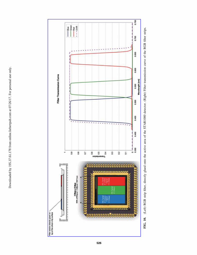
The HRC uses the same monochrome APS as the twoWACs. However, instead of a filter wheel, an affixed red-green-blue filter strip over the CMOS detector is used.1
Covering the spectral range from 440 to 654 nm (atFWHM), the three filter bands (covering, respectively, 342,341, and 341 pixels horizontally) are blue (475 – 35 nm),green (542.5 – 22.5 nm), and red (635 – 19 nm)—seeFig. 10. For color image acquisition, using the three stripefilters on the detector, the camera head has to be pannedover the full FOV to mosaic each color swath across thedetector FOV. We note that optical testing of the HRCelegant breadboard revealed stray light issues relating to thefilter; these have been mitigated by adding a black coatingto the filter edges.
Connected to the focal plane via a flex layer is the controlelectronics PCB, which houses all HRC electronics,
Table 3. WAC Filter Properties for the Left Filter Wheel (Top Half)
and the Right Filter Wheel (Bottom Half)
Filter wheelposition #
Center wavelength(nm)
FWHM band pass(nm)
Average center wavelengthtransmission % Filter ID
L01 570 12 98.9% G04L02 530 15 95.7% G03L03 610 10 95.6% G05L04 500 20 96.6% G02L05 670 12 96.2% G06L06 440 25 98.7% G01L07 640 100 99.3% C01LL08 540 80 98.8% C02LL09 440 120 98.3% C03LL10 925 5 0.0000552% S01L11 935 5 0.0000854% S02
R01 840 25 98.9% G09R02 780 20 98.1% G08R03 740 15 98.3% G07R04 900 30 98.3% G10R05 950 50 99.4% G11R06 1000 50 99.6% G12R07 640 100 99.3% C01RR08 540 80 98.8% C02RR09 440 120 98.3% C03RR10 450 5 0.0001356% S03R11 670 5 0.0000922% S04
Filter ID codes are as follows: G01–G12 = geology filters (10–50 nm bandwidth); C01L–C03L and C01R–C03R = red, green, and bluecolor imaging filters (left and right wheel, respectively, 80–120 nm bandwidth); and S01–S04 = solar filters (5 nm bandwidth).
1The detector for the flight HRC will be changed to a colorBayer detector and the filter strip removed, subject to successfulqualification.
524 COATES ET AL.D
ownl
oade
d by
195
.37.
61.1
78 f
rom
onl
ine.
liebe
rtpu
b.co
m a
t 07/
26/1
7. F
or p
erso
nal u
se o
nly.

including camera control, autofocus and autofocus motorcontrol, and interface control.
To satisfy the stringent alignment requirements, the focalplane is placed on an isostatically mounted bracket. Shimsbetween the focal plane bracket and the OB, as well as
shims between the folding mirror bracket and OB, can beused to further adjust height and angular alignment duringintegration.
The autofocus algorithm is newly developed by the HRCteam. An adapted global search strategy is used to search for
FIG. 8. HRC CAD drawing, and Elegant Breadboard, showing HRC’s components integrated into the PanCam OB.
FIG. 9. HRC block diagram showing the STAR1000 CMOS sensor with temperature sensor, the FPGA (center), con-nectors, power conditioning, and LVDS drivers (right) and finally the focus motor control circuitry (left).
PANCAM FOR THE EXOMARS ROVER 525D
ownl
oade
d by
195
.37.
61.1
78 f
rom
onl
ine.
liebe
rtpu
b.co
m a
t 07/
26/1
7. F
or p
erso
nal u
se o
nly.
FIG
.10.
(Lef
t)R
GB
stri
pfi
lter
,dir
ectl
yglu
edonto
the
acti
ve
area
of
the
ST
AR
1000
det
ecto
r.(R
ight)
Fil
ter
tran
smis
sion
curv
eof
the
RG
Bfi
lter
stri
ps.
526
Dow
nloa
ded
by 1
95.3
7.61
.178
fro
m o
nlin
e.lie
bert
pub.
com
at 0
7/26
/17.
For
per
sona
l use
onl
y.

the sharpest image within the focus range. The sharpness ofan image is determined within a 32 · 32, 64 · 64, 128 · 128,or 256 · 256 window by Sobel filtering and calculation ofthe mean of the root-squared image gradients in x and ydirection. The sharpness at the initial motor position iscalculated by moving the motor either forward or backwarddepending on the current focus position, with a step lengthof 3 mm. Again, the image sharpness is calculated, and themotor movement direction is changed if the sharpness islower than the initial sharpness. Then, steps of 1 mm areexecuted, and the image sharpness is calculated iterativelyuntil a coarse global maximum sharpness is found. At thefinal stage, the step size is reduced to find the global max-imum image sharpness. Although range estimation is notrequired for the HRC autofocus, the drive stage can be setby command at a position calculated based on range-to-target information from the WAC stereo products.
3.4. Optical bench (OB)
PanCam’s internal components are contained in an OB.An OB was selected to provide the instrument with pro-tection from the martian environment (e.g., dust) and toprovide the martian environment protection from any con-taminants brought from Earth by the instrument. The OB isvented with a HEPA filter to equalize pressure but maintaincleanliness. In addition, the rigidity of the OB helps main-tain a stable structure from which to acquire stereo imaging.
The OB is of aluminum construction with dimensions of562 · 70 · 113 mm (L · H · D). The walls are machined from asingle aluminum block, and afterward the interior is cut out byusing electrical discharge machining wire cutting. Wire cuttingallows the OB to have thinner walls than could be machinedfrom a solid block, resulting in a lightweight rigid structure.
The base is electron-beam welded to the wall structure,and the lid is secured to the top of the bench by a series offasteners once the internal components are mounted. In thisconfiguration, the box makes a very stiff, extremely lightmonocoque structure. The mass of the OB itself, including12% margin, is just under 780 g.
The interior of the OB is painted with a black paint(Z306) to cut down on stray light. Aeroglaze Z-306 has areflectance of *8% BoL in the visible (Gilmore, 2002) anda few percent in the NIR (Ames, 1990). The exterior of theOB is coated with A276, a space-qualified white paint thataids PanCam thermal control. Equally importantly, A276 iscompatible with ExoMars planetary protection guidelines; itis glossy and smooth, so it is less likely to harbor spores andother bioburden. It can also withstand dry heat microbialreduction sterilization.
3.5. Supporting electronics—PanCam Interface Unit(PIU) + DC-DC converter (DCDC)
The function of the PIU is to provide a single interface for allthree cameras to the rover and this is achieved by using theSpaceWire RMAP interface protocol. The PIU receives theSpaceWire RMAP packets and executes them as required andforwarding the command to the cameras. Due to power con-straints, only a single camera can be powered at any one time.The active camera is selected by the PIU using power switches.
Single alternating WAC operation (e.g., during stereoimage acquisition) is not expected to present problems
maintaining operating temperature. This is because thermalmodeling indicates that the low thermal conductance to theOB means that one camera is unlikely to cool significantlyin the few minutes it is switched off (while the other isacquiring the matching image in the stereo pair). Alternatingcamera use during a sequence of stereo pairs allows heatloss from each camera to be minimized.
The PIU is responsible for control of the filter wheels. ThePIU maintains locally the Rover Elapsed Time (RET) in orderto allow time-stamping of HK packets and image data. Inaddition to time stamps, images can be identified by a uniqueimage ID that is embedded in the image metadata and con-tains parameters such as the sol date and task ID. Owing toPanCam’s position on the end of the mast and again to powerlimitations, the instrument does not have any survival heatersand follows the martian surface temperature.
Therefore, the cameras will generally be operated during theday when surface temperatures are above -40�C (to reducepower required for heating). An exception may be the solarobservations just prior to sunset (sunrise observations likelybeing precluded by power and thermal restrictions). However,since the rover is solar powered, it is similarly limited to day-time operations when the dust opacity is low enough to enable(and any seasonal constraints allow) a suitable operating powermargin to be maintained (Vago, 2012).
Given this, the PIU provides autonomous camera unittemperature control and monitoring with secondary powerfor the heaters. Moreover, the PIU is responsible for thecontrol of the filter wheels. The performance and state ofPanCam is monitored though the Housekeeping packetsgenerated by the PIU. These Housekeeping packets are alsoused by the rover to detect any off-nominal behavior andtake the appropriate actions.
A single DC-DC converter, which is housed in a dedi-cated compartment of the OB, provides the galvanicallyisolated secondary rails as required by the rest of the in-strument. The DC-DC converter converts the 28 V primarypower bus to three different voltages:
� 12 V, used to drive the filter wheels and the HRC focusactuator;
� 6 V, which powers the various digital components(switched to power the cameras as needed);
� 1.5 V, used by the PanCam FPGA.
The DC-DC converter incorporates a number of featuressuch as current limiting designed to safeguard the rest of theinstrument in the event of a component failure or upset.
3.6. Small Items
The PanCam ‘‘Small Items’’ consist of additional passivehardware to aid the surface operations of PanCam and allowin situ calibration. These items include the PCT, the FidMs,and the RIM. The PCT and FidMs are mounted on the roverdeck and the RIM on the left-hand suspension bogie bracketas shown in Fig. 11.
3.6.1. PanCam Calibration Target (PCT). The PCTprovides an in situ calibration target for the radiometric cal-ibration of PanCam on the martian surface. The PCT hasa mass of 36.2 g excluding mounting screws and consists ofan aluminum structure with a surface area of 67 · 76 mm,which mechanically retains eight colored glass and ceramic
PANCAM FOR THE EXOMARS ROVER 527D
ownl
oade
d by
195
.37.
61.1
78 f
rom
onl
ine.
liebe
rtpu
b.co
m a
t 07/
26/1
7. F
or p
erso
nal u
se o
nly.

calibration patches. Six of the calibration patches (red, yel-low, green/blue, blue, and two gray) have an exposed diam-eter of 18 mm and will be used only for PanCam calibration.Colored glass was selected for the calibration patches, as thecolor has excellent resistance to UV-induced fading anddamage from the moderate doses of ionizing radiation it willencounter during the mission. The surfaces of the calibrationpatches are processed to obtain a diffuse reflection, and theback surface is aluminized to increase the total reflectance.The glass for the six small calibration patches is standardSchott colored and neutral-density filter glass.
The white and multiband calibration patches have anexposed diameter of 30 mm and will be used for the radio-metric and spectral calibration of ISEM (Korablev et al.,2017, in this issue) in addition to PanCam. WCT-2065 (arare earth doped glass developed by NIST and manufacturedby Schott) is used to provide well-defined bands for spectralcalibration applications in the visible and NIR. The whitecalibration patch is Pyroceram manufactured by the VavilovState Optical Institute in St. Petersburg.
The calibration patches will be calibrated for absolutereflectance in total hemispherical/8� geometry and BRDFso that the angle of incident solar illumination can becompensated for. The PCT includes two shadow posts toallow the level of indirect (scattered) skylight to be as-sessed and aid in the determination of the illuminationdirection and angle.
The PCT is mounted on the front of the rover deck in aregion as clear as possible from sources of shadowing andstray light and will be viewed by PanCam from an angle of*23� from the vertical. Measurements of the light scatteredby the PCT will allow the level of incident illumination tobe determined over the PanCam and ISEM spectral range. Incombination with preflight calibration data, these measure-ments will allow PanCam images to be processed to obtaincalibrated data products such as spectral parameter imagesand relative reflectance spectra of objects in the FOV.
Dust deposition on the PCT during the ExoMars missionwill be accounted for in the data processing by developing aradiative transfer model of the PCT/dust system, building onthe results of previous missions ( Johnson et al., 2002; Bellet al., 2006; Kinch et al., 2007, 2015). This will use labo-ratory measurements of Mars analog dust ( JSC Mars-1;Allen et al., 1997) on the PCT prototype as with the MERcalibration target ( Johnson et al., 2006) and measurementsof settling rates derived from the rover solar array poweroutput (Stella et al., 2005).
3.6.2. Fiducial Markers (FidMs). Together with the PCT,the three FidMs form two right-angle triangles on the roverdeck to allow in situ geometric calibration of the PTU/PanCam system. Each FidM consists of a single piece ofaluminum, anodized black and with the center sectionground back to aluminum to provide high contrast. The
FIG. 11. PanCam Small Items and their locations on the rover.
528 COATES ET AL.D
ownl
oade
d by
195
.37.
61.1
78 f
rom
onl
ine.
liebe
rtpu
b.co
m a
t 07/
26/1
7. F
or p
erso
nal u
se o
nly.

center hole in each FidM provides a mounting point forgeometric reference targets for preflight calibration activi-ties. The FidMs have dimensions of 32 · 16 · 6.5 mm and amass of 1.2 g excluding mounting screws.
3.6.3. Rover Inspection Mirror (RIM). The RIM is a50 mm diameter convex spherical mirror machined andpolished from aluminum, with a radius of curvature of30 mm mounted on an aluminum bracket. The RIM as-sembly has a mass of 21.8 g excluding mounting screws.The RIM will be imaged by the HRC and will allow the drillspoil heap to be observed while drilling is taking place. Itwill also allow the underside of the rover to be observed fordiagnosis in the event of problems with uneven surfaces, thedrivetrain, and so on. The RIM will also allow the PanCaminstrument to take ‘‘selfies’’ of the rover for publicity andoutreach purposes.
4. Measurement Scenario
4.1. Usage of PanCam
The ExoMars mission plan is to explore the martian ter-rain near the landing site using a series of six experimentcycles and two vertical surveys (Vago et al., 2015, 2017).The rover will target outcrops as indicators of buried rockmasses that may extend below the radiation-altered andoxidized layers to depths of >1.5 m where molecular fossilsmay have survived for billions of years.
A ‘‘reference surface mission,’’ involving experimentcycles, has been designed to provide the necessary re-quirements for sizing the rover. The discussion in this sec-tion is based on that existing plan, which also provides arough template for achieving the main scientific goals dur-ing the nominal surface mission. We fully appreciate thatthe detailed planning for Mars operations will vary signifi-cantly from this scenario. Inputs from the science and en-gineering teams for PanCam and other instruments will begenerated on a daily basis as the mission progresses, in re-action to the martian terrain and environment and to thestate of the rover.
In an experiment cycle (EC), the rover uses the Pasteurpayload (over a period of 14 sols, with another 4 sols re-served for traveling between EC sites) to home in on asuitable outcrop from which to acquire samples (Vago,2012). For particularly promising EC sites, a vertical surveycan be conducted where samples are returned every 50 cmfrom the surface to the maximum drilling depth of 2 m.
The EC can be divided into an approach phase (3–4 sols)and a sampling phase (10–11 sols). At the beginning of theapproach phase, the rover can be up to 20 m distant from apossible drill target, so a PanCam WAC panorama of up to10 RRGB color/stereo images of the area ahead of the roveris acquired on the first sol. At the same time, HRC RGBcolor images and co-registered ISEM spectra (Korablevet al., 2017, in this issue) of promising rocks (seen duringthe *100 m drive from the previous EC location) are ac-quired. From these data, an outcrop target will be chosen forthe rover to approach to *3 m on the second sol. ADRON(Mitrofanov et al., 2017, in this issue) and WISDOM(Ciarletti et al., 2017, in this issue) surveys are conductedduring the approach phase. A WAC image using either all12 geology filters or selected groups (as discussed in Section
3.1) is taken of the outcrop along with a mosaic of eightHRC color images (and again eight co-registered ISEMspectra). Then on the third sol, a HRC color context image istaken of the potential drill target area to be imaged in greaterdetail by CLUPI. Subsequently, CLUPI will acquire up tosix images (with depth from focus position information) tocharacterize rock microtexture and select a location to drill.Finally, on the forth sol of the approach phase, a surfacesample is acquired and imaged by the HRC and CLUPIbefore ingestion into the ALD by the HRC and CLUPI. Inthis way, PanCam forms part of the ‘‘remote sensing’’ partof the Pasteur payload (along with WISDOM, ADRON,ISEM, and CLUPI) used to determine where to drill andacquire a sample.
During the EC sampling phase, the ‘‘remote sensing’’ in-struments are used less frequently, with the ALD instrumentstaking center stage. However, assuming the surface sampleresults are promising, on the sixth sol a 6-position WACRRGB mosaic is acquired to help plan a WISDOM patternsearch for a location to drill deeper for unaltered samples. TheWAC is used again on the seventh sol to acquire 12 RRGBimages to increase the accuracy of the knowledge of roverpositioning at the corners of the WISDOM pattern.
Next, on the eighth sol while drilling to at least 1.5 mdepth is proceeding, the WAC is used to acquire a further 10RRGB images for strategic planning (e.g., to help determinethe drive direction for the following EC). The final use ofPanCam during the sampling phase is on the 10th sol toimage the retrieved subsurface sample with the HRC (alongwith CLUPI) before ingestion into the ALD.
Between the 11th and 13th sols, PanCam rests while theALD instruments analyze the subsurface sample. Then,from the 14th to 18th sol, the rover drives to the next EClocation, while conducting WISDOM and ADRON sound-ings. The only PanCam activity on these sols is the possibleacquisition of WAC broadband red filter stereo pairs (ormosaics of stereo pairs) to provide higher-resolution views(than available with the NavCams) to help plan the rovers’course to the next EC location.
During the mission’s two vertical surveys, the PanCam ismostly inactive while the rover drills at a single location.HRC images of the samples prior to ingestion can again beenvisaged.
4.2. Instrument performance examples
The instrument performance will be determined from theintegrated PanCam instrument and from calibration whenthe instrument has been assembled (see Section 5.1–5.2). Atpresent, representative examples have been produced byusing PanCam emulators such as the AUPE-2 AberystwythUniversity PanCam Emulator 2 (e.g., Pugh et al., 2012;Harris et al., 2015) and breadboard models, but the actualinstrument performance examples are not available as yet.
A number of ExoMars-related field trials and tests havebeen performed in the last few years (see Fig. 12), includingparticipation in recent Arctic Mars Analogue Svalbard Ex-peditions (AMASE) 2008–2015 (see Schmitz et al., 2009;Steele et al., 2010), the SAFER campaign in the AtacamaDesert in 2013 (Gunes-Lasnet et al., 2014), and field trials inIceland in 2013 (Harris et al., 2015). For these tests, a rep-resentative PanCam simulator was used, which was provided
PANCAM FOR THE EXOMARS ROVER 529D
ownl
oade
d by
195
.37.
61.1
78 f
rom
onl
ine.
liebe
rtpu
b.co
m a
t 07/
26/1
7. F
or p
erso
nal u
se o
nly.

by Aberystwyth University. This simulator includes repre-sentative (though not the final) filter wavelengths from whichspectral information may be used to study mineralogy. Thesecampaigns have been used, in combination with teams fromother ExoMars instruments, to develop working proceduresrepresentative of a mission to Mars, as well as to test instru-ment performance, develop calibration techniques, and pursuescientific investigations of particular areas. These included, forexample, the Bockfjord Volcanic Complex and the Nordaus-tlandet/Palander Icecap. Scientific data from these trials arediscussed elsewhere (Schmitz et al., unpublished data).
Other PanCam ground tests have included ‘‘blind’’ geo-logical identifications performed in the AU Mars analogfacility, tests in a quarry in Hertfordshire with the AstriumUK ‘‘Bridget’’ prototype rover, a field trial in Shropshire in2015, and deployment in Boulby mine (Payler et al., 2017).
5. Calibration and 3-D Vision
5.1. Radiometric calibration plan
Raw PanCam images will be processed to remove imageartifacts caused by the camera system and convert digitalnumbers into calibrated radiometric values. These processingactivities will be implemented in the PanCam data processingpipeline at the ROCC. To correct camera-induced imageartifacts and obtain a true representation of the scene viewedby PanCam, radiometric calibration measurements to fullycharacterize the camera properties will be necessary.
The radiometric calibration of the PanCam instrumentwill comprise a combination of component- and system-level measurements to characterize the properties of variousparts of the instrument. Component-level calibrations willmeasure camera properties including the following: detectordark current and bias, detector linearity, detector hot/coldpixels, filter absolute transmission, PCT reflectance, and soon. System level calibrations will characterize properties ofthe complete system and include the following: flat-fieldmeasurements to determine the non-uniformity in the re-
sponse of the optical system, measurements of system ra-diometric response, measurements of system spectralresponse and the response of the system to stray light. Darkcurrent and flat fields will also be acquired periodically inflight to determine the effects of thermal cycling and radi-ation exposure on the detector response.
Many of the camera properties will be temperature-dependent, so calibration will be carried out as a function oftemperature. The PanCam instrument together with calibrationhardware, including an integrating sphere, will be mounted in athermal vacuum chamber (TVC) at MSSL (see Fig. 13b) sothat measurements can be carried out over the full operatingtemperature range of the system: -50�C to 35�C. Thesemeasurements will be interpolated to the sensor temperaturerecorded for the in-flight images to allow the modeled sensorresponse to be subtracted and estimates of remaining errors tobe derived (following the methods of Bell et al., 2006).
The integrating sphere will be mounted on a lineartranslation stage so that it can be placed in front of each ofthe PanCam cameras without breaking vacuum. Lightsources for the integrating sphere will include white light forflat-field and linearity measurements and a tunable lightsource incorporating a monochromator for spectral calibra-tions. The light sources and a calibrated monitor spec-trometer will be located outside the TVC and coupled viaoptical fibers. PanCam calibration measurements will betraceable to national standards laboratories (NIST) via ap-propriate calibration standards. These will include a cali-brated light source to achieve absolute radiometric calibrationand reflectance standards to determine the absolute reflec-tance of the PCT.
5.2. Geometric calibration plan
The geometric calibration of the PanCam involves all thesteps required to define its components in a common coor-dinate system. This coordinate system will allow local re-construction of the information collected by the PanCamcomponents at each rover position on Mars.
FIG. 12. Views of AUPE PanCam simulator at tests in a Hertfordshire, UK, quarry (bottom left) and at the AMASEcampaign, Svalbard.
530 COATES ET AL.D
ownl
oade
d by
195
.37.
61.1
78 f
rom
onl
ine.
liebe
rtpu
b.co
m a
t 07/
26/1
7. F
or p
erso
nal u
se o
nly.

To perform calibration, first each PanCam camera mustbe calibrated individually, second relative to each other, andthen to the rest of the PanCam components. This last step iscalled cross-calibration.
The individual calibration of the WACs and HRC willcompute the coordinates of the principal point, the focallength, and the lens distortion coefficients for each camerathat is called intrinsic orientation (IO)—various represen-tations are available. PanCam will use a derivative of theTSAI model (Tsai, 1987) with the option to convert to otherwell-known schemes such as CAHVOR (Di and Li, 2004).The IO of the WACs will be obtained by using one repre-sentative filter (e.g., the red RGB component); distortion ofother filters is measured in comparison to it by measuringthe relative distortion. For HRC IO, the calibration usingtwo different focal lengths is needed. The cross-calibrationdetermines the geometric relationship between all PanCamcomponents, which are mathematically expressed as 3-D-Helmert transformations, as displayed in Fig. 13a.
Changes in the IOs of the WACs and HRC will be ob-served by executing several temperature transitions in vac-uum. Further exhaustive tests will be conducted in ambientconditions outside the TVC to assess the dependency of thefilter wavelengths on the WAC IOs and the stability of theWAC and HRC IO and relative orientation after rotating thecameras around the Pan and Tilt Unit (PTU).
The original plan to bring a full setup of 3-D target points,measured by an optical coordinate metrology system (e.g.,Vicon), into the calibration clean room was abandoned dueto planetary protection and laboratory space reasons. In-stead, a flat calibration target that fulfils the planetary pro-tection requirements, that is, appropriate for dry heatmicrobial reduction, will be used. It consists of an aluminumtarget containing a set of randomly distributed points indifferent scales to fit the WAC and HRC needs simulta-neously, as displayed in Fig. 13c. Furthermore, in contrast toup-to-date approaches of targets with regular patterns (Bellet al., 2003; Edgett et al., 2015), the target can cover the fullimage, and the points can still be automatically detected andcorrectly assigned to perform a fully automatic calibrationusing hundreds of images.
The final AIT task requires measurements of the relativecalibration between the rover and OB, PTU, FidMs, and Mast.The current plan is to accomplish this by cross-calibration withNavCam and additional adjustment of the WACs versus thePTU axes by multiple overlapping image observations undervarying PTU angles and overlapping observations of the roverdeck and fiducial markers under varying PTU angles.
Cross-calibration with ISEM and CLUPI will be obtainedby multiple simultaneous viewing of the same target (e.g.,the PCT), followed by an adjustment procedure. Cross-calibration to WISDOM will be done only indirectly based
FIG. 13. (a) PanCam embedded in the Geometric transformations chain of the ExoMars rover. The main element is therover frame with various elements attached such as Drill or WISDOM (bottom). The cascade relevant for PanCam is thetransform between rover and PTU, followed by the transform between PTU and WACL—depending on the pan-tilt values.WACL, HRC, and WACR are described in the PanCam coordinate system. In addition, for fusion purposes PanCam(WACL) will be cross-calibrated with NavCam and ISEM. (b) MSSL TVC to be used for WACs/HRC calibration in openstate. (c) PanCam geometric calibration target design with random dot pattern for WACs (large dots) and HRC (small dots).
PANCAM FOR THE EXOMARS ROVER 531D
ownl
oade
d by
195
.37.
61.1
78 f
rom
onl
ine.
liebe
rtpu
b.co
m a
t 07/
26/1
7. F
or p
erso
nal u
se o
nly.

on the PanCam and WISDOM individual alignment in therover coordinate system.
Verification and possible correction of the calibration onMars will be obtained by bundle adjustment of single stereopairs and overlapping patches of stereo panoramas.
5.3. 3-D vision
Three-dimensional scene reconstruction from PanCamstereo imagery is established by the processing frameworkPRoViP (Planetary Robotics Vision Processing). Startingwith images from the instrument available via the ESAPlanetary Science Archive or NASA Planetary Data System(during the mission the data will be directly from downlinksources in the ROCC), stereo matching is performed, fol-lowed by 3-D reconstruction into DTMs in various geome-tries, generation of an intermediate data set (‘‘GPC’’: GenericPoint Cloud), combination of the DTMs into unique consis-tent mosaicked products, and finally the export into productsto be exploited by scientists and operations personnel.
Examples of processing products and capabilities are asfollows:
(a) Digital Elevation Models in spherical, cylindrical, andCartesian coordinate space;
(b) Ortho images;(c) 3-D meshes;(d) Derived thematic maps of the surroundings, describ-
ing reconstruction accuracy, occlusions, solar illumi-nation, slopes, roughness, hazards, and so on;
(e) Fusion of rover- and orbiter-based images;(f) Fusion between WAC and HRC 3-D vision data
products (e.g., overlay of WAC DTM/ortho imageswith HRC texture).
PRoViP has been extensively tested with various Marsmission data sets from sensors similar to PanCam, includingMSL Mastcam (Barnes et al., 2015a, Paar et al., 2016a, 2016b)(see Fig. 14).
For immersive 3-D presentation of the PanCam 3-D vi-sion products, we will use an interactive 3-D viewing toolcalled ‘‘PRo3D’’ (Planetary Robotics 3D Viewer, Barneset al., 2015b), which allows one to virtually explore re-constructed martian terrain and perform geological analysis
(Fig. 15). PRo3D builds upon the ideas of existing renderingtools used for tactical and strategic planning such as com-bining the rover CAD model with the 3-D reconstructedenvironment (Poulakis et al., 2008; Cooper et al., 2013;Proton, 2015) or the exploitation of image poses to generatevirtual views (Howard, 2015). In addition, it goes beyondthe approach of transition between panoramas and 3-D en-vironment followed in Google Mars but gives simultaneousreal-time access to different resolutions from planetary tomicroscopic level and therefore allows an interactive fusionof rover image products and orbiter DTMs (Paar et al.,2015), closing the loop between 3-D vision processing andimmersive 3-D geology. Various measurement and annota-tion tools are provided to
(a) Delineate geological boundaries,(b) Obtain the true dimension of geological features,(c) Obtain linear and projected distances between surface
points,(d) Calculate dip and strike values of stratigraphic layers.
6. Conclusions
We have described the scientific objectives of PanCam, itsdesign, and how it will be used, as well as calibration methodsand 3-D vision capabilities. PanCam has several powerful no-vel capabilities in terms of Mars camera deployment:
� The WAC spacing, 50 cm, gives excellent stereo re-construction
� The WAC-HRC combination allows rock texture to besuperimposed on the excellent DTMs
� The WAC filters have been specifically designed toreduce uncertainty in the identification of water-richminerals
� WAC will perform atmospheric science measurements,that is, water vapor and dust determination, cloudmonitoring
� The HRC will provide rock texture information andwill be able to view drill tailings, samples, and under-neath the rover
� PanCam will perform synergistic work with othercontext instruments (ISEM CLUPI, WISDOM,ADRON, and Ma_MISS)
FIG. 14. (Left) Result of MSL Mastcam processing of Garden City outcrop area taken at MSL Sol 926 and 929 (DTM,rendered by PRo3D) making use of ExoMars PanCam 3-D vision processing workflow scheme PRoViP. (Right) 3-D renderedMSL Mastcam stereo processing results at subcentimeter resolution, as appearing in PRo3D Graphical User Interface.
532 COATES ET AL.D
ownl
oade
d by
195
.37.
61.1
78 f
rom
onl
ine.
liebe
rtpu
b.co
m a
t 07/
26/1
7. F
or p
erso
nal u
se o
nly.

In summary, PanCam will be a highly capable scientificcamera system for the martian surface with an excellentanticipated scientific performance for geology, using filtersselected for accurate identification of water-rich mineralsand for atmospheric science and exobiology.
Acknowledgments
We thank the ExoMars project team and Industry for theirhard work on the ExoMars rover. We acknowledge supportfrom the UK Space Agency (lead funding agency for Pan-Cam) and STFC, DLR agency, Swiss Space Office (viaPRODEX), Austrian agency. We thank the PanCam scienceteam for help over the years. PanCam would not be possiblewithout vital engineering support at MSSL (T. Hunt, J.Jones, C. Theobald, B. Winter, B. Hancock, G. Davison, A.Spencer, A. Rousseau, V. Botelho, P. Yuen, P. Janicki),DLR, OHB, RUAG and Joanneum Research/VRVIS.
References
Allen, C.C., Morris, R.V., Lindstrom, D.J., Lindstrom, M.M.,and Lockwood, J.P. (1997) JSC Mars-1: martian regolith si-mulant [abstract 1797]. In 28th Lunar and Planetary ScienceConference, Lunar and Planetary Institute, Houston.
Ames, A.J. (1990) Z306 black paint measurements. Proc SPIE1331:299–304.
Anderson, R., Bridges, J.C., Williams, A., Edgar, L., Ollila, A.,Williams, J., Nachon, M., Mangold, N., Fisk, M., Schieber, J.,Gupta, S., Dromart, G., Wiens, R., Le Mouelic, S., Forni, O.,Lanza, N., Mezzacappa, A., Sautter, V., Blaney, D., Clark, B.,Clegg, S., Gasnault, O., Lasue, J., Leveille, R., Lewin, E.,Lewis, K.W., Maurice, S., Newsom, H., Schwenzer, S.P., andVaniman, D. (2015) ChemCam results from the Shaler out-crop in Gale Crater, Mars. Icarus 249:2–21.
Anderson, R.B. and Bell, J.F. (2013) Correlating multispectralimaging and compositional data from the Mars ExplorationRovers and implications for Mars Science Laboratory. Icarus223:157–180.
Arvidson, R.E. (2015) Roving on Mars with Opportunity andCuriosity: terramechanics and terrain properties. In Earthand Space 2014: Engineering for Extreme Environments,Proceedings of the 14th Biennial ASCE Conference on En-gineering, Science, Construction, and Operations in Chal-lenging Environments, edited by L.S. Gertsch and R.B.Malla, American Society of Civil Engineers, Reston, VA, pp165–173.
Arvidson, R.E., Anderson, R.C., Bartlett, P., Bell, J.F., Chris-tensen, P.R., Chu, P., Davis, K., Ehlmann, B.L., Golombek,M.P., Gorevan, S., Guinness, E.A., Haldemann, A.F.C.,Herkenhoff, K.E., Landis, G., Li, R., Lindemann, R., Ming,D.W., Myrick, T., Parker, T., Richter, L., Seelos, F.P., So-derblom, L.A., Squyres, S.W., Sullivan, R.J., and Wilson, J.(2004) Localization and physical property experiments con-
FIG. 15. Screenshot of PRo3D showing a geological interpretation session in the Shaler area (Gale Crater, MSL mission),based on PRoViP 3-D reconstruction from a set of 99 MSL Mastcam stereo images. This detailed interpretation of thestratigraphy shows the main stratigraphic boundaries as gray lines, bedset boundaries as thick white lines, and laminationswithin those bedsets as thin white lines (note that the original image is in color). The dip and strike values are availabledirectly in PRo3D in color coded by dip value and generally dip 15–20� to the southeast (validation forthcoming). Thefindings are consistent with those in the works of Anderson et al. (2015) and Edgar et al. (2014) in that the outcroprepresents a changing fluvial environment, with recessive, fine-grained units interlayered with coarse, pebbly units. Datacourtesy of NASA/JPL, image courtesy of Imperial College London, Robert Barnes/Sanjeev Gupta; www.provide-space.eu
PANCAM FOR THE EXOMARS ROVER 533D
ownl
oade
d by
195
.37.
61.1
78 f
rom
onl
ine.
liebe
rtpu
b.co
m a
t 07/
26/1
7. F
or p
erso
nal u
se o
nly.

ducted by Opportunity at Meridiani Planum. Science306:1730–1733.
Arvidson, R.E., Bell, J.F., Catalano, J.G., Clark, B.C., Fox,V.K., Gellert, R., Grotzinger, J.P., Guinness, E.A., Her-kenhoff, K.E., Knoll, A.H., Lapotre, M.G.A., McLennan,S.M., Ming, D.W., Morris, R.V., Murchie, S.L., Powell, K.E.,Smith, M.D., Squyres, S.W., Wolff, M.J., and Wray, J.J.(2015) Mars Reconnaissance Orbiter and Opportunity ob-servations of the Burns Formation: crater hopping at Mer-idiani Planum. J Geophys Res: Planets 120:429–451.
Arvidson, R.E., Iagnemma, K.D., Maimone, M., Fraeman, A.A.,Zhou, F., Heverly, M.C., Bellutta, P., Rubin, D., Stein, N.T.,Grotzinger, J.P., and Vasavada, A.R. (2017) Mars ScienceLaboratory Curiosity rover megaripple crossings up to Sol 710in Gale Crater. Journal of Field Robotics 34:495–518.
Balme, M., Fawdon, P., Grindrod, P., Gupta, S., Michalski, J.,Carter, J., Muller, J.-P., and Sidiropoulos, P. (2014) Inverted,exhumed channel system in Oxia Palus. In First ExoMarsLanding Site Selection Workshop, 26–28 March 2014, ESAC,Villanueva de la Canada, Madrid, Spain.
Balme, M., Grindrod, P., Davis, J., Fawdon, P., Sefton-Nash, E.,Gupta, S., Butcher, F., Carter, J., Muller, J.-P., Sidiropoulos,P., and Yershov, V. (2015) Aram Dorsum. In Third ExoMarsLanding Site Selection Workshop, 20–21 October 2015, ES-TEC, Noordwijk, the Netherlands.
Barnes, R., Paar, G., Traxler, C., Muller, J.-P., Tao, Y., Sander,K., Gupta, S., Ortner, T. and Fritz, L. (2015a) PRo3D: in-teractive geologic assessment of planetary 3D vision dataproducts. In International Congress on Stratigraphy (STRATI2015). Available online at http://www.vrvis.at/publications/pdfs/PB-VRVis-2015-028.pdf
Barnes, R., Ortner, T., Huber, B., Paar, G., Muller, J.-P.,Giordano, M., and Willner, K. (2015b) PRo3D�: a tool forhigh resolution rendering and geological analysis of martianrover-derived digital outcrop models [paper no. 35-17]. InGeological Society of America Abstracts with Programs,47:111. Available online at https://gsa.confex.com/gsa/2015AM/webprogram/Paper265784.html
Beauvivre, S., Lamy, P., Nguyen-Trong, T., and Reynaud, J.L.(1999) The panoramic camera of the ROSETTA mission:performances of prototype 3D microcameras. Adv Space Res24:1105–1114.
Bell, J.F., Squyres, S.W., Herkenhoff, K.E., Maki, J.N., Arne-son, H.M., Brown, D., Collins, S.A., Dingizian, A., Elliot,S.T., Hagerott, E.C., Hayes, A.G., Johnson, M.J., Johnson,J.R., Joseph, J., Kinch, K., Lemmon, M.T., Morris, R.V.,Scherr, L., Schwochert, M., Shepard, M.K., Smith, G.H.,Sohl-Dickstein, J.N., Sullivan, R.J., Sullivan, W.T., andWadsworth, M. (2003) Mars Exploration Rover Athena Pa-noramic Camera (Pancam) investigation. J Geophys Res 108,doi:10.1029/2003JE002070.
Bell, J.F., Joseph, J., Sohl-Dickstein, J.N., Arneson, H.M.,Johnson, M.J., Lemmon, M.T., and Savransky, D. (2006) In-flight calibration and performance of the Mars ExplorationRover Panoramic Camera (Pancam) instruments. J GeophysRes 111, doi:10.1029/2005JE002444.
Bibring, J.-P., Hamm, V., Pilorget, C., Vago, J.L., and theMicrOmega Team. (2017) The MicrOmega investigationonboard ExoMars. Astrobiology 17, 621–626.
Bishop, J.L., Noe Dobrea, E.Z., McKeown, N.K., Parente, M.,Ehlmann, B.L., Michalski, J.R., Milliken, R.E., Poulet, F.,Swayze, G.A., Mustard, J.F., Murchie, S.L., and Bibring, J.P.
(2008) Phyllosilicate diversity and past aqueous activity re-vealed at Mawrth Vallis, Mars. Science 321:830–833.
Bridges, J.C., Schwenzer, S.P., Leveille, R., Westall, F., Wiens,R., Mangold, N., Bristow, T., Edwards, P., and Berger, G.(2015) Diagenesis and clay formation at Gale Crater, Mars.J Geophys Res 120, doi:10.1002/2014JE004757.
Bridges, J.C., Henson, R.A., Vago, J.L., Loizeau, D., Williams,R.M.E., Hauber, E., and Sefton-Nash, E. (2016a) ExoMarslanding site characterisation and selection [abstract 2170]. In47th Lunar and Planetary Science Conference, Lunar andPlanetary Institute, Houston.
Bridges, J.C., Edwards, P.H., Anderson, R., Dyar, M.D., Fisk,M., Thompson, L., Gasda, P., Schwenzer, S.P., Goetz, W.,Blaney, D., Filiberto, J., and Wiens, R.C. (2016b) Igneousdifferentiation on Mars: trachybasalts in Gale Crater [abstract2160]. In 47th Lunar and Planetary Science Conference,Lunar and Planetary Institute, Houston.
Bridges, N.T., Calef, F.J., Hallet, B., Herkenhoff, K.E., Lanza,N.L., Le Mouelic, S., Newman, C.E., Blaney, D.L., Pablo,M.A., Kocurek, G.A., Langevin, Y., Lewis, K.W., Mangold,N., Maurice, S., Meslin, P.-Y., Pinet, P., Renno, N.O., Rice,M.S., Richardson, M.E., Sautter, V., Sletten, R.S., Wiens, R.C.,and Yingst, R.A. (2014) The rock abrasion record at GaleCrater: Mars Science Laboratory results from BradburyLanding to Rocknest. J Geophys Res: Planets 119:1374–1389.
Cady, S.L., Farmer, J.D., Grotzinger, J.P., Schopf, J.W., andSteele, A. (2003) Morphological biosignatures and the searchfor life on Mars. Astrobiology 3:351–368.
Christensen, P.R., Wyatt, M.B., Glotch, T.D., Rogers, A.D.,Anwar, S., Arvidson, R.E., Bandfield, J.L., Blaney, D.L.,Budney, C., Calvin, W.M., Fallacaro, A., Fergason, R.L.,Gorelick, N., Graff, T.G., Hamilton, V.E., Hayes, A.G.,Johnson, J.R., Knudson, A.T., McSween, H.Y., Jr., Mehall,G.L., Mehall, L.K., Moersch, J.E., Morris, R.V., Smith, M.D.,Squyres, S.W., Ruff, S.W., and Wolff, M.J. (2004) Miner-alogy at Meridiani Planum from the Mini-TES experiment onthe Opportunity Rover. Science 306:1733–1739.
Ciarletti, V., Clifford, S., Plettemeier, D., Le Gall, A., Herve, Y.,Dorizon, S., Quantin-Nataf, C., Benedix, W.-F., Schwenzer,S., Pettinelli, E., Heggy, E., Herique, A., Berthelier, J.-J.,Kofman, W., Vago, J.L., Hamran, S.-E., and the WISDOMTeam. (2017) The WISDOM radar: unveiling the subsurfacebeneath the ExoMars Rover and identifying the best locationsfor drilling. Astrobiology 17, 565–584.
Cooper, B.K., Maxwell, S.A., Hartman, F.R., Wright, J.R., Yen,J., Toole, N.T., Gorjian, Z., and Morrison, J.C. (2013, Sep-tember) Robot sequencing and visualization program (RSVP).NASA Tech Briefs. Available online at http://ntrs.NASA.gov/search.jsp?R=20140001459
Cos, S., Uwaerts, D., Bogaerts, J., and Ogiers, W. (2006) ActivePixels for Star Trackers: Final Report, Doc. Nr: APS-FF-SC-05-023, Dated 24-03-2006, Issue: 1, Cypress SemiconductorCorp. BVBA, Mechelen, Belgium.
Cousins, C.R., Griffiths, A.D., Crawford, I.A., Prosser, B.J.,Storrie-Lombardi, M.C., Davis, L.E., Gunn, M., Coates, A.J.,Jones, A.P., and Ward, J.M. (2010) Astrobiological consid-erations for the selection of the geological filters on theExoMars PanCam instrument. Astrobiology 10:933–951.
Cousins, C.R., Gunn, M., Prosser, B.J., Barnes, D.P., Crawford,I.A., Griffiths, A.D., Davis, L.E., and Coates, A.J. (2012)Selecting the geology filter wavelengths for the ExoMarsPanoramic Camera instrument. Planet Space Sci 71:80–100.
534 COATES ET AL.D
ownl
oade
d by
195
.37.
61.1
78 f
rom
onl
ine.
liebe
rtpu
b.co
m a
t 07/
26/1
7. F
or p
erso
nal u
se o
nly.

Craddock, R.A. and Golombek, M.P. (2016) Characteristics ofterrestrial basaltic rock populations: implications for Marslander and rover science and safety. Icarus 274:50–72.
Davies, N.S., Liu, A.G., Gibling, M.R., and Miller, R.F. (2016)Resolving MISS conceptions and misconceptions: a geolog-ical approach to sedimentary surface textures generated bymicrobial and abiotic processes. Earth-Science Reviews154:210–246.
De Kok, R., Irwin, P.G.J., Tsang, C.C.C., Piccioni, G., andDrossart, P. (2011) Scattering particles in nightside limbobservations of Venus’ upper atmosphere by Venus ExpressVIRTIS. Icarus 211:51–57.
De Sanctis, M.C., Altieri, F., Ammannito, E., Biondi, D., DeAngelis, S., Meini, M., Mondello, G., Novi, S., Paolinetti, R.,Soldani, M., Mugnuolo, R., Pirrotta, S., Vago, J.L., and theMa_MISS team. (2017) Ma_MISS on ExoMars: mineralog-ical characterization of the martian subsurface. Astrobiology17:612–620.
Di, K. and Li, R. (2004) CAHVOR camera model and itsphotogrammetric conversion for planetary applications. JGeophys Res: Planets 109, doi:10.1029/2003JE002199.
Di Achille, G. and Hynek, B.M. (2010) Ancient ocean on Marssupported by global distribution of deltas and valleys. NatGeosci 3:459–463.
Edgar, L.A., Grotzinger, J.P., Hayes, A.G., Rubin, D.M.,Squyres, S.W., Bell, J.F., and Herkenhoff, K.E. (2012) Stra-tigraphic architecture of bedrock reference section, VictoriaCrater, Meridiani Planum, Mars. In Sedimentary Geology ofMars, SEPM Special Publication No. 102, edited by J.Grotzinger and R. Milliken, Society for Sedimentary Geol-ogy, Tulsa, OK, pp 195–209.
Edgar, L.A., Gupta, S., Rubin, D.M., Lewis, K.W., Kocurek,G.A., Anderson, R.B., Bell, J.F., Dromart, G., Edgett, K.S.,Grotzinger, J.P., Hardgrove, C., Kah, L.C., Leveille, R.,Malin, M.C., Mangold, N., Milliken, R.E., Minitti, M., Pa-lucis, M., Rice, M., Rowland, S.K., Schieber, J., Stack, K.M.,Sumner, D.Y., Williams, A.J., Williams, J., and Williams,R.M.E. (2014) A fluvial sandbody on Mars: reconstruction ofthe Shaler outcrop, Gale Crater, Mars [abstract 1648]. In 45th
Lunar and Planetary Science Conference, Lunar and Plane-tary Institute, Houston.
Edgett, K.S., Yingst, R.A., Ravine, M.A., Caplinger, M.A.,Maki, J.N., Ghaemi, F.T., Schaffner, J.A., Bell, J.F., III,Edwards, L.J., Herkenhoff, K.E., Heydari, E., Kah, L.C.,Lemmon, M.T., Minitti, M.E., and Olsonshow, T.S. (2012)Curiosity’s Mars Hand Lens Imager (MAHLI) investigation.Space Sci Rev 170:259–317.
Edgett, K.S., Caplinger, M.A., Maki, J.N., Ravine, M.A.,Ghaemi, F.T., McNair, S., Herkenhoff, K.E., Duston,B.M., Willson, R.G., Yingst, R.A., Kennedy, M.R., Mini-tti, M.E., Sengstacken, A.J., Supulver, K.D., Lipkaman,L.J., Krezoski, G.M., McBride, M.J., Jones, T.L., Nixon,B.E., Van Beek, J.K., Krysak, D.J., and Kirk R.L. (2015)Curiosity’s Robotic Arm-Mounted Mars Hand Lens Imager(MAHLI): Characterization and Calibration Status, MSLMAHLI Technical Report 0001 (version 1: 19 June 2015; ver-sion 2: 05 October 2015), doi:10.13140/RG.2.1.3798.5447.
Ehlmann, B.L., Mustard, J.F., Fassett, C.I., Schon, S.C., Head,J.W., Des Marais, D.J., Grant, J.A.,and Murchie, S.L. (2008)Clay minerals in delta deposits and organic preservation po-tential on Mars. Nat Geosci 1:355–358.
Farmer, J.D. and Des Marais, D.J. (1999) Exploring for a recordof ancient martian life. J Geophys Res 104:26977–26995.
Farrand, W.H., Bell, J.F., Johnson, J.R., Squyres, S.W., So-derblom, J., and Ming, D.W. (2006) Spectral variabilityamong rocks in visible and near-infrared multispectral Pan-cam data collected at Gusev Crater: examinations usingspectral mixture analysis and related techniques. J GeophysRes 111, doi:10.1029/2005JE002495.
Farrand, W.H., Bell, J.F., Johnson, J.R., Rice, M.S., Jolliff,B.L., and Arvidson, R.E. (2014) Observations of rock spectralclasses by the Opportunity rover’s Pancam on northern CapeYork and on Matijevic Hill, Endeavour Crater, Mars. JGeophys Res 119:2349–2369.
Fernando, J., Schmidt, F., Pilorget, C., Pinet, P., Ceamanos, X.,Doute, S., Daydou, Y., and Costard, F. (2015) Characteriza-tion and mapping of surface physical properties of Mars fromCRISM multi-angular data: application to Gusev Crater andMeridiani Planum. Icarus 253:271–295.
Fletcher, L.N., Irwin, P.G.J., Teanby, N.A., Orton, G.S., Parrish,P.D., de Kok, R., Howett, C., Calcutt, S.B., Bowles, N., andTaylor, F.W. (2007) Characterising Saturn’s vertical tem-perature structure from Cassini/CIRS. Icarus 189:457–478.
Fox-Powell, M.G, Hallsworth, J.E, Cousins, C.R., and Cockell,C.S. (2016) Ionic strength is a barrier to the habitability ofMars. Astrobiology 16:427–442.
Francis, R., Moores, J., McIsaac, K., Choi, D., and Osinski, G.(2014) Observations of wind direction by automated analysisof images from Mars and the MSL rover. Acta Astronaut94:776–783.
Gilmore, D.G. (2002) Spacecraft Thermal Control Handbook:Fundamental Technologies, 2nd ed., Aerospace Press, El Se-gundo, CA.
Goesmann, F., Brinckerhoff, W.B., Raulin, F., Goetz, W.,Danell, R., Getty, S., Siljestrom, S., Mißbach, H., Steininger,H., Arevalo Jr., R.D., Buch, A., Freissinet, C., Grubisic, A.,Meierhenrich, U., Pinnick, V.T., Stalport, F., Szopa, C.,Vago, J.L., Lindner, R., Schulte, M.D., Brucato, J.R., Glavin,D.P., Grand, N., Li, X., van Amerom, F.H.W., and theMOMA Science Team. (2017) The Mars Organic MoleculeAnalyzer (MOMA) instrument: characterization of organicmaterial in martian sediments. Astrobiology 17:655–685.
Golombek, M., Huertas, A., Kipp, D., and Calef, F. (2012)Detection and characterization of rocks and rock size-frequency distributions at the final four Mars Science La-boratory landing sites. International Journal of Mars Scienceand Exploration 7, doi:10.1555/mars.2012.0001.
Golombek, M.P., Arvidson, R.E., Bell, J.F., Christensen, P.R.,Crisp, J.A., Crumpler, L.S., Ehlmann, B.L., Fergason, R.L.,Grant, J.A., Greeley, R., Haldemann, A.F., Kass, D.M., Par-ker, T.J., Schofield, J.T., Squyres, S.W., and Zurek, R.W.(2005) Assessment of Mars Exploration Rover landing sitepredictions. Nature 436:44–48.
Golombek, M.P., Haldemann, A.F.C., Simpson, R.A., Fergason,R.L., Putzig, N.E., Arvidson, R.E., Bell, J.F., and Mellon,M.T. (2008) Martian surface properties from joint analysisof orbital, Earth-based, and surface observations. In TheMartian Surface: Composition, Mineralogy, and PhysicalProperties, edited by J. Bell, Cambridge University Press,New York, pp 468–497.
Griffiths, A.D., Coates, A.J., Josset, J.-L., Paar, G., Hofmann,B., Pullan, D., Ruffer, P., Sims, M.R., and Pillinger, C.T.(2005) The Beagle 2 stereo camera system. Planet Space Sci53:1466–1482.
Gross, C., Poulet, F., Michalski, J., Horgan, B., and Bishop, J.L.(2016) Mawrth Vallis—proposed landing site for ExoMars
PANCAM FOR THE EXOMARS ROVER 535D
ownl
oade
d by
195
.37.
61.1
78 f
rom
onl
ine.
liebe
rtpu
b.co
m a
t 07/
26/1
7. F
or p
erso
nal u
se o
nly.

2018/2020 [abstract 1421]. In 47th Lunar and Planetary ScienceConference, Lunar and Planetary Science Institute, Houston.
Grotzinger, J., Bell, J., III, Herkenhoff, K., Johnson, J., Knoll, A.,McCartney, E., McLennan, S., Metz, J., Moore, J., Squyres, S.,Sullivan, R., Ahronson, O., Arvidson, R., Joliff, B., Golombek,M., Lewis, K., Parker, T., and Soderblom, J. (2006) Sedi-mentary textures formed by aqueous processes, Erebus Crater,Meridiani Planum, Mars. Geology 34:1085–1088.
Grotzinger, J.P., Sumner, D.Y., Kah, L.C., Stack, K., Gupta, S.,Edgar, L., Rubin, D., Lewis, K., Schieber, J., Mangold, N.,Milliken, R., Conrad, P.G., Des Marais, D., Farmer, J., Siebach,K., Calef, F., III, Hurowitz, J., McLennan, S.M., Ming, D.,Vaniman, D., Crisp, J., Vasavada, A., Edgett, K.S., Malin, M.,Blake, D., Gellert, R., Mahaffy, P., Wiens, R.C., Maurice, S.,Grant, J.A., Wilson, S., Anderson, R.C., Beegle, L., Arvidson,R., Hallet, B., Sletten, R.S., Rice, M., Bell, J., III, Griffes, J.,Ehlmann, B., Anderson, R.B., Bristow, T.F., Dietrich, W.E.,Dromart, G., Eigenbrode, J., Fraeman, A., Hardgrove, C.,Herkenhoff, K., Jandura, L., Kocurek, G., Lee, S., Leshin, L.A.,Leveille, R., Limonadi, D., Maki, J., McCloskey, S., Meyer,M., Minitti, M., Newsom, H., Oehler, D., Okon, A., Palucis,M., Parker, T., Rowland, S., Schmidt, M., Squyres, S., Steele,A., Stolper, E., Summons, R., Treiman, A., Williams, R.,Yingst, A.; MSL Science Team. (2014) A habitable fluvio-lacustrine environment at Yellowknife Bay, Gale Crater, Mars.Science 343, doi:10.1126/science.1242777.
Grotzinger, J.P., Gupta, S., Malin, M.C., Rubin, D.M., Schieber,J., Siebach, K., Sumner, D.Y., Stack, K.M., Vasavada, A.R.,Arvidson, R.E., Gupta, S., Malin, M.C., Rubin, D.M., Schieber,J., Siebach, K., Sumner, D.Y., Stack, K.M., Vasavada, A.R.,Arvidson, R.E., Calef, F., Edgar, L., Fischer, W.F., Grant, J.A.,Griffes, J., Kah, L.C., Lamb, M.P., Lewis, K.W., Mangold, N.,Minitti, M.E., Palucis, M., Rice, M., Williams, R.M.E., Yingst,R.A., Blake, D., Blaney, D., Conrad, P., Crisp, J., Dietrich,W.E., Dromart, G., Edgett, K.S., Ewing, R.C., Gellert, R.,Hurowitz, J.A., Kocurek, G., Mahaffy, P., McBride, M.J.,McLennan, S.M., Mischna, M., Ming, D., Milliken, R.,Newsom, H., Oehler, D., Parker, T.J., Vaniman, D., Wiens,R.C., and Wilson, S.A. (2015) Deposition, exhumation, andpaleoclimate of an ancient lake deposit, Gale Crater, Mars.Science 350, doi:10.1126/science.aac7575.
Gunes-Lasnet, S., Kisidi, A., van Winnendael, M., Josset, J.-L.,Ciarletti, V., Barnes, D., Griffiths, A., Paar, G., Schwenzer, S.,Pullan, D., Allouis, E., Waugh, L., Woods, M., Shaw, A., andChong Diaz, G. (2014) SAFER: the promising results of theMars mission simulation in Atacama, Chile. In i-SAIRAS 2014:12th International Symposium on Artificial Intelligence, Ro-botics and Automation in Space, 17–19 June 2014, Montreal,Canada.
Gunn, M.D. and Cousins, C.R. (2016) Mars surface contextcameras past, present and future. Earth Space Sci 3:144–162.
Haase, I., Oberst, J., Scholten, F., Wahlisch, M., Glaser, P.,Karachevtseva, I., and Robinson, M.S. (2012) Mapping theApollo 17 landing site area based on Lunar ReconnaissanceOrbiter camera images and Apollo surface photography. JGeophys Res 117, doi:10.1029/2011JE003908.
Harris, J.K, Cousins, C.R., Gunn, M., Grindrod, P.M., Barnes,D., Crawford, I.A., Cross, R.E., and Coates, A.J. (2015) Re-mote detection of past habitability at Mars-analogue hydro-thermal alteration terrains using an ExoMars PanoramicCamera emulator. Icarus 252:284–300.
Herkenhoff, K.E., Golombek, M.P., Guinness, E.A., Johnson,J.B., Kusack, A., Richter, L., Sullivan, R.J., and Gorevan, S.(2008) In situ observations of the physical properties of the
martian surface. In The Martian Surface: Composition, Mi-neralogy, and Physical Properties, edited by J. Bell, Cam-bridge University Press, New York, pp 451–467.
Hoekzema, N.M., Garcia-Comas, M., Stenzel, O.J., Petrova,E.V., Thomas, N., Markiewicz, W.J., Gwinner, K., Keller,H.U., and Delamere, W.A. (2011) Retrieving optical depthfrom shadows in orbiter images of Mars. Icarus 214:447–461.
Howard, M. (2015) Midnight Planets. Available online at http://www.midnightplanets.com
Hynek, B.M. and Phillips, R.J. (2008) The stratigraphy ofMeridiani Planum, Mars, and implications for the layereddeposits’ origin. Earth Planet Sci Lett 274:214–220.
Ibarra, Y. and Corsetti, F.A. (2016) Lateral comparative in-vestigation of stromatolites: astrobiological implications andassessment of scales of control. Astrobiology 16:271–281.
Irwin, P.G.J., Parrish, P., Fouchet, T., Calcutt, S.B., Taylor,F.W., Simon-Miller, A.A., and Nixon, C.A. (2004) Retrievalsof jovian tropospheric phosphine from Cassini/CIRS. Icarus172:37–49.
Irwin, P.G.J., Teanby, N.A., de Kok, R., Fletcher, L.N., Howett,C.J.A., Tsang, C.C.C., Wilson, C.F., Calcutt, S.B., Nixon,C.A., and Parrish, P.D. (2008) The NEMESIS planetary at-mosphere radiative transfer and retrieval tool. J QuantSpectrosc Radiat Transf 109:1136–1150.
Jaumann, R., Schmitz, N., Koncz, A., Michaelis, H., Schroeder,S.E., Mottola, S., Trauthan, F., Hoffmann, H., Roatsch, T.,Jobs, D., Kachlicki, J., Pforte, B., Terzer, R., Tschentscher,M., Weisse, S., Mueller, U., Perez-Prieto, L., Broll, B.,Kruselburger, A., Ho, T.-M., Biele, J., Ulamec, S., Krause,C., Grott, M., Bibring, J.-P., Watanabe, S., Sugita, S., Okada,T., Yoshikawa, M., and Yabuta, H. (2016) The camera of theMASCOT asteroid lander on board Hayabusa 2. Space SciRev doi:10.1007/s11214-016-0263-2.
Jerolmack, D.J., Mohrig, D., Grotzinger, J.P., Fike, D.A., andWatters, W.A. (2006) Spatial grain size sorting in eolianripples and estimation of wind conditions on planetary sur-faces: application to Meridiani Planum, Mars. J Geophys Res111, doi:10.1029/2005JE002544.
Johnson, J.R., Lemmon, M.T., Grundy, W.M., and Herkenhoff,K.E. (2002) Dust mineralogy and deposition rates on Marsfrom observations of Mars Pathfinder calibration targets[abstract 1392]. In 33rd Lunar and Planetary Science Con-ference, Lunar and Planetary Institute, Houston.
Johnson, J.R., Sohl-Dickstein, J., Grundy, W.M., Arvidson,R.E., Bell, J., Christensen, P., Graff, T., Guinness, E.A.,Kinch, K., Morris, R., and Shepard, M.K. (2006) Radiativetransfer modeling of dust-coated Pancam calibration targetmaterials: laboratory visible/near-infrared spectrogoniometry.J Geophys Res: Planets 111, doi:10.1029/2005JE002658.
Johnson, J.R., Bell, J.F., Geissler, P., Grundy, W.M., Guinness,E.A., Pinet, P.C., and Soderblom, J. (2008) Physical proper-ties of the martian surface from spectrophotometric obser-vations. In The Martian Surface: Composition, Mineralogy,and Physical Properties, edited by J. Bell, Cambridge Uni-versity Press, New York, pp 428–450.
Johnson, J.R., Grundy, W.M., Lemmon, M.T., Bell, J.F., andDeen, R.G. (2015) Spectrophotometric properties of materialsobserved by Pancam on the Mars Exploration Rovers: 3. Sols500–1525. Icarus 248:25–71.
Josset, J.-L., Beauvivre, S., Cerroni, P., De Sanctis, M.C., Pinet,P., Chevrel, S., Langevin, Y., Barucci, M.A., Plancke, P.,Koschny, D., Almeida, M., Sodnik, Z., Mancuso, S., Hofmann,B.A., Muinonen, K., Shevchenko, V., Shkuratov, Yu., Ehren-freund, P., and Foing, B.H. (2006) Science objectives and first
536 COATES ET AL.D
ownl
oade
d by
195
.37.
61.1
78 f
rom
onl
ine.
liebe
rtpu
b.co
m a
t 07/
26/1
7. F
or p
erso
nal u
se o
nly.

results from the SMART-1/AMIE multicolour micro-camera.Adv Space Res 37:14–20.
Josset, J.-L., Westall, F., Hofmann, B.A., Spray, J., Cockell, C.,Kempe, S., Griffiths, A.D., De Sanctis, M.C., Colangeli, L.,Koschny, D., Follmi, K., Verrecchia, E., Diamond, L., Josset,M., Javaux, E.J., Esposito, F., Gunn, M., Souchon-Leitner,A.L., Bontognali, T.R.R., Korablev, O., Erkman, S., Paar, G.,Ulamec, S., Foucher, F., Martin, P., Verhaeghe, A., Tanevski,M., and Vago, J.L. (2017) The Close-Up Imager onboard theESA ExoMars Rover: objectives, description, operations, andscience validation activities. Astrobiology 17:595–611.
Kinch, K.M., Sohl-Dickstein, J., Bell, J.F., Johnson, J.R., Goetz,W., and Landis, G.A. (2007) Dust deposition on the MarsExploration Rover Panoramic Camera (Pancam) calibrationtargets. J Geophys Res: Planets 112, doi:10.1029/2006JE002807.
Kinch, K.M., Bell, J.F., Goetz, W., Johnson, J.R., Joseph, J.,Madsen, M.B., and Sohl-Dickstein, J. (2015) Dust depositionon the decks of the Mars Exploration Rovers: 10 years of dustdynamics on the Panoramic Camera calibration targets. EarthSpace Sci 2:144–172.
Kleinbohl, A., Schofield, J.T., Abdou, W.A., Irwin, P.G., andde Kok, R.J. (2011) A single-scattering approximation forinfrared radiative transfer in limb geometry in the martianatmosphere. J Quant Spectrosc Radiat Transf 112:1568–1580.
Knoll, A.H. and Grotzinger, J.P. (2006) Water on Mars and theprospect of martian life. Elements 2:171–175.
Korablev, O.I., Dobrolensky, Y., Evdokimova, N., Fedorova,A.A., Kuzmin, R.O., Mantsevich, S.N., Cloutis, E.A., Carter,J., Poulet, F., Flahaut, J., Griffiths, A., Gunn, M., Schmitz, N.,Martın-Torres, J., Zorzano, M.-P., Rodionov, D.S., Vago,J.L., Stepanov, A.V., Titov, A.Yu., Vyazovetsky, N.A.,Trokhimovskiy, A.Yu., Sapgir, A.G., Kalinnikov, Y.K., Iva-nov, Y.S., Shapkin, A.A., and Ivanov, A.Yu. (2017) Infraredspectrometer for ExoMars: a mast-mounted instrument forthe Rover. Astrobiology 17:542–564.
Lamb, M.P., Grotzinger, J.P., Southard, J.B., and Tosca, N.J.(2012) Were aqueous ripples on Mars formed by flowingbrines? In Sedimentary Geology of Mars, SEPM SpecialPublication No. 102, edited by J. Grotzinger and R. Milli-ken, Society for Sedimentary Geology, Tulsa, OK, pp 139–150.
Le Mouelic, S., Gasnault, O., Herkenhoff, K.E., Bridges, N.T.,Langevin, Y., Mangold, N., Maurice, S., Wiens, R.C., Pinet,P., Newsom, H.E., Deen, R.G., Bell, J.F., Johnson, J.R.,Rapin, W., Barraclough, B., Blaney, D.L., Deflores, L.,Maki, J., Malin, M.C., Perez, R., and Saccoccio, M. (2015)The ChemCam Remote Micro-Imager at Gale Crater: re-view of the first year of operations on Mars. Icarus 249:93–107.
Lemmon, M.T., Wolff, M.J., Smith, M.D., Clancy, R.T., Ban-field, D., Landis, G.A., Ghosh, A., Smith, P.H., Spanovich,N., Whitney, B., and Whelley, P. (2004) Atmospheric im-aging results from the Mars Exploration Rovers: Spirit andOpportunity. Science 306:1753–1756.
Lemmon, M.T., Wolff, M.J., Bell, J.F., Smith, M.D., Cantor,B.A., and Smith, P.H. (2015) Dust aerosol, clouds, and theatmospheric optical depth record over 5 Mars years of theMars Exploration Rover mission. Icarus 251:96–111.
Leveille, R.J., Bridges, J., Wiens, R.C., Mangold, N., Cousin,A., Lanza, N., Forni, O., Ollila, A., Grotzinger, J., Clegg, S.,Siebach, K., Berger, G., Clarck, B., Fabre, C., Anderson, R.,
Gasnault, O., Blaney, D., Deflores, L., Leshin, L., Sylvestre,M., and Newsom, H. (2014) Chemistry of fracture-fillingraised ridges in Yellowknife Bay, Gale Crater: window intopast aqueous activity and habitability on Mars. J Geophys Res119:2398–2415.
Lewis, K.W., Aharonson, O., Grotzinger, J.P., Squyres, S.W.,Bell, J.F., Crumpler, L.S., and Schmidt, M.E. (2008) Struc-ture and stratigraphy of Home Plate from the Spirit MarsExploration Rover. J Geophys Res 113, doi:10.1029/2007JE003025.
Lichtenberg, K.A., Arvidson, R.E., Poulet, F., Morris, R.V.,Knudson, A., Bell, J.F., Bellucci, G., Bibring, J.-P., Farrand,W.H., Johnson, J.R., Ming, D.W., Pinet, P.C., Rogers, A.D.,and Squyres, S.W. (2007) Coordinated analyses of orbital andSpirit Rover data to characterize surface materials on thecratered plains of Gusev Crater, Mars. J Geophys Res 112,doi:10.1029/2006JE002850.
Loizeau, D., Mangold, N., Poulet, F., Ansan, V., Hauber, E.,Bibring, J.-P., Gondet, B., Langevin, Y., Masson, P., andNeukum, G. (2010) Stratigraphy in the Mawrth Vallis regionthrough OMEGA, HRSC color imagery and DTM. Icarus205:396–418.
Loizeau, D., Mangold, N., Poulet, F., Bibring, J.-P., Bishop,J.L., Michalski, J., and Quantin, C. (2015) History of theclay-rich unit at Mawrth Vallis, Mars: high-resolution map-ping of a candidate landing site. J Geophys Res: Planets120:1820–1846.
Lolachi, R., Irwin, P.G.J., Teanby, N., Calcutt, S., Howett,C.J.A., Bowles, N.E., Taylor, F.W., Schofield, J.T., Klein-boehl, A., and McCleese, D.J. (2007) Preliminary martianatmospheric water vapour column abundances with Marsclimate sounder. Bulletin of the American Astronomical So-ciety 39:458.
Maki, J., Thiessen, D., Pourangi, A., Kobzeff, P., Litwin, T.,Scherr, L., Elliott, S., Dingizian, A., and Maimone, M. (2012)The Mars Science Laboratory engineering cameras. Space SciRev 170:77–93.
Manga, M., Patel, A., Dufek, J., and Kite, E.S. (2012) Wetsurface and dense atmosphere on early Mars suggested by thebomb sag at Home Plate, Mars. Geophys Res Lett 39, doi:10.1029/2011GL050192.
Markiewicz, W.J., Sablotny, R.M., Keller, H.-U., Thomas, N.,Titov, D., and Smith, P.H. (1999) Optical properties of themartian aerosols as derived from imager for Mars Pathfindermidday sky brightness data. J Geophys Res 104:9009–9018.
Marzo, G.A., Roush, T.L., Lanza, N.L., McGuire, P.C.,Newsom, H.E., Ollila, A.M., and Wiseman, S.M. (2009)Association of phyllosilicates and the inverted channel inMiyamoto Crater, Mars. Geophys Res Lett 36, doi:10.1029/2009GL038703.
Maurice, S., Wiens, R.C., Saccoccio, M., Barraclough, B.,Gasnault, O., Forni, O., Mangold, N., Baratoux, D., Bender,S., Berger, G., Bernardin, J., Berthe, M., Bridges, N., Blaney,D., Bouye, M., Caıs, P., Clark, B., Clegg, S., Cousin, A.,Cremers, D., Cros, A., DeFlores, L., Derycke, C., Dingler, B.,Dromart, G., Dubois, B., Dupieux, M., Durand, E., d’Uston,L., Fabre, C., Faure, B., Gaboriaud, A., Gharsa, T., Her-kenhoff, K., Kan, E., Kirkland, L., Kouach, D., Lacour, J.-L.,Langevin, Y., Lasue, J., Le Mouelic, S., Lescure, M., Lewin,E., Limonadi, D., Manhes, G., Mauchien, P., McKay, C.,Meslin, P.-Y., Michel, Y., Miller, E., Newsom, H.E., Orttner,G., Paillet, A., Pares, L., Parot, Y., Perez, R., Pinet, P., Poi-trasson, F., Quertier, B., Salle, B., Sotin, C., Sautter, V.,
PANCAM FOR THE EXOMARS ROVER 537D
ownl
oade
d by
195
.37.
61.1
78 f
rom
onl
ine.
liebe
rtpu
b.co
m a
t 07/
26/1
7. F
or p
erso
nal u
se o
nly.

Seran, H., Simmonds, J.J., Sirven, J.-B., Stiglich, R., Striebig,N., Thocaven, J.-J., Toplis, M.J., and Vaniman, D. (2012) TheChemCam instrument suite on the Mars Science Laboratory(MSL) rover: science objectives and mast unit description.Space Sci Rev 170:95–166.
McLennan, S.M., Anderson, R.B., Bell, J.F., III, Bridges, J.C.,Calef, F., III, Campbell, J.L., Clark, B.C., Clegg, S., Conrad,P., Cousin, A., Des Marais, D.J., Dromart, G., Dyar, M.D.,Edgar, L.A., Ehlmann, B.L., Fabre, C., Forni, O., Gasnault,O., Gellert, R., Gordon, S., Grant, J.A., Grotzinger, J.P.,Gupta, S., Herkenhoff, K.E., Hurowitz, J.A., King, P.L., LeMouelic, S., Leshin, L.A., Leveille, R., Lewis, K.W., Man-gold, N., Maurice, S., Ming, D.W., Morris, R.V., Nachon, M.,Newsom, H.E., Ollila, A.M., Perrett, G.M., Rice, M.S.,Schmidt, M.E., Schwenzer, S.P., Stack, K., Stolper, E.M.,Sumner, D.Y., Treiman, A.H., VanBommel, S., Vaniman,D.T., Vasavada, A., Wiens, R.C., Yingst, R.A.; MSL ScienceTeam. (2014) Elemental geochemistry of sedimentary rocksin Yellowknife Bay, Gale Crater, Mars. Science 343,doi:10.1126/science.1244734.
Metz, J.M., Grotzinger, J.P., Rubin, D.M., Lewis, K.W.,Squyres, S.W., and Bell, J.F. (2009) Sulfate-rich eolian andwet interdune deposits, Erebus Crater, Meridiani Planum,Mars. Journal of Sedimentary Research 79:247–264.
Michalski, J.R., Bibring, J.-P., Poulet, F., Loizeau, D., Mangold,N., Noe Dobrea, E., Bishop, J.L., Wray, J.J., McKeown, N.K.,Parente, M., Hauber, E., Altieri, F., Carrozzo, F.G., and Niles,P.B. (2010) The Mawrth Vallis Region of Mars: a potentiallanding site for the Mars Science Laboratory (MSL) mission.Astrobiology 10:687–703.
Mitrofanov, I.G., Litvak, M.L., Nikiforov, S.Yu., Jun, I., Bo-brovnitsky, Yu.I., Golovin, D.V., Grebennikov, A.S., Fedo-sov, F.S., Kozyrev, A.S., Lisov, D.I., Malakhov, A.V.,Mokrousov, M.I., Sanin, A.B., Shvetsov, V.N., Timoshenko,G.N., Tomilina, T.M., Tret’yakov, V.I., and Vostrukhin, A.A.(2017) The ADRON-RM instrument onboard the ExoMarsRover. Astrobiology 17:585–594.
Moore, H.J., Hutton, R.E., Clow, G.D., and Spitzer, C.R.(1987) Physical Properties of the Surface Materials atthe Viking Landing Sites on Mars, USGS professional pa-per 1389, United States Government Printing Office,Washington, DC.
Moores, J.E., Lemmon, M.T., Smith, P.H., Komguem, L., andWhiteway, J.A. (2010) Atmospheric dynamics at the Phoenixlanding site as seen by the Surface Stereo Imager. J GeophysRes: Planets 115, doi:10.1029/2009JE003409.
Moores, J.E., Haberle, R., Lemmon, M., Bean, K.M., Mis-chna, M., de la Torre Juarez, M., Newman, C., Calef, F.,Cantor, B., Vasavada, A.R., Maki, J., Martin-Torres, J.,Zorzano, M.-P., Francis, R., McCullough, E., MSL ScienceTeam, ECAM Team. (2013) Constraints on atmosphericwater vapor and circulation at Gale Crater from the MSLatmospheric monitoring campaign [abstract 1548]. In 44th
Lunar and Planetary Science Conference, Lunar and Pla-netary Institute, Houston.
Moores, J.E., Lemmon, M.T., Kahanpaa, H., Rafkin, S.C.R.,Francis, R., Pla-Garcia, J., Bean, K., Haberle, R., Newman,C., Mischna, M., Vasavada, A.R., de la Torre Juarez, M.,Renno, N., Bell, J., Calef, F., Cantor, B., Mcconnochie, T.H.,Harri, A.-M., Genzer, M., Wong, M.H., Smith, M.D., Martın-Torres, F.J., Zorzano, M.-P., Kemppinen, O., and McCul-lough, E. (2015) Observational evidence of a suppressedplanetary boundary layer in northern Gale Crater, Mars as
seen by the Navcam instrument onboard the Mars ScienceLaboratory rover. Icarus 249:129–142.
Nachon, M., Clegg, S.M., Mangold, N., Schroder, S., Kah, L.C.,Dromart, G., Ollila, A., Johnson, J.R., Oehler, D.Z., Bridges,J.C., Le Mouelic, S., Forni, O., Wiens, R.C., Anderson, R.B.,Blaney, D.L., Bell, J.F., III, Clark, B., Cousin, A., Dyar, M.D.,Ehlmann, B., Fabre, C., Gasnault, O., Grotzinger, J., Lasue, J.,Lewin, E., McLennan, S., Maurice, S., Meslin, P.-Y., Rapin,W., Rice, M., Squyres, S.W., Stack, K., Sumner, D.Y., Vani-man, D., and Wellington, D. (2014) Calcium sulfate veinscharacterized by ChemCam/Curiosity at Gale Crater, Mars. JGeophys Res: Planets 119, doi:10.1002/2013JE004588.
Nahm, A.L. and Schultz, R.A. (2007) Outcrop-scale physicalproperties of Burns Formation at Meridiani Planum, Mars.Geophys Res Lett 34, doi:10.1029/2007GL031005.
Noe Dobrea, E.Z., Bishop, J.L., McKeown, N.K., Fu, R., Rossi,C.M., Michalski, J.R., Heinlein, C., Hanus, V., Poulet, F.,Mustard, R.J.F., Murchie, S., McEwen, A.S., Swayze, G.,Bibring, J.-P., Malaret, E., and Hash, C. (2010) Mineralogyand stratigraphy of phyllosilicate-bearing and dark mantlingunits in the greater Mawrth Vallis/west Arabia Terra area:constraints on geological origin. J Geophys Res 115,doi:10.1029/2009JE003351.
Noffke, N. (2009) The criteria for the biogeneicity of micro-bially induced sedimentary structures (MISS) in Archean andyounger, sandy deposits. Earth-Science Reviews 96:173–180.
Oberst, J., Zeitler, W., and Parker, T. (1999a) Revised Vikinglanding site yields accurate maps for Mars. Eos 80:549–553.
Oberst, J., Jaumann, R., Zeitler, W., Hauber, E., Kuschel, M.,Parker, T., Golombek, M., Malin, M., and Soderblom, L.(1999b) Photogrammetric analysis of horizon panoramas: thePathfinder landing site in Viking orbiter images. J GeophysRes 104:8927–8934.
Okubo, C.H. (2007) Strength and deformability of light-tonedlayered deposits observed by MER Opportunity: Eagle toErebus Craters, Mars. Geophys Res Lett 34, doi:10.1029/2007GL031327.
Paar, G., Griffiths, A., Bauer, A., Nunner, T., Schmitz, N.,Barnes, D., and Riegler, E. (2009) 3D vision ground pro-cessing workflow for the Panoramic Camera on ESA’sEXOMARS mission 2016. In 9th Conference on Optical 3-DMeasurement Techniques, July 2009, Vienna, Austria.
Paar, G., Hesina, G., Traxler, C., Ciarletti, V., Plettemeier, D.,Statz, C., Sander, K., and Nauschnegg, B. (2015) Embeddingsensor visualization in martian terrain reconstructions. InASTRA, May 2015, ESA, ESTEC, Noordwijk, the Nether-lands. Available online at http://robotics.estec.esa.int/ASTRA/Astra2015/Papers/Session%209B/95433_Paar.pdf
Paar, G., et al. (2016a) PRoViDE: Planetary Robotics VisionData Processing and Fusion [id. EPSC2015-345]. In Euro-pean Planetary Science Congress 2015, 27 September–2October 2015, Nantes, France.
Paar, G., Koeberl, C., Hesina, G., Huber, B., and Traxler,C. (2016b) 3D Vision for Mars 2020 Mastcam-Z: pre-assessment of processing techniques and geologic use cases[abstract 2810]. In 47th Lunar and Planetary Science Con-ference, Lunar and Planetary Institute, Houston.
Parnell, J., Cullen, D., Sims, M.R., Bowden, S., Cockell, C.S.,Court, R., Ehrenfreund, P., Gaubert, F., Grant, W., Parro, V.,Rohmer, M., Sephton, M., Stan-Lotter, H., Steele, A., To-porski, J., and Vago, J. (2007) Searching for life on Mars:selection of molecular targets for ESA’s Aurora ExoMarsmission. Astrobiology 7:578–604.
538 COATES ET AL.D
ownl
oade
d by
195
.37.
61.1
78 f
rom
onl
ine.
liebe
rtpu
b.co
m a
t 07/
26/1
7. F
or p
erso
nal u
se o
nly.

Payler, S.J., Biddle, J.F., Coates, A.J., Cousins, C.R., Cross,R.E., Cullen, D.C., Downs, M.T., Direito, S.O.L., Edwards,T., Gray, A.L., Genis, J., Gunn, M., Hansford, G.M., Hark-ness, P., Holt, J., Josset, J.-L., Li, X., Lees, D.S., Lim, D.S.S.,McHugh, M., McLuckie, D., Meehan, E., Paling, S.M.,Souchon, A., Yeoman, L., and Cockell, C.S. (2017) Planetaryscience and exploration in the deep subsurface: results fromthe MINAR Program, Boulby Mine, UK. InternationalJournal of Astrobiology 16:114–129.
Poulakis, P., Joudrier, L., Wailliez, S., and Kapellos, K. (2008)3DROV: a planetary rover system design, simulation andverification tool. Available online at http://robotics.estec.esa.int/i-SAIRAS/isairas2008/Proceedings/SESSION%2012/m105-Poulakis.pdf
Poulakis, P., Vago, J.L., Loizeau, D., Vicente-Arevalo, C., Hut-ton, A., McCoubrey, R., Arnedo-Rodriguez, J., Smith, J.,Boyes, B., Jessen, S., Otero-Rubio, A., Durrant, S., Gould, G.,Joudrier, L., Yushtein, Y., Alary, C., Zekri, E., Baglioni, P.,Cernusco, A., Maggioni, F., Yague, R., and Ravera, F. (2015)Overview and development status of the ExoMars rover mo-bility system. In ASTRA, May 2015, ESA, ESTEC, Noordwijk,the Netherlands. Available online at http://robotics.estec.esa.int/ASTRA/Astra2015/Papers/Session 1A/96038_Poulakis.pdf
Poulet, F., Bibring, J.-P., Mustard, J.F., Gendrin, A., Mangold,N., Langevin, Y., Arvidson, R.E., Gondet, B., and Gomez, C.(2005) Phyllosilicates on Mars and implications for earlymartian climate. Nature 438:623–627.
Poulet, F., Michalski, J., Carter, J., Balme, M., Bishop, J.L.,Gross, C., McGuire, P., Dumke, A., Mangold, N., Moersch,J.E., Beck, C., Grindrod, P.M., Gupta, S., Fawdon, P., Ody,A., and Audouard, J. (2014) Mawrth Vallis. In First ExoMarsLanding Site Selection Workshop, 26–28 March 2014, ESAC,Villanueva de la Canada, Madrid.
Poulet, F., Michalski, J., Gross, C., Carter, J., Horgan, B.,Balme, M., Bishop, J.L., Dumke, A., Mangold, N., Fawdon,P., and Grindrod, P.M. (2015) Mawrth rocks! (probing theearly Mars habitability, climate and origin of life). In ThirdExoMars Landing Site Selection Workshop, 20–21 October2015, ESTEC, Noordwijk, the Netherlands.
Proton, J. (2015) Viewpoint. Available online at http://www.planetarysciencecommand.com
Pugh, S., Barnes, D., Tyler, L., Gunn, M., Schmitz, N., Paar, G.,Bauer, A., Cousins, C., Pullan, D., Coates, A., Griffiths, A.,and the PanCam Team. (2012) AUPE—a PanCam emulatorfor the ExoMars 2018 mission. In i-SAIRAS 2012: 11th In-ternational Symposium on Artificial Intelligence, Roboticsand Automation in Space, 4–7 September, Turin, Italy.
Quantin, C., Carter, J., Thollot, P., Ody, A., Lozach, L., Alle-mand, P., and Bultet, B. (2014) Oxia Planum. In First Exo-Mars Landing Site Selection Workshop, 26–28 March, ESAC,Villanueva de la Canada, Madrid.
Quantin, C., Carter, J., Thollot, P., Broyer, J., Lozach, L., Davis,J., Grindrod, P., Pajola, M., Baratti, E., Rossato, S., Alle-mand, P., Bultel, B., Leyrat, C., Fernando, J., and Ody, A.(2015) Oxia Planum: a suitable landing site for ExoMars2018 Rover. EPSC Abstracts 10:EPSC2015-704.
Quantin, C., Carter, J., Thollot, P., Broyer, J., Davis, J., Grin-grod, P., Pajola, M., Barrati, E., Rossato, S., Allemand, P.,Bultel, B., Leyrat, C., Fernando, J., and Ody, A. (2016) OxiaPlanum—the landing site for ExoMars 2018 [abstract 2863].In 47th Lunar and Planetary Science Conference, Lunar andPlanetary Institute, Houston.
Rice, M.S., Bell, J.F., Cloutis, E.A., Wang, A., Ruff, S.W.,Craig, M.A., Bailey, D.T., Johnson, J.R., de Souza, P.A., and
Farrand, W.H. (2010) Silica-rich deposits and hydratedminerals at Gusev Crater, Mars: vis-NIR spectral character-ization and regional mapping. Icarus 205:375–395.
Rull, F., Maurice, S., Hutchinson, I., Moral, A., Perez, C., Diaz,C., Colombo, M., Belenguer, T., Lopez-Reyes, G., Sansano,A., Forni, O., Parot, Y., Striebig, N., Woodward, S., Howe,C., Tarcea, N., Rodriguez, P., Seoane, L., Santiago, A.,Rodriguez-Prieto, J.A., Medina, J., Gallego, P., Canchal,R., Santamarıa, P., Ramos, G., and Vago, J.L., on behalfof the RLS team. (2017) The Raman Laser Spectrometerfor the ExoMars Rover Mission to Mars. Astrobiology 17:627–654.
Rummel, J.D., Beaty, D.W., Jones, M.A., Bakermans, C.,Barlow, N.G., Boston, P., Chevrier, V.F., Clark, B.C., deVera, J.P., Gough, R.V., Hallsworth, J.E., Head, J.W., Hipkin,V.J., Kieft, T.L., McEwen, A.S., Mellon, M.T., Mikucki, J.A.,Nicholson, W.L., Omelon, C.R., Peterson, R., Roden, E.E.,Sherwood Lollar, B., Tanaka, K.L., Viola, D., and Wray, J.J.(2014) A new analysis of Mars ‘‘Special Regions’’: findingsof the second MEPAG Special Regions Science AnalysisGroup (SR-SAG2). Astrobiology 14:887–968.
Sautter, V., Toplis, M.J., Wiens, R.C., Cousin, A., Fabre, C.,Gasnault, O., Maurice, S., Forni, O., Lasue, J., Ollila, A.,Bridges, J.C., Mangold, N., Le Mouelic, S., Fisk, M., Meslin,P.-Y., Beck, P., Pinet, P., Le Deit, L., Rapin, W., Stolper,E.M., Newsom, H., Dyar, D., Lanza, N., Vaniman, D., Clegg,S., and Wray, J.J. (2015) In situ evidence for continental cruston early Mars. Nat Geosci 8:605–609.
Schmidt, U., Fiksel, T., Kwiatkowski, A., Steinbach, I., Pra-darutti, B., Michel, K., and Benzi, E. (2015) Autonomous starsensor ASTRO APS: flight experience on Alphasat. CEASSpace Journal 7:237–246.
Schmitz, N., Barnes, D., Coates, A., Griffiths, A., Hauber, E.,Jaumann, R., Michaelis, H., Mosebach, H., Paar, G., Re-issaus, P., and Trauthan, F. (2009) Field test of the ExoMarsPanoramic Camera in the High Arctic—first results and les-sons learned. In EGU General Assembly 2009, 19–24 April,Vienna, Austria, p 1062.
Schwenzer, S.P., Bridges, J.C., Wiens, R.C., Conrad, P.G.,Kelley S.P., Leveille, R., Mangold, N., Martın-Torres, J.,McAdam A., Newsom H., Zorzano, M.P., Rapin, W., Spray,J., Treiman, A.H., Westall, F., Fairen, A.G., and Meslin, P.-Y.(2016) Fluids during diagenesis in sediment alteration andsulfate vein formation in sediments at Gale Crater, Mars.Meteorit Planet Sci 51:2175–2202.
Seelos, K.D., Seelos, F.P., Viviano-Beck, C.E., Murchie, S.L.,Arvidson, R.E., Ehlmann, B.L., and Fraeman, A.A. (2014)Mineralogy of the MSL Curiosity landing site in Gale Crateras observed by MRO/CRISM. Geophys Res Lett 41:4880–4887.
Sefton-Nash, E., Gupta, S., Balme, M., Grindrod, P., Fawdon,P., Davis, J., Sidiropoulos, P., Yershov, V., and Muller, J.-P.(2015) ExoMars 2018 rover candidate landing sites: AramDorsum and the Hypanis Vallis Delta. EPSC Abstracts10:EPSC2015-684.
Silva, N., Lancaster, R., and Clemmett, J. (2013) ExoMars rovervehicle mobility functional architecture and key designdrivers. In 12th Symposium on Advanced Space Technologiesin Automation and Robotics (ASTRA-2013), ESA, ESTEC,Noordwijk, the Netherlands. Available online at robotics.estec.esa.int/ASTRA/Astra2013/Papers/silva_2811301.pdf
Smith, M.D., Wolff, M.J., Spanovich, N., Ghosh, A., Banfield,D., Christensen, P.R., Landis, G.A., and Squyres, S.W. (2006)One martian year of atmospheric observations using MER
PANCAM FOR THE EXOMARS ROVER 539D
ownl
oade
d by
195
.37.
61.1
78 f
rom
onl
ine.
liebe
rtpu
b.co
m a
t 07/
26/1
7. F
or p
erso
nal u
se o
nly.

Mini-TES. J Geophys Res: Planets 111, doi:10.1029/2006JE002770.
Smith, P.H., Tomasko, M.G., Britt, D., Crowe, D.G., Reid, R.,Keller, H.U., Thomas, N., Gliem, F., Rueffer, P., Sullivan, R.,Greeley, R., Knudsen, J.M., Madsen, M.B., Gunnlaugsson,H.P., Hviid, S.F., Goetz, W., Soderblom, L.A., Gaddis, L.,and Kirk, R. (1997) The imager for Mars Pathfinder experi-ment. J Geophys Res 102, doi:10.1029/96JE03568.
Squyres, S.W., Aharonson, O., Clark, B.C., Cohen, B.A.,Crumpler, L., de Souza, P.A., Farrand, W.H., Gellert, R.,Grant, J., Grotzinger, J.P., Haldemann, A.F.C., Johnson, J.R.,Klingelhofer, G., Lewis, K.W., Li, R., McCoy, T., McEwen,A.S., McSween, H.Y., Ming, D.W., Moore, J.M., Morris,R.V., Parker, T.J., Rice, J.W., Ruff, S., Schmidt, M., Schro-der, C., Soderblom, L.A., and Yen, A. (2007) Pyroclasticactivity at Home Plate in Gusev Crater, Mars. Science316:738–742.
Stack, K.M. (2015) Reconstructing past depositional and dia-genetic processes through quantitative stratigraphic analysisof the martian sedimentary rock record. PhD thesis, Caltech,Pasadena, CA.
Stack, K.M., Grotzinger, J.P., Gupta, S., Kah, L.C., Lewis,K.W., McBride, M.J., Minitti, M.E., Rubin, D.M., Schieber,J., Sumner, D.Y., Thompson, L.M., Van Beek, J., Vasavada,A.R., and Yingst, R.A. (2015) Sedimentology and stratig-raphy of the Pahrump Hills Outcrop, Lower Mount Sharp,Gale Crater, Mars [abstract 1994]. In 46th Lunar and Pla-netary Science Conference, Lunar and Planetary Institute,Houston.
Stack, K.M., Edwards, C.S., Grotzinger, J.P., Gupta, S., Sum-ner, D.Y., Calef, F.J., Edgar, L.A., Edgett, K.S., Fraeman,A.A., Jacob, S.R., Le Deit, L., Lewis, K.W., Rice, M.S.,Rubin, D.M., Williams, R.M.E., and Williford, K.H. (2016)Comparing orbiter and rover image-based mapping of anancient sedimentary environment, Aeolis Palus, Gale Crater,Mars. Icarus 280:3–21.
Steele, A., Amundsen, H.E.F., Conrad, P., Benning, L., and theAMASE 2009 team. (2010) Arctic Mars Analogue SvalbardExpedition (AMASE) 2009 [abstract 2398]. In 46th Lunarand Planetary Science Conference, Lunar and Planetary In-stitute, Houston.
Stella, P.M., Ewell, R.C., and Hoskin, J.J. (2005) Design and per-formance of the MER (Mars Exploration Rovers) solar arrays. InConference Record of the Thirty-First IEEE Photovoltaic Spe-cialists Conference, IEEE, Piscataway, NJ, pp 626–630.
Szabo, T., Domokos, G., Grotzinger, J.P., and Jerolmack, D.J.(2015) Reconstructing the transport history of pebbles onMars. Nat Commun 6, doi:10.1038/ncomms9366.
Tao, Y., Muller, J.-P., and Poole, W. (2016) Automated loca-lisation of Mars rovers using co-registered HiRISE-CTX-HRSC orthorectified images and wide baseline Navcam or-thorectified mosaics. Icarus 280:139–157.
Teanby, N.A., Irwin, P.G.J., De Kok, R., Vinatier, S., Bezard,B., Nixon, C.A., Flasar, F.M., Calcutt, S.B., Bowles, N.E.,Fletcher, L., and Howett, C. (2007) Vertical profiles of HCN,HC3N, and C2H2 in Titan’s atmosphere derived from Cassini/CIRS data. Icarus 186:364–384.
ten Kate, I.L. (2010) Organics on Mars? Astrobiology 10:589–603.Thomas, N., Markiewicz, W.J., Sablotny, R.M., Wuttke, M.W.,
Keller, H.U., Johnson, J.R., Reid, R.J., and Smith, P.H.(1999) The color of the martian sky and its influence on theillumination of the martian surface. J Geophys Res 104:8795–8808.
Titov, D.V., Markiewicz, W.J., Thomas, N., Keller, H.U., Sa-blotny, R.M., Tomasko, M.G., Lemmon, M.T., and Smith,P.H. (1999) Measurements of the atmospheric water vapor onMars by the imager for Mars Pathfinder. J Geophys Res 104,doi:10.1029/1998JE900046.
Treiman, A.H., Bish, D.L., Vaniman, D.T., Chipera, S.J., Blake,D.F., Ming, D.W., Morris, R.V, Bristow, T.F., Morrison,S.M., Baker, M.B., Rampe, E.B., Downs, R.T., Filiberto, J.,Glazner, A.F., Gellert, R., Thompson, L.M., Schmidt, M.E.,Le Deit, L., Wiens, R.C., McAdam, A.C., Achilles, C.N.,Edgett, K.S., Farmer, J.D., Fendrich, K.V, Grotzinger, J.P.,Gupta, S., Morookian, J.M., Newcombe, M.E., Rice, M.S.,Spray, J.G., Stolper, E.M., Sumner, D.Y., Vasavada, A.R.,and Yen, A.S. (2016) Mineralogy, provenance, and diagen-esis of a potassic basaltic sandstone on Mars: CheMin X-raydiffraction of the Windjana sample (Kimberley area,Gale Crater). J Geophys Res: Planets 121, doi:10.1002/2015JE004932.
Tsai, R. (1987) A versatile camera calibration technique forhigh-accuracy 3D machine vision metrology using off-the-shelf TV cameras and lenses. IEEE Journal on Robotics andAutomation 3.4:323–344.
Vago, J. (2012, October 11) Rover Reference Surface MissionTable. Issue 7.0.
Vago, J.L., Lorenzoni, L., Calantropio, F., and Zashchirinskiy,A.M. (2015) Selecting a landing site for the ExoMars 2018mission. Solar System Research 49:538–542.
Vago, J.L., Westall, F., Pasteur Instrument Teams (Coates,A.J., Jaumann, R., Korablev, O., Ciarletti, V., Mitrofanov,I., Josset, J.-L., De Sanctis, M.C., Bibring, J.-P., Rull, F.,Goesmann, F., Steininger, H., Goetz, W., Brinckerhoff, W.,Szopa, C., and Raulin, F.); Landing Site Selection WorkingGroup (Westall, F., Edwards, H.G.M., Whyte, L.G., Fairen,A.G., Bibring, J.-P., Bridges, J., Hauber, E., Ori, G.G.,Werner, S., Loizeau, D., Kuzmin, R.O., Williams, R.M.E.,Flahaut, J., Forget, F., Vago, J.L., Rodionov, D., Korablev,O., Svedhem, H., Sefton-Nash, E., Kminek, G., Lorenzoni,L., Joudrier, L., Mikhailov, V., Zashchirinskiy, A., Ca-lantropio, F., Merlo, A., Poulakis, P., Witasse, O., Bayle,O., and Bayon, S.); other contributors (Meierhenrich, U.,Carter, J., Garcıa-Ruiz, J.M., Baglioni, P., Haldemann, A.,Ball, A.J., Debus, A., Lindner, R., Haessig, F., Monteiro,D., Trautner, R., Voland, C., Rebeyre, P., Goulty, D., Di-dot, F., Durrant, S., Zekri, E., Visentin, G., Azkarate, M.,Zwick, M., Carreau, C. and the ExoMars Project Team).(2017) Habitability on early Mars and the search for bio-signatures with the ExoMars rover. Astrobiology 17:471–510.
Watkins, J.A., Grotzinger, J., Stein, N., Banham, S.G., Gupta,S., Rubin, D., Stack, K.M., and Edgett, K.S. (2016) Paleo-topography of erosional unconformity, base of Stimson For-mation, Gale Crater, Mars [abstract 2939]. In 47th Lunar andPlanetary Science Conference, Lunar and Planetary Institute,Houston.
Webster, C.R., Mahaffy, P.R., Flesch, G.J., Niles, P.B.,Jones, J.H., Leshin, L.A., Atreya, S.K., Stern, J.C., Chris-tensen, L.E., Owen, T., Franz, H., Pepin, R.O., Steele, A.;the MSL Science Team. (2013) Isotope ratios of H, C, andO in CO2 and H2O of the martian atmosphere. Science341:260–263.
Westall, F., Foucher, F., Bost, N., Bertrand, M., Loizeau, D.,Vago, J.L., Kminek, G., Gaboyer, F., Campbell, K.A.,Breheret, J.-G., Gautret, P., and Cockell, C.S. (2015)
540 COATES ET AL.D
ownl
oade
d by
195
.37.
61.1
78 f
rom
onl
ine.
liebe
rtpu
b.co
m a
t 07/
26/1
7. F
or p
erso
nal u
se o
nly.

Biosignatures on Mars: what, where, and how? Implicationsfor the search for martian life. Astrobiology 15:998–1029.
Williams, R.M.E., Grotzinger, J.P., Dietrich, W.E., Gupta, S.,Sumner, D.Y., Wiens, R.C., Mangold, N., Malin, M.C.,Edgett, K.S., Maurice, S., Forni, O., Gasnault, O., Ollila, A.,Newsom, H.E., Dromart, G., Palucis, M.C., Yingst, R.A.,Anderson, R.B., Herkenhoff, K.E., Le Mouelic, S., Goetz,W., Madsen, M.B., Koefoed, A., Jensen, J.K., Bridges, J.C.,Schwenzer, S.P., Lewis, K.W., Stack, K.M., Rubin, D., Kah,L.C., Bell, J.F., III, Farmer, J.D., Sullivan, R., Van Beek, T.,Blaney, D.L., Pariser, O., Deen, R.G.; MSL Science Team.(2013) Martian fluvial conglomerates at Gale Crater. Science340:1068–1072.
Winter, M., Barcaly, C., Pereira, V., Lancaster, R., Caceres, M.,McManamon, N.B., Silva, N., Lachat, D., and Campana, M.(2015) ExoMars Rover vehicle: detailed description of theGNC system. In ASTRA, May 2015, ESA, ESTEC, Noord-wijk, the Netherlands.
Wolff, M.J., Smith, M.D., Clancy, R.T., Spanovich, N., Whit-ney, B.A., Lemmon, M.T., Bandfield, J.L., Banfield, D.,Ghosh, A., Landis, G., and Christensen, P.R. (2006) Con-straints on dust aerosols from the Mars Exploration Roversusing MGS overflights and Mini-TES. J Geophys Res 111,doi: 10.1029/2006JE002786.
Yingst, R.A., Cropper, K., Gupta, S., Kah, L.C., Williams,R.M.E., Blank, J., Calef, F., Hamilton, V.E., Lewis, K.,Shechet, J., McBride, M., Bridges, N., Martinez Frias, J., andNewsom, H. (2016) Characteristics of pebble and cobble-sized clasts along the Curiosity rover traverse from sol 100 to750: terrain types, potential sources, and transport mecha-nisms. Icarus 280:72–92.
Address correspondence to:Professor Andrew Coates
Mullard Space Science LaboratoryUniversity College London
Holmbury St MaryDorking RH5 6NT
UK
E-mail: [email protected]
Submitted 14 June 2016Accepted 1 November 2016
Abbreviations Used
ADRON¼Autonomous Detector of RadiationOf Neutrons
AIT¼Assembly, Integration, and TestALD¼Analytical Laboratory Drawer
AMASE¼Arctic Mars Analogue SvalbardExpeditions
APS¼ active pixel sensorBRDF¼Bidirectional Reflectance Distribution
FunctionCLUPI¼Close-UP ImagerCRISM¼Compact Reconnaissance Imaging
Spectrometer for MarsCSTM¼Core Sample Transport Mechanism
DTM¼ digital terrain modelEC¼ experiment cycle
FidMs¼Fiducial MarkersFOV¼field of view
HiRISE¼High Resolution Imaging ScienceExperiment
HRC¼High Resolution CameraIO¼ intrinsic orientation
ISEM¼ Infrared Spectrometer for ExoMarsMa_MISS¼Mars Multispectral Imager for
Subsurface StudiesMER¼Mars Exploration RoverMSL¼Mars Science Laboratory
MSSL¼Mullard Space Science LaboratoryNavCam¼Navigation Camera
NEMESIS¼Non-linear optimal Estimator forMultivariatE Spectral analysIS
NIR¼ near infraredOB¼Optical Bench
PCT¼PanCam Calibration TargetPI¼ principal investigator
PIU¼PanCam Interface UnitPRo3D¼Planetary Robotics 3D Viewer
PRoViP¼Planetary Robotics Vision ProcessingPTU¼Pan and Tilt UnitRIM¼Rover Inspection Mirror
ROCC¼Rover Operations and Control CenterSTM¼ structural-thermal modelTGO¼Trace Gas OrbiterTVC¼ thermal vacuum chamberUCL¼University College London
WAC¼Wide Angle CameraWISDOM¼Water Ice and Subsurface Deposit
Observation On Mars
PANCAM FOR THE EXOMARS ROVER 541D
ownl
oade
d by
195
.37.
61.1
78 f
rom
onl
ine.
liebe
rtpu
b.co
m a
t 07/
26/1
7. F
or p
erso
nal u
se o
nly.

This article has been cited by:
1. Korablev Oleg I., Dobrolensky Yurii, Evdokimova Nadezhda, Fedorova Anna A., Kuzmin Ruslan O., Mantsevich Sergei N., CloutisEdward A., Carter John, Poulet Francois, Flahaut Jessica, Griffiths Andrew, Gunn Matthew, Schmitz Nicole, Martín-TorresJavier, Zorzano Maria-Paz, Rodionov Daniil S., Vago Jorge L., Stepanov Alexander V., Titov Andrei Yu., Vyazovetsky Nikita A.,Trokhimovskiy Alexander Yu., Sapgir Alexander G., Kalinnikov Yurii K., Ivanov Yurii S., Shapkin Alexei A., Ivanov Andrei Yu..2017. Infrared Spectrometer for ExoMars: A Mast-Mounted Instrument for the Rover. Astrobiology 17:6-7, 542-564. [Abstract][Full Text HTML] [Full Text PDF] [Full Text PDF with Links]
2. Josset Jean-Luc, Westall Frances, Hofmann Beda A., Spray John, Cockell Charles, Kempe Stephan, Griffiths Andrew D., DeSanctis Maria Cristina, Colangeli Luigi, Koschny Detlef, Föllmi Karl, Verrecchia Eric, Diamond Larryn, Josset Marie, JavauxEmmanuelle J., Esposito Francesca, Gunn Matthew, Souchon-Leitner Audrey L., Bontognali Tomaso R.R., Korablev Oleg,Erkman Suren, Paar Gerhard, Ulamec Stephan, Foucher Frédéric, Martin Philippe, Verhaeghe Antoine, Tanevski Mitko, VagoJorge L.. 2017. The Close-Up Imager Onboard the ESA ExoMars Rover: Objectives, Description, Operations, and ScienceValidation Activities. Astrobiology 17:6-7, 595-611. [Abstract] [Full Text HTML] [Full Text PDF] [Full Text PDF with Links]
3. Ciarletti Valérie, Clifford Stephen, Plettemeier Dirk, Le Gall Alice, Hervé Yann, Dorizon Sophie, Quantin-Nataf Cathy, BenedixWolf-Stefan, Schwenzer Susanne, Pettinelli Elena, Heggy Essam, Herique Alain, Berthelier Jean-Jacques, Kofman Wlodek, VagoJorge L., Hamran Svein-Erik. 2017. The WISDOM Radar: Unveiling the Subsurface Beneath the ExoMars Rover and Identifyingthe Best Locations for Drilling. Astrobiology 17:6-7, 565-584. [Abstract] [Full Text HTML] [Full Text PDF] [Full Text PDFwith Links]
4. Jorge L. Vago, Frances Westall, Andrew J. Coates, Ralf Jaumann, Oleg Korablev, Valérie Ciarletti, Igor Mitrofanov, Jean-LucJosset, Maria Cristina De Sanctis, Jean-Pierre Bibring, Fernando Rull, Fred Goesmann, Harald Steininger, Walter Goetz, WilliamBrinckerhoff, Cyril Szopa, François Raulin, Frances Westall, Howell G. M. Edwards, Lyle G. Whyte, Alberto G. Fairén, Jean-Pierre Bibring, John Bridges, Ernst Hauber, Gian Gabriele Ori, Stephanie Werner, Damien Loizeau, Ruslan O. Kuzmin, RebeccaM. E. Williams, Jessica Flahaut, François Forget, Jorge L. Vago, Daniel Rodionov, Oleg Korablev, Håkan Svedhem, Elliot Sefton-Nash, Gerhard Kminek, Leila Lorenzoni, Luc Joudrier, Viktor Mikhailov, Alexander Zashchirinskiy, Sergei Alexashkin, FabioCalantropio, Andrea Merlo, Pantelis Poulakis, Olivier Witasse, Olivier Bayle, Silvia Bayón, Uwe Meierhenrich, John Carter,Juan Manuel García-Ruiz, Pietro Baglioni, Albert Haldemann, Andrew J. Ball, André Debus, Robert Lindner, Frédéric Haessig,David Monteiro, Roland Trautner, Christoph Voland, Pierre Rebeyre, Duncan Goulty, Frédéric Didot, Stephen Durrant, EricZekri, Detlef Koschny, Andrea Toni, Gianfranco Visentin, Martin Zwick, Michel van Winnendael, Martín Azkarate, ChristopheCarreau. 2017. Habitability on Early Mars and the Search for Biosignatures with the ExoMars Rover. Astrobiology 17:6-7, 471-510.[Abstract] [Full Text HTML] [Full Text PDF] [Full Text PDF with Links]
Dow
nloa
ded
by 1
95.3
7.61
.178
fro
m o
nlin
e.lie
bert
pub.
com
at 0
7/26
/17.
For
per
sona
l use
onl
y.