The Overall Heat Transfer...
43
The Overall Heat Transfer Coefficient • A heat exchanger typically involves two flowing fluids separated by a solid wall. Heat is first transferred from the hot fluid to the wall by convection, through the wall by conduction, and from the wall to the cold fluid by convection. Any radiation effects are usually included in the convection heat transfer coefficients. • The thermal resistance network associated with this heat transfer process involves two convection resistances and one conduction resistance (Fig. 8). The subscripts i and o denote the inner and outer surfaces of the inner tube. 1
-
Upload
nguyenkien -
Category
Documents
-
view
226 -
download
2
Transcript of The Overall Heat Transfer...
The Overall Heat Transfer Coefficient
• A heat exchanger typically involves two flowing fluids
separated by a solid wall. Heat is first transferred from
the hot fluid to the wall by convection, through the wall
by conduction, and from the wall to the cold fluid by
convection. Any radiation effects are usually included in
the convection heat transfer coefficients.
• The thermal resistance network associated with this heat
transfer process involves two convection resistances and
one conduction resistance (Fig. 8). The subscripts i and o
denote the inner and outer surfaces of the inner tube.
1
Overall Heat Transfer Coefficient continued
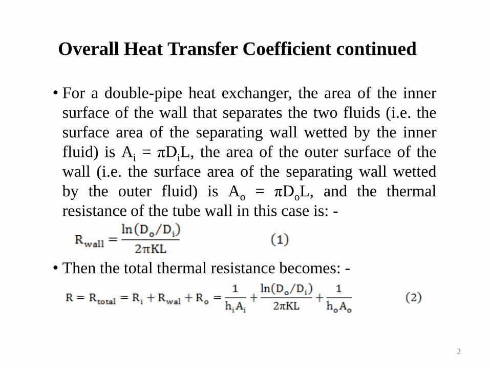
• For a double-pipe heat exchanger, the area of the inner
surface of the wall that separates the two fluids (i.e. the
surface area of the separating wall wetted by the inner
fluid) is Ai = πDiL, the area of the outer surface of the
wall (i.e. the surface area of the separating wall wetted
by the outer fluid) is Ao = πDoL, and the thermal
resistance of the tube wall in this case is: -
• Then the total thermal resistance becomes: -
2
3
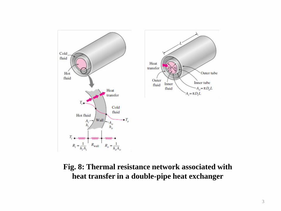
Fig. 8: Thermal resistance network associated with
heat transfer in a double-pipe heat exchanger
Overall Heat Transfer Coefficient continued
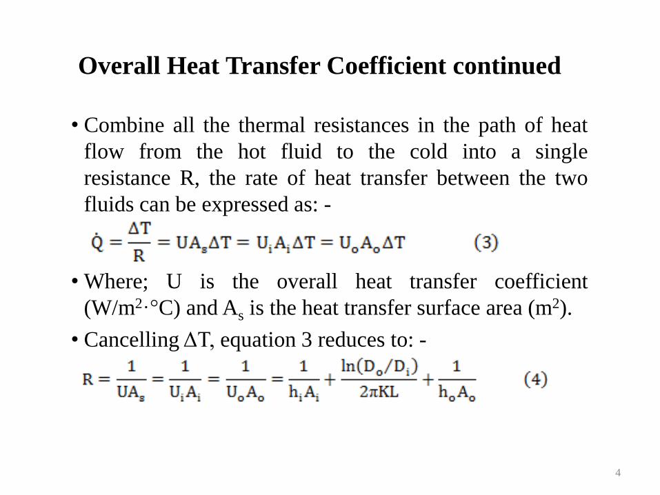
• Combine all the thermal resistances in the path of heat
flow from the hot fluid to the cold into a single
resistance R, the rate of heat transfer between the two
fluids can be expressed as: -
• Where; U is the overall heat transfer coefficient
(W/m2·°C) and As is the heat transfer surface area (m2).
• Cancelling ΔT, equation 3 reduces to: -
4
Overall Heat Transfer Coefficient continued
• There are two overall heat transfer coefficients Ui and Uo
for a heat exchanger because every heat exchanger has
two heat transfer surface areas Ai and Ao, which in
general are not equal to each other. That is; UiAi = UoAo,
and Ui ≠ Uo unless Ai = Ao. Therefore, the overall heat
transfer coefficient U of a heat exchanger is meaningless
unless the area on which it is based is specified.
• When the wall thickness of the tube is small or the
thermal conductivity of the tube material is high, the
thermal resistance of the tube is negligible (Rwall = 0),
and the inner and outer surfaces of the tube are almost
identical (i.e. Ai = Ao = As).
5
Overall Heat Transfer Coefficient continued
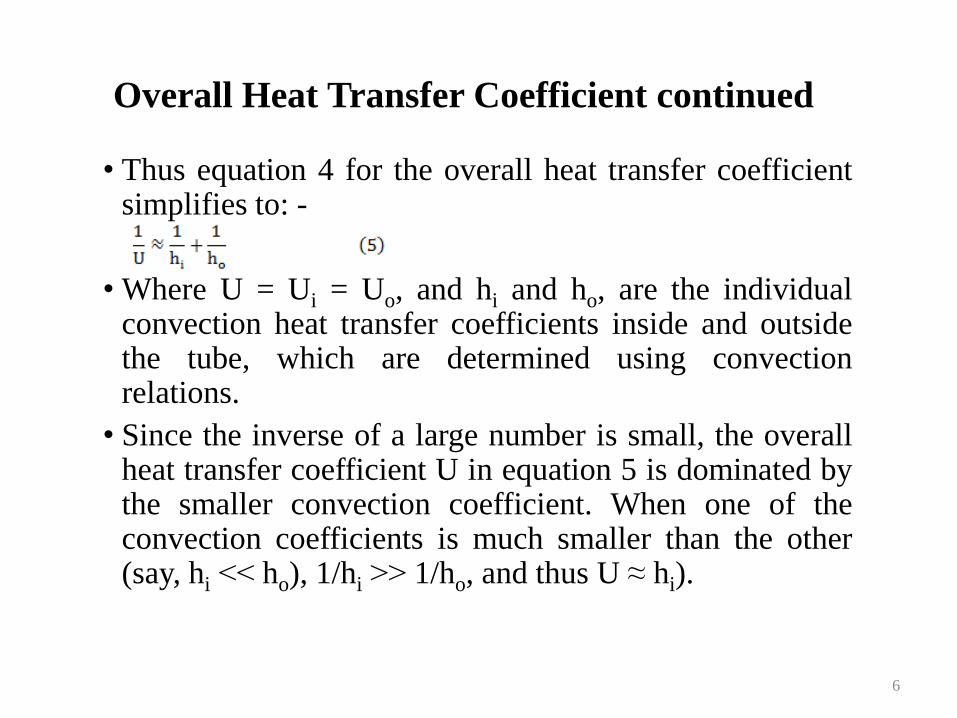
• Thus equation 4 for the overall heat transfer coefficient simplifies to: -
• Where U = Ui = Uo, and hi and ho, are the individual convection heat transfer coefficients inside and outside the tube, which are determined using convection relations.
• Since the inverse of a large number is small, the overall heat transfer coefficient U in equation 5 is dominated by the smaller convection coefficient. When one of the convection coefficients is much smaller than the other (say, hi ˂˂ ho), 1/hi ˃˃ 1/ho, and thus U ≈ hi).
6
Overall Heat Transfer Coefficient continued
• Therefore, the smaller heat transfer coefficient creates a
bottleneck on the path of heat flow and seriously
impedes heat transfer. This situation arises frequently
when one of the fluids is a gas and the other is a liquid.
In such cases, fins are commonly used on the gas side to
enhance the product UAs and thus the heat transfer on
that side.
• Representative values of the overall heat transfer
coefficient U are given in Table 1. The overall heat
transfer coefficient ranges from about 10 W/m2·°C for
gas-to-gas heat exchangers to about 10,000 W/m2·°C for
heat exchangers that involve phase changes.
7
8
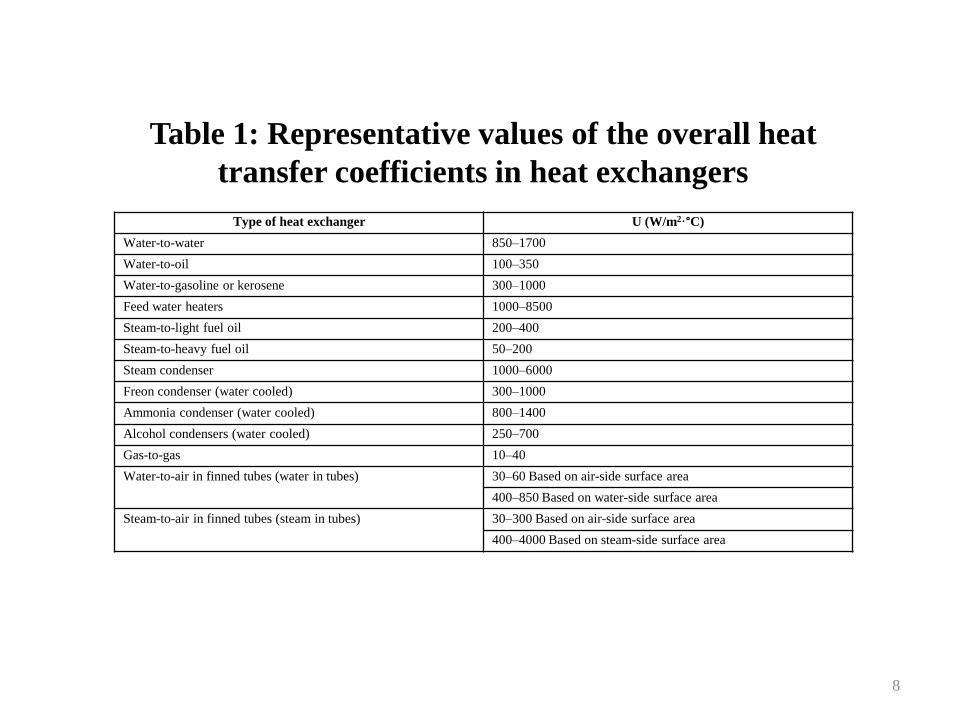
Type of heat exchanger U (W/m2·°C)
Water-to-water 850–1700
Water-to-oil 100–350
Water-to-gasoline or kerosene 300–1000
Feed water heaters 1000–8500
Steam-to-light fuel oil 200–400
Steam-to-heavy fuel oil 50–200
Steam condenser 1000–6000
Freon condenser (water cooled) 300–1000
Ammonia condenser (water cooled) 800–1400
Alcohol condensers (water cooled) 250–700
Gas-to-gas 10–40
Water-to-air in finned tubes (water in tubes) 30–60 Based on air-side surface area
400–850 Based on water-side surface area
Steam-to-air in finned tubes (steam in tubes) 30–300 Based on air-side surface area
400–4000 Based on steam-side surface area
Table 1: Representative values of the overall heat
transfer coefficients in heat exchangers
Overall Heat Transfer Coefficient continued
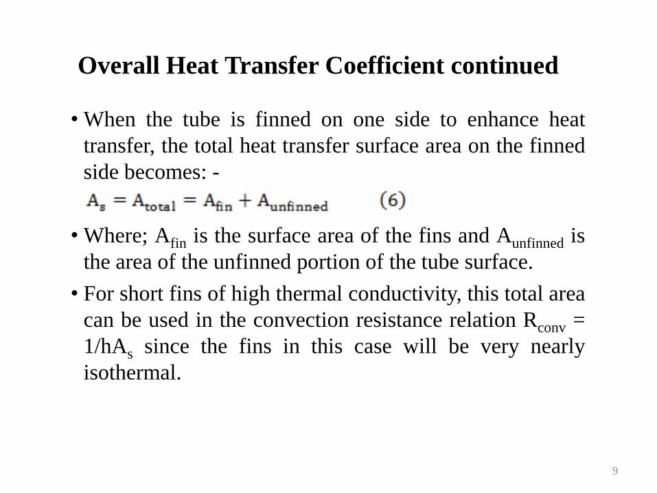
• When the tube is finned on one side to enhance heat
transfer, the total heat transfer surface area on the finned
side becomes: -
• Where; Afin is the surface area of the fins and Aunfinned is
the area of the unfinned portion of the tube surface.
• For short fins of high thermal conductivity, this total area
can be used in the convection resistance relation Rconv =
1/hAs since the fins in this case will be very nearly
isothermal.
9
Overall Heat Transfer Coefficient continued
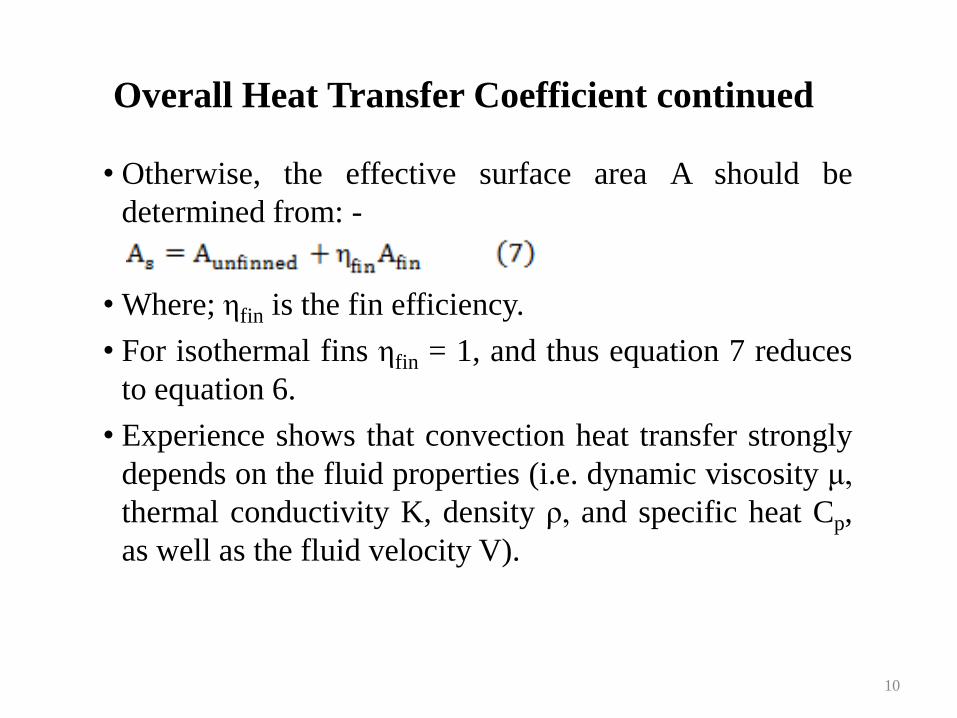
• Otherwise, the effective surface area A should be
determined from: -
• Where; ηfin is the fin efficiency.
• For isothermal fins ηfin = 1, and thus equation 7 reduces
to equation 6.
• Experience shows that convection heat transfer strongly
depends on the fluid properties (i.e. dynamic viscosity μ,
thermal conductivity K, density ρ, and specific heat Cp,
as well as the fluid velocity V).
10
Overall Heat Transfer Coefficient continued
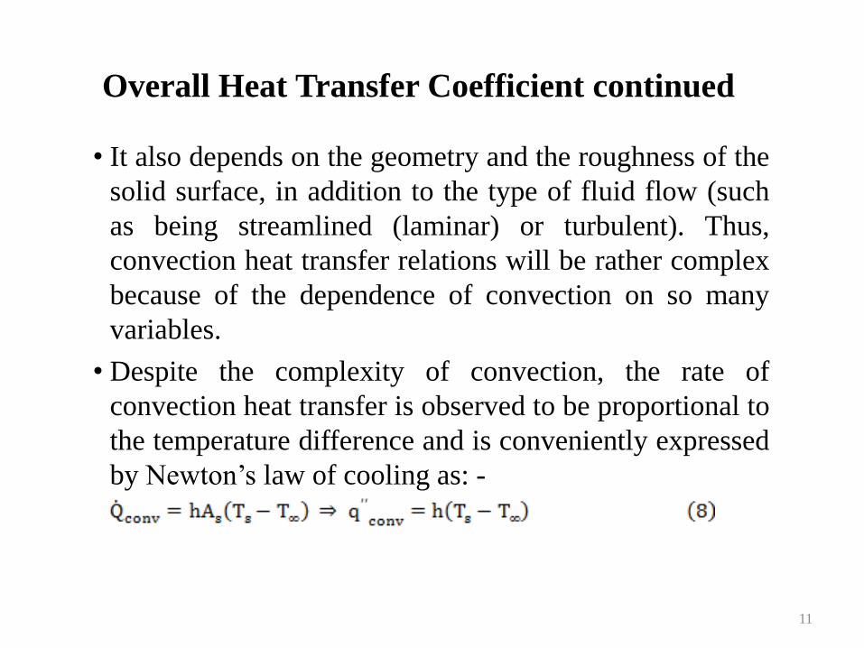
• It also depends on the geometry and the roughness of the
solid surface, in addition to the type of fluid flow (such
as being streamlined (laminar) or turbulent). Thus,
convection heat transfer relations will be rather complex
because of the dependence of convection on so many
variables.
• Despite the complexity of convection, the rate of
convection heat transfer is observed to be proportional to
the temperature difference and is conveniently expressed
by Newton’s law of cooling as: -
11
Overall Heat Transfer Coefficient continued
• Where; h is the convection heat transfer coefficient
defined as the rate of heat transfer between a solid
surface and a fluid per unit surface area per unit
temperature difference (W/m2.°C), As the heat transfer
surface area (m2), Ts the temperature of the surface (°C),
and T∞ the temperature of the fluid sufficiently far from
the surface (°C).
• Regardless of the simple appearance of equation 8, the
convection heat transfer coefficient h is difficult to
determine as convection heat transfer relations are rather
complex because of its dependence on the several
mentioned variables.
12
Overall Heat Transfer Coefficient continued
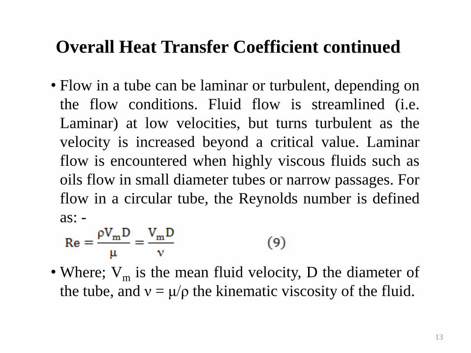
• Flow in a tube can be laminar or turbulent, depending on
the flow conditions. Fluid flow is streamlined (i.e.
Laminar) at low velocities, but turns turbulent as the
velocity is increased beyond a critical value. Laminar
flow is encountered when highly viscous fluids such as
oils flow in small diameter tubes or narrow passages. For
flow in a circular tube, the Reynolds number is defined
as: -
• Where; Vm is the mean fluid velocity, D the diameter of
the tube, and ν = μ/ρ the kinematic viscosity of the fluid.
13
Overall Heat Transfer Coefficient continued
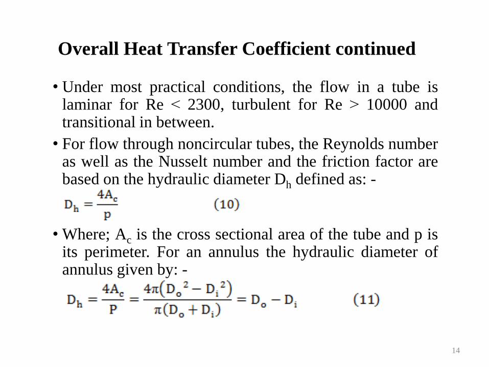
• Under most practical conditions, the flow in a tube is laminar for Re ˂ 2300, turbulent for Re ˃ 10000 and transitional in between.
• For flow through noncircular tubes, the Reynolds number as well as the Nusselt number and the friction factor are based on the hydraulic diameter Dh defined as: -
• Where; Ac is the cross sectional area of the tube and p is its perimeter. For an annulus the hydraulic diameter of annulus given by: -
14
Overall Heat Transfer Coefficient continued
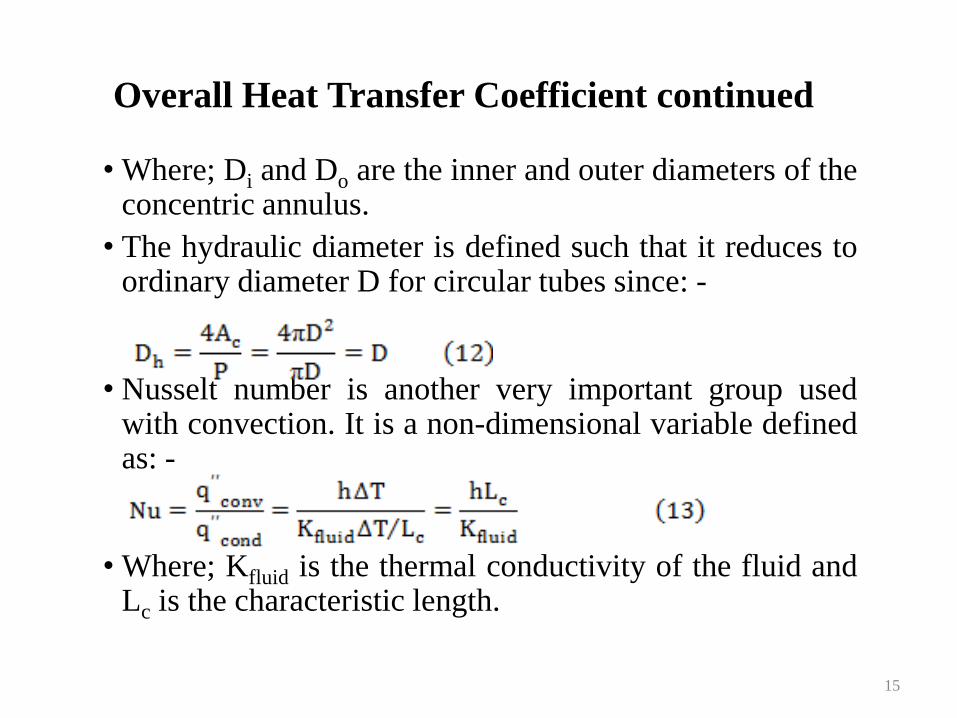
• Where; Di and Do are the inner and outer diameters of the concentric annulus.
• The hydraulic diameter is defined such that it reduces to ordinary diameter D for circular tubes since: -
• Nusselt number is another very important group used with convection. It is a non-dimensional variable defined as: -
• Where; Kfluid is the thermal conductivity of the fluid and Lc is the characteristic length.
15
Overall Heat Transfer Coefficient continued
• The Nusselt number represents the enhancement of heat
transfer through a fluid layer as a result of convection
relative to conduction across the same fluid layer. A
Nusselt number of Nu = 1 for a fluid layer represents
heat transfer across the layer by pure conduction.
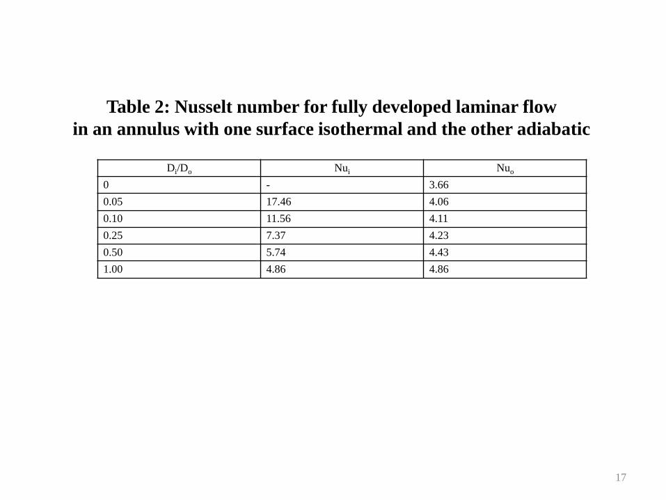
• Annular flow may involve heat transfer on both inner
and outer surfaces and therefore is associated with two
Nusselt numbers: Nui on the inner tube surface and Nuo
on the outer tube surface. The Nusselt numbers for fully
developed laminar flow with one surface isothermal and
the other adiabatic are given in Table 2.
16
17
Di/Do Nui Nuo
0 - 3.66
0.05 17.46 4.06
0.10 11.56 4.11
0.25 7.37 4.23
0.50 5.74 4.43
1.00 4.86 4.86
Table 2: Nusselt number for fully developed laminar flow
in an annulus with one surface isothermal and the other adiabatic
Overall Heat Transfer Coefficient continued
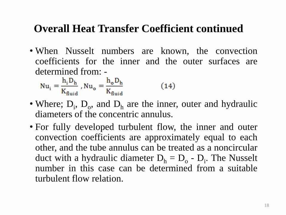
• When Nusselt numbers are known, the convection coefficients for the inner and the outer surfaces are determined from: -
• Where; Di, Do, and Dh are the inner, outer and hydraulic diameters of the concentric annulus.
• For fully developed turbulent flow, the inner and outer convection coefficients are approximately equal to each other, and the tube annulus can be treated as a noncircular duct with a hydraulic diameter Dh = Do - Di. The Nusselt number in this case can be determined from a suitable turbulent flow relation.
18
Overall Heat Transfer Coefficient continued
• Prandtl Number
• The thickness of the thermal boundary layer increases in the flow direction, since the effects of heat transfer are felt at greater distances from the surface further downstream.
• Because the convection heat transfer rate anywhere along the surface is directly related to the temperature gradient at that location, the shape of the temperature profile in the thermal boundary layer dictates the convection heat transfer between a solid surface and the fluid flowing over it. In flow over a heated or cooled surface, both velocity and thermal boundary layers will develop simultaneously.
19
Overall Heat Transfer Coefficient continued
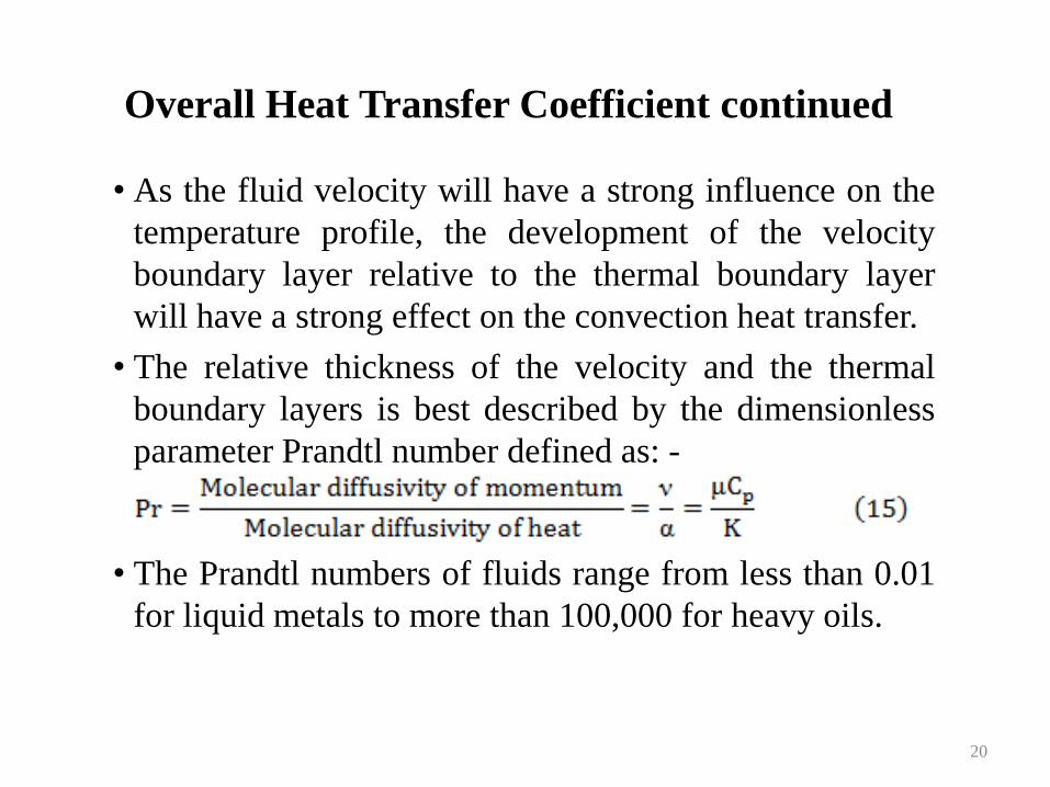
• As the fluid velocity will have a strong influence on the
temperature profile, the development of the velocity
boundary layer relative to the thermal boundary layer
will have a strong effect on the convection heat transfer.
• The relative thickness of the velocity and the thermal
boundary layers is best described by the dimensionless
parameter Prandtl number defined as: -
• The Prandtl numbers of fluids range from less than 0.01
for liquid metals to more than 100,000 for heavy oils.
20
Overall Heat Transfer Coefficient continued
• The Prandtl number of water is in the order of 10. The
Prandtl numbers of gases are about 1 (i.e. both
momentum and heat dissipate through the fluid at about
the same rate).
• Heat diffuses very quickly in liquid metals (Pr ˂˂ 1) and
very slowly in oils (Pr ˃˃ 1) relative to momentum.
Consequently the thermal boundary layer is much
thicker for liquid metals and much thinner for oils
relative to the velocity boundary layer.
21
22
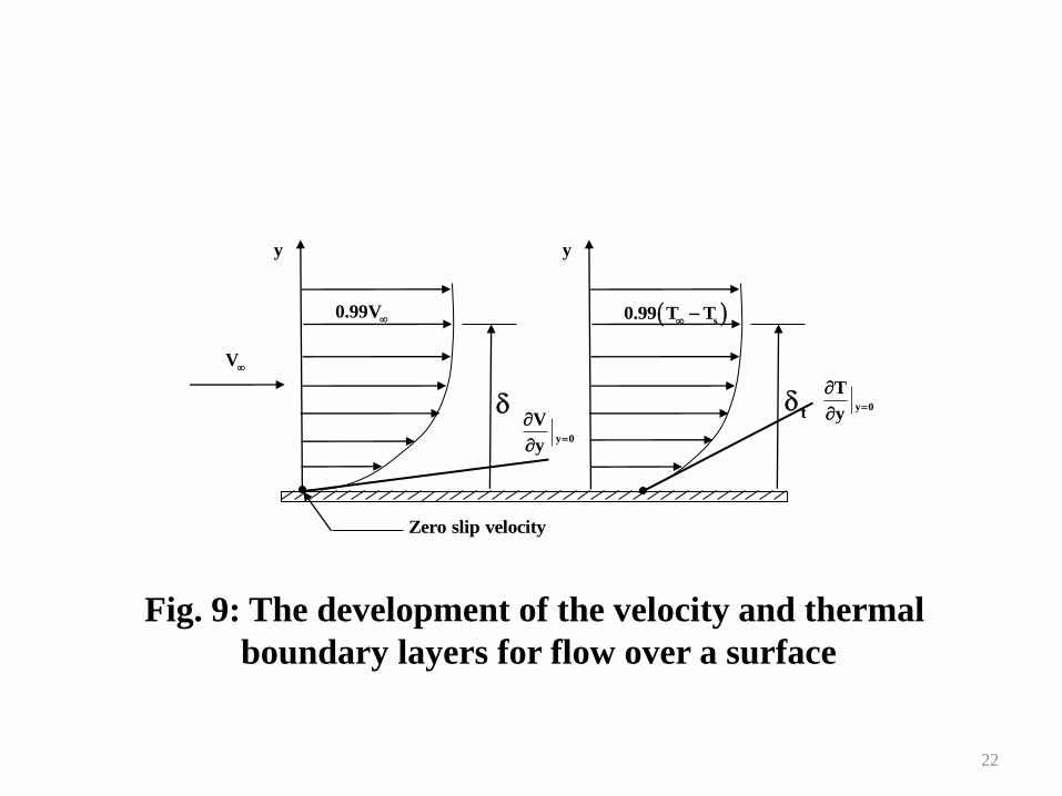
Fig. 9: The development of the velocity and thermal
boundary layers for flow over a surface
V
0.99V
Zero slip velocity
y 0
V
y
y
s0.99 T T
t y 0
T
y
y
Overall Heat Transfer Coefficient continued
• When a fluid is forced to flow over a solid nonporous
surface (i.e. impermeable to the fluid), the fluid in
motion comes to a complete stop at the surface and
assumes a zero velocity relative to the surface (i.e. the
fluid layer in direct contact with the solid surface sticks
to the surface and there is no slip). This phenomenon,
which is due to the viscosity of the fluid, is known as the
no-slip condition. The no-slip condition is responsible
for the development of the velocity profile for flow (i.e.
because of friction between the fluid layers, the layer
that sticks to the wall slows the adjacent fluid layer,
which slows the next layer, and so on).
23
Overall Heat Transfer Coefficient continued
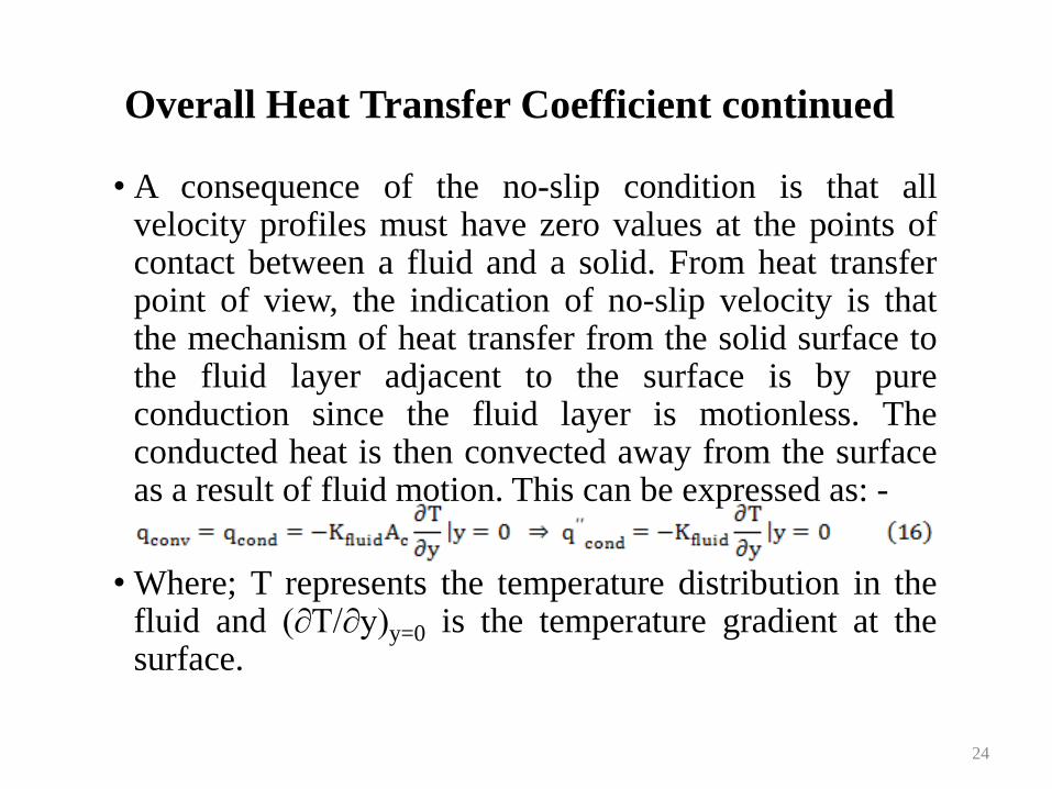
• A consequence of the no-slip condition is that all velocity profiles must have zero values at the points of contact between a fluid and a solid. From heat transfer point of view, the indication of no-slip velocity is that the mechanism of heat transfer from the solid surface to the fluid layer adjacent to the surface is by pure conduction since the fluid layer is motionless. The conducted heat is then convected away from the surface as a result of fluid motion. This can be expressed as: -
• Where; T represents the temperature distribution in the fluid and (∂T/∂y)y=0 is the temperature gradient at the surface.
24
Overall Heat Transfer Coefficient continued
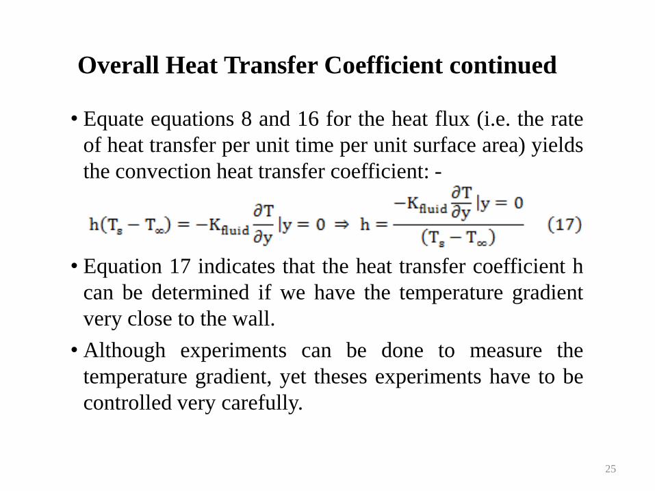
• Equate equations 8 and 16 for the heat flux (i.e. the rate
of heat transfer per unit time per unit surface area) yields
the convection heat transfer coefficient: -
• Equation 17 indicates that the heat transfer coefficient h
can be determined if we have the temperature gradient
very close to the wall.
• Although experiments can be done to measure the
temperature gradient, yet theses experiments have to be
controlled very carefully.
25
Overall Heat Transfer Coefficient continued
• In general, it must be realised that the heat transfer
coefficient is not constant; it is actually a function of
position (i.e. varies along the flow direction due to the
change in the temperature gradient with position).
• In general, except when the flow is fully developed, the
heat transfer coefficients are not the same at the different
positions. Thus in many times, an average value will be
used. The average or mean convection heat transfer
coefficient for a surface is determined by properly
averaging the local convection heat transfer coefficients
over the entire surface.
26
Overall Heat Transfer Coefficient continued
• Thus in many times, an average value will be used. The
average or mean convection heat transfer coefficient for
a surface is determined by properly averaging the local
convection heat transfer coefficients over the entire
surface.
27
Fouling Factor
• The performance of heat exchangers usually deteriorates
with time as a result of accumulation of deposits on heat
transfer surfaces. The layer of deposits represents
additional resistance to heat transfer and causes the rate
of heat transfer in a heat exchanger to decrease. The net
effect of these accumulations on heat transfer is
represented by a fouling factor Rf, which is a measure of
the thermal resistance introduced by fouling.
• The most common type of fouling is the precipitation of
solid deposits in a fluid on the heat transfer surfaces.
28
Fouling Factor
• This type of fouling can be observed by noticing a layer of calcium-based deposits on the inner surfaces a teapot (the surfaces at which boiling occurs) after prolonged use especially in areas where the water is hard. Mineral deposits forming on the inner surfaces of fine tubes in a heat exchanger (Fig. 10) is another example. The scales of such deposits come off by scratching, and the surfaces can be cleaned of such deposits by chemical treatment.
• To avoid the detrimental effect these deposits may have on the flow passage area and the heat transfer, water in power and process plants is extensively treated and its solid contents are removed before it is allowed to circulate through the system.
29
30
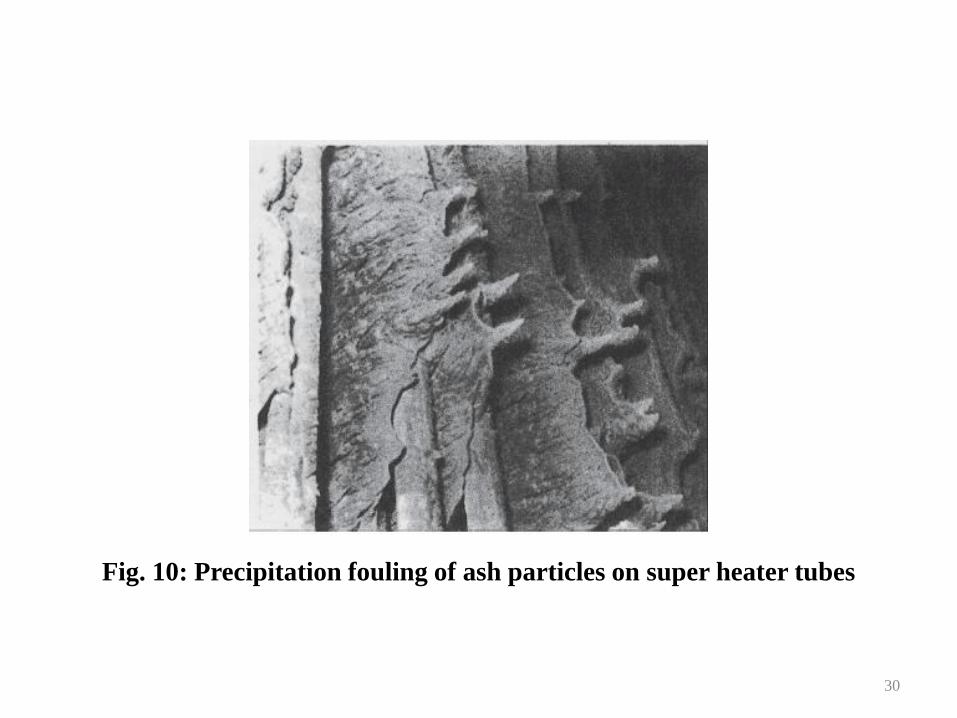
Fig. 10: Precipitation fouling of ash particles on super heater tubes
Fouling Factor continued
• The solid ash particles in the flue gases accumulating on
the surfaces of air pre-heaters create similar problems.
• Another form of fouling, which is common in chemical
process industry, is corrosion and other chemical fouling
in which the surfaces are fouled by the accumulation of
the products of chemical reactions on the surfaces.
Corrosion fouling can be avoided by coating metal pipes
with glass or using plastic pipes instead of metal ones.
• Heat exchangers may also be fouled by the growth of
algae (biological fouling) in warm fluids and can be
prevented by chemical treatment.
31
Fouling Factor continued
• Fouling should be considered in the design and selection of heat exchangers in applications where it is likely to occur (i.e. select a larger and thus more expensive heat exchanger to ensure that it meets the design heat transfer requirements even after fouling occurs).
• The periodic cleaning of heat exchangers and the resulting down time are additional penalties associated with fouling.
• The fouling factor is obviously zero for a new heat exchanger and increases with time as the solid deposits build up on the heat exchanger surface. The fouling factor depends on the operating temperature and the velocity of the fluids, as well as the length of service.
32
Fouling Factor continued
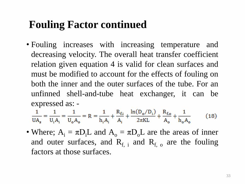
• Fouling increases with increasing temperature and
decreasing velocity. The overall heat transfer coefficient
relation given equation 4 is valid for clean surfaces and
must be modified to account for the effects of fouling on
both the inner and the outer surfaces of the tube. For an
unfinned shell-and-tube heat exchanger, it can be
expressed as: -
• Where; Ai = πDiL and Ao = πDoL are the areas of inner
and outer surfaces, and Rf, i and Rf, o are the fouling
factors at those surfaces.
33
34
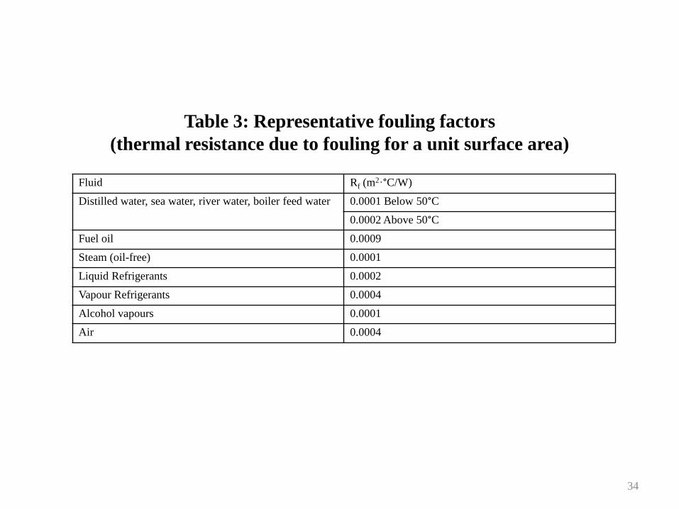
Fluid Rf (m2·°C/W)
Distilled water, sea water, river water, boiler feed water 0.0001 Below 50°C
0.0002 Above 50°C
Fuel oil 0.0009
Steam (oil-free) 0.0001
Liquid Refrigerants 0.0002
Vapour Refrigerants 0.0004
Alcohol vapours 0.0001
Air 0.0004
Table 3: Representative fouling factors
(thermal resistance due to fouling for a unit surface area)
Fouling Factor continued
• Representative values of fouling factors are given in
Table 3. More comprehensive tables of fouling factors
are available in handbooks. Considerable uncertainty
exists in representative values of fouling factors available
in handbooks, and they should be used as a guide in
selection and evaluation of heat exchangers to account
for the effects of anticipated fouling on heat transfer.
• Most fouling factors are of the order of 10-4 m2·°C/W,
which is equivalent to the thermal resistance of 0.2 mm
thick limestone layer (K = 2.9 W/m·°C) per unit surface
area.
35
Fouling Factor continued
• Therefore, in the absence of specific data, the surfaces
can be assumed to be coated with 0.2 mm of limestone
as a starting point to account for the effects of fouling.
36
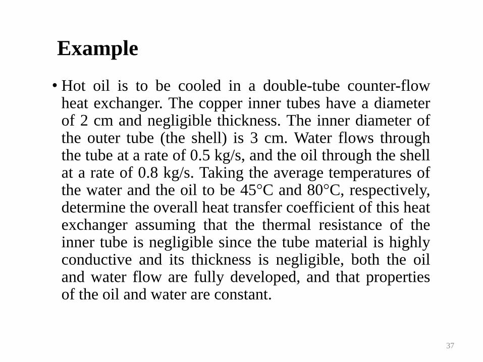
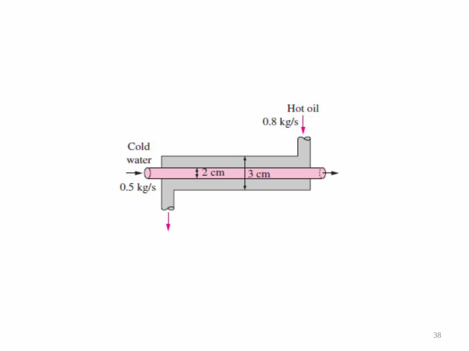
Example
• Hot oil is to be cooled in a double-tube counter-flow heat exchanger. The copper inner tubes have a diameter of 2 cm and negligible thickness. The inner diameter of the outer tube (the shell) is 3 cm. Water flows through the tube at a rate of 0.5 kg/s, and the oil through the shell at a rate of 0.8 kg/s. Taking the average temperatures of the water and the oil to be 45°C and 80°C, respectively, determine the overall heat transfer coefficient of this heat exchanger assuming that the thermal resistance of the inner tube is negligible since the tube material is highly conductive and its thickness is negligible, both the oil and water flow are fully developed, and that properties of the oil and water are constant.
37
38
Example Solution
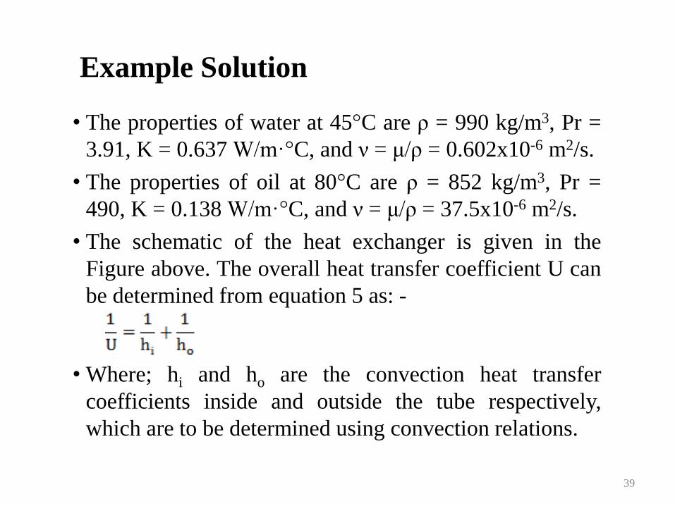
• The properties of water at 45°C are ρ = 990 kg/m3, Pr =
3.91, K = 0.637 W/m·°C, and ν = μ/ρ = 0.602x10⁻⁶ m2/s.
• The properties of oil at 80°C are ρ = 852 kg/m3, Pr =
490, K = 0.138 W/m·°C, and ν = μ/ρ = 37.5x10⁻⁶ m2/s.
• The schematic of the heat exchanger is given in the
Figure above. The overall heat transfer coefficient U can
be determined from equation 5 as: -
• Where; hi and ho are the convection heat transfer
coefficients inside and outside the tube respectively,
which are to be determined using convection relations.
39
Example Solution continued
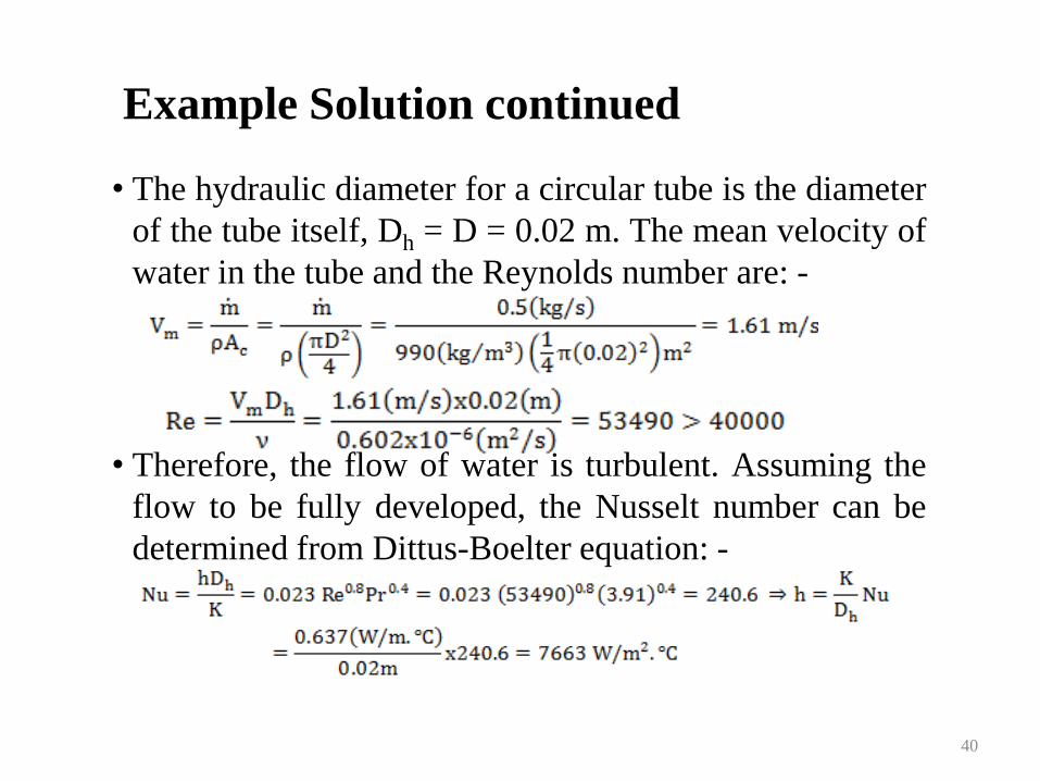
• The hydraulic diameter for a circular tube is the diameter
of the tube itself, Dh = D = 0.02 m. The mean velocity of
water in the tube and the Reynolds number are: -
• Therefore, the flow of water is turbulent. Assuming the
flow to be fully developed, the Nusselt number can be
determined from Dittus-Boelter equation: -
40
Example Solution continued
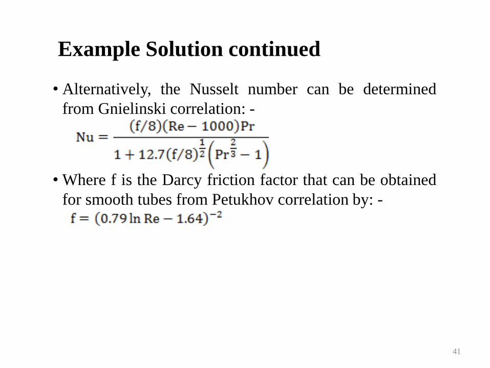
• Alternatively, the Nusselt number can be determined
from Gnielinski correlation: -
• Where f is the Darcy friction factor that can be obtained
for smooth tubes from Petukhov correlation by: -
41
Example Solution continued
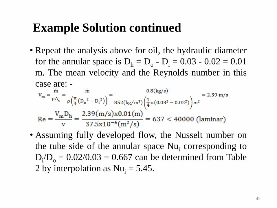
• Repeat the analysis above for oil, the hydraulic diameter
for the annular space is Dh = Do - Di = 0.03 - 0.02 = 0.01
m. The mean velocity and the Reynolds number in this
case are: -
• Assuming fully developed flow, the Nusselt number on
the tube side of the annular space Nui corresponding to
Di/Do = 0.02/0.03 = 0.667 can be determined from Table
2 by interpolation as Nui = 5.45.
42
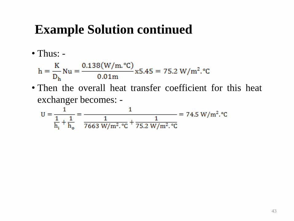
Example Solution continued
• Thus: -
• Then the overall heat transfer coefficient for this heat
exchanger becomes: -
43