
Heat Transfer Enhancement in A Circular Tube having ...Keywords –Twist tape, heat transfer...
6
Heat Transfer Enhancement in A Circular Tube having Integral Helical Swirl and Fitted with Twisted-Tape Abdul Muthalif.A Department of Mechanical Engineering P.A. college of engineering and technology, Pollachi, Tamil Nadu, India Parthasarathy.M Department of Mechanical Engineering P.A. college of engineering and technology, Pollachi, Tamil Nadu, India Abstract- Heat exchangers have several industrial and engineering applications. The design procedure of heat exchangers is quite complicated, as it needs exact analysis of heat transfer rate and pressure drop estimations apart from issues such as long term performance and the economic aspect of the equipment. Whenever inserts are used for the heat transfer enhancement, along with the increase in the heat transfer rate, the pressure drop also increases. This increase in pressure drop increases the pumping cost. Therefore any augmentation device should optimize between the benefits due to the increased heat transfer coefficient and the higher cost involved because of the increased frictional losses. The present paper includes various heat transfer augmentation techniques. A literature review of heat transfer augmentation using passive techniques has been included. Experimental work on heat transfer augmentation using twisted tape and a new kind of insert called twisted angles is carried out. Inserts when placed in the path of the flow of the liquid, create a high degree of turbulence resulting in an increase in the heat transfer Rate and the pressure drop. The work includes the determination of friction factor and heat transfer coefficient for various twisted tapes and twisted angles having different twist ratios. This project focused on that with an increase in Reynolds number (Re), the heat transfer coefficient where as the friction factor decrease. Keywords –Twist tape, heat transfer enhancement, inserts. I. INTRODUCTION In this paper heat transfer of heat transfer equipment such as heat exchangers dealing with fluids of low thermal conductivity (gases and oils) and desalination plants, there is a need to increase the heat transfer rate. The heat transfer rate can be improved by introducing a disturbance in the fluid flow (breaking the viscous and thermal boundary layers), but in the process pumping power may increase significantly and ultimately the pumping cost becomes high. Therefore, to achieve a desired heat transfer rate in a Existing heat exchanger at an economic pumping power, several techniques have been proposed in recent years and are discussed and concluded in the following sections. II. LITERATURE SURVEY [1] P. Farrell, K. Wert, R.L. Webb(1991), tested one fully ribbed and two broken ribbed flat radiator tube. They obtained friction factors for 200 < Re < 11,000.However, the heat transfer coefficients were obtained only for turbulent flow with Re > 2000. The broken-ribbed tube with the highest e/Dh yielded the highest heat transfer coefficient as well as the highest friction factor.[2] C.O. Olsson, B. Sunden(1996) tested two ribbed radiator tubes with airflow. The air heat transfer data were taken with constant wall temperature and the data provide the axially averaged heat transfer coefficient over the tube length. The enhanced tubes showed higher friction factors than the smooth tube in both laminar and turbulent regions. However, as the Reynolds number decreased in the strictly laminar region, the friction factors tended to converge and approach the smooth tube value. Also, the laminar– turbulent transition Reynolds number decreased as the friction factor increased. Similar to the friction behavior, the Colburn j factors also tended to converge at low Reynolds numbers, and approached the smooth tube value. However, in contrast to the friction factors, the j factors did not show a clear laminar–turbulent transition.[3] C.O. Olsson, B. Sunden, (1998) investigated the effect of rib configurations for the multiple V-ribbed channel. Helical screw-tape inserts as shown in Fig. 2.1 cause the flow to spiral along the tube length. Twisted tapes are similar to International Journal of Latest Trends in Engineering and Technology (IJLTET) Vol. 4 Issue 4 November 2014 31 ISSN: 2278-621X
Transcript of Heat Transfer Enhancement in A Circular Tube having ...Keywords –Twist tape, heat transfer...
Heat Transfer Enhancement in A Circular Tube having Integral Helical Swirl and Fitted with
Twisted-Tape Abdul Muthalif.A
Department of Mechanical EngineeringP.A. college of engineering and technology, Pollachi, Tamil Nadu, India
Parthasarathy.MDepartment of Mechanical Engineering
P.A. college of engineering and technology, Pollachi, Tamil Nadu, India
Abstract- Heat exchangers have several industrial and engineering applications. The design procedure of heat exchangers is quite complicated, as it needs exact analysis of heat transfer rate and pressure drop estimations apart from issues such as long term performance and the economic aspect of the equipment. Whenever inserts are used for the heat transfer enhancement, along with the increase in the heat transfer rate, the pressure drop also increases. This increase in pressure drop increases the pumping cost. Therefore any augmentation device should optimize between the benefits due to the increased heat transfer coefficient and the higher cost involved because of the increased frictional losses. The present paper includes various heat transfer augmentation techniques. A literature review of heat transfer augmentation using passive techniques has been included. Experimental work on heat transfer augmentation using twisted tape and a new kind of insert called twisted angles is carried out. Inserts when placed in the path of the flow of the liquid, create a high degree of turbulence resulting in an increase in the heat transfer Rate and the pressure drop. The work includes the determination of friction factor and heat transfer coefficient for various twisted tapes and twisted angles having different twist ratios. This project focused on that with an increase in Reynolds number (Re), the heat transfer coefficient where as the friction factor decrease.
Keywords –Twist tape, heat transfer enhancement, inserts.
I. INTRODUCTION
In this paper heat transfer of heat transfer equipment such as heat exchangers dealing with fluids of low thermal conductivity (gases and oils) and desalination plants, there is a need to increase the heat transfer rate. The heat transfer rate can be improved by introducing a disturbance in the fluid flow (breaking the viscous and thermal boundary layers), but in the process pumping power may increase significantly and ultimately the pumping cost becomes high. Therefore, to achieve a desired heat transfer rate in a Existing heat exchanger at an economic pumping power, several techniques have been proposed in recent years and are discussed and concluded in the following sections.
II. LITERATURE SURVEY
[1] P. Farrell, K. Wert, R.L. Webb(1991), tested one fully ribbed and two broken ribbed flat radiator tube. They obtained friction factors for 200 < Re < 11,000.However, the heat transfer coefficients were obtained only for turbulent flow with Re > 2000. The broken-ribbed tube with the highest e/Dh yielded the highest heat transfer coefficient as well as the highest friction factor.[2] C.O. Olsson, B. Sunden(1996) tested two ribbed radiator tubes with airflow. The air heat transfer data were taken with constant wall temperature and the data provide the axially averaged heat transfer coefficient over the tube length. The enhanced tubes showed higher friction factors than the smooth tube in both laminar and turbulent regions. However, as the Reynolds number decreased in the strictly laminar region, the friction factors tended to converge and approach the smooth tube value. Also, the laminar–turbulent transition Reynolds number decreased as the friction factor increased. Similar to the friction behavior, the Colburn j factors also tended to converge at low Reynolds numbers, and approached the smooth tube value. However, in contrast to the friction factors, the j factors did not show a clear laminar–turbulent transition.[3] C.O. Olsson, B. Sunden, (1998) investigated the effect of rib configurations for the multiple V-ribbed channel. Helical screw-tape inserts as shown in Fig. 2.1 cause the flow to spiral along the tube length. Twisted tapes are similar to
International Journal of Latest Trends in Engineering and Technology (IJLTET)
Vol. 4 Issue 4 November 2014 31 ISSN: 2278-621X
helical screw-tape inserts. Continuous twisted-tape as shown in Fig. 2.2 has been extensively investigated. Variants of twisted-tape that have been\evaluated include short sections of twisted tapes at the tube inlet, or periodically spaced along the tube length [4] S.K. Saha,A.Dutta (2001), have observed that, for regularly spaced twisted-tape elements, thermo hydraulic performance of twisted tapes with multiple twists in the tape module is not much different from that with single twist in the tape module. Twisted tapes with gradually decreasing pitch perform worse than their uniform-pitch counterparts.[5] A.G. Patil (2000), have worked with varying width twisted-tape inserts for which both friction factor and Nusselt number are lower than those with full width twisted tapes.
III. EXPERIMENTAL PROCEDURES:
A.About the inserts:The insert used for the experiment are twisted aluminium angles and stainless steel twisted tapes. While
much literature can be found about passive heat transfer augmentation using twisted tapes as mentioned earlier, twisted aluminium angles are a new kind of insert where no such experiments have been done thus giving us ample room for experimental studies. The present work deals with finding the friction factor and the heat transfer coefficient for the twisted angles with twist ratios and twisted tapes with twist and comparing those results with that of smooth tube and among themselves.B.Fabrication of inserts:
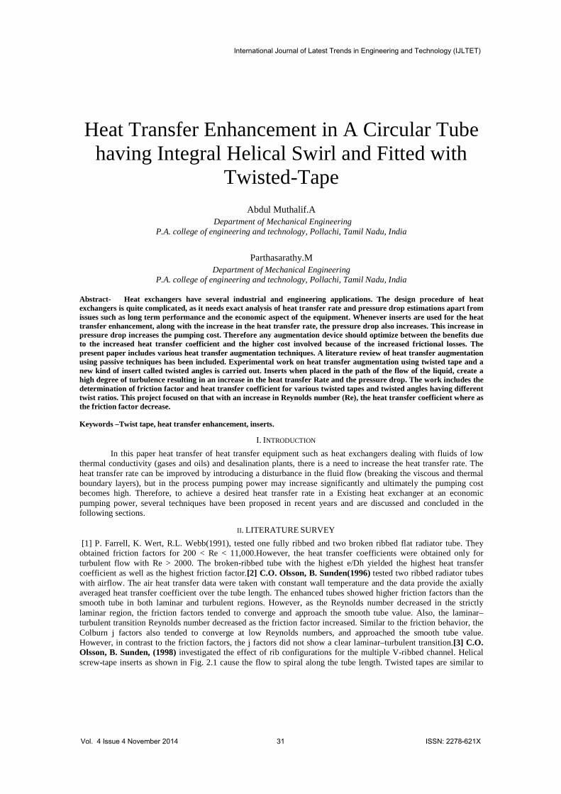
Four angle tapes with varying twist ratios were fabricated as shown in The end portions of the fabricated tapes were cut and drilled to join the tapes by thin high tension wires. Three tapes with the same twist ratio and twist in the same direction were joined to give a length of around 2.95 m, which was sufficient for the heat exchanger used for the experimental study. The twisted tapes are shown in
IV.EXPERIMENTAL SETUP
A description of the experimental setup is presented with a Discussion of the experimental procedure
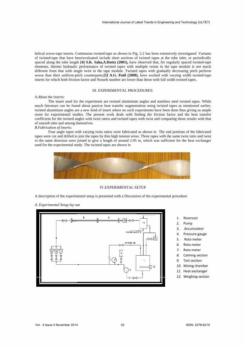
A. Experimental Setup lay out
1. Reservoir 2. Pump 3. Accumulator 4. Pressure gauge 5. Roto meter 6. Roto meter 7. Roto meter 8. Calming section 9. Test section 10. Mixing chamber 11. Heat exchanger 12. Weighing section
International Journal of Latest Trends in Engineering and Technology (IJLTET)
Vol. 4 Issue 4 November 2014 32 ISSN: 2278-621X
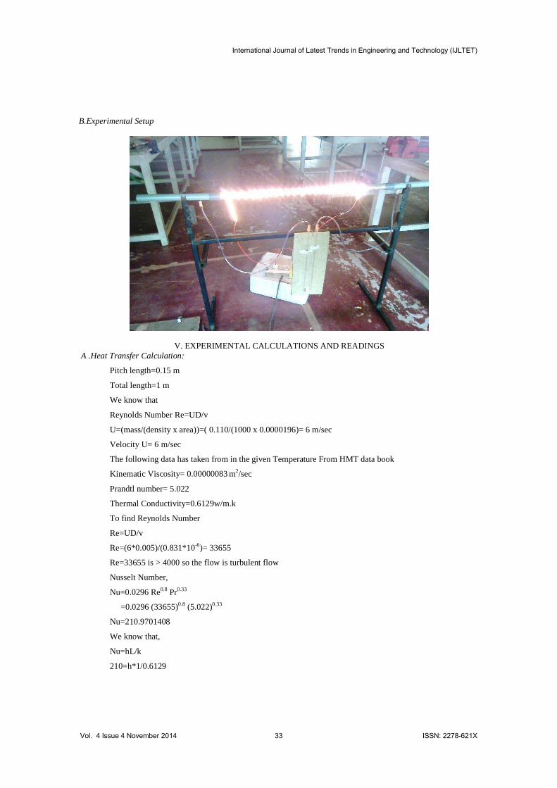
B.Experimental Setup
V. EXPERIMENTAL CALCULATIONS AND READINGSA .Heat Transfer Calculation:
Pitch length=0.15 m
Total length=1 m
We know that
Reynolds Number Re=UD/v
U=(mass/(density x area))=( 0.110/(1000 x 0.0000196)= 6 m/sec
Velocity U= 6 m/sec
The following data has taken from in the given Temperature From HMT data book
Kinematic Viscosity= 0.00000083 m2/sec
Prandtl number= 5.022
Thermal Conductivity=0.6129w/m.k
To find Reynolds Number
Re=UD/v
Re=(6*0.005)/(0.831*10-6)= 33655
Re=33655 is > 4000 so the flow is turbulent flow
Nusselt Number,
Nu=0.0296 Re0.8 Pr0.33
=0.0296 (33655)0.8 (5.022)0.33
Nu=210.9701408
We know that,
Nu=hL/k
210=h*1/0.6129
International Journal of Latest Trends in Engineering and Technology (IJLTET)
Vol. 4 Issue 4 November 2014 33 ISSN: 2278-621X

h=3359 w/m2 k
Heat transfer Q=h A (T2-T1) watts
Q=3359 * 0.157 (40-32)
Q=421.9402815 Watts
Heat transfer Q=mass*specific Heat* (T2-T1) watts
Q= 0.110*4186*(40-32) watts
Q= 3667 Watts
Q=hA(T2-T1)
H=Q/(A*(T2-T1) w/m2K
H=3667/(3.14*0.05*(40-32) w/m2K
H= 2919.5 w/m2K
Pressure Drop Calculation:
Manometer Reading =4.1 cm
- -h2/100)
P=(1600-1000)*9.81*(4.1/100)
P=241.326 N/m2
VI.RESULTS AND DISCUSSION
A. Pressure Drop Results:
1) it was observed that for Re> 20000 i.e., in turbulent region P is nearly equal to 1000 N/m2. For this observed height difference in the manometer was very small, But resulting in a larger deviation in Pitch Value 0.1 m around 1500 N/m2.
2) Pressure drop value varies as per the order=
B.Heat Transfer Results:
Pitch value = 0.1m > 0.15m > 0.175m > internal thread
International Journal of Latest Trends in Engineering and Technology (IJLTET)
Vol. 4 Issue 4 November 2014 34 ISSN: 2278-621X
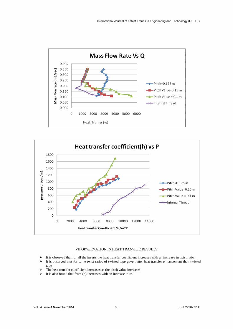
VII.OBSERVATION IN HEAT TRANSFER RESULTS:
Ø It is observed that for all the inserts the heat transfer coefficient increases with an increase in twist ratioØ It is observed that for same twist ratios of twisted tape gave better heat transfer enhancement than twisted
tapeØ The heat transfer coefficient increases as the pitch value increasesØ It is also found that from (h) increases with an increase in re.
International Journal of Latest Trends in Engineering and Technology (IJLTET)
Vol. 4 Issue 4 November 2014 35 ISSN: 2278-621X
Ø It is observed that for internal threads having very low heat transfer co efficient for same pressure drop and mass flow rate.
Ø The pitch value having 0.1 m highest degree of pressure drops so it consumes more power rather than others.
Ø In the fig no1 of heat transfer results up to 0.2 kg/sec the heat transfer co efficient is decreasing increasing after that it is increasing considerably
Ø In the same fig no 1 in the heat transfer results the pitch value 0.1 m gives more heat transfer compared than the others but poor in flow rate
Ø Internal threads are very poor in heat transfer compared than others but give more flow rate and low friction.
VII.CONCLUSION
Ø The pressure drop and the heat transfer coefficient increase as the degree of twist in the tapes on increasing.
Ø The pressure drop and the heat transfer coefficient decreases as the pitch value on tapes increasing.Ø For almost the same twist ratio show greater friction factor and heat transfer coefficient than, because of
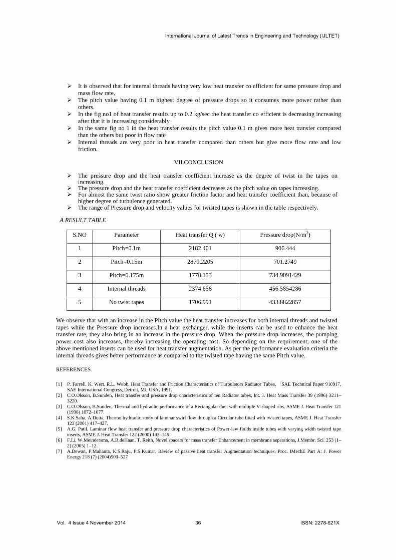
higher degree of turbulence generated. Ø The range of Pressure drop and velocity values for twisted tapes is shown in the table respectively.
A.RESULT TABLE
S.NO Parameter Heat transfer Q ( w) Pressure drop(N/m2)
1 Pitch=0.1m 2182.401 906.444
2 Pitch=0.15m 2879.2205 701.2749
3 Pitch=0.175m 1778.153 734.9091429
4 Internal threads 2374.658 456.5854286
5 No twist tapes 1706.991 433.8822857
We observe that with an increase in the Pitch value the heat transfer increases for both internal threads and twisted tapes while the Pressure drop increases.In a heat exchanger, while the inserts can be used to enhance the heat transfer rate, they also bring in an increase in the pressure drop. When the pressure drop increases, the pumping power cost also increases, thereby increasing the operating cost. So depending on the requirement, one of the above mentioned inserts can be used for heat transfer augmentation. As per the performance evaluation criteria the internal threads gives better performance as compared to the twisted tape having the same Pitch value.
REFERENCES
[1] P. Farrell, K. Wert, R.L. Webb, Heat Transfer and Friction Characteristics of Turbulators Radiator Tubes, SAE Technical Paper 910917, SAE International Congress, Detroit, MI, USA, 1991.
[2] C.O.Olsson, B.Sunden, Heat transfer and pressure drop characteristics of ten Radiator tubes, Int. J. Heat Mass Transfer 39 (1996) 3211–3220.
[3] C.O.Olsson, B.Sunden, Thermal and hydraulic performance of a Rectangular duct with multiple V-shaped ribs, ASME J. Heat Transfer 121 (1998) 1072–1077.
[4] S.K.Saha, A.Dutta, Thermo hydraulic study of laminar swirl flow through a Circular tube fitted with twisted tapes, ASME J. Heat Transfer 123 (2001) 417–427.
[5] A.G. Patil, Laminar flow heat transfer and pressure drop characteristics of Power-law fluids inside tubes with varying width twisted tape inserts, ASME J. Heat Transfer 122 (2000) 143–149.
[6] F.Li, W.Meindersma, A.B.deHaan, T. Reith, Novel spacers for mass transfer Enhancement in membrane separations, J.Membr. Sci. 253 (1–2) (2005) 1–12.
[7] A.Dewan, P.Mahanta, K.S.Raju, P.S.Kumar, Review of passive heat transfer Augmentation techniques, Proc. IMechE Part A: J. Power Energy 218 (7) (2004)509–527
International Journal of Latest Trends in Engineering and Technology (IJLTET)
Vol. 4 Issue 4 November 2014 36 ISSN: 2278-621X