
THE NATIONAL SHIPBUILDING RESEARCH PROGRAM Shipyard, Philadelphia, PA ABSTRACT The Zone Logic...
24
SHIP PRODUCTION COMMITTEE FACILITIES AND ENVIRONMENTAL EFFECTS SURFACE PREPARATION AND COATINGS DESIGN/PRODUCTION INTEGRATION HUMAN RESOURCE INNOVATION MARINE INDUSTRY STANDARDS WELDING INDUSTRIAL ENGINEERING EDUCATION AND TRAINING THE NATIONAL SHIPBUILDING RESEARCH PROGRAM August 1988 NSRP 0298 1988 Ship Production Symposium Paper No. 2B: An Integrated CAD/CAM Network for Work Packaging Development and Database Management U.S. DEPARTMENT OF THE NAVY CARDEROCK DIVISION, NAVAL SURFACE WARFARE CENTER
Transcript of THE NATIONAL SHIPBUILDING RESEARCH PROGRAM Shipyard, Philadelphia, PA ABSTRACT The Zone Logic...

SHIP PRODUCTION COMMITTEEFACILITIES AND ENVIRONMENTAL EFFECTSSURFACE PREPARATION AND COATINGSDESIGN/PRODUCTION INTEGRATIONHUMAN RESOURCE INNOVATIONMARINE INDUSTRY STANDARDSWELDINGINDUSTRIAL ENGINEERINGEDUCATION AND TRAINING
THE NATIONALSHIPBUILDINGRESEARCHPROGRAM
August 1988NSRP 0298
1988 Ship Production Symposium
Paper No. 2B:An Integrated CAD/CAM Networkfor Work Packaging Development and Database Management
U.S. DEPARTMENT OF THE NAVYCARDEROCK DIVISION,NAVAL SURFACE WARFARE CENTER

Report Documentation Page Form ApprovedOMB No. 0704-0188
Public reporting burden for the collection of information is estimated to average 1 hour per response, including the time for reviewing instructions, searching existing data sources, gathering andmaintaining the data needed, and completing and reviewing the collection of information. Send comments regarding this burden estimate or any other aspect of this collection of information,including suggestions for reducing this burden, to Washington Headquarters Services, Directorate for Information Operations and Reports, 1215 Jefferson Davis Highway, Suite 1204, ArlingtonVA 22202-4302. Respondents should be aware that notwithstanding any other provision of law, no person shall be subject to a penalty for failing to comply with a collection of information if itdoes not display a currently valid OMB control number.
1. REPORT DATE AUG 1988
2. REPORT TYPE N/A
3. DATES COVERED -
4. TITLE AND SUBTITLE The National Shipbuilding Research Program: 1988 Ship ProductionSymposium Paper No. 2B: An Integrated CAD/CAM Network for WorkPackaging Development and Database Management
5a. CONTRACT NUMBER
5b. GRANT NUMBER
5c. PROGRAM ELEMENT NUMBER
6. AUTHOR(S) 5d. PROJECT NUMBER
5e. TASK NUMBER
5f. WORK UNIT NUMBER
7. PERFORMING ORGANIZATION NAME(S) AND ADDRESS(ES) Naval Surface Warfare Center CD Code 2230 - Design Integration ToolsBuilding 192 Room 128 9500 MacArthur Blvd Bethesda, MD 20817-5700
8. PERFORMING ORGANIZATIONREPORT NUMBER
9. SPONSORING/MONITORING AGENCY NAME(S) AND ADDRESS(ES) 10. SPONSOR/MONITOR’S ACRONYM(S)
11. SPONSOR/MONITOR’S REPORT NUMBER(S)
12. DISTRIBUTION/AVAILABILITY STATEMENT Approved for public release, distribution unlimited
13. SUPPLEMENTARY NOTES
14. ABSTRACT
15. SUBJECT TERMS
16. SECURITY CLASSIFICATION OF: 17. LIMITATION OF ABSTRACT
SAR
18. NUMBEROF PAGES
23
19a. NAME OFRESPONSIBLE PERSON
a. REPORT unclassified
b. ABSTRACT unclassified
c. THIS PAGE unclassified
Standard Form 298 (Rev. 8-98) Prescribed by ANSI Std Z39-18

DISCLAIMER
These reports were prepared as an account of government-sponsored work. Neither theUnited States, nor the United States Navy, nor any person acting on behalf of the UnitedStates Navy (A) makes any warranty or representation, expressed or implied, with respectto the accuracy, completeness or usefulness of the information contained in this report/manual, or that the use of any information, apparatus, method, or process disclosed in thisreport may not infringe privately owned rights; or (B) assumes any liabilities with respect tothe use of or for damages resulting from the use of any information, apparatus, method, orprocess disclosed in the report. As used in the above, “Persons acting on behalf of theUnited States Navy” includes any employee, contractor, or subcontractor to the contractorof the United States Navy to the extent that such employee, contractor, or subcontractor tothe contractor prepares, handles, or distributes, or provides access to any informationpursuant to his employment or contract or subcontract to the contractor with the UnitedStates Navy. ANY POSSIBLE IMPLIED WARRANTIES OF MERCHANTABILITY AND/ORFITNESS FOR PURPOSE ARE SPECIFICALLY DISCLAIMED.

THE SOCIETY OF NAVAL ARCHITECTS AND MARINE ENGINEERS601 Pavonia Avenue, Jersey City, NJ 07306Paper presented at the NSRP 1988 Ship Production Symposium,
Edgewater Inn. SeattIe. Washington. August 24-26.1988
An Integrated CAD/CAM Network for Work PackagingDevelopment and Database Management No. 2B
LCDR M. S. O’Hare, USN, Member, and LT M. J. Anderson, USN, Visitor, Philadelphia NavalShipyard, Philadelphia, PA
ABSTRACT
The Zone Logic Technology CAD/CAM and networkedDatabase Management System is an integrated system of commcr-cially available, off-the-shelf computer hardware and softwareproducts. These products have been carefully selected, tailored,and integrated to spccifically satisfy and support the PhiladelphiaNaval Shipyard (PNSY) Zone Tccbnology Program in support ofwork packaging development, computer aided graphics and an online, real-time, distributive database management system.
The process used publishing this paper serves as a small ex-ample of some of the capabilitics of the system at PNSY. The cn-Urc document, including graphics, was generated on the system.Scanners, CAD and PC systems were utilized to input, develop andconvert the graphics files into appropriate formats for import into atechnical publications software package. LAN intcrconncctioncapabilites provided option developing portions of this docu-ment on different systems and at different locations with the abilityIO access the appropriate files remotely.
INTRODUCTION
Philadelphia Naval Shipyard has thrust itself into the 2Istcen-tury in both new management and automated technologies. Seniormanagers arc making bold business decisions neccsary to theshipyard’s survival. A pilot project has been initiated to develop andexecute a transition phase to improve shipyard productivity. Majorchanges to management, workpackaging, production, planning, anddesign execution are currently ongoing Computer assistance hasbeen developed and is being coupled with these changes, thus form-ing a Zone Logic Technology (ZLT) Computer AidedDesign/Computer Aided Manufacturing (CAD/CAM) and nct-worked Data Base Management System (DBMS).
BACKGROUND
In understandining how Philadelphia Naval Shipyard (PNSY)developed ZLTCAD/CAM and networked DBMS one must firstgo back to the genesis of why this system was developed.
The largest and most comprehensive conversion overhaul and repair work done throughout the world to any vessel is that done toUnited States Navy Aircraft Carriers under the Service Life Exten-sion Program (SLEP). The objective of this 37 month program is torefurbish non-nuclear aircraft carriers which have reached theirdesigned life of 25 to 30 years, thereby obtaining another 15 to 20years of serviceable ship life. Economically, this has proven to bemuch more efficent than scrapping them for new replacementaircraft carriers. To date, PNSY has successfully completed theSLEP program on three U.S. aircraft carriers (USSSaratoga(CV60), USS Forestal (CV59), and USS Indepen-dence(CV62)).
Currently, USS Kitty Hawk (CV 63) is undergoing SLEP atPNSY. However, in addition to the already definitized ship altera-tion and repair work package, the Navy wanted to include the Hull
Expansion Project in the SLEP program-This project called for thereplacement of approximately 80 percent of the aircraft carrier's ex-isting hull with a new but wider hull. The amount of steel to bereplaced and added to the hull was greater tban that used to erectthe Eiffel Tower. This would bave been the largest ship alterationand repair to occur to any vessel in the history of shipbulding, con-version overhaul and repair work.
A project of this magnitude would normally have been givento the executing shipyard three to four years ahead of a scheduledstart date. However, in order to be able to execute the Hull Expan-sion Project in conjunction with USS Kitty Hawk’s SLEP,PNSYwasgiven only one year to plan, design, identify, order and receivematerial as well as to begin execution. The shipyard realized that ifthis project were to succeed, special action would need to be takensuch as that under a war time condition. A Naval Shipyard is idealfor this and is more than capable of rising to the challenge. To suc-cessfully be able to meet the one year time table, a special projectteam was established and a most aggressive plan of action and mile-stones was developed. This plan of action called for special procure-ment authority of needed materials and services and areorganization of the shipyard’s normal working procedures.
In development of this plan of action, a world wide tour/in-vestigation and analysis of major US, Canadian, British andJapanese shipyard practices was conducted. Also, numerous keymembers of the National Shipbuilding Research Program (NSRP)of the Society of Naval Architects and Marine Engineers (SNAME)were consulted in order to learn state of the art technologies beingused in today’s shipbuilding and repair environment.
Since the Hull Expansion Project was a combination of newconstruction and repair work, the procurement of special tools, in-stallation devices, and additional CAD/CAM and Automated DataProcessing (ADP) equipment support would be required as well asthe needed steel plates, beams, etc. Also, changing the shipyard'sworking procedures to support the most efficient new constructionand repair technique utilized today called for the obtaining of newtechnology and processes. This meant a technology transfer be-tween Ishikawajima Harima Heavy Industries (IHI) of Japan, therecognized world leader in shipbuilding and repair productivity, anda U.S. Naval shipyard. It should be noted that to date IHI of Japanhas provided the transfer of shipbuilding technology to ten NorthAmerican shipyards as well as to South American, European andIndonesian shipyards. Realizing this and the task at hand, PNSYfelt that obtaining IHI services was paramount to the successful andtimely completion of the project.
Concurrently, senior leaders at the shipyard had already beeninternaIly reviewing ways to eliminate waste and affect a neededparadigm shift. In fact, the timing of the Hull Expansion projectwould serve as the perfect impetus to execute needed changes to im-prove shipyard productivity. The road to improve shipyard produc-tivity through this project lead only one way. That way requiredchanging the universally accepted model of accomplishuing ship con--version overhaul and repair work from a systems approach to an in-terim product approach through the use of a true Product WorkBreakdown Structure (PWBS). This approach, known as ProductOrientation, or family manufacturing and called Zone Logic Tech-
2B-1

nology (ZLT) by the Navy, was viewed by progressive shipyardmanagers as the correct and most efficient/productive way tomanage the Hull Expansion project. As the total scope of the HullExpansion project was analyzed, it was found to impact some 30 per-cent of the already identified SLEP workpackage. Therefore, notonly would the Hull Expansion project be done under the ZLT prin-ciple, but so would 30 percent of the regular SLEP workpackage.Once the shipyard started planning this work there would be noturning back to the traditional methods without spending millionsof dollars in rework and adversely impacting the overall SLEPschedule.
Even with IHI's help, it was realized that a certain amount ofADP and CAD assistance would be needed in support of the ZLTeffort. IHI would be instrumental in teaching managers how todevelop and execute a PWBS, which included the development ofwork packages in the form of thousands of Unit Work Instructions(UWTs). They indicated that this would initially be a major manualundertaking and recommended that once the process is learned andunderstood, it should be automated wherever possible. Therefore,the need for an integrated CAD/CAM network for Work Packagedevelopment of UWI’s and a DBMS became apparent.
Considering the level of expertise required to put together acomputerized system that would meet the project’s requirements, itwas decided that a Systems Integrator (SI) would be needed. Theconcept of utilizing an SI is standard in the private sector but is some-what new in Naval Shipyards. This is due to several reasons, such asnot truly understanding the concept or how to manage an SI . Somethink that it is not cost effective, and a few even let pride stand intheir way. But the use of an SI, if managed properly, is far more ef-ficient in effectively integrating various computerhardware/software components than any naval shipyard could everhope to be. Naval shipyards should not be expected to have the same level or broad range of computer expertise and talent that a techni-cally qualified SI has. Considering an SI’s diverse missioncapabilities and resources, it should readily be apparent that theyare the best qualified to integrate different computer operating sys-tems as well as various pieces of hardware and software. The levelof technical knowledge and practical experience that the SI bringsto the effort more than offsets their cost. An SI has greater resour-ces available to check all technical possibilities and the exper-tise in integrating different hardware and software systems that must work together. However, it is essential for the Navy to provide tech-nical input related to the requirements of the intended system andinterfaces to be installed on the systems as a whole. That is, for thesystem to perform well it must be not only technically sound, but itmust also “fit” the environment and its users.
Under the normal environment of procurement that exists inthe Navy today, the acquisition of extensive ADP support andforeign assistance is a request of no trivial proportion. Under nor-mal methods of ADP procurement, each system would be procuredseperately. Integration would have had to be accomplished throughavailable standards, which do not cover the needs for interfacingvarious types of data. The shipyard would have also had to completethe integration after installation. The outcome of this method wasextremely suspect and was not viewed as a practical solution . Also coupled with this was the fact that normal ADP procurement timesrange between one and three years from initiation of request to ac-tual receipt of equipment. Therefore, the success of this projecthinged on an alternate solution,
Fortunately, permission was obtained from the UnderSecretary of the Navy to acquire all needed items in support of theshipyard’s requirements. This included the acquisition of IHI ser-vices from Japan as well as those of an SI from the United States.Once the go ahead was given to obtain these services,immedidate ac-tion was taken. A Memorandum of Agreement between the Depart-ment of Defense (DOD) and the Ministry of International Tradeand Industry (MITI) was obtained allowing IHI to assist PNSY.Martin Marietta Data Systems (MMDS) was selected as the SI.Both IHI and MMDS have had a most formidable challenge to face:IHI to teach PNSY managers how to develop and implement ZLT,and MMDS as the SI to upgrade existing equipment and integratewith new equipmenta CAD/CAM network for production, planning
and design Use as well as for Work Package development via a ZLTDBMS.
Due to the high cost and risk associated with executing theHull Expansion Project in conjunction with the USS Kitty HawkSLEP,it was first greatly reduced in and scope and then finaly cancelled in February of ‘88. There was sufticient time to halt the executionof the Hull Expansion Project with only sunk cost occuring to plan -ning and ADP support. However, as was mentioned earlier, therewas no turning back on the 30 percent of the SLEP work packagethat was planned utilizing ZLT principles. Thus, the services of IHIand of the SI continued to be used. Though the Hull ExpansionProject has been shelved, other low risk ship alteration and repairwork designed to obtain similar ship mission capabilities as the HullExpansion project will take its place. Many of these new items willbe done under ZLT concepts and will utilize the new computer sup-port services as required. Further, major productivity improve-ments are projected to be achieved not only on the replacementwork but also on the 30 percent of USS Kitty Hawk’s SLEP workbeing done by ZLT principles.
This lengthy but required explanation as to the genesis of theZLT CAD/CAM and Networked DBMS was needed to show thecritical and short fuse environment that PNSY was required to ac-commodate. The remainder of this paper deals with the development of the ZLT computer system.
ZLT SYSTEM DESCRIPTION
The primary functions of the ZLT system were layed out con-ceptually and a for final development. Ther requirements for the ZLT system are (Figure 1):
l upgrade and link existing CAD/CAM equipment neededto support SLEP.
• Convert non-electronic technical data (manually createdengineering drawings, patterns, work instructions, techni-cal reference materiaL etc) into electronic computer for-mats.
l Provide a Relational Data Base to manage the project.l Provide direct file transfers between VMS, UNIX and
DOS operating systems using networking technology.l Provide the capability to create additional new or
modified engineering drawings, patterns, process tapes,work instructiom, etc., using computer workstations.
• Provide interface connectivity for convenient access toother established PNSY databases, i.e, Job Order andJob Material List data resident on a Wang VS100 systemand the Management Information System residing on theshipyard’s Honeywell mainframe.
l Provide computer workstations and the associatedsoftware application packages necesary to create,retrieve, modify/manipulate and store data as necassary toproducera. Unit Work Instructionsb. engineering drawingsc. patterns d. process control tapese. Process Instructionsf. Naval Ships’ Technical Manualsg. drawings and/or documents to support other shipyardsand naval offices.
Additionally, the ZLT system provides the followingcapabilites
l wordprocessingl spreadsheet/graphics designl PROMIS, an integrated project management and schedul-
ing system
The first thing required by PNSY was to develop a set ofspecifications as fast as possible that would be technically accurateand realistically achievable. It was immediately decided by the ZLTProject Office that commercially available, off-the-shelf hardware
2B-2

Figure - 1 ZLT System Process Requirements
and software products would be integrated and networked throughthe use of an SI. Direction was given to steer away from any com-puter futures, as so often many buyers of computer systems havefailed to do. A team of seven computer knowledgeable people fromwithin the shipyard was put together to write the needed specifica-tions. Under the time constraints allocated, specifications weredeveloped in only seven consecutive twelve hour days with all SI re-quirements being spelled out.
The functional requirements of the ZLT system are both com-plex and extremely varied. In recognition of these factors, the ZLTsystem has been developed as three major subcomponent systems
• Unigraphics Subsystem• Computervision Subsystem• Personal Computer Subsystem
Each subsystem consists of specialized computerhardware/software that is uniquely adapted to perform specific ZLTCAD/CAM functions. The subsystems are integrated and inter-faced via the ZLT database(s) and networks to fully satisfy all ZLTCAD/CAM rquirements to develop and publish UWIs. Figure 2,PNSY Zone Logic-CAD/M System Logical Hardware Relation-ship Chart, graphically presents the complete ZLT hardwareprofile. Figure 2 also reflects a detailed breakout of subsystemhardware by geographic location (Zone) and the inter/intra connectivity provided by the ethernet and fiber optic networks which sup-port the UT system.
In analyzing the shipyard’s CAD/M requirments in support of the ZLT Project, it became immediately apparent thatproduction’s existing CAD/CAM Unigraphics I (UGI) systemwould reach full maturity within six months of this analysis. Thismeant that continuous vendor support would be limited in resolvingsoftware and hardware maintenance problems. In addition, theUGIcomputer system was longer in production by the manufac-turer McDonnell Douglas Corporation. Any system expansion re-quired to support the effort would be difficult at best. Therefore,immediate action had to be taken to maintain support ofproduction’s CADKAM facilities.
It was also realized that, due to previous technical incom- patabilities, design’s Computer Vision (CV) 4X system was notlinked to production’s UGI system. Drawings done on design’s CV4X system could not be transferred to the UGI system either by
hardwire or magnetic tape. As a result, all CAD drawings done indesign and passed to production to support production CAD/CAMor lofting efforts had to be redone on the UG1 system. This duplica-tion of effort needed to be eliminated in any future CAD/CAMupgrades.
Different CAD/CAM systems were surveyed at variousshipyards, aerospace and manufacturing facilties throughout thecountry in an attempt to observe efficent, state-of-the-artCAD/CAM facilities in action. From here a game plan was formu-lated that would support the extensive CAD/CAM requirementsneeded for the ZLT Project. Results of this survey found that themost efficient appproch to improve PNSY CAD/CAM facilitieswould be to upgrade the already existing systems vice scrappingthem for new systems. This was primarily driven by six major fac-tors
1) Upgraded systems of both UG and CV products have ma-turedto the point of being extermely user friendly.
2) These upgraded systems could easily support all of PNSY’srequirements.
3) Roth production and design personnel usiog UG and CVsystems respectively felt more comfortable using upgradedsystem.
4)Minimal personnel training time would be required to shiftto the upgraded UG (called UGII) and CV systems.
5)The upgraded UGII system would have a special translatorwritten to accept all CV CADdrawing thus making that all important link up.
6)Upgrading the system would allow already exsiting shipyard software to be used.
UNIGRAPHICS (UC) SUBSYSTEM
The Unigraphia subsystem is the manufacturing support component of the ZLT system- The major functional capabilities ofthe UG system include the production of flat pattern layouts and
2B-3

Figure - 2 PNSY Zone Logic CAD/CAM Network

template designs required to support the PNSY sheet metaI shop,and Numerical control tapes to support machine shop part frabrica-tion. In addition, the UG system aIso supports the preparation ofUnit Work Instructions (UWIs) by serving as the CAD/CAM fuuc-tion for the input of detailed dimensions, instructions and otherspecifics as required to complete engineering drawing files.
TheUG system also provides an extenesive darabase library of completed and in process shop drawings. The shop drawings maybe retrieved for reuse or modification, as neccssary, to reflect re-quired design additions or changes.
The UGII system, as installed at PNSY, is a proprietarysoftware product of the McDonnell Douglas Corporation intstalled on the VAX 8530 Central Processing w&g Unit (CPU) operating underthe VMS operating system. The UG installation includes the fol-lowing peripheral device types:
• System consolesl TapeDrive Unitl Graphic Workstations• Line printers• PenPlottersl Paper Tape Punchl Disk Storage
The UGII system is an upgrade/enhancement to the UGI sys-tem previously installed and operated at PNSY. The major enhsn-cements include the installation of a new, high capacity DEC VAX8530 CPU, an upgraded UGII software package, additional colorterminals, and added hard copy output devices. All previously in-stalled CAD/CAM peripheral devices associated with the initial UGinstallation have been retained and intergrated into the UGII systemconfiguration .
In order to properly support Zone logic programe require ments, UG system components have been installed in two shipyardProduction buildings: the Mold Loft (bldg. 541) and the CentralProduction CAD/CAM Center (bldg.990). Both intra and inter sys-tem communications are provided by the ZLT networks to insurethe full availability of UG system capabilities at all workstations.
Production CAD/CAM Center (bldg. 990) UG lnstallation
The central Production CAD/CAM UG facility located inbuilding 90 of the shipyard and is primariIy rcsponsible to supportSheet Metal, Shop 17, work requirements. The term central facility
has been applied to the bldg. 990 installation as it is the location site for the VAX 8530 CPU. The cental facility is also functionally capable of supporting the Mold I-oft (bldg. 541) workloads as wellas interfacing with and supporting UWI requirements for the CVand Personal Computer subsystems. Figure 3, Central ProductionCAD/CAM UG Hardware Configuration , graphically depicts the1ogical view of all hardware components installed in the UG centralfacility including the CPU, peripheral equipment, design workstations, and the required communication devices. For additional ZLTNetwork detail, refer to figure 2
The following is a summary list of the UG hardware quip-ment installed in the Central Production CAD/CAM UG facility:
l DEC VAX 8530 CPU*• RA 81 Magnetic Disk drive**l TU81E Magnetic Tape Drive l *l REMEX Paper Tape Readerl REMEX Paper Tape Reader/Perfl line printer (LA100-BA)l Tektronix Hard Copy Unit (4531)l Honeywell Hard Copy Unit (VGR40)• MDC Workstation (D-100s)• MDC Workstation (D-100M)l Tektronix Workstation (4014-l)l NOTE: *Includes master console, printer and monitor-
**Includes controller.
Building 541 UG lnstallation
The remote UG facility is installed in the Mold I-oft (bldg541). This facility primary function is to provide CAD/CAM sup-port to the Mold Loft, shop ll, workload requirements . Howeverthe UG remote facility alsO has the capability to support the UGprimary facility and other ZLT subsystemUWI requeirements
It should be noted that the remote facihty relies completelyon the ZLT Network for connectivity to the VAX 8530. This re-quirement necessitates some additional logon procedural steps asopposed to those used for the central facility.
Figure 4,Mold Loft(bldg541)UGII configuration,providesa detailed logical view of all bardware components installed in the remote UGII facility. Figure 4 graphically portrays the inter-relationship of the design workstations and the associated outputproduct devices as well as the communication system interconnectto the central facility and/or other ZLT subsystems. For a more
Figure - 3 Central Production CAD/CAM (bldg 990) UG System
2B-5

RL6000A REMOTE ETHERNET REPEATER
Figure - 4 Mold Loft (bldg 541) UGII System
detailed view of the relationship of the remote facility to the entireZLT system, refer to figure 2
The following is a summary list of the hardware componentsinstalled in the Mold Loft:
• MDC Workstations (D-1005)l MDC Workstations (D-135)l Tektronix Workstations (4128-C)l Line Printer (LAl00-BA)l REMEX Paper Tape Readerl REMEX Paper Tape Reader/Perfl Tektronix Hard Copy Unit (4631)• SEIKO Hard Copy Unit (CH501)• Calcomp Plotter (1077)• Calcomp Plotter (1065)
COMPUTERVISION (CV) SUBSYSTEM
The primary role of the CV subsystem is to provide thecapability to input and/or to create technical documents or imagesfor storage in a UWI publishing database. Existing engineeringdrawings, technical reference manuals, and process instructionsmaybe scanned and converted into computer based files, addition-al new engineering data and images may be generated using the CVworkstation facilities, and the CV system may access other PNSYcomputer system databases via network facilities while performingthis major function. Using the CV Caddstation, the data necessaryfor specific UWI development is assembled/generated, integrated,formatted and published. The UWIs are then routed and dis-tributed to the appropriate Zone manufacturing or repair/main-tenance shop for scheduling and work accomplishment.
The CV Subsystem, as with the UGII Subsystem, is installedas clusters in two seperate zones. The central CV duster, which sup-ports the Zone Technology Outfit Planning Team and the Zone.Technology Production Group, is located in the ZLT Outfit Plan-ning Section (bldg.11), while the remote cluster is located in the En-gineering Management Center’s Central CAD/CAM room (bldg.4). Each cluster is then interfaced and connected through the ZLTcommunications network (both ethernet and fiber optics) with allZLT CAD/CAM subsystems in order to facilitate system wide datatransfer/access for UWI development.
Scanner Utilization
In support of the ZLT Project, the ability to include hardcopydrawing information in the UWI packages is essential. The additionof Z-D or 3-D graphics in a UWI provides a total software packagein support of a unit of production work. Initially this meant perform-ing the tedious task of cutting and pasting thousands of drawingsinto UWIs. This task without a doubt needed to be automated toprovide a more efficient process of UWI development. During theshipyard’s investigation of various industrial and manufacturingfacilities, the utilization of scanners in several applications wasfound. This information, coupled with the shipyards and the SI’stechnical knowledge of scanners, led to the only accurate conclusionto be drawn: today’s scanner technology could meet the require-ments and priorities to support the ZLT Project, the basic require-ments being:
l)Scan drawings upto 40 inches in width and unlimited length(thus allowing for the scanning of A, B, C, D, E, F and H sizedocuments).
2) Scan drawings off of Mylar, Velluma or paper.
3) Scan drawings from aperture cards.
4) Provide IGES, direct CAD Database, and networking-direct system to system interfaces.
5) Provide both raster and vectorization as well as raster andvector editing of geometry, line widths, fonts, etc
6) Allow for raster compression and decompression.
7) Provide optical character recognition of both standardfonts and various handwritten lettering.
8)Maintain the time required to rasterize from an E size sheetat or below five (5) minutes.
9) Allow rectification of dimensions vs geometry.
10) Support layering of geometry, text and borders as well asprovide foreground and background.

11) Scan document size pages such as those found in NavalShips Technical Manuals or Process Instructions. This meansallowing for recognition of various text fonts as well asgraphics.
l2) Be compatible with the SUN processor, allowing theshipyard’s existing CV system to act as the host. This wouldminimize the cost of hooking scanners onto the system.
Once the basic requirements were met, there were three (3)major priorities for the drawing scanners:
1) Scan and provide raster images to be used on UWIs..
2) Scan and vectorize ‘on the fly,’ providing as many CAD en-tities as possible without user intervention (thus reducing thetime required to produce full CAD drawings from existinghardcopy paper drawings). These vectorized drawings are tosupport the shipyard’s design CAD CV effort Figure - 6 Vectorizing How Path
3) Scan and vectorize production drawings in support of theshipyard’s UGII system. 5) Convert raster data to vector data.
The shipyard’s decision to purchase ANA-tech’s Eagle scan-ner and Versatce’s aperture card scanner was based on theircapability to meet all requirements and priorities as well as theirability interface with the shipyard’s IBMPC/AT, SUN-3 and DECworkstations, ANA-tech’s advanced editing capabilities were alsoa major factor during the technical evaluation of scanning devices.ANA-tech supports two (2) software utilities that are controlled in-teractively with mouse and menu RED is a raster editor that allowsa raster file to be viewed, edited and archived time and time again;GE is a graphics editor that provides the ability to further enhance,clean up, and compress the data. The GE editor functions includeaddition, deletion and generation of graphic representations suchas lines, circles and polygons as well as a text utility that allows theuser to revise or define new and existing fonts. The final and mostimportant factor was the ability to convert and transfer raster andvector files to a number of software packages such as tech pubs,CAD, and wordprocessors.
The typical data flow is shown in Figure 5, with an explanationof the various main steps provided below:
1)Scan an existing drawing
2) View and edit raster data
4) Transfer raster data to and from disk storage.
Figure - 5 Scanned Data Plow
6) View and edit vector data
7) vector data plotting 0utput
8) Transfer vector data to and from disk storage.
9) CAD formatted output to magnetic tape.
10) CAD formatted output networked to CAD system
note:4&8 can be same disk unit.3&7 can be same plotter unit.
As illustrated in Figure 5, the scanner software supports thecreation of raster files as well as CAD databases. The actual vec-torizing data flow path of a scanned drawing is shown in Fig.6.
The path shown in Figure 6 represents a drawing that isscanned and converted to a vector file. Initially, short vectors areformed "on the fly” through ANA-tech’s software. These vectors arenot yet suitable to transfer to a CAD database. Therefore after the.initial vector conversion the vectors are given CAD intelligencethrough a program called "Reform." The "Reform" process is some-what lengthy in CPU time (i.e., one (1) to five (5) hours or moredepending on drawing density). However, this process is basicallytransparent to the user because he need only give the command toexecute the "Reform" program.
Upon completion of the "Reform" process all vectors havebeen given CAD intelligence and are ready for conversion to anIGES or DXf file. From here, the IGES file can be transported toCV CADDS, the UGII CAD system, or to Cadkey directly, whilethe DXf file can be transported to Cadkey or Ventura directly.
Once a file is in the appropriate CAD program, it will still re-quire some manual clean up. The amount of clean up varies witheach drawing. For example, the time required to scan, vectorize andclean up a medium density drawing scanned at 200 to 300 dpi wouldbe approximately eight (8) hours Although this may seem lengthy,the alternative method of manual input and digitizing could takeabout five(5) times as long.
PNSY has begun working out the best procedures to reducethe overall time of this process. In some cases, it has been found tobe more time enhancing to scan and raster edit before vectorizing.This saves in clean up time of the final CAD file because extraneousinformation not required to be vectorized can be deletedbeforehand. However, this is dependent upon information neededfor each scanned drawing. The shipyard's overall intentions are todefine the best procedures to be utilized when scanning and to makeas many steps as possible transparent to the user to reduce user in-tervention time.
The actual scanning process currently used at PNSY is shownin Figure 7.
2B-7

Figure-7 Scanning Process
The need for a scanner to handle the voluminous amount ofdocuments consisting of both text and graphics required a standalone scanner capable of supporting this specific requirement.
The Palantir Compound Document Processor (CDP) wasfound to be the leader in setting the standard for automated docu-ment capture in achieving nearly perfect recognition. The use ofproprietary character recognition algorithms allowed for true omni-font character recognition and image processing in a single pass-through of the scanner. No user intervention is required to definecharacters or otherwise train the scanner to recognize specialcharacters, nor is there any requirement to download special fonts.Furthermore, automation is enhanced by using predefinedtemplates which allow the Palantir document scanner to be in-structed to read specific regions from every type of document thatis to be processed, with the identified zones enabling matching ofpages and templates so that a stack of different pages can beprocessed automatically without presorting. Thus the Palantirdocument scanner was chosen. It also provided the most flexibilityin scanning documents of varying quality through features such asadjusting the thresholding for background intensity either manual-ly or automatically, as well as registering the documents for skew-ing. Furthermore, a spelling dictionary is included. This scanner hasalso been linked into the networked system.
The central cluster, installed in the Outfit Planning Section(bldg.11). is the primary facility for the production of the UWI's.In addition to this functional responsibility, the central cluster alsoprovides an extensive capability for the generation of detailed en-gineering designs and drawings necessary to support UWI develop-ment and publication- The scanners (ANA-tech Eagle drawingscanner and Versatech Acris aperture card scanner) allow scanningof numerous medias ranging from paper to aperture cards. Thereare two distinct forms of data created via scanning: raster and vec-tor. This raster and vector data can be edited to clean up the draw-ings after the scan is complete. The system supports both a rastereditor (RED) and a graphics editor (GE).
Figure 8, ZLT Outfit Planning Section (bldg. 11) CV Con-figuration graphically presents a logical view of the major hardwarecomponents installed in the central cluster. These components in-clude the CV Server, standalone and client workstations, attachedscanning and output peripheral equipment, and basic telecom-munications devices/connectors. The CADD station configurationis shown in Figure 9. For additional details of the overall ZLT Sys-tem and network relationships, refer to figure 2, PNSY Zone LogicCAD/CAM System Logical Hardware Relationship.
The following is a summary list of the CV subsystem hardwareinstalled in building 11:
• CV Server System• CV Standalone Workstation• CV Client Workstations• ANA-tech Eagle Scanner• Versatec aperture Card Scanner• H a r d C o p y U n i t
• Imagen Laser Printer
CV Remote Cluster
The CV remote cluster, installed in the Engineering Manage-ment Center (bldg. 4). currently consists of a single CV server. Thisinstallation is primarily established to provide engineering designfunctional support for engineering and administrative support per-sonnel located in Bldg4. The remote CV server is interfaced to thecentral cluster and other ZLT subsystems via the ZLT network, andwhen workload requirements dictate, is fully capable of supportingBldg. 11 UWI production. Figure 10, Engineering ManagementCenter remote CV/PC Configuration, depicts the logical view of theRemote CV hardware and PC hardware (colocated at the Bldg. 4installation). It should be noted that the remote CV cluster, as in-
Figure - 8 ZLT Outfit Planning section (bldg) CV System
2B-8

Figure - 9 Cadd Station Configuration
stalled, is also linked to the system's existing CV 4X workstationsrunning onfour (4)CGP200X processors. This CV duster has beendesigned to be easily upgraded and enhanced with additional CVCaddstations should future work load requirements dictate the needfor expansion. The CV remote system utilizes:
• cv server systeml CV stand-alone station
PERSONAL COMPUTER SUBSYSTEM
The microcomputer subsystem is intended to be the hub of theZLT system. This hub is built around a core of Zenith 80386 per-sonal desktop computers and is supplemented by Zenith 80286 PC’s.These PC’s are being utilized for several principal tasks: prepara-tion and electronic distribution of UWI’s, maintaining the Status andControl Database System, and an electronic mail system capable ofpassing text and graphics files. The UIWI's are documents which con-sist of technical instructions and images Technical referencemanuals, process instructions, and CAD drawings which describehow work should be performed, form the input into these UWI’s-In order to prepare the UWI’s from these different sources, scan-ning and network facilities permit these documents and drawings tobe scanned and converted into a computer-based file which can bereadily shared by each PC workstation for merging and editing In-tegration into the CV and UG subsystems via PNSY network
facilities permits easy to databases on these other PNSY com-Puter systems
Technical desktop publishings software is used to integrate theinstructions with the diagrams and pictures to generate the finishedproduct Professional instructions that are clearly illustrated areoutput on laser printers with typeset-appearing quality for distribu-tion to the various engineering and repair shops in order to refur-bish/repair ships at PNSY.
The Status and Control Database System provides themechanism to maintain control over work that is to be accomplishedby the use of Shop Work Instructions (SWIs) and UWIs. Schedul-ing and monitoring the status of SWI’s and UWI's is accomplishedthrough the use of a sophisticated LAN database in conjunction witha network of PCs. Integration of the PC network into the largerPNSY computer network allows access to and input from other com-puter database systems on the base via this network. In order to support these principal functions for the ZLT system, PC clusters haveeither been or are now being installed in several locations: the En-gineering Management center (bldg.4), ZLT Oufit Planning Sec-tion (bldg. 11), Management Information System Center (bldg. 83),USS kitty Hawk (CV 63) shore site (bldg. 620), and at the produc-tion worksite. Each of these is tied in with each other and with theCV and the UG computer systems via the PNSY fiber optic networkproviding a totally integrated, computerized database and technicalpublishing system in support of ZLT requirements.
Central PC Cluster - ZLT Outfit Planning Section
The PC cluster in the ZLT Outfit Planning Section (bldg. 11)produces the bulk of the UWI’s and SWI's scanning for input-ting existing documents, as wellas editing and creating instructionsand drawings using word processing and Cadkey Computer AidedDesign software and merging these instructions with the pictures forfinal typeset quality printing using Ventura's desktop technicalpublishing software. The PC network configuration in building 11consists of:
Item Description
l Z e n i t h 5 M B 3 8 6 N e t w o r k S e r v e r 4 O M B 2 S e r / P a r
Monochrome Card (also includes 150MB Core Interna-tional internal H/Disk). Attached is an external Genoa6OMB tape backup device and automatic parallel/serialdata switchbox for network printers and plotters using aZenith monochrome monitor
Figure - 10 Engineering Management Center CV/PC System
2B-9

• Zenith 386 2MB RAM 2Ser/Par 40MBH/Disk80387Workstations using Zenith EGA monitors
• Zenith 286 2MB RAM2Ser/Par 20MBH/Disk 80287Workstations using a Zenith EGA monitor
l Mouse Systems Mouse
l Peripheral Equipment
- HP Laserprinter II with 2.5 MB
- Letter Quality printers
- Highspeed 132cps dot matrixprinters
- 8-pen Plotter capable of producing A and B size draw-ings
- Palantir CDP optical character recognition/imagescanner
Remote PC Cluster - Engineering Management Center
The PC cluster inthe Engineering Management Center(bldg.4) primarily uses the network for monitoring and controlling theproduction schedules and reviewing UWI's using the Status andControl database. The configuration of the PC’s networkedtogether in support of ZLT in Building 4 is as follows:
Item Description
Zenith 5MB 386 Network Server 40 MB 2Ser/par 80387Monochrome Card (also includes l50 MB Core Interna-tional intemal H&k). Attached is an external Genoa60MB tape backnp device and automatic parallel/serialdata switchbox for network printers and plotters using aZenith monochrome monitor
Zenith 386 2MB RAM 2ser/Par 40MBH/Disk 80387Workstations using Zenith EGA monitors
Zenith 286 2MB RAM 2Ser/Par 20MB H/Disk 80287Workstations using Zenith EGA monitors
Peripheral Equipment
- HP Laserprinter II with 2.5MB
- Letter Quality printers
- High speed 132 cps dot matrix printers
- g-pen Plotter capable of producing A and B size draw-ings
- Hayes l200/2400 Async modem
Remote PC Cluster -Management Information Center (bldg. 83)
The PCcluster in the Management Information System (MIS)Center will link twenty (20) PCS on a Local Area Network (LAN)which primarily supports MIS functionally related responsibilities.More importantly in relation to the rest of the network is the abilityof shipyard managers to be linked directly to MIS to acquire neces-sary real-time information. Currently, the Director of the Informa-tion Systems Resource Office is developing aplan to be able to down
load MIS information to the LAN for distribution to key sites in theshipyard via the server linked to the fiber optic backbone. The movein this direction is most significant because, in the shipyard’s currentenvironment, hard copies of needed MIS information must beprinted and then distributed. Due to time delays in printing and dis-tribution, often real-time data is not available as required Thismove is seen as a real enhancement to the shipyard and to the ZoneTechnology Project, which requires real-time Cost Schedule Con-trol (CS2) data compiled in MIS to ensure that the proper controlsof production work can be realized.
U S S K i t t v H a w k
The PC cluster is to be located in building 620 and will link vi aa LAN some thirty (30) PCs to be used by USS KittyHawk(CV63)personnel in monitoring, progressing, scheduling and working ship’sforce work throughout the SLEP availability. They will also belinked to the shipyard's Fiber Optic (F.0.) backbone through theirserver. This must be seen as not only a first for the shipyard, but asa major breakthrough in communications with its biggest customer.
This direct link up between the shipyard and aircraft carrierpersonnel will be a time as well as cost saver in passing real-timedata, UWI, ZLT schedules, and routine information via electronicmail to any ship’s force personnel linked to the system. This is be-cause every ship’s force department involved with the SLEPavailability will be linked to the LAN and therefore have access toanyone in the shipyard on the F.O. backbone. Currently, USS KittyHawk Data Processing and Data Systems specialists are receivingtraining from the SI and the ZLT Project Office on how to operateand maintain this new system.
Building 5 in the shipyard is also being used to support USSKitty Hawk’s Shipboard Non-Tactical ADP Program (SNAP I) sys-tem There are a couple of PCs in that building that will be linkeddirectly to the F.O. backbone to allow similar communications as inbuilding 620. Should USS Kitty Hawk expand its PC use in building5, a server and LAN will be installed to link all of the PCs together.
SOFTWARE PACKAGES AND TRAINING
The integration of the various operating and hardware systemsinvolved with the ZLT computer system is an immense task. Per-haps the most critical element requiring integration, however, is theuser and the various software packages installed to tie the user intothe system in an efficient and productive manner. It was realizedfrom the outset that the introduction of ZLT to PNSY required asubstantial shift in the traditional philosophies of shipyard workstructuring and accomplishment. Along with the restructuringwould come the introduction of many new ‘tools” whose successfulutilization would hinge upon user acceptance.
The ZLT Computer System is one of the critical “tools” re-quired to ensure success. A major hurdle recognized immediatelywas that many of the workers who would be required to utilize thesystem for design, planning, scheduling, workpackage developmentetc., had at best minimal experience, if indeed any, with computers.Therefore, it was neccessary that the end users be introduced to thecomputer system and commence using it, even if only in a limitedmanner, as soon as possible. Accordingly, a large scale training planwas set in action to introduce the users to computer usage and to thevarious software packages installed in the system
Initially, the SI was approached with the task of procuring theextensive timing that would be required to cover the vast array ofsoftware packages involved. The SI recommended various outsidesources and suggested that the shipyard contract directly with thetraining sources rather than utilize the SI. The cost savings realizedby bypassing “middleman,” on his own suggestion, were substan-tial.
A local community college was contracted to provide on-sitetraining a dedicated classroom having been set up using ZLT com-puter equipment. Over the course of the subsequent eight months,more than three hundred training slots were tilled covering morethan six different software packages, including Enable, an integrated
2B-10

package involving word processing, data base management andspreadsheets (though not the package designed for ultimate ZLTuse, it proved to be highly successful in providing a basic introduc-tion to the types of software that would be used), Ventura, a PC-based desktop publishing package, Cadds 3-D design, and theindustrial version of Cadkey, a PC-based 3-D design package.Training for dBase III Plus, the intended data base managementpackage, was obtained from yet another training source in the im-mediate area. Additionally, over thirty production personnel weregiven UGII training to support the major CAD/CAM upgrades.
Training support for the scanner and CV workstation softwarewas obtained from the respective vendors. Workers were trained inthe use of the ANA-tech scanning software resident on the CVworkstat ions. This training covered use of the scanners and thepaster and Vector Editor packages as well as the various conver-sion routines necessary for passing files to other systems Selectedindividuals were also trained in the use of Interleaf, the CV basedtechnical publication package.
Future training plans call for training in the use of thewordprocessing package WordPerfect, advanced training in dBaseIII Plus, additional training in Ventura and overall systems trainingon proper utilization of the LAN.
As a result of this extensive training effort the ZLT computer“tool” has been introduced to the critical end users in a manner thathas changed the prevalent attitude from “I can’t use this” to let mesee how I can use it more effectively.”
FILE CONVERSION/INTER-LAN FILE TRANSFER
The ZLT system consists of eight (8) separate LANs found insix (6) different buildings and locations and will support over onehundred (100)PCs, twenty (20) CV Cadds 4X workstations runningon four (4) CGP 200X processors, seven (7) CV stand-alone CADworkstations, twelve (12) UGII CAD/CAM stations, a VAX 8530CPU, and various pieces of peripheral hardware by end-summer of1988. Each LAN is supported by a server and has a number ofsoftware packages running along with output devices
The ZLT system, illustrated in Figure 11, supports threeoperating systems (Unix,VMS,andMS-DOS) and several softwarepackages (Cadds 4X, Engineering Documentation, Document andDrawing Scanning, Paster editing, Vector editing, paster to Vector
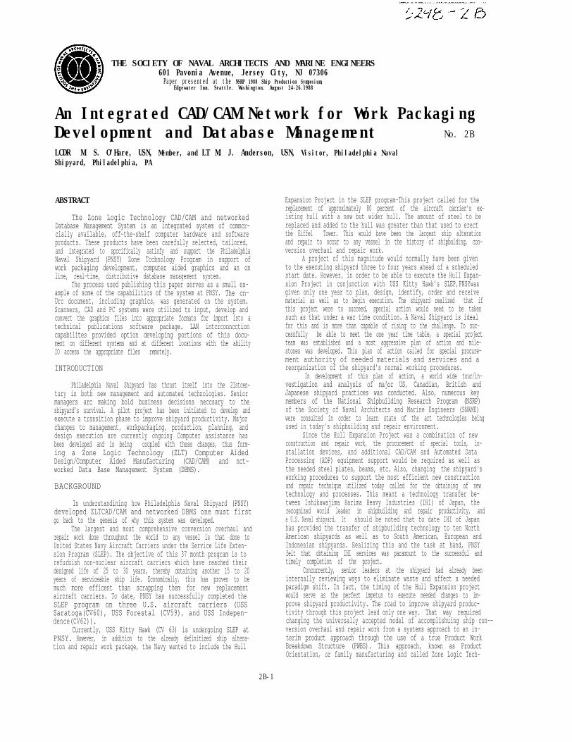
conversion, Interleaf, Unigraphics, Ventura, the industrial versionof Cadkey, Enable, WordPerfect, dBase III Plus, Palantir software,Novell TCP/lP, Lotus, DBGraphics, MathCAD, Chartmaster andan Engineering QA statistical package). These all serve severalsoftware functionalities such as Design, Manufacturing/Engineer-ing and Outfit Planning. They are all linked on a fiber optic(F.0.)ethernet backbone. The data flow between these systems is il-lustrated in Figurel2
Future plans call for the shipyard’s MIS terminals andnumerous independently operated PCs (i.e., SNAP/Wang) to belinked to the F.O .ethernet backbone. However, Wang does not cur-rently support ethernet This is an unfortunate situation not only forPNSY but also for the Navy as a whole The integration of Wangterminals to an ethernet backbone could save thousands of dollarsannually in the reduction of modems and twisted copper pair phonelines. The other potential benefits are too obvious to mention andit is hoped that the Navy can persuade Wang Systems to capitulateon this matter before long.
Input to the system is handled a number of ways, ranging fromthe scanning of data to the manual input of data. The system has anumber of conversion utilities that support file transfer to and fromall LANs on the system. This section illustrates paths available forthe transfer of data between LANs and output devices Figure 13,Data File Conversion/Transfer Paths, shows a number of pathsavailable utilizing conversion routines on each system. The pathsare numbered and a detailed explanation is provided below
1)ANA-tech Scanner Raster Files(Ird). Raster files area oneto one picture. ANA-tech supports a raster editor allowingsome clean up capabilities. ANA-tech also supports vectoriza-tion of these raster files and has a graphic editor for cleanup.
2) Palantir Scanner is a document scanner that allows thescanning of text/graphics. The file is broken into two seperatefiles editing is required. The graphics editing and text edit-ing are handled by seperate pieces of software. The Palantiralso supports conversion utilities allowing file transfer to othersoftware packages.
3) This box shows a typical document (Text/Graphics) that hasbeen scanned by the Palantir, converted and transferred intoVentura (technical publication package) and printed on the
Figure - 11 ZLT Operating Systems
2B-11
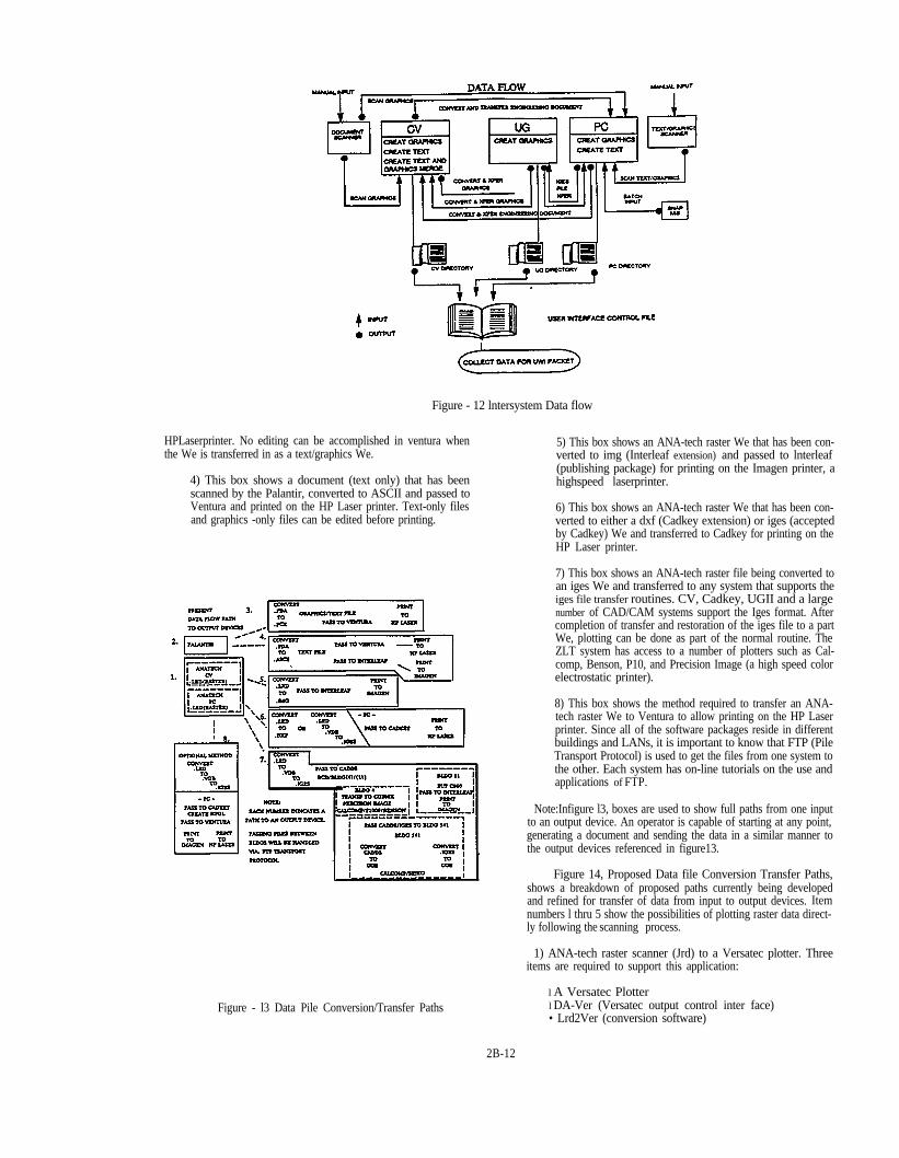
Figure - 12 lntersystem Data flow
HPLaserprinter. No editing can be accomplished in ventura whenthe We is transferred in as a text/graphics We.
4) This box shows a document (text only) that has beenscanned by the Palantir, converted to ASCII and passed toVentura and printed on the HP Laser printer. Text-only filesand graphics -only files can be edited before printing.
Figure - l3 Data Pile Conversion/Transfer Paths
5) This box shows an ANA-tech raster We that has been con-verted to img (Interleaf extension) and passed to lnterleaf(publishing package) for printing on the Imagen printer, ahighspeed laserprinter.
6) This box shows an ANA-tech raster We that has been con-verted to either a dxf (Cadkey extension) or iges (acceptedby Cadkey) We and transferred to Cadkey for printing on theHP Laser printer.
7) This box shows an ANA-tech raster file being converted toan iges We and transferred to any system that supports theiges file transfer routines. CV, Cadkey, UGII and a largenumber of CAD/CAM systems support the Iges format. Aftercompletion of transfer and restoration of the iges file to a partWe, plotting can be done as part of the normal routine. TheZLT system has access to a number of plotters such as Cal-comp, Benson, P10, and Precision Image (a high speed colorelectrostatic printer).
8) This box shows the method required to transfer an ANA-tech raster We to Ventura to allow printing on the HP Laserprinter. Since all of the software packages reside in differentbuildings and LANs, it is important to know that FTP (PileTransport Protocol) is used to get the files from one system tothe other. Each system has on-line tutorials on the use andapplications of FTP.
Note:Infigure l3, boxes are used to show full paths from one inputto an output device. An operator is capable of starting at any point,generating a document and sending the data in a similar manner tothe output devices referenced in figure13.
Figure 14, Proposed Data file Conversion Transfer Paths,shows a breakdown of proposed paths currently being developedand refined for transfer of data from input to output devices. Itemnumbers l thru 5 show the possibilities of plotting raster data direct-ly following the scanning process.
1) ANA-tech raster scanner (Jrd) to a Versatec plotter. Threeitems are required to support this application:
l A Versatec Plotterl DA-Ver (Versatec output control inter face)• Lrd2Ver (conversion software)
2B-12

Figure - 14 Proposed Data Conversion/Transfcr
These items allow a scanned document(Jrdraster)to be out-put directly to a Versatec plotter that is connected to the ANA-techscanner. Drawing replacement and reproduction is handled quick-ly utilizing this method.
FIBER OPTlCS NETWORK
A Fiber Optic (F.O.) Cable system has been installed at PNSYto link together building facilities for new and existing CAD/CAMand ADP equipment in support of ZLT. Sixteen (16) majorshipyard sites have been linked on a central active star Local AreaNetwork by approximately five (5) miles of F.O. cable.
One of the primary functions of this system will be to supportZLTCAD/CAM requirements. The system uses the ethernet IEEE802.3 networking protocol and provides ten million bits/secondbandwidth or greater (Le. maximum data transfer rate) capacity.The cable plant has been designed to satisfy ZLT requirements andto provide a backbone for shipyard data communication. Initially,electronics are being installed to support all ZLT locations.However, this state-of-the-art fiber optics system will support over1,500 transceiver cable ports. Also, with the use of terminal servers
and multi-post transceivers, over 200.000 ports/connections maybesupported.
The overall potential to iii every shipyard computer systemwithin the buildings indicated below, now and in the outyears, is pos-sible. Immediate access to the fiber optic backbone wig be a func-tion of each system’s ethernet capability or supporting protocolEvery shipyard computer system will be evaluated and appropriatesoftware and electronic hardware will be specified for futureprocurement and hook up to the system. In the long run, this willyield cost savings in the hundreds of thousands of dollars in thereduction of twisted copper pairs currently being used to transmitdata.
Numerous Wide Area Networks (WAN) linking the buildingfacilities will provide support to local file/data exchange and theresource sharing requirements that will aid cost effective manage-ment throughout the network. Transmission is provided via a F.O.cable and an Ethernet coaxial 50 ohm cable in the LANs. Specifica-tions for the 16 and 28 multimode F.O. system with capabilities oftransmitting 10,000,000 bits per second (BPS) are as follows:
l cable sheath with a PVC outer jacketl the center member is a Kevlar dielectric with reinforce-
ment for tensile strengthl F.O. core diameter: 62.5 microns +/- .003l F.O. core cladding diameter: 125 microns +/- .003l Numerical aperture: 0.29 microns
l Attenuation at 850 nm: 3.0 dB/km maxl Attenuation at 1300 nm: 1.0 dB/km min.
The Ethernet coaxial cable specifications are as follows:
Cable sheath with yellow PVC outer jacket ring-bandstripes at 2.5 meter intervals for transceiver tap-inCore: solid tinned copper .0855 rated at 1.42 Ohms permeter and 4.66 Ohms per kilometerShield: aluminum/polyester shield bonded to dielectric92% trimmed copper braid rated at 1.52 Ohms per meterand 5.0 Ohms per kilometer
The network links fifteen (15) buiIdings and four (4) trailersat one waterfront worksite in support of the Zone TechnologyProduction Group. Figure 15 provides a geographic overview of theshipyard and the networked buildings, while the following tablepresents the major functional responsibilities housed in the variousbuilding:
The network consists of links between the following buildingfacilities, building 1000 being the network hub:
Buildings linked #F.O.pairs Length of run
1000-121 16 1953'(595m)1000-22 16 3078'(938m)1000-11 28 3170'(966m)11-4 16 2124'(647m)11-7 16 705'(215m)11-3 16 1059'(323m)4-5 16 997'(304m)4-83 16 l901’ (579m)83-624 16 1636’ (499m)10-57 28 2852’ (869mm)57-990 16 1601’ (488m)57-620 16 3380(1030m)620-620ext 8 1690'(515m)
Figure 16 provides a systematic illustration of the overall F.0.network throughout the shipyard A description of this system isprovided in the following paragraphs.
The total F.O. cable system runs26,146’(495miles)or7,968m(7.97km). Building 1000, the Hub of the outside plant system,provides the location for the Central Active Star.
The Central Active star network design has established build-ing1000as the geographical hub linking facilities in the easterly andwesterly sectors of PNSY. The network has established aready-nowsystem and provisions to meet demands for future expansions. Theready-now system services the following facilities:
Buildings linked #F.0. pairs Length of run
1000-11 28 3170' (966m)11-4 16 2124'(647m)1000-57 28 2852'(869m)
2B-13

2B-14

Figure - 16 PNSY F.O. Network Schematic Overview

57-990 16 1601’ (488m)
The total Central Active Star F.O. cable system runs9,747'(l.8miles)/2,671m (3.0km). The PNSY demand for future expansionprovides an additional 16,399’ (3.1 miles)/4,998m (5.0km) of F.O.cable to link the following facilities to building 1000:
Building Linked #F.O. Pairs Length of Run
1000-121 16 1953’ (595m)1000-22 16 3078’ (938m)11-7 16 705' (215m)11-3 16 1059' (322m)4-5 16 997' (304m)4-83 16 1901’ (579m)83-624 16 1636’ (499m)57-620 16 3380(1030m)620-62Ocxt 8 1690 (515m)
Utilizing building 1000 as the network design hub providesF.O. cable expansion capabilities of 26,146’ (4.95 miles)/7969m(8.0km) that will ultimately link up and service sixteen (16) facilities.Already existing underground conduit provided a means wherebysingle ducts were used to accomodate several feeds into the build-ing facilities.
The system design minimized connectorization by utilizingpatch panel (pp) frames at designated building sites. The patchpanel sites provide optimum utilization of F.O. for a ConcentrationPoint (CP) in building 1000. The strategically located interconnec-tion patch panel sites gain the advantage of circuitry (F.O.) trafficcontrol management and diversification of full period F.O. perfor-mance.
The five PP interconnection sites interface a total of 72 F.O.pairs through the Central Active Star, with 80 F.O. pairs in reservefor future expansion. The elimination of F.O. field straight spliceshas provided a minimal attenuation loss. The F.O. cable wasdelivered at an average of 1.5 dB per km, providing a transmissionadvantage from the maximum specified 3.0 dB at 850 mmbandwidth.
STATUS AND CONTROL DATABASE MANAGEMENT SYSTEM
The Status and Control database is the heart of the Unit WorkInstruction (UWI) and Shop Work Instruction (SWI) automatedsystem This control system development was, by design, restrictedto the use of previously selected hardware and software elements ofthe Zone Logic computer subsystem. This decision required main-taining storage of data, graphics and text in its native form on theparticular subsystem through which the data was input or generated.The major drawback to this is restricted configuration and limiteddata update control by the originator. Multiple versions of a file canexist if manual control procedures are not employed. Improvementof this limitation is to be addressed in a future update utilizing theincorporation of a distributive. database concept, a concept which isvery much a state-of-the-art technique in database management
The Status and Control Database System is a multi-userdatabase application developed using dBase III Plus technology (togo to dBase lV when available) and running in a Novell PC networkenvironment. A discussion of the Global design information for thedatabase system, covering the module structure of the system,module independent design criteria and the software technologyused to implement the system is provided in the followingparagraphs.
The fundamental software development technology used toimplement the Status and Control Database System is dBase IIIPlus, a relational database system that incorporates a command lan-guage interpreter. It can be used to develop a database applicationrunning in either a single or multi-user environment Because it iseasier to develop code in an interpreted environment, the commandlanguage interpreter was used to do the initial source code develop-
ment. As modules were completed, initial testing was performedand necessary modifications were made.
In addition to traditional coding methods, a dBase IlI Plusprogram generator called the UI Programmer was used The UIProgrammer is a software tool that generates dBase III Plus sourcecode for menuing, data entry and report forms. The code genera-tion is based on source code templates provided by the program-mer.
A compiler called Quicksilver that supports the dBase III Pluscommand language was used to produce the production version ofthe database system. The compiled code has several advantagesover interpreted code in the production system, chief among thesebeing the speed of execution. While interpreted code is in essencecompiled every time it is executed, compiled code is only compiledonce. Compiled code is also more immune to changes by the usercommunity as the source code need not be kept on-line. This meansthat the syntax written by the programmer, once compiled, is the ob-ject code (machine language). Thus, the user can not make chan-ges arbitrarily. This restricts changes to that individual or set ofindividuals controlling the compiler set by keeping the program ofline and free from potential tampering. The RAM memory neededto execute compiled code is substantially less than that required toexecute identical interpreted code because the memory space takenup by the interpreter itself is not required.
AdBaseIII Plus application consists of two primary elements:data tables and code modules. The data is stored in the data tableswith the code modules providing an interface between the users andthe data that allows for easy data access while still protecting the in-tegrity of the data.
The Status and Control Database System consists of severalprimary data tables and a hierarchical set of code modules. Thesedata tables and code modules are grouped into the following func-tional subsystems:
l Job Order Production Control (JOPC) subsystem• UWIsubsystem• Library Component subsystem• Material subsystem
The subsystem boundaries are not strictly enforced. Codemodules from one subsystem may access data tables from a differentsubsystem and invoke additional code modules from yet anothersubsystem. None the less, the subsystem organization is a con-venient one to use when planning the development of the system.Figure 17, Data Table Subsystem, provides a pictorial repre-sentation of the data table subsystem. A description of each of thedata tables follows:
1)The master job order production Control(JOPC) List hasone record for each JOPC in the system. It contains the JOPCnumber (#), its current production status, pointers to a num-ber of subordinate databases and a number of related JOPCdata items, such as its title and the planner’s name.
2) The JOPC Shop Man-Hour List is subordinate to theMaster JOPC List. It contains one record for each shop/man-hour pair on the JOPC. Each record includes a JOPC #, ashop #, and a number of man hours
3)The JOPC/UWI Task Assignment List is subordinate toboth the Master JOPC List and the Master UWI List. It con-tains one record for each JOPC task defined in the system. Italso contains information that defines the task and specifieswhich UWI it was assigned to. It includes the JOPC #, theUWI# to which the task was assigned, a unique identificationnumber, the shop # and the number of man-hours being allo-cated and, if possible, a descriptive definition of the task. AJOPC is considered to consist of a number of tasks, each ofwhich must be assigned to a UWI before the JOPC can be con-sidered completely allocated
2B-16

Figure - 17 Data Table Subsystem
4) The JOPC Material List is subordinate to both the MasterJOPC List and the Master Material List. It lists the JOPC#,stock # and quantity of each item assigned to the JOPC.
5) The JOPC/UWI Material Assignment List is subordinateto the Master JOPC List, the Master UWI List and the MasterMaterial List. It contains the JOPC #, the UWI #, the itemstock # and the quantity assigned to a particular UWI.
6) The Master UWI List has one record for each UWI in thesystem- It contains the UWI #, its current production status,pointers to a number of subordinate databases and a numberof related UWI data items such as the preparer’s name.
7)The UWI Component List is subordinate to the MasterUWI List and the Master Component Text and Drawing List.It contains one record for each text or graphic component re-quired to complete a particular UWI and includes the UWI# and the unique component #.
8) The Master Component Teat and Drawing List containsone record for each scanned drawing or text component. Itcontains a unique identification number, the originalreference number for the text or drawing, descriptive infor-mation about the original reference material, and data con-cerning the scanning and on-line storage of the material.
9) The Master Material List contains one record for eachstock item reference listed in a JOPC material list- It containsinformation such as the stock #, name, description and es-timated cost of the item.
The Status and Control System is designed to be a ‘bul-letproof’ system- It should not be possible for the user to issue in-advertent commands that destroy or corrupt the data- The userinterfaces to the database system consist primarily of menus, dataentry forms and report forms- All of these interfaces are similar inappearance. With a single interface type, such as data entry forms,the design and appearanee of all instances of that interface type areidentical, with only minimal allowances made for the differing re-quirements of each situation- This was accomplished primarilythrough the use of the UI programmer’ software development tool.
In most cases, a data entry form performs three different userfunctions data entry, data modification and data review. In orderto allow for review without the possibility of inadvertent modifica-
tion, all functions that update the database must be confirmed bythe operator. All source code modules are formatted in a similarmanner. It is not possible, with only a quick look at the file, to deter-mine the programmer responsible for the code. Figure 18, CodeModule Hierarchy, provides a pictorial representation of the codemodule subsystems. A description of each of the code modules fol-lows
1) The Master Menu code module does not belong to any ofthe subsystems. It implements the initial user interface andprompts the user to select one of the subsystems (JOPC,UWI,Component or Material) and invokes that subsystem’s menumodule.
2) The JOPC Menu code module prompts the user to selectone of the JOPC functions and invokes the related codemodule.
3) The JOPC Definition and Data Entry module supportsentry and modification of the data from the JOPC form- Thisdata is used to create or modify records in the Master JOPCList and the JOPC Shop Man-Hour List
4) The JOPC/UWI Task Assignment module supports thedefinition and modification of JOPC tasks and their assign-ment to a UWI. A record is added to the JOPC/UWI Assign-ment List for each defined task. If the UWI to which the taskis assigned doesn’t already exist, a recode is added to theMaster UWI List and the user is prompted to enter the UWdefinition data (it calls the UWI Definition code module).
5) The JOPC Matcrial Definition module supports entry andmodification of data pertaining to the material allocated to aJOPC on its associated Job Material List (JML). One recordis added to the JOPC Material List for each item- If the itemis not already entered in the Master Material List, the user isprompted to enter the item definition data (it calls theMaterial Item Definition code module).
6) The JOPC/UWI Material Assignment module supports theassignment of a JOPC’s material allocation to its subordinateUWIs. A record is added to the JOPC/UWI Material Assign-ment List for each assigned item. If the UWI to which an itemis assigned doesn’t exist ,the user is prompt to enter the
2B-17

Figure - 18 Code Module Hierarchy
UWI definition data (the module calls the UWI Definition codemodule).
7) The JOPC Status Report Generation module generates areport listing all or some subset of the JOPCs in the system,This report can be generated in several formats- The shortformat shows only data that can be comfortably fit on an 80character line and emphasizes production status. Option willallow the the to include UWI assignments, material alloca-tions, UWI material assignments and, as a group, all the re-lated data-
8) The UWI subsystem code modules will initially be operatedwithout either the JOPC or Material modules. The Com-ponent modules will be present in the initial system-
9) The UWI Menu module prompts the user to select one ofthe JOPC functions and invokes the related code module.
10) The UWI Definition and Data Entry module supportsentry, modification and review of the UWI boilerplate dataand its publication status data- Records are added to theMaster UWI List- This module is also invoked by severalJOPC modules.
11) The UWI Component Definition module supports entry,modification and review of the list of teat and graphic com-ponents required to publish a UWI. A record is added to theUWI Component List for each component. If the componentis not already on-line., the user is prompted to enter com-ponent definition data (the module calls the ComponentDefinition code module).
l2) The UWI Component Transfer module supports thetransfer of on-line components from the system where they arestored to the local PC for further processing. This is ac-complished by programming the dBase III Plus code to issueFile Transfer Protocol (FTP) commands.
l3) The UWI Status Report Generation module generates areport listing all or some of the UWIs in the system- Thereport can be generated in several formats. The short formatwill display only the data that can be comfortably fit on an 80
character line and will focus on the publication status of the UWI.Optionally. the user can request that JOPC task assignments, JOPCmaterial assignments and/or related data be included in the report.
14) The Component Data Entry and Definition module supports entry, modification and review of the text and graphiccomponents available for inclusion in a UWI. One record isadded to the Master Component List for each component.This module can also be invoked by the UWI ComponentDefinition module.
15) The Component Status Report Generation modulegenerates reports listing all or some of the components in thesystem. The report can be generated in several formats.There are two short formats. Each will display only that datawhich can be comfortably fit on an 80 character line. One for-mat will address those components that need to be scannedwhile the other addresses those components that are alreadyon-line. The comprehensive format will display all stored datafor each component.
16)The Material Item Definition and Data entry module sup-ports the entry, modification or review of material item defini-tions. One record is added to the Master Material List foreach new item. This module is also called from the JOPCMaterial Definition module.
17)The Material Status Report Generation module generatesreports listing some or all of the material items in the system.
BENEFITS
while it is still too early to be able to provide detailed costsavings realized by the implementation of the ZLT CAD/CAM Net-worked DBMS, several instances of savings or benefits in design,planning and production man-hours have already been noted:
1) The scanner was utilized to help develop preplanned rout-ing and location diagrams for the placement of tank suctionand cleaning lines used to dean some 720 tanks onboard USSKitty Hawk- This, coupled with ZLT principles of planningand management, helped realize over a $2 million savings,with all tank cleaning work completing on schedule anddefinitely under budget.
2B-18

2) The Mold Loft has used the upgraded UGII CAD/CAMsystem on various projects such as in the development of draw-ings for mast work, foundation work and for a new bulbousbow for USS Kitty Hawk- All of these tasks were completedon schedule and budget due to the assistance of this newequipment. Mold I-oft personnel have found the UGIIupgraded system so efficient that it is manned constantly andused to replace manual methods as much as possible.
3) The design division has utilized the new CAD equipmentin developing a first for PNSY in a design for production workpackage of USS Kitty Hawk pump room number five (5).Original design effort amounted to 400 mandays. After be-coming familiar with the new sytem, time requirements for thenext pump room will be reduced by half and will be ahead ofscheduled completion by one month.
4) Utilization of the new peripheral electrostatic color plotterallows for the printing of colored drawings in only ten (10)minutes. Compared with the previous norm of two (2) hoursper color pen-plotted drawing this is proving to be a majorsavings not only in the production of multiple copies of multi-colored damage control plates, but also in the drawing of 2-Dand 3-D configuration overlays.
5) Regarding the utilization of the numerous PCs, continualusage of the PCs has proven to be a necessity to handle thevolumes of data to be sorted and distributed on a real-timebasis in support of the shipyard’s ZLT efforts.
6) The scanners are used daily to input drawings to the GADsystem for supporting production work and allowing forclearer understanding and definition of work to be performed.
7) Total development of UWIs is not fully automated at thistime, but at full implementation it is expected to significantlyreduce the time/cost to develop UWIs.
In all, these illustrate only a few isolated eases of the benefitsbeing realated from the installation of the ZLT CAD/CAM Net-worked DBMS.
SUMMARY
As is evident, many innovations have been implemented atPNSY in a relatively short interval- Major changes to management,work packaging, production, planning and design are infull swing insupport of the ZLT efforts being applied to thirty (30) percent ofUSS Kitty Hawk’s SLEP. The project is progressing well with allplanned targets being met and the ZLT CAD/CAM and NetworkedDBMS scheduled to be completed by fall of 1988. Plans are alsobeing worked to increase PNSY ZLT efforts on future ship over-hauls.
The accomplishment of this much in such a short time can bemainly attributed to four (4) key factors. First, a “war time’ condi-
tion was initially enacted to ensure the success of the Hull Expan-Sion Project. Thus, eventhough the project was eventually cancelledsome thirteen (13) months later, it would have been too costly toretreat, let alone stop what had already been put in motion. Second,senior shipyard management are behind the project and have given ittheir full support; it cannot be stressed enough how critical this hasbeen to the success of the project thus far. Third a project Officewas established to direct and manage all ZLT related matters-Fourth, an SI was used and has performed extremely well and beenan irreplaceable asset to the program.
The basic approach in developing this project has been tomaximize technology transfers with IHI and other sources whereverpossible. investigations of industrial and manufacturing facilitieshave proven invaluable, as has heavy involvment by PNSY with theNational Ship Building Research Program (NSRP). The ZLTProject Office's philosophy has been one of “going out and kickingthe tires, getting smart quick, analyzing the data, making thedecisions that they are being paid to make, and following throughon the execution of the game plan.” Naval Shipyards must quicklybecome more competitive; buying “futures’ or getting heavily in-volved in development efforts while needs go unfulfilled will onlywork to the detriment of shipyards.
With the rate at which the computer industry is moving, it iscertainly realised that by the time computer hardware and softwareis received and installed, it is already obsolete. Or is it? The dozensof computer periodicals available (which basically sell futures) seemto always have computer managers looking for that one R2-D2 donethat will solve. all of one's problems in one clean sweep. Is it actual-ly realistic to study periodicals and make plans based on just whatone reads? Or is it more objective to actually perform real-time tech-nical evaluations? These authors vote for the latter.seen and understood, there is no turning back
Once you have
A perfect example of this is the instalation of PNSY’s F.O.LAN. Initially, shipyard personnel managers were sceptic, basically out of lack of knowledge of fiber optics. Once the SI brought inhighly qualified fiber optic engineers and technicians, shipyard fearsand doubts were put to rest. In fact., it took only six weeks to installthis system. If that isn’t an example of ”kicking the tires, getting smartquickly and making a sound technical and business decision” thatfiber optic technology today is good enough to go with. then theauthors are not sure what is. The decision to go with 32.bit micro-computers operating on MS-DOS vice going to OS-2 is another ex-ample of going with what the market has proven as a winner to dateAlso, by following the lead of private industry and the SI, the acquisi-tion of scanner technology has been made a reality at PNSY.
Regarding the use of an SI, as stated earlier, if managedproperly and if true professional lines of communication are estab-lished and maintained, it is hard for the authors to see how anythingshort of success can occur.
Throughout this project, Cost, Schedule and Control (CS2)procedures were used as one of the major tools to monitor andprogress the SI. To this end, the maintaining of schedule and budgethas been a reality.
2B-19

Additional copies of this report can be obtained from theNational Shipbuilding Research and Documentation Center:
http://www.nsnet.com/docctr/
Documentation CenterThe University of MichiganTransportation Research InstituteMarine Systems Division2901 Baxter RoadAnn Arbor, MI 48109-2150
Phone: 734-763-2465Fax: 734-763-4862E-mail: [email protected]