The MSB Journal - November 2007
42
Volume I Issue IX -Ship Modeling Forum Online Modeling Competition - The Matthew Project - Shaping the Hull - Constructing and Operating a Ropewalk for Model Ship Builders
-
Upload
msb-journal -
Category
Documents
-
view
225 -
download
3
description
Online Journal for scale model ship builders. Official publication of www.modelshipbuilder.com
Transcript of The MSB Journal - November 2007

Volume I Issue IX
-Ship Modeling Forum Online Modeling Competition- The Matthew Project - Shaping the Hull- Constructing and Operating a Ropewalk for
Model Ship Builders

Volume I Issue IX
www.modelshipbuilder.com
2
The MSB JournalISSN 1913-6943
Volume I, Issue IX
November 2007
© www.modelshipbuilder.com
All articles published in The MSB Journalare covered under international copyright laws.
This newsletter may be re-distributed freely as long as it remainswhole, intact and un-altered. We also urge you to print a copy
for your workshop or reading area. No portion may be reproduced in any form other than as stated without express written consent.
Published bywww.modelshipbuilder.com
Front CoverPhoto
Ship Modeling Forum Competition
How to Contact The MSB Journal
By email: [email protected]
By Snail-MailModelShipBuilder.comc/o Winston Scoville
5 St. Charles Place RR 5Clinton, Ontario, N0M 1L0
Canada

Volume I Issue IX
www.modelshipbuilder.com
3
Contents
Editor’s Notes - 4
Constructing and Operating a Ropewalkfor Model Builders - 5
Ship Replicas - 14
Ship Modeling Forum Online Modeling Competition - 15
From The Files of ShipWreckCentral - 19
The Matthew Project - Shaping the Hull - 20
Building the Bluenose IV - 29
Grog - 33
Ships From The Past - 35
Contributor’s Pictures - 36
What Ship is This? - 40
Crossword - 41

Volume I Issue IX
www.modelshipbuilder.com
4
Editor’s Notes
Another month has come and gone and here weare again!
This issue we’re going to try adding an onlineHTML version of the MSB Journal. The contentwill be the same, but as you will see if you visitthe website, the layout will be quite different.
We also have a new addition to The MSB Journal.Modeler Mike Brown has graciously taken on anongoing project to follow the building of theschooner Bluenose IV. This will be a rareopportunity for us to follow the build of an actual
schooner from the planning stages right through to it’s completion. If there are any questionsthat you may have about this build as we go along be sure to let us know. We are in directcontact with the organizers of the project and as well Mike is in direct contact the shipyard thatis building the schooner so we should be able to get you answers direct from the source. I’msure I speak for all the readers when I say “Welcome aboard Mike!!!!”.
As always, I again would like to remind you that we are always looking for content for upcomingissues of The MSB Journal. Content can be anything from picture submissions, to short articles,tips and techniques, jigs and things that make some processes easier, to full blown articles.Maybe you’d like to take on a monthly column on some modeling subject (rigging, planking, POF,POB etc...). We’d like to hear from anyone who’s interested. Don’t be shy, drop us a line.
Okay, this month I’ll keep things real short!
Happy Modeling!
Winston Scovillewww.modelshipbuilder.com

Volume I Issue IX
www.modelshipbuilder.com
5
Constructing and OConstructing and OConstructing and OConstructing and OConstructing and Oppppperating a Roperating a Roperating a Roperating a Roperating a Ropewalkewalkewalkewalkewalkfor Model Sfor Model Sfor Model Sfor Model Sfor Model Ship Buildership Buildership Buildership Buildership Builders
by Eugene Larson
The ropewalk, with a very short setup to fit the photo. The drive motor isoptional as discussed in the text. The drive end is to the right, the idler end is
at the left, the top is mounted on the strands, and the bucket provides tensionas the rope is laid up. There are four threads to each strand for this photo.
The term ‘ropewalk’ drives a horrible fear into many ship model builders, and it becomes almost amatter of avoiding the subject at all cost. However, for very small “cost” and a little effort youcan make your own ropewalk. With only a few minutes of further time you can learn to use itproductively.
Rope made on the ropewalk. Far left isthe basic unidentified polyester thread.Next is a three-thread right-hand rope.Middle is a six-thread, two-thread perstrand rope. Next is a twelve-thread,four-thread per strand rope. Far right isa twelve-thread, four-thread per strandleft-hand rope of #18 button & carpetcotton thread.

Volume I Issue IX
www.modelshipbuilder.com
6
I have made several, and always tried mounting an electric motor to drive them. This really isnot necessary, as I discovered when I saw Cor Hardonk, Curator of ship models at the PrinsHendrik Maritime Museum in Rotterdam, demonstrate his simple machine during the NRG's maritimetour of Northern Europe in 1996. He spun a beautifully laid rope in just a couple of minutes byhand cranking. The hand cranking method is satisfactory for shorter length of rope, in the rangeof three to six feet. For ropes longer than six feet there are definite advantages to the motordriven ropewalk, the main one being the ability to be at the point of lay-up of the rope.
When the perceptive eyes of the Nautical Research Guild's reviewers doing the Model ReviewService and Model Judging Service on my tug caught the deception of a last minute inclusion ofpackage twine for a tow rope to meet a display deadline, I decided to construct the simpleropewalk seen in Rotterdam to lay-up the planned rope.
The first requirement in describing a ropewalk is to understand the construction of the rope. Anexcellent pamphlet produced by The Historic Dockyard, Chatham, called The Ropery, goesthrough the entire process in sixteen pages. The pamphlet may still be available. Essentially, arope (or line) is made up of strands that may vary in number for various purposes, but for amodel ropewalk we will stay with three. These strands are made up of yarns, which can varyfrom one to perhaps twenty. The yarns are made up of the raw material such as hemp fiber. Fora model ropewalk there will only be rope, strands and yarns, and the yarns we will use arethreads of linen, cotton, or polyester.
The Anatomy of Rope
A. FibresB. YarnsC. StrandD. Rope
Photo courtesy of The HistoricDockyard, Chatham.
Types of Rope
a. Four-strand, or shroud-laid, with a'goke' or heart made from thinner rope.
b. Three-strand, or hawser-laidc. Nine-strand, or cable-laid
Photo courtesy of The Historic Dockyard,Chatham.
ab
c

Volume I Issue IX
www.modelshipbuilder.com
7
The yarns are twisted together in such a manner that they lay up ("close" is the English term)into a rope and in doing so neutralize the twisting. The finished rope is neutral with no tendencyto twist further or to unravel, except for fraying at the ends, which is corrected by serving therope. This fraying is natural and will happen in any rope you purchase.
The photos and drawing show the basics of the design of the ropewalk. It consists of a right ordriving end, a left or idler/moveable end, a top or guide to obtain an even lay, and a weighthanging off the left end to provide tension. The essential materials are scrap woods, one largegear, three small gears, brass rod and tubing, a sheet of metal, and a wood dowel. The gears areobtained at a hobby shop that has a good supply of R/C cars. The larger one is a plastic 66tooth, 32 pitch, two-inch (approx.) gear by Traxxas, #3166 ($3.00). The three smaller gears aremetal - 20 tooth, 32 pitch, with a 5/8-inch diameter (approx.) by RRP, #0200 ($2.95 each). Theimportant things to remember are that there should be a large difference in the diameters, andthe pitch (teeth per inch) should be the same. A few additional items are necessary if theropewalk is to be powered.
For reference purposes thedimensions of this unit areapproximately 10 inches by fiveinches for the full base, and teninches high. The wood is 7/8 inchesthick.
Obtain brass rod to fit the center holes of the gears. The gears are mounted on the brass rod.The smaller gears conveniently have set screws to hold them. A large gear with setscrews couldnot be found, so a mounting plate had to be fabricated to hold the gear to the rod. This can beseen in the photo. I have since found that a good epoxy will hold the large gear on the shaft ifthe surfaces are clean and abraded. It can also be seen that I substituted tubing for the rod onthe larger gear. For the two sizes of rods locate brass tubing that is the next size larger so therod fits snugly in the tubing, but does not bind. The tubing will become the sleeves or bearings inwhich the rods holding the gears run.
The wood supports should be at least 3/4 inch thick, and be hardwood, not pine. I used mapleso the bearings would not work loose in the wood. A groove (dado) was cut in the wood basesfor the upright pieces. Later the uprights were glued and screwed to the base. The dadoprobably is not necessary if you do not have the capability. But first, mark the right upright withthe location of the center of the large gear. This should be near the top to give clearance for

Volume I Issue IX
www.modelshipbuilder.com
8
the handle or motor. Place the large gear exactly on this center pencil mark, and put a small gearnext to it, ensuring a tight fit. Mark the center of the small gear on the wood. With a compassdraw a circle around the center for the large gear using the point for the center of the smallgear as a reference, but adding about 3/64 inch to the radius. This additional space will permitfree turning of the gears and hopefully will compensate for any errors in drilling the wood. (If thisfails, start with another piece of wood.) The small gears should be equally spaced around thelarge gear. Conveniently, the radius of any circle can be ticked off around the circumference andthe result is six evenly spaced marks. Use three of the marks to locate the holes for the bearingsof the small gears.
Drill the holes for the bearings. The small gears have a 1/8-inch drive rod. The outside diameterof the bearing tubing is therefore 5/32 inch. Use that size drill and do not attempt to enlarge thehole. Cut three bearings just slightly less than the thickness of the wood. Carefully drive thebearings into the holes using a rubber mallet or at least a protection on the end of the tube toprevent damage. If your tubing and drills are the same size as mine, the tubing should fit in thehole very snugly, and will not come out. If loose, I'm sure some epoxy will hold them in. Do thesame for the large gear bearing.
The rods for the small gears are cut so about an inch protrudes out one side and 1/4 inch on theother. Brass hooks are soldered into the end of the rods to hold the threads. The small gears ontheir shafts are mounted in the bearings as shown. On the power side there is a washer and acollar with a set screw. These collars are for R/C control rods and are available in the hobbyshop.
The large center gear mounts in a similar fashion, but a little innovation is necessary to hold it inplace since there are no control rod clamps with the large diameter required. An extra piece oftubing on the handle side, soldered to the handle mounting plate, works to hold the handle inplace with a small bolt and nut. Judicious use of epoxy on the gear center hole and on the largebrass tube will avoid using the mounting plate and soldering. Mount a handle, such as a wooddowel, loosely on the handle mounting plate, and the business end (right) of the ropewalk isfinished.
W. Kelley Hannan, National Research Guild member and shop notes coordinator, suggests thefollowing alternative method for locating and drilling the holes for the gears:
“For the rope walk you will have one large gear and three small gears mounted on aplate (or between plates) around the large gear. The large gear is turned by the crankor motor and drives the small gears.Drill a hole in the in the plate for the shaft of the large gear. Insert that shaft in the holeand slide the large gear onto it. Place the plate with gear on the table of the drill press.Position a small gear on the plate approximately meshed with the large gear. Chuck theshaft (or a piece of shaft material) for the small gear in the drill chuck. Now lower thedrill chuck and manipulate the plate so that the shaft for the small gear enters the holein the small gear. Lock or hold the drill spindle while you manipulate the plate to achievethe desired mesh. (Some backlash is not a problem with rope-walks. It is better than abinding mesh.) When the mesh is OK, clamp the plate to the drill press table.
Raise the spindle. Remove the small gear and its shaft. Put the appropriate drill in thechuck and drill the hole for the small gear shaft. Repeat for the other two gears in theirlocations.”

Volume I Issue IX
www.modelshipbuilder.com
9
The left end of the ropewalk has a rod with a hook on one end and a handle on the other,mounted in a similar fashion in a bushing so it turns freely. This follows the design of theRotterdam ropewalk, however I have found that for longer ropes it is more convenient to havethe left end turn freely. This is accomplished by placing a thrust bearing for model race cars onthe rod opposite the rope hook. Note, some use fishing swivels to provide free rotation. (Seelater note on the problems with the thrust bearing and swivel.) An additional item is an eye orhook on the base of the left end for tying a rope to a weight over the side of the table.
The final item required is the top, bobbin, cone or separator. I prefer the term top. The purposeof the top is to keep the strands separated until there is enough twist to start the rope lay upprocess or closing, and to make the strands come together evenly. The top is made from a pieceof hard wood. I used some dogwood that had been curing in my shop for several years. Make itinto the shape of an elliptical cone and cut or file three longitudinal grooves equally spacedaround the circumference. The exact shape is not critical but the grooves should be filed andsanded smooth and coated with varnish and wax.
The top in position.
This top is:1 3/4 inches long1 1/8 inches in diameter.These dimensions are not critical.
Note thrust bearing on the left.
To practice with the ropewalk, clamp both wood bases to a table about five feet apart. Placethree or four pieces of common thread ("yarn") on one of the three small gear ends. This threadgoes to the single rod on the left end. There should be some tension in the threads, and thetension should be about equal between the strands. Do the same for the other two small gearends. Place some weight in a bucket tied to a rope attached to the left end. Place the topbetween the three sets of threads. The tension provided by the weight should keep the top inplace. Remove the clamp from the left end and start turning the handle on the right end.Practice will give you experience with the amount of twist required and amount of weight, butinitially there should be quite a few turns taken.
As you turn the left end will try to move toward the right end since the rope is shortening due tothe twisting of the yarns. Let the movement occur, but do not let the rope go slack - be surethere is enough weight holding it back. However, too much weight (tension) will break thethreads. If not enough tension is exerted on the strands they will "bunch up" as they aretwisted. If this happens, do not throw away the lay-up. Just reverse the twisting until thestrands are back to normal, apply more tension, and then continue. When you think you haveenough twist, turn the left handle so the strands lay up into a rope. If the strands are given aleft-hand twist the rope will lay up right-handed. As the rope lays up the length will again vary,so be sure to keep tension, and control the top by hand as it moves along the rope so an eventwist is achieved. Do not let the top move freely as is done in some ropewalks that use model

Volume I Issue IX
www.modelshipbuilder.com
10
railroad tracks and wheels to permit the free movement. The top performs the critical lay-up,and it must have very positive control. Also as the rope lays up it is necessary to provide moretwist at the right in the individual strands. When finished the laid-up rope will be as much as onequarter shorter than the original length. Neutralize the rope by applying tension and relieving itwhile also rubbing your fingers along the rope. The rope should be close to neutral, but theremight be a little untwisting when it is removed from the ropewalk due to too much twist in thestrands relative to the turns in the laid -up rope. It is best to tie off the ends with a piece ofthread or a knot to prevent unraveling of the threads.
Right-hand or "hawser" rope, like the threads on a standard screw, and left-hand laid rope caneasily be done with multi-strand threads. In actual practice the right-hand rope is usually threestrands and the left-hand rope is nine strands, made up of three right-hand three strandedropes. A three strand left-hand laid rope is adequate for the small scales involved. With thisropewalk design turning the handle (large gear) in the counterclockwise direction produces right-hand laid rope. If one thread per strand is used care must be taken to ensure the direction oftwist does not unravel the thread. Some threads can be "untwisted" while others will fall apart.Most thread has a right-hand twist, therefore the lay-up of right-hand rope requires the singlethreads to be twisted in a left-hand direction. This takes the original twist out of the thread,and then twists it backwards. The result is a rope that is not as smooth as it would be if laid-upleft-handed. When more than one thread per strand is used, the threads twist upon themselves,and the original twist is not affected.
The rope walk with the motormounted. The control box andbattery holder allow the manufactureof any length of rope.
The addition of a motor drive permits the making of an unlimited length of rope because theoperator does not have to have easy access to the right, drive end. The motor I show is an oldsix-volt Dumas Pittman model boat motor with drive gears the same as those used for theropewalk. Mounting is straight forward, and the energy comes from D cells connected in series/parallel to provide three volts, and sufficient current capacity to make a lot of rope. Control isprovided by a wire wound potentiometer and a reversing switch (double pole-double throw,center off) mounted in a utility box, all available from a local electronics store (Radio Shack).Two short extension cords were cut in half and the cut ends were soldered to the components.The plug and receptacle ends attach to two appropriate length extension cords. The electricalarrangement with the on-off-reversing switch in the box requires four wires, two from thebattery and two to the motor. The batteries could be attached to the box to eliminate oneextension cord, but the added weight is not recommended. The box can be carried to the length

Volume I Issue IX
www.modelshipbuilder.com
11
of the extension cords to permit access to the controls while you are monitoring the action ofthe top and the lay-up of the rope. Turn on the motor and let the action begin. Be aware,however, the bucket with the weight may have to be moved as the rope is formed because itmay come all the way up to the top of the table. For a fifty-foot starting setup, ten feet couldbe lost in the forming of the rope, and this is the equivalent distance the bucket must travelupward.
Drive end detail with themotor mounted.
Wiring diagram for the electric drive motor. This permits access to the
controls while monitoring the action of the top and the lay-up of the rope.

Volume I Issue IX
www.modelshipbuilder.com
12
Following extensive use of the ropewalk inpreparing for a demonstration at the NauticalResearch Guild Conference in San Diego inNovember 1999, I have found a couple ofmodifications desirable. One of these modi-fications, as suggested above, is a motor atthe "far or single spindle end" of the ropewalk.This really helps in laying up the rope. I couldnot find a thrust bearing capable of freelyspinning while under the required tension toperform the lay up. (see photo)
A separate speed control was added to the"black box" for this motor so the rpm couldbe adjusted to coincide with the twisting.
Another improvement is the simple additionof a small rubber band on the top to hold iton the threads while preparing the setup,and in case momentary hand release isnecessary during operation. While laying upthe rope the top should be held to controlthe progress of the lay up. When about fourinches from the three spindle end (almostfinished with the lay up) remove the rubberband. At this time the top can also be re-moved and the final few inches can becontrolled by hand turning the gears andapplying proper tension on the rope. Afterabout five "tries" the proper feel for theentire procedure will be achieved. (see photo)
The final item (as shown in the top photo) is the device used to measure the diameter ofthreads as given in the tables below. This device was constructed by Ken Dorr, former NRGAdvertising and Books Manager. It is a dowel around which the thread is wound. Windsufficient turns to reach 0.1, 0.2, 1/4, 1/2 or more inches. Count the number of turns andthen divide by the distance. This is a much more accurate method of measuring thread
diameter than using a micrometer, which will crush the thread and give a distorted reading.
You are not restricted to this design or these materials. I have made a test ropewalk from Legopieces. The toy construction pieces include various size gears that can be purchased separately.The gears do not have the smooth contact like the R/C car gears, but that is not critical. Thecost of the r/c gears is really not significant.
The thing that frightens model builders most about ropewalks at first glance is that there are noset rules for the operation. It would seem that the size of thread, the number of strands, andthe amount of twisting related to the finished rope size could all be laid out nicely on a

Volume I Issue IX
www.modelshipbuilder.com
13
mathematics table. This is not possible due to the many variables involved. While watching the1,135 foot-long ropewalk at Chatham Dockyard in England I asked an operator if such a tableexists. He told me no, they lay the rope based upon experience. That ropewalk has beenoperating for over one hundred years. After practicing with various thicknesses of thread andvarious numbers of threads per strand, and after gaining experience with the amount of twistrequired, you can create and record a set of data for using the ropewalk.
You are now ready to use good material such as linen to lay up the required rope for a model.The model rope laid up on a ropewalk will have an appearance similar to the full-scale rope, andwill be much better than large diameter single thread material available in sewing shops. Even theold, out-of-production and highly coveted Cuttyhunk fishing line does not have a nice laid upappearance to it. Most of what I have from several years ago looks squashed and flattened. Onecaution should be noted. The number of turns in the rope is about half of the full-scalecounterpart. In other words, if the full-scale rope has 14 strands per foot, the model rope mighthave only seven per scale foot. This difference is not noticeable, and is far outweighed by thebetter appearance. However, when doing splicing, such as an eye splice with this model rope, athree tuck splice will be about twice as long as its counterpart in the full scale rope. This willlook odd, and the correction for the scale rope is to take fewer tucks.
The coveted linen line is difficult to find. It is sold in bulk to linen mills, but small bobbins areusually not available. As a decent substitute the polyester, poly/cotton, and some cotton will do,but granted, linen is the best if it can be found in the thinner diameters.
For a detailed discussion on the availability and characteristics of various materials on themarket suitable for rigging and for use on a ropewalk see the article “Rigging Material for ShipModel Builder” in the the last issue of The MSB Journal.
The Lumberyard for Model Shipwrights
We are proud to be your supplier of rough lumber,milled sheets and strips, plank on frame hull kits
and model ship kits.
Visit us today!www.dlumberyard.com

Volume I Issue IX
www.modelshipbuilder.com
14
Ship Replicas
Eastindianman Amsterdam
The original Amsterdam sailed up the North Sea in1749. In a raging storm the rudder snapped.The master decided to beach the brand-new shipon the south coast of England. Thus hehoped to save the people on board, the cargo andthe vessel.
But the East Indiaman soon sank into the mud,never to be freed again. The wreck has providedarchaeologists with valuable information about theconstruction of VOC ships, their cargoes andlife on board.
To learn more:http://www.scheepvaartmuseum.nl
H.M.S. Bee
H.M.S. Bee is a full-scale replica of her namesakeand has also received an historic warrantreinstating her as an honourary British Navy ship.At 79' H.M.S. Bee is representative of one of theoriginal supply schooners (Bee, Mosquito, andWasp) that were stationed at the PenetanguisheneNaval Establishment from 1817 to 1831.
Know of a Replica? Let us know and we’ll post it [email protected]

Volume I Issue IX
www.modelshipbuilder.com
15
The Ship Modeling ForumOnline Modeling Competition - Winners Circle
Well, the first Online Modeling Competition at the Ship Modelers Forum is finally over, the votesare in and the winners have been announced. Here they are:
Scratch & Semi Scratch
1st Place
USS Zellers DD-777Model Shipwright: Navarone
Scratch & Semi Scratch
2nd Place
Benj. F. PackardModel Shipwright: rjcote76248
Scratch & Semi Scratch
2rd Place
HMS Queen ElizabethModel Shipwright: grandad

Volume I Issue IX
www.modelshipbuilder.com
16
Modified Kit & Kit
1st Place
AgamemnonModel Shipwright: grandad
Modified Kit & Kit
2nd Place
HMAV BountyModel Shipwright: dhartwick
Modified Kit & Kit
3rd Place
Sovereign of the SeasModel Shipwright: Ronen

Volume I Issue IX
www.modelshipbuilder.com
17
Small Boat
1st Place
EV A KModel Shipwright: southpolecat
Small Boat
2nd Place
StellaModel Shipwright: markos
Small Boat
3rd Place
Edith F. ToddModel Shipwright: rjcote76248

Volume I Issue IX
www.modelshipbuilder.com
18
Honorable Mention
MusquidobitModel Shipwright: poppatom1948
Best in Competition
Whaleboat IIModel Shipwright: brian m
To view much better pictures of all these great models go to:
www.shipmodeling.net
Great Job Everyone!
A special thanks to John Guerin, Capt. of the Ship Modeling Forum and his assistants who helpedhim out with putting on the competition. I'm sure I speak for all of us when I say, "Job well done"
and we look forward to the next competition.

Volume I Issue IX
www.modelshipbuilder.com
19
From The Files of ShipWreck Central
HMS Hood, the ‘Mighty Hood’ asshe was popularly known in theRoyal Navy, was the largest warshipin the world on commissioning in1920 and a symbol of imperialstrength throughout the inter-waryears. Her sinking in one of the mostfamous naval engagements in history,against the German battleshipBismarck, has etched itself onBritain’s popular memory.
16–21 May: Based on reports thatBismarck was likely to attempt abreakout into the Atlantic, the shipwas more-or-less on alert. Strategieswere planned and discussed.
22–24 May: At sea with thebattleship Prince of Wales, anddestroyers Acates, Antelope, Anthony, Echo, Electra and Icarus. The force proceeded to watersoff southern Iceland in case Bismarck and the accompanying cruiser Prinz Eugen attempted abreakout into the Atlantic in that vicinity.
23 May: Bismarck and Prinz Eugen sighted byH.M.S. Suffolk in Denmark Strait.
24 May: Hood sunk in the Battle of the DenmarkStrait. In the engagement, Hood, Prince of Walesand Bismarck all received damage. At 0600, Hoodsank following a catastrophic conflagration/explosionresulting from a deep penetrating hit from Bismarck.Out of a crew of 1,418 only three (Ordinary SignalmanTed Briggs, Midshipman William Dundas and AbleSeaman Robert Tilburn) survived. Despite the lossof Hood, the action DID achieve the result of effectively cancelling the German sortie: ThoughPrinz Eugen escaped, Bismarck was later defeated and sunk with a heavy loss of life. No convoyswere lost to either ship.
H.M.S. Hood sank at 0600 hours, 24 May 1941, whilst engaged in battle against the Germanwarships Bismarck and Prinz Eugen. All but 3 of her complement of 1,418 crewmen went downwith the ship. It was the single worst Royal Navy ship loss of the Second World War.
Learn more about the ships listed in this article atwww.shipwreckcentral.com
Be sure to check out their interactive Ship Wreck Map
H.M.S. Hood
Wreck Site

Volume I Issue IX
www.modelshipbuilder.com
20
The Matthew Project
The Matthew Project is moving right along.In this issue we carry on the build with theshaping of the Hull.
I was hoping that by this issue we’d be ableto provide you with more information on howyou could get involved in the project.
Unfortunatley we’re not quite to that pointyet. There are still some things that have tobe worked out. The bottom line is, we justdon’t have all the answers we need yet toprovide you more information.
I can let you know the following though.When we are ready, there will be a fewoptions open to you if you wish to build this model. First, will be a kit which contains all thecomponents you need to build a Plank on Bulkhead model as we are building here. We have nottotally completed our model yet, thus the hold up in being able to provide you more info on thisat this point. It’s getting close, but there’s still a little ways to go.
Next we will be making available a set of detailed plans to allow you to also build this model butbased on materials of your choice. Often times modelers have their preferences when it comesto woods, blocks etc, so we have kept that in mind. These plans will not be available until themodel is completed. As was mentioned in the last issue, this model is being built based on variousfactors; the plans of the replica, the actual build of the replica and historical data available asscarce as it is. So, once they are ready, we’ll let you know.
I have been working hard, when ever I can find the time, in learning the ins and outs of somediscussion forum software. This will be a private members only area where modelers who areinvolved in the project can come, share ideas, ask questions, access updates, etc.....
Well that’s about all I can think of to mention on our updates for The Matthew Project thismonth.
Be sure to stay tuned in the next issue of the Journal for more information.
Now, on to the next installment of The Matthew Project.......

Volume I Issue IX
www.modelshipbuilder.com
21
The Matthew Project - Stage 2
Shaping The Hull
Shaping the hull can be done byhand with a block and sandpaper,however the job is much easier if asanding disk is used on a Dremel tool.A 60 grit disk will take down the hullquite fast. Shaping the hull beginsalong the sheer line where the fillerblocks are sanded down to thebulkheads. This will create a smoothbelt along the hull from bow to stern.The one major concern is the toptimbers at the deck line. You do notwant to sand the top timbers at thislocation too thin. Sand a belt about¾ to 1 inch wide along the blocksmaking sure you leave enoughmaterial on the top timbers.

Volume I Issue IX
www.modelshipbuilder.com
22
Once you have a smooth belt runningalong the hull at the deck level, the nextarea is along the bottom of the hull. Hereyou will be sanding in a rabbet. As youcan see in the photo the bulkheadsextend to the bottom of the centerprofile piece. Using a sanding disk withthe sandpaper extending beyond theedge creates a tool that acts like a sawand enables you to get right against theside of the profile piece. Sand down thebulkheads until they are about 1/16 belowthe edge of the profile piece. At the bowthe bulkheads are sanded down to matchthe curve of the stem.

Volume I Issue IX
www.modelshipbuilder.com
23
Overall shaping of the hull is done with a 60grit sanding disk. The key here is to use adisk that will span 2 bulkheads. The actualsanding is done between the bulkheads soyou touch 2 bulkheads, the back of theforward bulkhead guides the forward edge ofthe bulkhead next to it. Using the laser charas a guild you can sand an even forwardedge along each bulkhead as you work yourway to midship. Looking at the laser charnotice I am staying below the deck line andabout the bottom of the blocks and notsanding the top timbers, this comes later inthe final hull shaping.
A second tool is a home made sanding sledmade from a scrap piece of wood. The endsare rounded so the sled glides over theedges of the bulkheads rather than crashinginto them. By using an 80 grit sandpaperfastened to the sled with two-sided maskingtape you can begin to give the hull its finalshape.
Shaping the hull will be a dusty job and notsomething you can do on the couch whilewatching TV. As a matter of fact, anextension cord with a Dremel tool outside isyour best bet. As you sand and shape thehull what you are looking for is an even linebetween the bulkheads as you view the hullfrom the bow and stern. In many caseswhere the hull is built from only a fewbulkheads spaced far apart you can not geta true feel for the shape of the hull. A niceplanking job depends on the structure it willbe fastened to. Whether you are building aplank-on-frame or a plank-on-bulkhead hull,planking with no bulges or dips depend on the beveling to form a smooth transition from oneframe or bulkhead to the next.
Looking at the stern view on the next page you can see the bulkhead with the yellow arrow.First of all the space is far too wide when compared to the space between the four bulkheads infront of it. Secondly the bulkhead has a bulge shown by the blue arrow. This bulge blocks outthe bulkheads behind it. So it is necessary to grind down this area until it blends into the hullshape. Looking to the right side of the hull the shape is becoming a little more refined. The redarrows show areas where the hull has to be sanded. What you are looking for is a nice even
transition from bulkhead to bulkhead

Volume I Issue IX
www.modelshipbuilder.com
24
In this photo to the right,sanding and shaping has notbeen started and theunevenness of the hull is quiteclear. On the left side the rabbethas been sanded in and the firstshaping has been done. Theyellow arrow points to an areawhere bulkheads 3,4,5 are toofull, you should be able to seebulkheads 6 and 7 all the way tothe center profile piece. Moresanding is needed before we cancall this done.

Volume I Issue IX
www.modelshipbuilder.com
25
The next picture is the finished shape of the hull; each bulkhead has a smooth transition fromone to the next. A well shaped hull is necessary for the planking to have enough surface to beattached to and also the planks will have to lay flat to the hull. Looking down the side of thehull you can see how the stern will take on the characteristic rounded shape.
Volume I Issue IX
www.modelshipbuilder.com
26
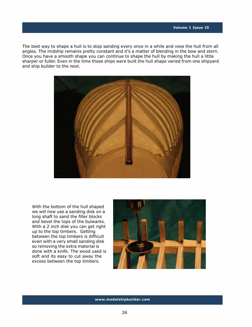
The best way to shape a hull is to stop sanding every once in a while and view the hull from allangles. The midship remains pretty constant and it’s a matter of blending in the bow and stern.Once you have a smooth shape you can continue to shape the hull by making the hull a littlesharper or fuller. Even in the time these ships were built the hull shape varied from one shipyardand ship builder to the next.
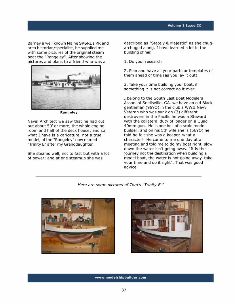
With the bottom of the hull shapedwe will now use a sanding disk on along shaft to sand the filler blocksand bevel the tops of the bulwarks.With a 2 inch disk you can get rightup to the top timbers. Gettingbetween the top timbers is difficulteven with a very small sanding diskso removing the extra material isdone with a knife. The wood used issoft and its easy to cut away theexcess between the top timbers.

Volume I Issue IX
www.modelshipbuilder.com
27
The deck has a pronounced sheer andalso a curve from side to side. Use thetops of the bulkheads as a guide andsand the blocks level with the bulkheads.With the blocks sanded down level,lightly sand off the laser char across therest of the bulkhead. Be careful tomaintain the curve of the deck and don’tsand the bulkhead tops flat.

Volume I Issue IX
www.modelshipbuilder.com
28
Finally the bottom section of the hull has been shaped to our satisfaction and the deck isfinished being sanded. Notice the top timbers still have not been sanded. Shaping of the hullstopped at the deck level and finishing of the top timbers will come after the deck and insidehave been sanded. The red arrow is pointing to the sheer line. This is the curve the outsideplanking will follow.
This now ends stage two of the Matthew build, in part 3 a waterway will be added along with
the keel, stem and sternpost. Also the top timbers will be completed.
The following is, purportedly, the transcript of an ACTUAL radio conversation between a United
States’ naval ship and Canadian authorities off the coast of Newfoundland.
Canadians: Please divert your course 15 degrees to the South to avoid a collision.
Americans: Recommend you divert your course 15 degrees to the North to avoid a collision.
Canadians: Negative. You will have to divert your course 15 degrees to the South to avoid a
collision.
Americans: This is the Captain of a US Navy ship. I say again, divert YOUR course.
Canadians: No. I say again, YOU divert YOUR course.
Americans: This is the Aircraft Carrier USS Lincoln, the second largest ship in the United States’
Atlantic fleet. We are accompanied by three destroyers, three cruisers, and numerous support
vessels. I demand that you change your course 15 degrees north. I SAY AGAIN, that is one five
degrees north, or counter measures will be undertaken to ensure the safety of this ship.
Canadians: This is a lighthouse, SIR. It’s YOUR call.
A little Humor

Volume I Issue IX
www.modelshipbuilder.com
29
Building The Bluenose IV“The Beginning”
By Michael J Brown
Background
In a previous issue, Winston mentioned that a Nova Scotian shipyard had been selected to buildthe Bluenose III. Starting with this issue, he has asked me to write a regular column to keep ourreaders up to date on the progress of the Bluenose construction.
First of all, some background. There is some controversy over the construction of this vessel byJoan Roué, the great-granddaughter of the original Bluenose designer, William J. Roué. NovaScotia tourism officials apparently question the need or desirability of replacing the existingBluenose II, arguing that the current vessel “will be seaworthy for a good many years” i (eventhough she was already retired once in 1994 and never expected to sail again). The Province ofNova Scotia also owns the trademarks “Bluenose”, “Bluenose II” and “Bluenose III”, and areconcerned that there might be some confusion with having two similarly-named vessels at sea atthe same time and serving similar rolesii.
Joan Roué, however, firmly believes that if the schooner is not built now, it may never be built,or at least not by Canadians. Wooden ship building skills are deteriorating or disappearing, withfew shipwrights remaining who have the skills to successfully undertake a project of thismagnitude. Further, the Province does not have a contingency plan should the Bluenose II beseverely damaged, or even lost. If this were to happen (keeping in mind the Cutty Sark fireearlier this year) then, without Joan’s initiative, the legacy of the Bluenose would be at risk ofbeing lost forever.
In line with her convictions, on 30 August 2006 Joan formed a company, Queen of the NorthAtlantic Enterprises (QNAE), to build the Bluenose IV. She also announcediii that the schoonerwould be built by Snyder’s Shipyard in Dayspring, Lunenburg County, NS, using the original designby William J. Roué. The keel is scheduled to be laid down on 1 July 2008 and launching isscheduled for 24 July 2010. In the words of the builders “This new Bluenose replica is to be ahistorically accurate world-class working vessel, a self-sufficient operation capable of travelingglobally promoting her legacy, and her home.” iv
The Shipyard
Since construction on the schooner will not actually start until next year, the next few issues willfocus on the shipyard, the designer, the people behind the project, and all those myriad ofdetails required to prepare for actual construction.
Snyder’s Shipyard first came into being in 1876 as Leary’s Shipyard. In 1944, it was purchasedby Reginald “Teddy” Snyder, who changed the name to what it is today. Snyder’s Shipyard, manyof whose shipwrights are second and third generation in their trade, did the repairs required tobring the Bluenose II out of what was expected to be permanent retirement and back to beingthe ultimate Canadian sailing icon. Two of Snyder’s current shipwrights, Brian and Gary Hirtle, aresons of one of the shipwrights who built the Bluenose II. Brian is also a model ship builder, andhas been a member of the South Shore Ship Modeller’s Guild since 1998.

Volume I Issue IX
www.modelshipbuilder.com
30
Snyder’s has already started building the infrastructure required for a project of this magnitude(don’t forget, the Bluenose is 112’ at the waterline). Figure 1 (below left) shows the 90’x32’lofting platform that will be used for laying out the schooner’s lines, while Figure 2 (below right)shows the beautiful site along the LeHave River where the new construction building for theBluenose will be built after her keel has been laid.
Fig.1 Lofting Platform(note Bluenose Sloop in Background)
Fig.2 Future Construction Site
The Plans
One of the most interesting and critical items in building either a ship and a model is, of course,the plans. Vernon Shea, noted as “one of a handful of marine draughtsmen left in the province ofNova Scotia that does his work by hand,” is drawing up the plans for the Bluenose IV. TheBluenose IV is being designed using the original lines, although, as a sail training and day chartervessel, she will be built to current commercial standards.
Queen of the North Atlantic Enterprises has posted two of Vernon Shea’s drawings on theirwebsite (see figure 3 & figure 4 next page) and is offering a high quality poster of the schooner’sgeneral arrangement (Figure 4) for $35.00 (P&H in North America included). To reserve a copy,send an e-mail to [email protected]; including your name, contact email address andphone number.
Dates in American Naval History
10 November 1775 - Congress votes to raise two battalions of Continental Marines, thusestablishing the Marine Corps.
13 November 1776 - Captain John Paul Jones in Alfred with brig Providence captures Britishtransport Mellish, carrying winter uniforms later used by Washington’s troops.
18 November 1890 - USS Maine, first American Battleship, is launched

Volume I Issue IX
www.modelshipbuilder.com
31
Fig.3 Profile & DecksUsed by Permission © 2007 QNAE
Fig.4 General ArrangmentsUsed by Permission © 2007 QNAE

Volume I Issue IX
www.modelshipbuilder.com
32
Modelling the Bluenose
QNAE is developing a set of plans specifically with model builders in mind. These will be the firstever official model plans, based on William Roué’s original plans and modified as necessary toreflect the schooner as built. Vernon Shea is doing a lot of research to ensure the drawings’accuracy and will also be doing the drawings himself. These plans are expected to be available atthe end of 2007. Further details will be provided when known.
The Way Ahead
This series of articles will track the construction of the Bluenose IV over the next 2-3 years. Aswith all ship building, both models and real, there will be periods of intense activity followed byperiods of slow progress. However, I will attempt to provide new and fresh material each monthbetween now and her first day at sea. Next month, I will be profiling the people behind thisproject – Joan Roué, Vernon Shea, some of the shipwrights doing the work, and others. Thefollowing month, I expect to show you just what goes into drawing the plans for a 1:1 model.
Those interested in following this construction might alsobe interested in reviewing the construction of theBluenose Sloop, also being built by Snyder’s Shipyard.
The Bluenose Sloop will be a 23’ 5” day sailor. It is basedon a series of very popular sloops built over the period1945 to 1972.
The original sloops were designed by William J. Roué, basedon the Bluenose lines.
Further historical details and design facts are available on the WJ Roué website. Thesesloops will be available for purchase from Snyder’s Shipyards.
The Bluenose Sloop
To the left we can see the linesfor the sloop being laid out inthe Bluenose IV lofting shed.
As you can see in the picture onthe right the sloop is really justa 1:1 scale model.
You can get the plans to build a smaller model of the Bluenose Sloop by sending an e-mailto [email protected]. In my opinion, this sloop would make a very interesting, butrelatively simple, scratch built model.

Volume I Issue IX
www.modelshipbuilder.com
33
Grogby Gene Bodnar
Everybody knows that grog is a mixture of plain water and rum, a sort of watered-downdrink doled out to British sailors from time immemorial, but few of us have any idea as towhere the term “grog” originated.
A poem written by Thomas Trotter in 1781 tells about the naming of grog:
A mighty bowl on deck he drew,And filled it to the brink;Such drank the Burford’s gallant crew,And such the gods shall drink,The sacred robe which Vernon woreWas drenched within the same;And hence his virtues guard our shore,And Grog derives its name.
This ditty was written 41 years after the actual creation of the term “grog.” In 1740,British Admiral Edward Vernon, who was commander-in-chief of the West Indies, orderedthat the daily ration of rum for his sailors be cut with water. Admiral Vernon always worea grogram coat, which was a coarse, loosely woven fabric of silk and mohair. Because ofthe coat he continuously wore, his men nicknamed him “Old Grog.” Of course, his mencould have mutinied when he cut out their full ration of rum, but they didn’t. Instead,they called the new drink “grog” after the admiral. They must have been fond of him.
Since that time, grog has been issued regularly to all sailors in the British Navy. Originally,sailors received a quarter of a pint, twice daily, along with a pint of water. As timepassed, this ration was reduced to one issue per day in 1824, and finally to a half-gill aday in 1850. Officers in the British Navy were completely cut off from grog rations in1881. Warrant officers were cut off in 1918. Finally, grog rations to all ratings ended onJuly 31, 1970.
The distribution of rum was once quite a ritual in the British Navy. At 11 a.m. theboatswain’s mate would pipe “Up spirits.” The ship’s cooper and a detachment of RoyalMarines would proceed to unlock the spirit room. Two marines would lift the keg to thedeck. In single file, a group of cooks from the petty officers’ messes would hold out theirmugs while the sergeant of marines poured out the ration under the direction of the chiefsteward. The rest of the rum was mixed in a large tub with two parts water, whichbecame the grog served to the ratings.
One of the reasons for the continual reduction in grog rations over time was the fact thatsailors would frequently save up their run rations for several days, then drink them all atonce.

Volume I Issue IX
www.modelshipbuilder.com
34
The practice of serving a grog ration twice a day was adopted by the Continental Navyby Robert Smith, who was then Secretary of the Navy. He experimented with sub-stituting rye whiskey for the rum. American sailors liked it so much that Smith made thechange permanent. Thus, “grog” became known as “Bob Smith” in the American Navy.
Would you like to taste an authentic ration of grog to see what it was like? You canmake your own. Remember to serve it at room temperature – they had no ice cubesaboard sailing ships of old. The Royal Navy probably didn’t spend a lot of money on rum,so make sure you buy the cheapest, nastiest rum your can find. Then add four parts tapwater. You might not keep your friends around very long, but at least you can say youtried grogg
Rotary Power Carving Techniquesby Bill Short
Carving Ornamentation for Ship Models
A spiral bound booklet with an acetate cover, stiff board back, fullcolour cover page and the rest of the 52 pages are printed in blackand white with high quality photos on 70# Hammermill paper. Itwill lie flat on your bench and can be folded over on itself to a onepage size.
The booklet, which covers in detail, carving with rotary tools anddental burrs, is available for immediate shipment. It is 52 pagesand has over 50 high definition digital photographs detailing thestep-by-step carving lessons in both bas-relief and carving-in-the-round.
Table of ContentsIntroduction
Chapter 1 The tools available to rotary carveChapter 2 Wood selection for carving ornamen-
tationChapter 3 Visualization
Chapter 4 How to rotary carveChapter 5 Carving complex shapes
Chapter 6 Finishing the carvingChapter 7 Safety Considerations
BibliographyIndex
Now also includes a bibliography of very goodreference books on ornamentation which
covers the methods used in carving several ofthe complex carvings found on my model of
The Sovereign of The Seas.
The selling price of the booklet including air mailpostage and handling is:
Destinations in the USA and Canada $30.00 US FundsDestinations in the UK and overseas: $36.00 US
Funds*Prices effective July 1, 2007
Payment must be in the form of a US Money Order orInternational money order in US dollars. As I am nota business, my bank cannot handle personal checksin other currencies, or other forms of payment. As
you already know, it is not advisable to send cash inthe mail for obvious reasons.
Mail your payment at your convenience to:
Bill Short3 Karsam Court, SS1,
Niagara-on-the-Lake, OntarioL0S 1J0Canada
For more information email:[email protected]

Volume I Issue IX
www.modelshipbuilder.com
35
Ships From The Past
HMS DuncanThe Duncan was a 1st Rate Ship-of-the-line built in 1859, and the third tobear that name. Her armamentconsisted of 38 x 8" guns and 62 x32pdr. She was renamed Pembroke in1889.
HMS HoweHowe was a screw Royal Navy 110-gun 1st rate ship of the line, namedafter Admiral Richard Howe. Howewas launched 13th March 1860,renamed Bulwark, and then renamedImpregnable 27th September 1886.Howe was sold in 1921
USS Crusadera 545-ton (burden) wooden screwgunboat, built at Murfreesboro,North Carolina in 1858 as the civiliansteamship Southern Star. She waschartered by the Navy in October ofthat year to take part in a punitiveexpedition to Paraguay.Commissioned as USS Southern Star,she operated in South Americanwaters during the first three monthsof 1859, then returned to the UnitedStates. The Navy purchased thesteamer at about that time andchanged her name to Crusader.

Volume I Issue IX
www.modelshipbuilder.com
36
Contributor’s PicturesSend your pictures to [email protected]
First this month are some pictures fromTom Eagles. At first I was just going to post
some pictures but Tom provided such aninteresting story on the build I couldn’t help
but include it here.
Trinity E.
“... when I moved to SC I started tobuild an elevated 7/8N2 Steam poweredOutdoor RR, in an L shaped design, point topoint or better said "Turntable to Turntable"about 180' in length. I was trying to do a nicelooking job of it so as not to create aneyesore in my neighborhood.
Without any warning or due process I wasserved with a "Court ordered Cease & DesistNotice" at the behest of the dreaded HomeOwners Association.
When questioned they said they found anOutdoor Steam RR to be an "AttractiveNuisance."
Well after being in a foul state of mind for afew weeks I approached them to see if I coulduse the (3) Lakes or mud ponds that the sub-division I live in is named after, for modelsteamboating (steam one way or another!)
After meeting with them they said yes as
that was a much more gentlemanly pursuitand I could use the ponds. So I guess thatmakes me somewhat of a “gentleman” now?
Well being part Irish and part “Bull” in a Chinashop I rushed out to build a steam boat in myusual “haste makes waste mode”.
I found a set of plans in the August/October1997 issue of Garden Railway and off wewent.
If I would have not been in such a hurry"Cart before the Horse!" I would have donesome research and Prior Planning to PreventPI-- Poor Performance.
When the hull was done it was determinedthat there was not enough room for all themachinery in the deck house area and that Iwould have to encroach on the area of thePilot House.
I contacted the preparer of the plans Mr.Ted Stinson, since they were originally 1" =1'and designed for an electric (battery)powered electric motor and (2) channel RC Iasked him about the problem.
He allowed that he cut out a few feet to fitthe pages of "GR". After contacting Mr. Pete
Volume I Issue IX
www.modelshipbuilder.com
37
Barney a well known Maine SR&RL's RR andarea historian/specialist, he supplied mewith some pictures of the original steamboat the "Rangeley". After showing thepictures and plans to a friend who was a
Rangeley
Naval Architect we saw that he had cutout about 50' or more, the whole engineroom and half of the deck house; and sowhat I have is a caricature, not a truemodel, of the "Rangeley" now named"Trinity E" after my Granddaughter.
She steams well, not to fast but with a lotof power; and at one steamup she was
described as "Stately & Majestic" as she chug-a-chuged along. I have learned a lot in thebuilding of her.
1, Do your research
2, Plan and have all your parts or templates ofthem ahead of time (as you lay it out)
3, Take your time building your boat, ifsomething it is not correct do it over.
I belong to the South East Boat ModelersAssoc. of Snellsville, GA. we have an old Blackgentleman (96YO) in the club a WWII NavyVeteran who was sunk on (3) differentdestroyers in the Pacific he was a Stewardwith the collateral duty of loader on a Quad40mm gun. He is one hell of a scale modelbuilder; and on his 5th wife she is (56YO) hetold he felt she was a keeper, what acharacter! He came to me one day at ameeting and told me to do my boat right, slowdown the water isn't going away. "It is thejourney not the destination when building amodel boat, the water is not going away, takeyour time and do it right". That was goodadvice!
Here are some pictures of Tom’s “Trinity E.”

Volume I Issue IX
www.modelshipbuilder.com
38

Volume I Issue IX
www.modelshipbuilder.com
39
Next are some pictures from Janos (John) Nemeth
Duyfken: scratch built 1:40, using mostly Southern Myrtle. Plank on bulkhead, single layerplanking, following the Dutch planking and scarphing method. Decks: lime wood, again following
the Dutch way building the waterways. Rudder and whipstaff ‘working’. Decorations nearlyexclusively self made, I used just a few commercially available items (gun barrels, flags, belayingpins). A section of the poop deck had been left without planks to show some interior. I am about
to replace some carved decorations with better ones (lion etc). I seem to be able to acquiresome better quality wood (pear, boxwood) just now.
Grosse Yacht: scratch built some 30+ years ago and re-planked now. POB, planks walnut, decksTanganyica. Decorations: mostly carved, from pear wood. I used some Amati scrolls which aregoing to be replaced by hand carved scrolls later. Guns and spars have yet to be installed and
some rigging is still on its way.

Volume I Issue IX
www.modelshipbuilder.com
40
What Ship is This????Know your ships? Here’s a little trivia for you. Send your guesses to
[email protected] and check back in the next issue to see if you wereright!
Last Issue - (16 people were able to name this ship)
HMCS SAGUENAY survived both a torpedoing by an Italian subma-rine in 1940 and a collision with a merchantman off Cape Race in1942. In the collision her depth charges were set off, and most ofher stern was blown away. After this, she could never be re-paired well enough for sea duty, and she spent the rest of thewar as a training ship at Cornwallis, NS.
Model Ship ForumsJoin a modeling community today!
Ship Model Forum - www.shipmodeling.netModel Ship World - www.modelshipworld.comDryDock Models - www.drydockmodels.com
Model Boat Mayhem - www.modelboatmayhem.co.ukLauck Street Shipyard Forum - www.lauckstreetshipyard.com
The ship in the background is HMCS Protecteur. What is the ship in the foreground?

Volume I Issue IX
www.modelshipbuilder.com
41
Aboard HMS Victory by Gene Bodnar
Across1 Spider's construction4 Make a go of it8 Sonar pulse12 Neutral middle vowel17 Mature18 Prophetic sign19 Region20 Sticks one's nose where itdoesn't belong21 Grabbies, on HMS Victory23 Time that a day begins onHMS Victory24 Corrodes, as steel25 Defoe's __ Flanders26 Enthusiastic admirer27 Merrier29 Sleep like __31 __ Downs (where the Derbyracehorse is run)34 Hooting bird35 Kind of bean38 Number of commissionedofficers aboard HMS Victory39 He slept in a coffin-like cotaboard HMS Victory42 Hair styling cream43 Essential oil from flowers45 "__ always something!"46 Hog's home47 Gaelic alphabet49 British dominion over India
51 Flower necklace53 Capri's "Blue __"54 Writer John __ Passos57 Makes rugs60 Extinct bird of New Zealand62 Prostrated63 Made a laborious living65 Punishable offense aboardHMS Victory, except for thecook*
67 One of the Flintstones
68 Good-bye, in Italia69 Sigmoid70 Astronaut Collins72 Sra., in Boston73 Of an anatomical cavity75 Ornamental vase76 Droop78 Of the nose79 Adjust a spark plug81 Greek vowel84 Nocturnal critter of SouthAmerica88 Number of masts on aschooner89 What could be expected ifthe crew was assembled on thequarterdeck at 11 a.m.93 Fashion94 Free from danger96 Regrettable
97 Site of a WorldWar II conference98 Indistinct form99 Pixies101 Beige102 Trust104 Theaterproduction106 Nelson said hewas the "greatest seaofficer I ever knew"108 Term formaggots, aboard HMSVictory112 Artist's tripod113 Brink114 Mental concept115 Cenozoic __116 "Guess __ I'vebeen"117 Caspian and Dead118 Mary Lincoln'smaiden name119 Ten-percenter, forshort
Down1 Existed2 Conscious self3 "The ChampionshipTrack," in horse racing4 Wind into loops5 Beaten egg dish6 __ capita7 Printer's measures8 Stiff straw hat9 Magnetic metal10 __-Platonism11 Entrance in aship's side12 Agile13 Monsarrat's The__ Sea14 What Nelson lostat the Battle of SantaCruz15 Saturated16 Donkey's kin22 Corner of a pageturned down26 Forward upperdecks, for short28 __ Baba29 Literary collection30 Illuminated32 Letter after upsilon33 Hardened34 New York Giantshero Mel36 More substantive37 Oval-shaped nuts40 Letter after chi41 Neither's partner44 Unprocessed
48 Arnie's game50 Diamond, for one52 Organic compound53 Tokens ofchallenge54 Pours, as wine55 Largest of theRyukyu Islands56 Latrines, aboardHMS Victory58 Expressions ofbliss59 Parisian face60 Wire measure61 Single64 Maar who posedfor Picasso66 Public utilityelectrician71 "Unforgettable"singer Cole74 Grossglockner, forone75 Optimistic attitudes77 Take a chance79 Grinds, as theteeth80 Helping hand82 __ Aviv83 Colonial insect85 Naturally occurringsynthetic86 Bachelor's lastwords87 "Johnny __"(Confederate soldier)90 Consumption91 Group of stars inTaurus92 Covered with thickblack liquid95 Fudd of the comics100 Valley101 Forum wear103 Shout ofamazement104 Water droplets ongrass105 "Go team!"107 Pindaric specialty108 Seized with theteeth109 Much __ AboutNothing110 Before, in poetry111 Snooze
*The cook wasallowed to do this sohe wouldn’t spit in
the food whilecooking it.

Volume I Issue IX
www.modelshipbuilder.com
42
Aboard HMS Victory Answers