The MSB Journal
28
The MSB Journal March 2007 In This Issue: - Selecting Saw Blades - Frame Lofting Practicum - Part I - From the files of ShipWreckCentral and more...
-
Upload
hugo-kulman -
Category
Documents
-
view
25 -
download
0
description
Modelismo
Transcript of The MSB Journal
The MSB Journal
March 2007
In This Issue:- Selecting Saw Blades
- Frame Lofting Practicum -
Part I
- From the files of
ShipWreckCentral
and more...

The MSB Journal www.modelshipbuilder.com
1
Volume 1, Issue 1
March 2007
© www.modelshipbuilder.com
All articles published in The MSB Journal are covered under international copyright laws.
This newsletter may be re-distributed freely as long as it remains,
whole, intact and un-altered. We also urge you to print a copy for your workshop or reading area.
Published by www.modelshipbuilder.com
Front Cover
Photo
Mr. John Reid
Montreal, Quebec, Canada
How to Contact The MSB Journal
By email: [email protected]
By Snail-Mail
ModelShipBuilder.com
c/o Winston Scoville 5 St. Charles Place RR 5 Clinton, Ontario, N0M 1L0
Canada
The MSB Journal www.modelshipbuilder.com
2
In This Issue
EDITORS NOTES.................................................................................................3
LETTERS TO THE EDITOR.................................................................................4
SO YOU WANT TO BUILD A MODEL SHIP? .....................................................5
SHIP MODELS ON THE INTERNET....................................................................7
SELECTING SAW BLADES FOR YOUR TABLE SAW ......................................9
SHIPS FROM THE PAST...................................................................................14
JIGS& THINGS...................................................................................................15
HISTORICAL SHIPS OF ANOTHER NATURE..................................................16
FRAME LOFTING PRACTICUM – PART I ........................................................17
FROM THE FILES OF SHIPWRECKCENTRAL ................................................23
CLUBS & ORGANIZATIONS WITH A WEB PRESENCE .................................24
THE MSB JOURNAL CLASSIFIEDS.................................................................25
NAUTICAL ENTERTAINMENT..........................................................................26

The MSB Journal www.modelshipbuilder.com
3
Editors Notes Winston Scoville [email protected] Welcome to the inaugural issue of The MSB Journal. An online magazine style newsletter created by Model Ship Builders for Model
Ship Builders.
We hope that you enjoy your reading experience and we encourage you to send us
comments or suggestions for future issues. To help make this a truly reader friendly newsletter we hope that you will take part in its development. This can be done in numerous ways, from merely dropping us a
line of encouragement, submitting articles, recommending future articles and content, to simply passing on the word about where people can download their copy of The MSB Journal.
Have a flair for writing? We’re also looking for regular columnists covering all areas of model building. Share your knowledge so that others may learn.
Maybe you’re not a writer, but have an interesting project on the go. Contact us with the details and we’ll see what we can do. All input is welcome. How you participate is up to you. The most important aspect is that you participate.
Okay, enough from me….lets get on to the newsletter, there’s lots of great information in this issue.
To contact us:
To subscribe to The MSB Journal: www.modelshipbuilder.com/msbjournal

The MSB Journal www.modelshipbuilder.com
4
Letters to the Editor Letters to the editor will be published in this section. For obvious reason you don’t see any here
this month. Send us your emails and we’ll post them here. Have questions? Comments? Or are
just looking for information? Let us know by sending an email to
.
The MSB Journal www.modelshipbuilder.com
5
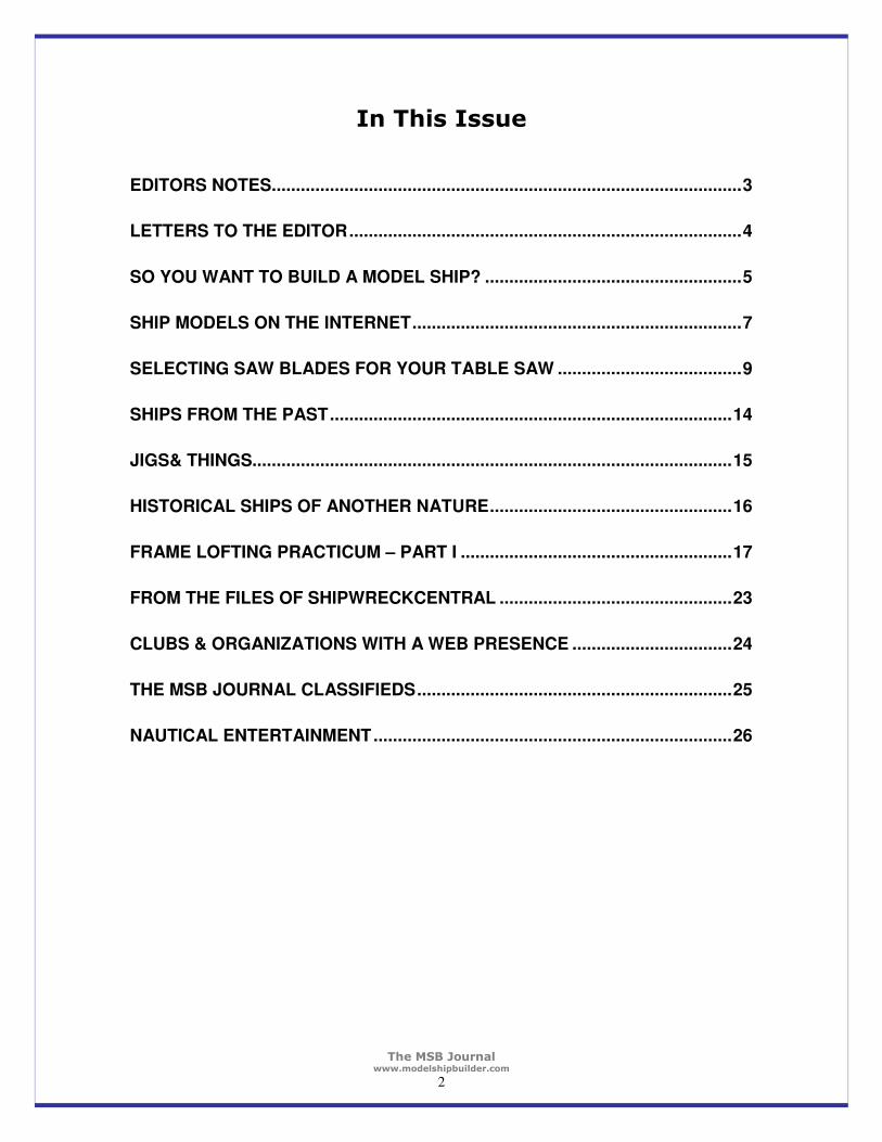
So you want to build a model ship?
So you want to build a model ship? You looked around went to all the shops or visited all the stores online and you’ve decided that you’d like to build the HMS Victory as your first build. Its got everything you’ve always
wanted in a model ship, lots of lines and things, lots of cannons, beautiful looking wood…boy is that ever going to look good in your office. So you go out and pay
$500.00 for the kit and begin to build…….. Sadly, this is what a lot of potential model builders do, only to be frustrated by the level of skill that is required
to build the model of that level not to mention the hundreds if not thousands of hours that can go into building it. So much so, that a lot of once enthusiastic people turn their backs on model building never to
return, thinking that it is above and beyond them. The fact is, like anything that is worth doing well, there
is a learning curve. We all have to start somewhere and the absolute best place to start is with the very basics. Model building in an ongoing life long experience. You will never know all there is to know. This became
apparent to me recently when a good friend of mine was getting to the rigging portion of his build. He was stumped. It took him a couple of weeks to figure things out. That surprised me due to the fact that he has been building models now for over
50 years. So where do we start to learn? Well, I do not proclaim this to be to do all to end all but if I might be so humble as to make some suggestions…
First, you should do some reading on the subject. This should give you a solid foundation on what will be required of you or at least an outline of the basic minimum skills you’ll need to master. A couple of books that I have found quite
helpful and would have no trouble recommending are “Historic Ship Models by Wolfram zu Mondfeld” (ISBN 1-4027-2186-2) and “Ship Modeling from Stem to Stern by Milton Roth” (ISBN 0-8306-2844-4). You should be able to find these books at
any well stocked bookstore or hobby shop (If not we have them available through the bookstore at our website…I know…shameless plug). I would also recommend that you get in touch with other model builders and get
suggestions from them. You can do this by attending a local meeting at a modeling club in your area or through the internet where you will find many discussion forums that are very active.
So you’ve done some reading and you want to get started. Which model should you select as your first build? Most model manufacturers offer models that are geared towards the novice builder. Have a look at their offerings and see which ones appeal
to you. For your first model, try to keep it as simple as possible while still maintaining your interest.

The MSB Journal www.modelshipbuilder.com
6
Being able to complete a model at this level will provide you with some of the basic skills you need for taking on that next project. Here to, do not leave yourself to the
whims of the instructions that you get with this kit. Check around and see what others have done, see if they’ve encountered any problems with their build and how they overcame them. Though not intentional you will find that a lot of model kits leave a lot to be desired when it comes to their instructions. Especially those that are
created in a different language and have to be translated as they can lose a lot of their meanings in the translations. Another learning aide for you to be aware of are Practicums. These are highly
detailed instruction manuals that are written by model builders and are based on a given or specific kit.
Regardless of how you start it is important that you do some homework before you go jumping off the deep end. Doing so will help you avoid spending money needlessly on a model that is way beyond your current capabilities. Don’t worry, you’ll get to build that highly detailed HMS Victory down the road when you are
ready for it and you’ll be a lot happier with the results of your efforts. In the next issue, we’ll have a look at some of the basic tools that you’ll need in your
shipyard tool-bin…
Recommended Reading Material
All books available through www.modelshipbuilder.com
or any well stocked hobby shop

The MSB Journal www.modelshipbuilder.com
7
Ship Models On The Internet Sid Siegal, John Green, [email protected]
As ship modelers what do we want to see on the Internet? I’m sure every ship modeler can give a different answer. Obviously, the web is a major portal to historical research. It’s also a great way to find technical answers and assistance.
But there’s another facet of the web that is very important: to recognize achievement and excellence in the art of ship modeling.
Ship modeling is an art that demands knowledge and understanding of history and maritime technology as well as skilled craftsmanship. Authentic ship models are rare and not
readily available for viewing. But looking at ship models is one of the best ways for modelers to improve the quality and
sophistication of their work. There are many websites that show images of ship models, but
few that accurately and succinctly describe the model or provide a possible source for further research. Often there is much about the history of the subject ship, but little about
the model itself, beyond the vague description that it is “museum quality”, whatever that means.
John Green of Maritime Ship Modelers Guild in Halifax, Nova Scotia, and Sid Siegel of Ship Modelers Association of Southern California established a couple of websites to give independent ship modelers an opportunity to exhibit their work. The Marine Model Artists Cooperative (www.shipmodelco-op.com) was structured as a sort of
exchange or venue where excellent ship models by independent builders are accurately described and offered for sale, without commission or fees of any kind. The purpose was not just to sell models, but to educate the public that fine authentic ship models are rare and valuable,
and to try to counter the public impression that ship models come out of a box and are all pretty
much alike and not worth more than the price of a good bowling ball. For those modelers who do not care to sell their models, the
Ship Model Registry (www.registryofshipmodels.org) offers the opportunity to have their
work exhibited in a more academic venue and become part of a database for future research. This is a new website and actively seeking participants who wish to record and exhibit
their completed models or even show any heirloom models in their possession. Both websites are meant to be used as research sources, or simply to show other
The MSB Journal www.modelshipbuilder.com
8
modelers’ takes on various subjects. One obstacle to these enterprises has been the difficulty of getting good photographs that do justice to the models.
There are many websites that feature ship models, and it is not easy to get attention in crowded cyberspace. We hope the above entries will be useful to independent ship modelers in reaching their colleagues as well as the general public.
Sid Siegel John Green
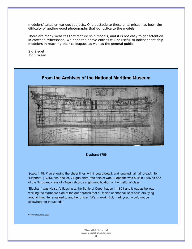
From the Archives of the National Maritime Museum
Elephant 1786
Scale: 1:48. Plan showing the sheer lines with inboard detail, and longitudinal half-breadth for
‘Elephant’ (1786), two-decker, 74-gun, third-rate ship of war. ‘Elephant’ was built in 1786 as one
of the ‘Arrogant’ class of 74-gun ships, a slight modification of the ‘Bellona’ class.
‘Elephant’ was Nelson's flagship at the Battle of Copenhagen in 1801 and it was as he was
walking the starboard side of the quarterdeck that a Danish cannonball sent splinters flying
around him. He remarked to another officer, ‘Warm work. But, mark you, I would not be
elsewhere for thousands.’
Source: www.nmm.ac.uk
The MSB Journal www.modelshipbuilder.com
9
Selecting Saw Blades for your Table Saw Rockler Woodworking – www.rockler.com
When in your workshop, whether you are cutting wood on a large table saw or your
bench-top mini table saw it is important to select the most appropriate blade to do the job. In the following pages we are going to look at how to select just that blade. Understanding these basic elements of blade design will provide even the novice with enough information to properly select blades for their table saw needs in the
workshop. So how do I pick out the right saw blade?
Selecting saw blades isn’t really all that complicated, you just need to know a little about what different types of saw blades do best, and about what separates top-
quality saw blades from the rest of the pack. Saw Blade Basics
In general, regardless of their size, saw blades are designed to handle specific types of cutting operations. There are blades that are designed for crosscutting wood, ripping wood, cutting veneered plywood and panels etc. There are also “general
purpose” and “combination” blades, which are designed to work well in two or more types of cutting operations. There are a number of factors that determine what a blade does best.
� Number of teeth � Type of gullet � Tooth configuration
� and the hook angle Number of teeth
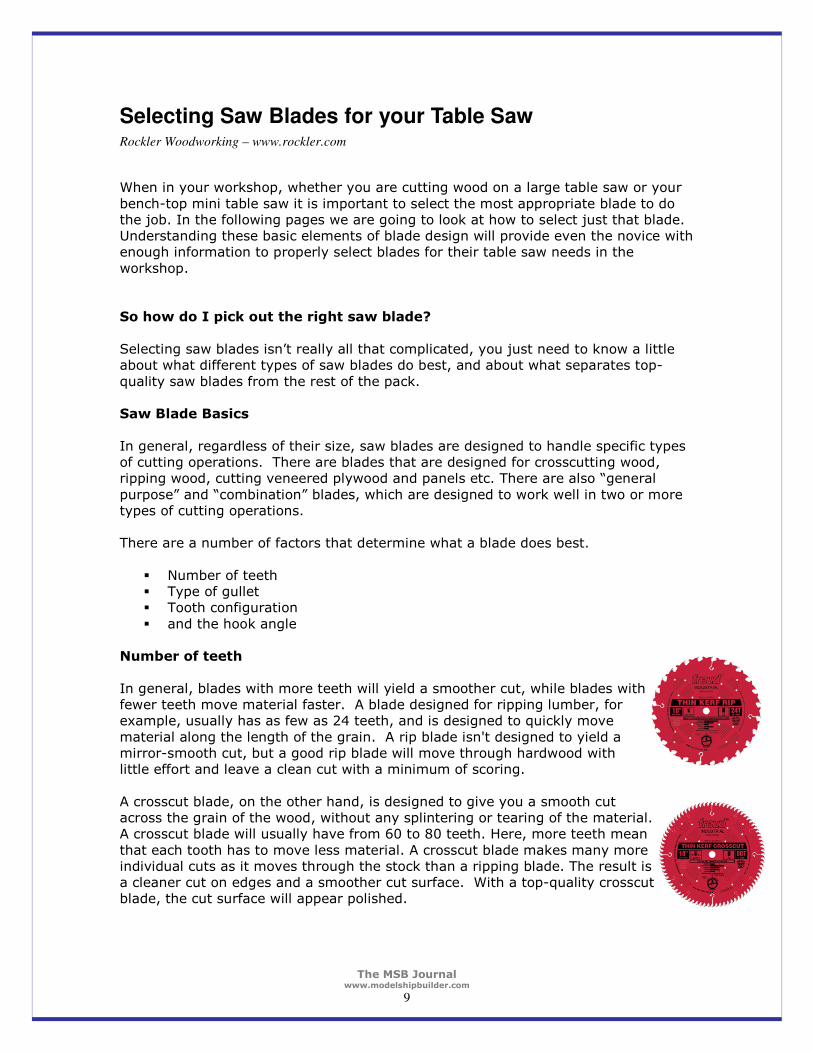
In general, blades with more teeth will yield a smoother cut, while blades with fewer teeth move material faster. A blade designed for ripping lumber, for example, usually has as few as 24 teeth, and is designed to quickly move
material along the length of the grain. A rip blade isn't designed to yield a mirror-smooth cut, but a good rip blade will move through hardwood with little effort and leave a clean cut with a minimum of scoring.
A crosscut blade, on the other hand, is designed to give you a smooth cut across the grain of the wood, without any splintering or tearing of the material. A crosscut blade will usually have from 60 to 80 teeth. Here, more teeth mean
that each tooth has to move less material. A crosscut blade makes many more individual cuts as it moves through the stock than a ripping blade. The result is a cleaner cut on edges and a smoother cut surface. With a top-quality crosscut blade, the cut surface will appear polished.
The MSB Journal www.modelshipbuilder.com
10
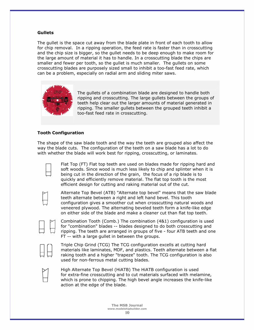
Gullets
The gullet is the space cut away from the blade plate in front of each tooth to allow for chip removal. In a ripping operation, the feed rate is faster than in crosscutting and the chip size is bigger, so the gullet needs to be deep enough to make room for the large amount of material it has to handle. In a crosscutting blade the chips are
smaller and fewer per tooth, so the gullet is much smaller. The gullets on some crosscutting blades are purposely sized small to inhibit a too-fast feed rate, which can be a problem, especially on radial arm and sliding miter saws.
The gullets of a combination blade are designed to handle both ripping and crosscutting. The large gullets between the groups of teeth help clear out the larger amounts of material generated in
ripping. The smaller gullets between the grouped teeth inhibit a too-fast feed rate in crosscutting.
Tooth Configuration
The shape of the saw blade tooth and the way the teeth are grouped also affect the way the blade cuts. The configuration of the teeth on a saw blade has a lot to do
with whether the blade will work best for ripping, crosscutting, or laminates.
Flat Top (FT) Flat top teeth are used on blades made for ripping hard and soft woods. Since wood is much less likely to chip and splinter when it is
being cut in the direction of the grain, the focus of a rip blade is to quickly and efficiently remove material. The flat top tooth is the most efficient design for cutting and raking material out of the cut.
Alternate Top Bevel (ATB) "Alternate top bevel" means that the saw blade teeth alternate between a right and left hand bevel. This tooth
configuration gives a smoother cut when crosscutting natural woods and veneered plywood. The alternating beveled teeth form a knife-like edge on either side of the blade and make a cleaner cut than flat top teeth.
Combination Tooth (Comb.) The combination (4&1) configuration is used for "combination" blades -- blades designed to do both crosscutting and ripping. The teeth are arranged in groups of five - four ATB teeth and one
FT -- with a large gullet in between the groups.
Triple Chip Grind (TCG) The TCG configuration excells at cutting hard materials like laminates, MDF, and plastics. Teeth alternate between a flat
raking tooth and a higher "trapeze" tooth. The TCG configuration is also used for non-ferrous metal cutting blades.
High Alternate Top Bevel (HiATB) The HiATB configuration is used for extra-fine crosscutting and to cut materials surfaced with melamine, which is prone to chipping. The high bevel angle increases the knife-like
action at the edge of the blade.
The MSB Journal www.modelshipbuilder.com
11
Hook Angle
On most saw blades, the tooth faces are tipped either toward or away from the direction of rotation of the blade, rather than being perfectly in line with the center of the blade. Hook angle is the angle formed between the tooth face and a line drawn from the center of the blade across the tip of the tooth. On a blade with a positive
hook angle, the teeth are tipped toward the direction of the blade's rotation. A negative hook angle means that teeth tip away from the direction of rotation, and a zero degree hook angle means that the teeth are in line with the center of the blade.
Hook angle affects blade operation in important ways. A blade with high positive hook angle (+20 degrees is a high hook angle) will have a very aggressive cut and a fast feed rate. A low or negative hook angle will slow the feed rate and will also
inhibit the blade's tendency to "climb" the material being cut. A blade for ripping lumber on a table saw will generally have a high hook angle, where an aggressive, fast cut is usually what you want. Radial arms saws and sliding compound miter saws, on the other hand, require a blade with a very low or negative hook angle, to
inhibit overly fast feed rate, binding, and the blade's tendency to try to "climb" the material.
Kerf Width and Plate Thickness
The width of the "kerf" -- the slot the blade cuts in the material - is another important consideration. Most obviously, the kerf width determines the amount of
material that is expended in the cutting process. But kerf width isn't just a matter of economics. The size of the kerf is determined in part by the thickness of the blade plate, and a solid, reliable blade plate is one of the features of a good saw blade.
Thin Kerf Blades
A saw blade's teeth, of course, have to make a
wide enough cut to allow the blade plate to pass through the kerf. And for the blade to operate smoothly and make a true cut without a lot of scoring on the edge of the cut, the blade plate has
to be substantial enough to absorb vibration and to handle the heat generated during the cut. For full kerf saw blade, a kerf width of around 1/8'' is
standard. But for so called "underpowered" saws -- under 3 HP for a table saw -- a full 1/8'' kerf has another effect: drawing too much power from the tool. If not enough power is delivered to
the blade, the saw slows down causing excessive friction. The blade heats up and can become distorted or burn the cut surface. Fortunately for woodworkers who don't own the most powerful industrial equipment -
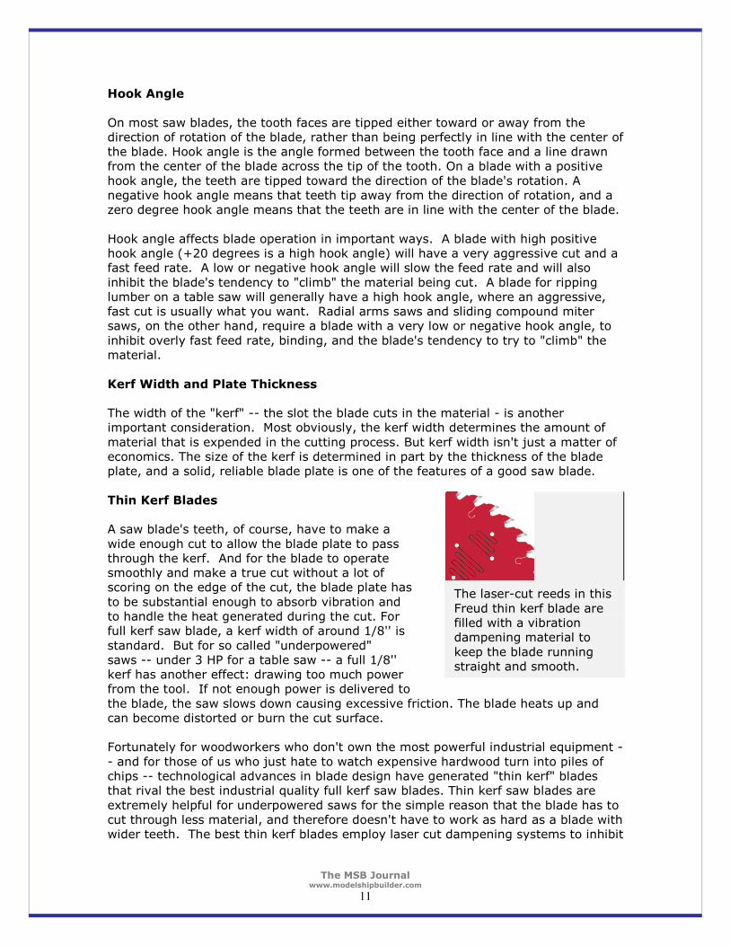
- and for those of us who just hate to watch expensive hardwood turn into piles of chips -- technological advances in blade design have generated "thin kerf" blades that rival the best industrial quality full kerf saw blades. Thin kerf saw blades are
extremely helpful for underpowered saws for the simple reason that the blade has to cut through less material, and therefore doesn't have to work as hard as a blade with wider teeth. The best thin kerf blades employ laser cut dampening systems to inhibit
The laser-cut reeds in this
Freud thin kerf blade are filled with a vibration dampening material to
keep the blade running straight and smooth.
The MSB Journal www.modelshipbuilder.com
12
vibration, and are made out of the best quality hardened steel to help them stay true in the face of high rotation speeds and stress generated in cutting.
Quality Makes the Difference
Now that you know how saw blades work, how do you judge the quality of individual
blades? It's important to be able to judge the quality of a saw blade -- how a saw blade performs depends on precision manufacturing techniques and on the quality
of the material that go into making the blade.
The Best Saw Blade Teeth
One of the most important things to look for in a saw blade is a good set of teeth. How
long the blade will stay sharp, how clean it will cut, and how many re-sharpenings it will take all depend on the quality of the cutting tips. These days, carbide has just about replaced steel as the material for cutting tips of saw blade teeth. But not all
carbide is created alike. On some of the best premium blades, the carbide is formulated specifically for the application of the blade. At minimum, look for a blade with C3 grade micro-grain carbide teeth, which are thick enough to allow a number or re-sharpenings. C4 carbide is the most durable grade for saw blade teeth, and is
usually found only on premium blades. A Quality Blade Plate
For a saw blade to make a true cut, the teeth must be held rigidly in line with one another. The blade plate needs to be as close to perfectly flat as possible, and it needs to stay that way during the cut. The blade plate should be made of quality,
hardened steel. The arbor hole also needs to be sized and placed with extreme precision. The best blade manufacturers like Freud and Forrest laser cut their blade plates to insure that the blade will fit the saw's arbor precisely and the teeth will maintain as close to a perfectly consistent path through the material as possible.
The blade plate also has to be "tensioned" for it to remain straight and rigid when it comes up to speed. On a high quality blade, correct tensioning keeps the blade from becoming "floppy" as result of the centrifugal force generated in operation. Blade
Plates can also be treated to make their surface resistant to picking up resin and adhesives from the materials they cut. For example, many Freud LU series blades have a permanent red Teflon coating to reduce friction and help them resist corrosion and resin build up.
Conclusion
Hopefully, the information above will prove helpful the next time you go to select a
new saw blade for your table saw. Remember, regardless of whether you need a 12” blade or a 2” blade, the same basic principles apply….Happy Cutting!
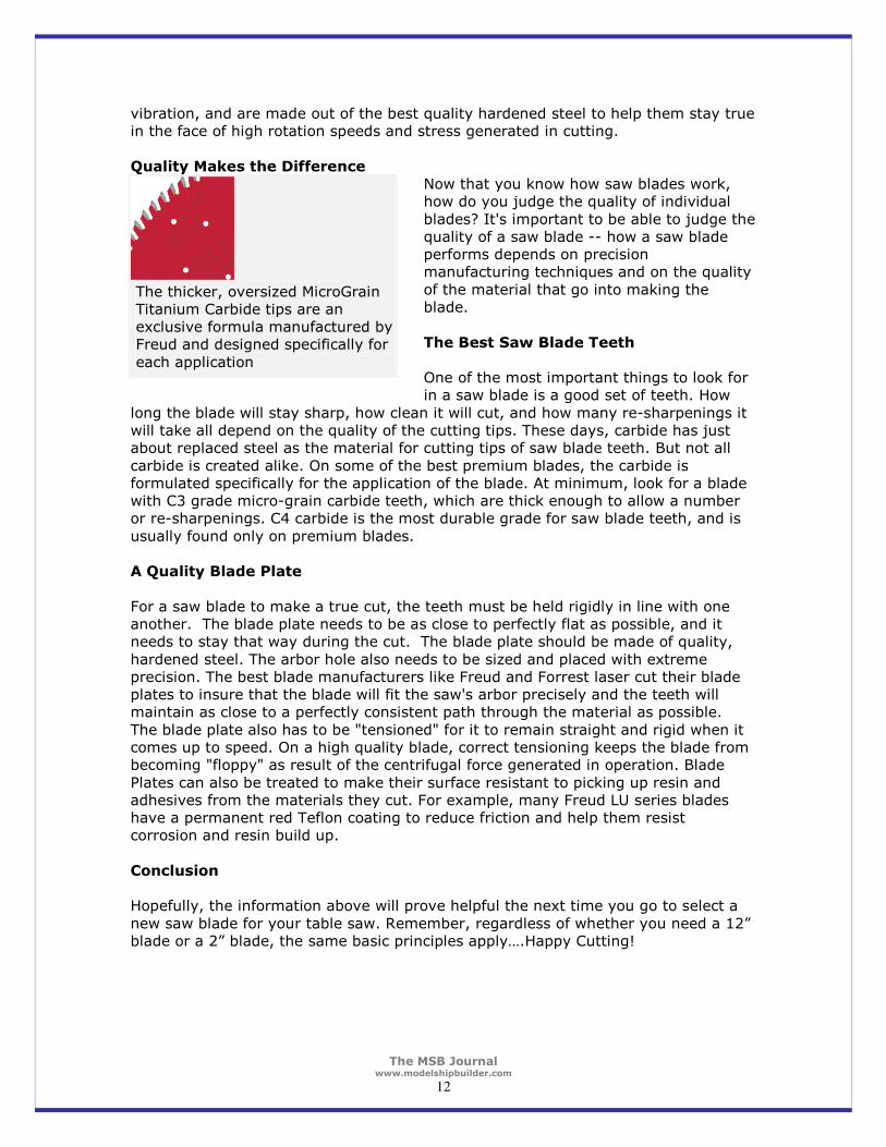
The thicker, oversized MicroGrain Titanium Carbide tips are an exclusive formula manufactured by Freud and designed specifically for
each application
The MSB Journal www.modelshipbuilder.com
13
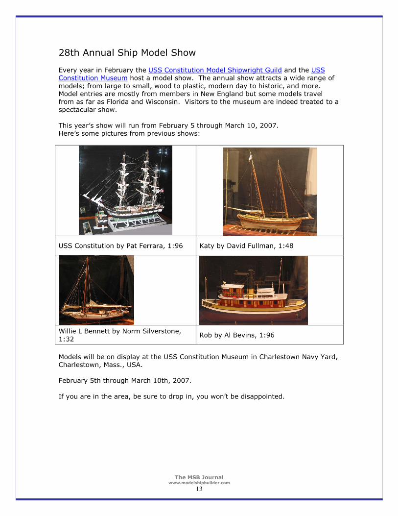
28th Annual Ship Model Show Every year in February the USS Constitution Model Shipwright Guild and the USS Constitution Museum host a model show. The annual show attracts a wide range of
models; from large to small, wood to plastic, modern day to historic, and more. Model entries are mostly from members in New England but some models travel from as far as Florida and Wisconsin. Visitors to the museum are indeed treated to a spectacular show.
This year’s show will run from February 5 through March 10, 2007. Here’s some pictures from previous shows:
USS Constitution by Pat Ferrara, 1:96 Katy by David Fullman, 1:48
Willie L Bennett by Norm Silverstone,
1:32 Rob by Al Bevins, 1:96
Models will be on display at the USS Constitution Museum in Charlestown Navy Yard, Charlestown, Mass., USA. February 5th through March 10th, 2007.
If you are in the area, be sure to drop in, you won’t be disappointed.
The MSB Journal www.modelshipbuilder.com
14
Ships from the past
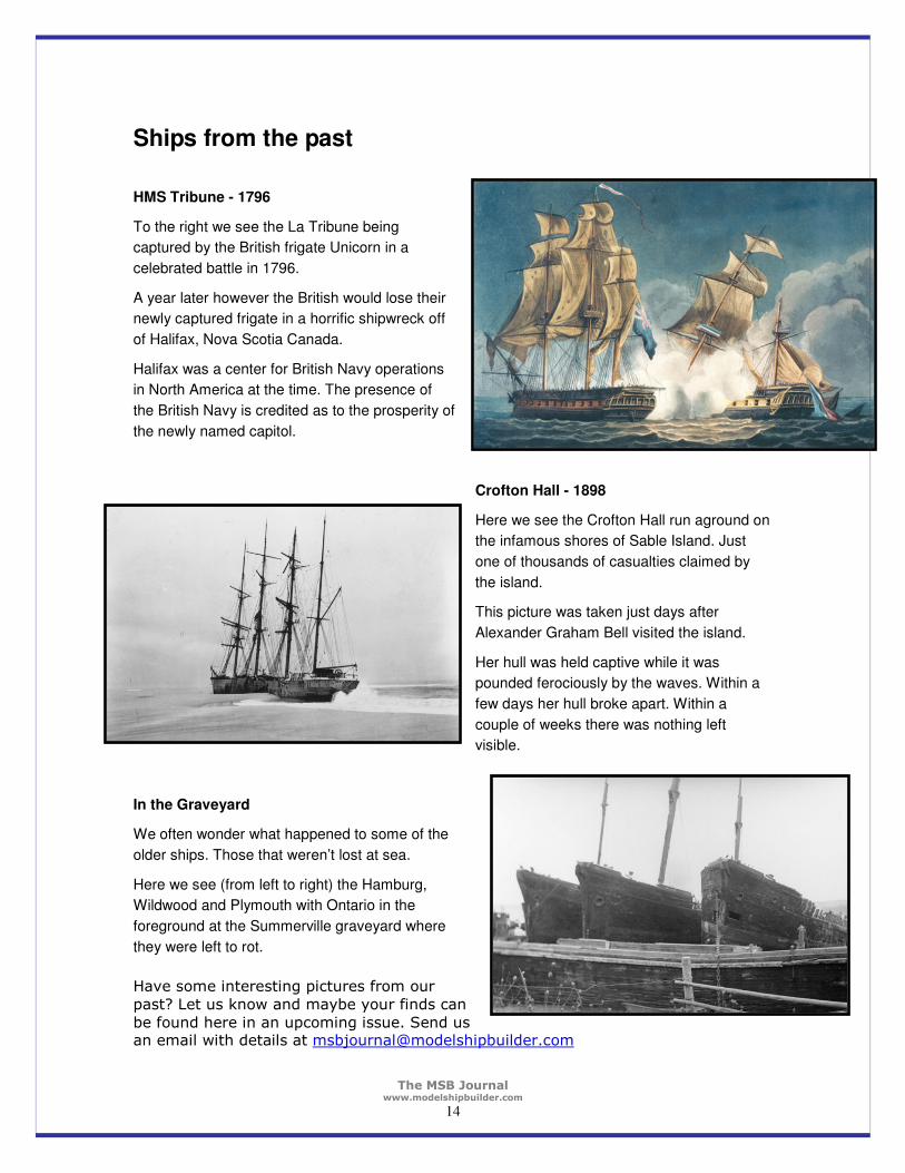
HMS Tribune - 1796
To the right we see the La Tribune being
captured by the British frigate Unicorn in a
celebrated battle in 1796.
A year later however the British would lose their
newly captured frigate in a horrific shipwreck off
of Halifax, Nova Scotia Canada.
Halifax was a center for British Navy operations
in North America at the time. The presence of
the British Navy is credited as to the prosperity of
the newly named capitol.
Crofton Hall - 1898
Here we see the Crofton Hall run aground on
the infamous shores of Sable Island. Just
one of thousands of casualties claimed by
the island.
This picture was taken just days after
Alexander Graham Bell visited the island.
Her hull was held captive while it was
pounded ferociously by the waves. Within a
few days her hull broke apart. Within a
couple of weeks there was nothing left
visible.
In the Graveyard
We often wonder what happened to some of the
older ships. Those that weren’t lost at sea.
Here we see (from left to right) the Hamburg,
Wildwood and Plymouth with Ontario in the
foreground at the Summerville graveyard where
they were left to rot.
Have some interesting pictures from our
past? Let us know and maybe your finds can
be found here in an upcoming issue. Send us an email with details at [email protected]
The MSB Journal www.modelshipbuilder.com
15
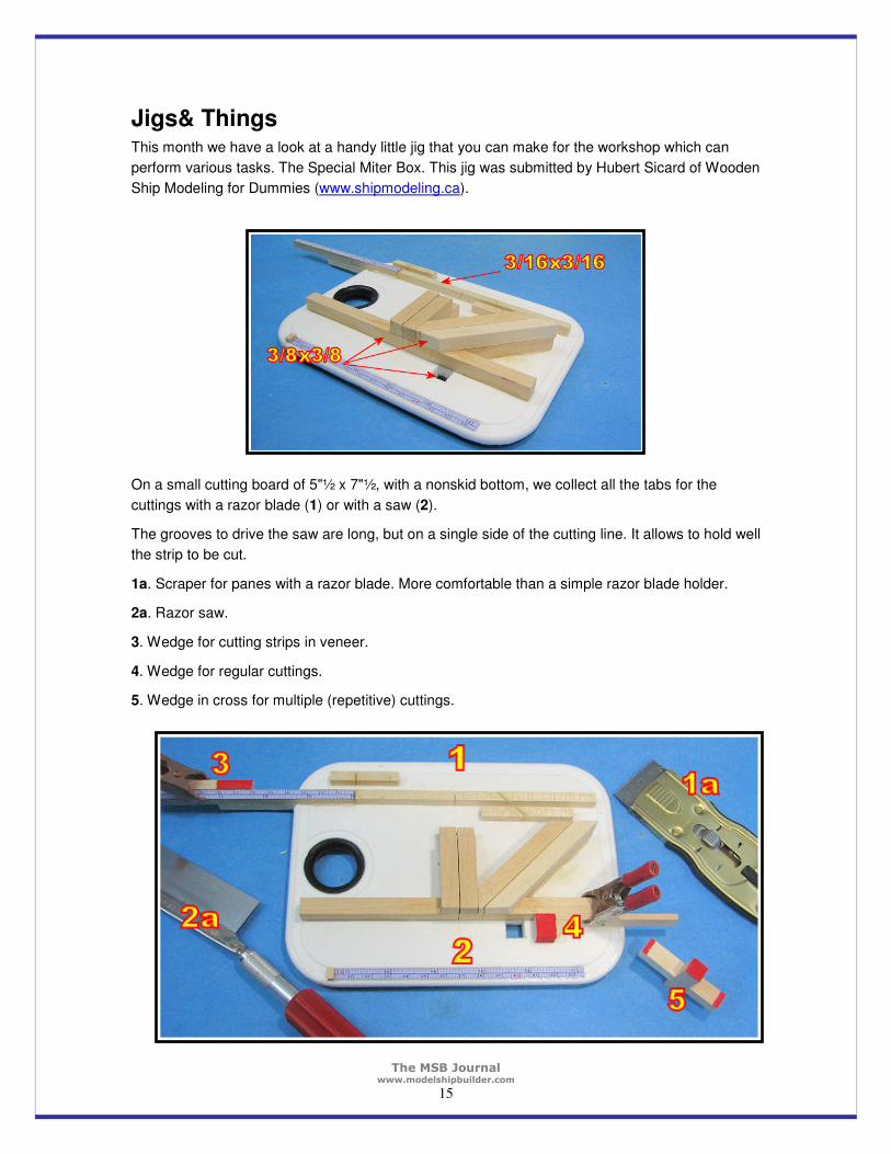
Jigs& Things This month we have a look at a handy little jig that you can make for the workshop which can
perform various tasks. The Special Miter Box. This jig was submitted by Hubert Sicard of Wooden
Ship Modeling for Dummies (www.shipmodeling.ca).
On a small cutting board of 5"½ x 7"½, with a nonskid bottom, we collect all the tabs for the
cuttings with a razor blade (1) or with a saw (2).
The grooves to drive the saw are long, but on a single side of the cutting line. It allows to hold well
the strip to be cut.
1a. Scraper for panes with a razor blade. More comfortable than a simple razor blade holder.
2a. Razor saw.
3. Wedge for cutting strips in veneer.
4. Wedge for regular cuttings.
5. Wedge in cross for multiple (repetitive) cuttings.
The MSB Journal www.modelshipbuilder.com
16
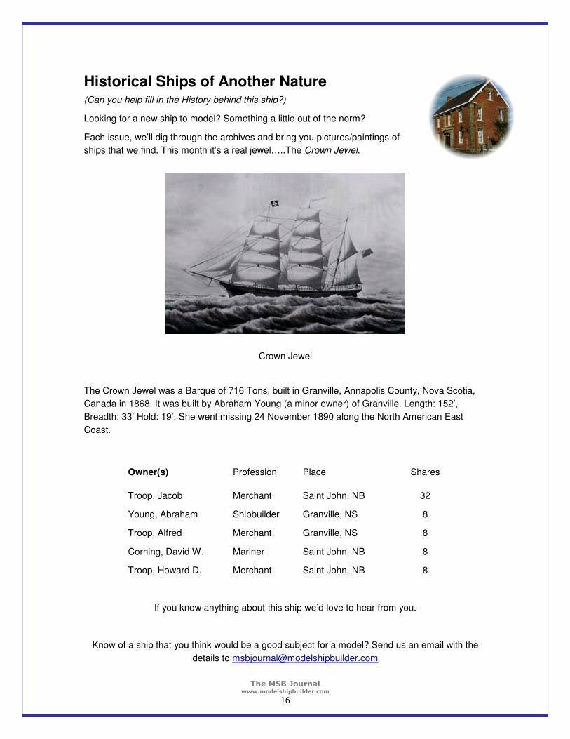
Historical Ships of Another Nature (Can you help fill in the History behind this ship?)
Looking for a new ship to model? Something a little out of the norm?
Each issue, we’ll dig through the archives and bring you pictures/paintings of
ships that we find. This month it’s a real jewel…..The Crown Jewel.
Crown Jewel
The Crown Jewel was a Barque of 716 Tons, built in Granville, Annapolis County, Nova Scotia,
Canada in 1868. It was built by Abraham Young (a minor owner) of Granville. Length: 152’,
Breadth: 33’ Hold: 19’. She went missing 24 November 1890 along the North American East
Coast.
Owner(s) Profession Place Shares
Troop, Jacob Merchant Saint John, NB 32
Young, Abraham Shipbuilder Granville, NS 8
Troop, Alfred Merchant Granville, NS 8
Corning, David W. Mariner Saint John, NB 8
Troop, Howard D. Merchant Saint John, NB 8
If you know anything about this ship we’d love to hear from you.
Know of a ship that you think would be a good subject for a model? Send us an email with the
details to [email protected]
The MSB Journal www.modelshipbuilder.com
17
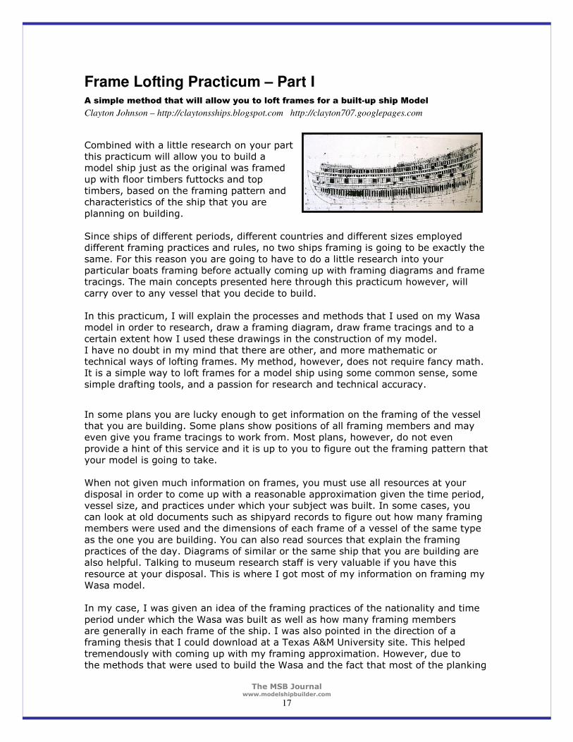
Frame Lofting Practicum – Part I A simple method that will allow you to loft frames for a built-up ship Model
Clayton Johnson – http://claytonsships.blogspot.com http://clayton707.googlepages.com
Combined with a little research on your part this practicum will allow you to build a model ship just as the original was framed
up with floor timbers futtocks and top timbers, based on the framing pattern and characteristics of the ship that you are
planning on building. Since ships of different periods, different countries and different sizes employed different framing practices and rules, no two ships framing is going to be exactly the
same. For this reason you are going to have to do a little research into your particular boats framing before actually coming up with framing diagrams and frame tracings. The main concepts presented here through this practicum however, will
carry over to any vessel that you decide to build. In this practicum, I will explain the processes and methods that I used on my Wasa model in order to research, draw a framing diagram, draw frame tracings and to a
certain extent how I used these drawings in the construction of my model. I have no doubt in my mind that there are other, and more mathematic or technical ways of lofting frames. My method, however, does not require fancy math. It is a simple way to loft frames for a model ship using some common sense, some
simple drafting tools, and a passion for research and technical accuracy.
In some plans you are lucky enough to get information on the framing of the vessel that you are building. Some plans show positions of all framing members and may even give you frame tracings to work from. Most plans, however, do not even
provide a hint of this service and it is up to you to figure out the framing pattern that your model is going to take. When not given much information on frames, you must use all resources at your
disposal in order to come up with a reasonable approximation given the time period, vessel size, and practices under which your subject was built. In some cases, you can look at old documents such as shipyard records to figure out how many framing members were used and the dimensions of each frame of a vessel of the same type
as the one you are building. You can also read sources that explain the framing practices of the day. Diagrams of similar or the same ship that you are building are also helpful. Talking to museum research staff is very valuable if you have this
resource at your disposal. This is where I got most of my information on framing my Wasa model. In my case, I was given an idea of the framing practices of the nationality and time
period under which the Wasa was built as well as how many framing members are generally in each frame of the ship. I was also pointed in the direction of a framing thesis that I could download at a Texas A&M University site. This helped
tremendously with coming up with my framing approximation. However, due to the methods that were used to build the Wasa and the fact that most of the planking

The MSB Journal www.modelshipbuilder.com
18
has never been removed, the ships framing is largely unknown. This forced me to make sacrifices in accuracy but still allowed me to get the framing accurate in a
general way. Getting the framing correct in a general way is what will likely happen with most ships that you attempt to frame, especially ones where documentation is scarce or of
sketchy quality. Even if there is good documentation on the framing of the ship that you are building, who is not to say that plans changed somewhat right before or during construction
and never got recorded on the original plan? This is known to happen with any kind of construction project. Therefore, I believe that using the Wasa as an example in this practicum is fitting.
Many ships that you will model will not have the same degree of complexity and mystery as is contained in the Wasas framing. So, if you can understand what I am going to present in this practicum, you can at least approximate the framing in most
any vessel given that you do a little research with some success. When the below diagram was sent to me, I nearly had a heart attack! It is a
schematic that tried to correlate top timbers with floor timbers that was made at the Wasa museum in the 1980's using a few known locations of timbers. As you can see, it looks pretty messy with no real obvious pattern.
Image Courtesy of Statens Maritima Museer
and drawn by Eva Marie Stolt.
The MSB Journal www.modelshipbuilder.com
19
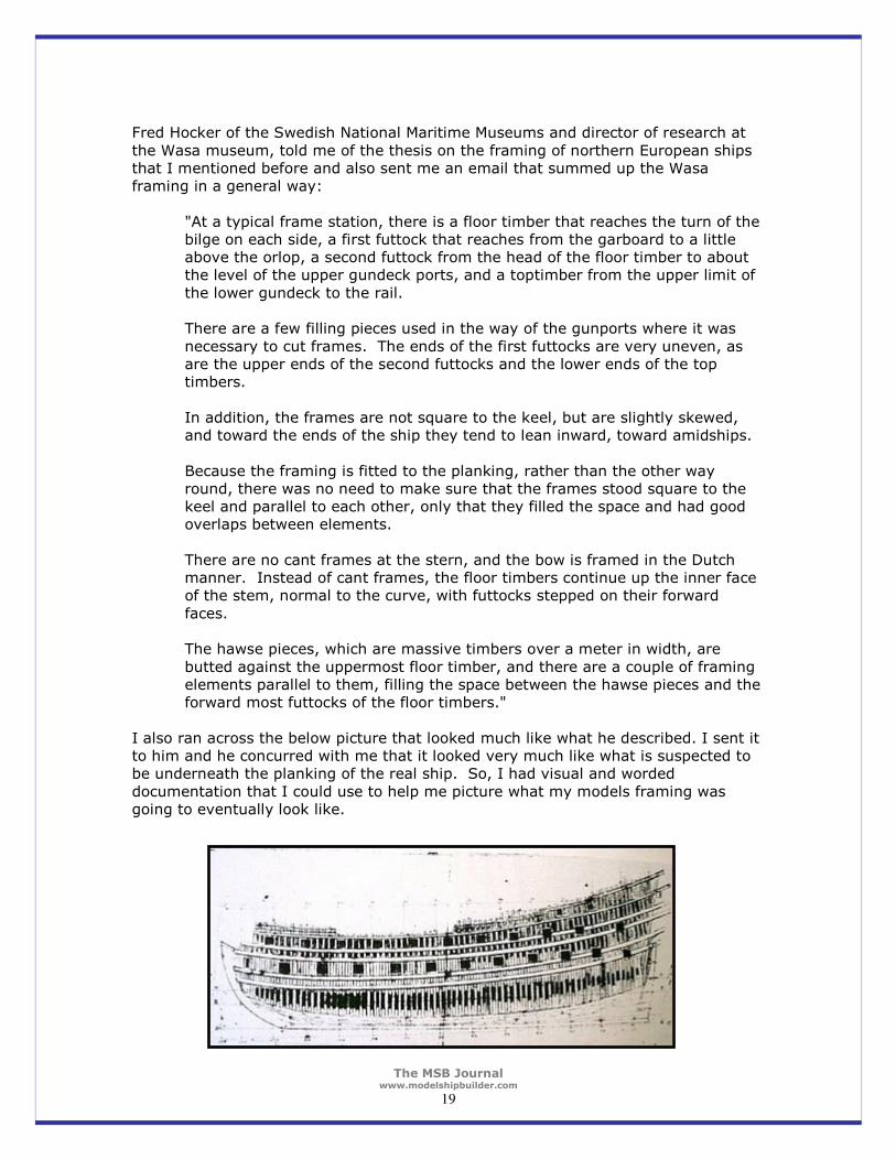
Fred Hocker of the Swedish National Maritime Museums and director of research at
the Wasa museum, told me of the thesis on the framing of northern European ships that I mentioned before and also sent me an email that summed up the Wasa framing in a general way:
"At a typical frame station, there is a floor timber that reaches the turn of the bilge on each side, a first futtock that reaches from the garboard to a little above the orlop, a second futtock from the head of the floor timber to about the level of the upper gundeck ports, and a toptimber from the upper limit of
the lower gundeck to the rail. There are a few filling pieces used in the way of the gunports where it was
necessary to cut frames. The ends of the first futtocks are very uneven, as are the upper ends of the second futtocks and the lower ends of the top timbers.
In addition, the frames are not square to the keel, but are slightly skewed, and toward the ends of the ship they tend to lean inward, toward amidships.
Because the framing is fitted to the planking, rather than the other way round, there was no need to make sure that the frames stood square to the keel and parallel to each other, only that they filled the space and had good overlaps between elements.
There are no cant frames at the stern, and the bow is framed in the Dutch manner. Instead of cant frames, the floor timbers continue up the inner face of the stem, normal to the curve, with futtocks stepped on their forward
faces. The hawse pieces, which are massive timbers over a meter in width, are
butted against the uppermost floor timber, and there are a couple of framing elements parallel to them, filling the space between the hawse pieces and the forward most futtocks of the floor timbers."
I also ran across the below picture that looked much like what he described. I sent it to him and he concurred with me that it looked very much like what is suspected to be underneath the planking of the real ship. So, I had visual and worded
documentation that I could use to help me picture what my models framing was going to eventually look like.
The MSB Journal www.modelshipbuilder.com
20
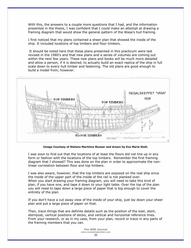
With this, the answers to a couple more questions that I had, and the information presented in the thesis, I was confident that I could make an attempt at drawing a
framing diagram that would show the general pattern of the Wasa's hull framing. I first noticed that my plans contained a sheer plan that showed the inside of the ship. It included locations of top timbers and floor timbers.
It should be noted here that these plans presented in this practicum were last revised in the 1980's and that new plans and a series of volumes are coming out within the next few years. These new plans and books will be much more detailed
and allow a person, if it is desired, to actually build an exact replica of the ship in full scale down to every hull timber and fastening. The old plans are good enough to build a model from, however.
Image Courtesy of Statens Maritima Museer and drawn by Eva Marie Stolt.
I was soon to find out that the locations of at least the floors did not line up in any
form or fashion with the locations of the top timbers. Remember the first framing diagram that I showed? This was done on the plan in order to approximate the non-linear correlation between floor and top timbers.
I was also aware, however, that the top timbers are exposed on the real ship since the inside of the upper part of the inside of the rail is not planked over. When you start drawing your framing diagram, you will need to take this kind of
plan, if you have one, and tape it down to your light table. Over the top of the plan you will need to tape down a large piece of paper that is big enough to cover the entirety of the plan.
If you don't have a cut away view of the inside of your ship, just lay down your sheer plan and put a large piece of paper on that. Then, trace things that are definite details such as the position of the keel, stem,
sternpost, vertical positions of decks, and vertical and horizontal reference lines. From your research, or as in my case, from your plan, record or trace in any parts of the framing members that you can.

The MSB Journal www.modelshipbuilder.com
21
The picture below shows a close up of the forward part of my drawing with reference or station lines, keel, stem, vertical positions of decks, and tentative positions of
floor and top timbers drawn in.
You will also notice that I have a few frames drawn as well. Since the floor timbers and the top timbers didn't correlate in the plan and since the top timbers are exposed on the real ship, I put much more weight on the top timbers and didn't move them at all. Most of the floor timbers that you see drawn in eventually got
erased. Notice that in the above picture and at each frame section, there is a floor timber
going from the garboard to the turn of the bilge (the general vertical position of the turn was taken from the cross section drawings that will be shown later on), a first futtock that goes from the garboard to a little above the orlop deck, a second futtock that goes from the head of the floor timber, or runghead, to the level of the upper
gundeck ports, and a top timber from the upper gundeck to the rail.
This picture above was taken for the sole purpose of sending it in to Fred at the museum to see if I was on the right track.
It turned out that I was a little off when it came to the top timbers. There should have been more overlap between the second futtocks and the top timbers. So I simply made them longer on their lower end. At any rate, however, I followed what Fred of the Wasa museum had told me.
The MSB Journal www.modelshipbuilder.com
22
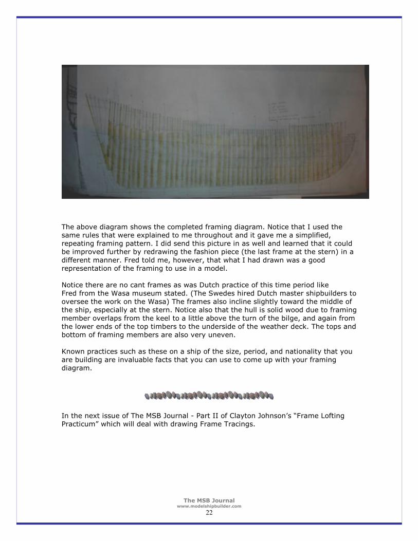
The above diagram shows the completed framing diagram. Notice that I used the same rules that were explained to me throughout and it gave me a simplified, repeating framing pattern. I did send this picture in as well and learned that it could be improved further by redrawing the fashion piece (the last frame at the stern) in a
different manner. Fred told me, however, that what I had drawn was a good representation of the framing to use in a model. Notice there are no cant frames as was Dutch practice of this time period like
Fred from the Wasa museum stated. (The Swedes hired Dutch master shipbuilders to oversee the work on the Wasa) The frames also incline slightly toward the middle of the ship, especially at the stern. Notice also that the hull is solid wood due to framing
member overlaps from the keel to a little above the turn of the bilge, and again from the lower ends of the top timbers to the underside of the weather deck. The tops and bottom of framing members are also very uneven.
Known practices such as these on a ship of the size, period, and nationality that you are building are invaluable facts that you can use to come up with your framing diagram.
In the next issue of The MSB Journal - Part II of Clayton Johnson’s “Frame Lofting Practicum” which will deal with drawing Frame Tracings.
The MSB Journal www.modelshipbuilder.com
23
From the Files of ShipWreckCentral
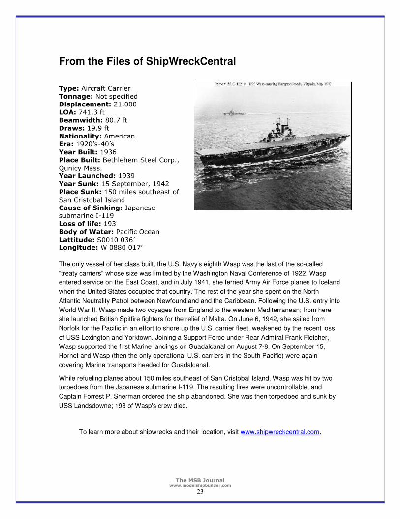
Type: Aircraft Carrier Tonnage: Not specified
Displacement: 21,000 LOA: 741.3 ft Beamwidth: 80.7 ft Draws: 19.9 ft
Nationality: American Era: 1920’s-40’s Year Built: 1936 Place Built: Bethlehem Steel Corp.,
Qunicy Mass. Year Launched: 1939 Year Sunk: 15 September, 1942
Place Sunk: 150 miles southeast of San Cristobal Island Cause of Sinking: Japanese submarine I-119
Loss of life: 193 Body of Water: Pacific Ocean Lattitude: S0010 036’
Longitude: W 0880 017’
The only vessel of her class built, the U.S. Navy's eighth Wasp was the last of the so-called
"treaty carriers" whose size was limited by the Washington Naval Conference of 1922. Wasp
entered service on the East Coast, and in July 1941, she ferried Army Air Force planes to Iceland
when the United States occupied that country. The rest of the year she spent on the North
Atlantic Neutrality Patrol between Newfoundland and the Caribbean. Following the U.S. entry into
World War II, Wasp made two voyages from England to the western Mediterranean; from here
she launched British Spitfire fighters for the relief of Malta. On June 6, 1942, she sailed from
Norfolk for the Pacific in an effort to shore up the U.S. carrier fleet, weakened by the recent loss
of USS Lexington and Yorktown. Joining a Support Force under Rear Admiral Frank Fletcher,
Wasp supported the first Marine landings on Guadalcanal on August 7-8. On September 15,
Hornet and Wasp (then the only operational U.S. carriers in the South Pacific) were again
covering Marine transports headed for Guadalcanal.
While refueling planes about 150 miles southeast of San Cristobal Island, Wasp was hit by two
torpedoes from the Japanese submarine I-119. The resulting fires were uncontrollable, and
Captain Forrest P. Sherman ordered the ship abandoned. She was then torpedoed and sunk by
USS Landsdowne; 193 of Wasp's crew died.
To learn more about shipwrecks and their location, visit www.shipwreckcentral.com.

The MSB Journal www.modelshipbuilder.com
24
Clubs & Organizations with a Web Presence
Each month we’ll display a list of clubs and organizations from around the world which you may
find useful in your modeling. You will find everything from general modeling clubs to websites
where you can pursue research on projects you are working on. You can check at the MSB
website for a more complete list (www.modelshipbuilder.com/resources/links.html).
General Dutch Ship Modelers Association – www.ansf.nl
The Great Schooner Model Society - www.pittelli.com/schooner
Historical Navy Ships Association - www.maritime.org/hnsa-intro.htm
International Naval Research Organization – www.warship.org
National Maritime Historical Society – www.seahistory.org
Nautical Research Guild – www.naut-res-guild.org
Model Yachting Association – Great Britain - www.radiosailing.org.uk
U.S. Vintage Model Yacht Group (Sail) - www.swcp.com/usvmyg
Don’t see a listing you know of or are looking for? Let us know!
Engineering Squares These extremely accurate squares can be of particular value in setting up workshop power equipment – table saws, jointers, or any machine that you require to make precision cuts.
Machined to continental engineering standards (the code used is British Standard 939 Grade B – which means less than 0.001" deviation per inch over the entire length of the blade).
Source: Lee Valley Tools
Handy Tools in the Workshop

The MSB Journal www.modelshipbuilder.com
25
The MSB Journal Classifieds
Have some modeling books, tools, kits that you want to sell? Looking for a place to advertise
them where other modelers will see them?
We are offering this section of The MSB Journal for fellow modelers to do just that. Simply send
us the details of what you have for sale, the price, contact information etc and we’ll fit it into the
next issue.

The MSB Journal www.modelshipbuilder.com
26
Nautical Entertainment
Answers in the next Issue
The MSB Journal www.modelshipbuilder.com
27
Some Nautical Trivia & Fun
The “plow” anchor was designed by Prof. G.I. Taylor of Cambridge University in England. He called it the “CQR”. What do the initials “CQR” stand for?
If you say the three initials fast, it will quickly become evident. For those who can’t…it means “Secure”
What is a Nautical Hammerfer?
Why, driving nautical nails of course!
Where did the term Scuttlebutt come from?
In the days of sail, fresh water was carried in casks or butts. To get the water it was necessary to break it open or scuttle it. To scuttle a butt was to open it for consumption. While taking this water break, the crew often passed ships gossip.
Hence the term Scuttlebutt meaning idle talk or gossip. In the WWII era and sometime thereafter, drinking fountains aboard ship or on shore stations were often called Scuttlebutts.
Why do Lighthouse Keepers keep chickens????
Duh! So they can have eggs with their beacon! LOL….I know…..I just couldn’t help myself!
And finally….
According to tradition, what would you expect to hear from the ship’s bell at midnight
each New Years-Eve?
16 bells. Eight for the year just passed and Eight for the New Year to come. Each, rung
respectively, by the oldest crew member and the youngest.