
The most flexible In-line AOI system€¦ · The most flexible In-line AOI system SJ50 Hardware...
144
The most flexible In-line AOI system SJ50 Hardware Manual
Transcript of The most flexible In-line AOI system€¦ · The most flexible In-line AOI system SJ50 Hardware...

The most flexible In-line AOI system
SJ50Hardware Manual
S J S E R I E S I N S P E C T I O N & M E A S U R E M E N T S Y S T E M S
SJ50 Single Lane Hardware Manual
Revision 1
October’01
Document Part Number 5000-0191
� MV Technology Ltd.
Agilent Technologies,
Silverstone House, Ballymoss Road, Sandyford Industrial Estate, Dublin 18,
Ireland
Phone 353-1-6058320 • Fax 353-1-6058321
All rights reserved. No part of this document may be stored in a retrieval system,
transmitted, or used in any form or by any means, electronic, mechanical,
photocopying, recording or otherwise without the prior permission of the
copyright holder.
MV Technology Ltd. retains the right to modify this document without notice.

© Agilent Technologies HARDWARE MANUAL. ____________________________________________________________________________
Chapter Contents
1.0 Safety ................................................................................. 1 1.1 Machine Safety Standards ...............................2
1.1.1 Machines standards............................................... 2 1.1.2 System Environment ............................................. 2 1.1.3 Machine’s intended use ......................................... 3
1.2 Electrical Safety................................................4 1.2.1 Electrical Enclosure............................................... 4 1.2.2 Emergency Stop Loop ........................................... 5 1.2.3 Earth Bonding........................................................ 5 1.2.4 PC Safety ................................................................ 6
1.3 Physical Safety..................................................7 1.3.1 Protective Guards .................................................. 7 1.3.2 SJ-50 Machine Stability ........................................ 7 1.3.3 Falling Objects ....................................................... 8
1.4 Barcode Laser Safety........................................9
1.5 Explanation of System Warning/Caution Labels........10 2.0 Installation ........................................................................... 13 2.1 Receiving the Machine...................................14
2.1.1 Unpacking the System ......................................... 14 2.1.2 Handling the system ............................................ 14 2.1.3 Opening and Closing of Frame........................... 15
2.2 System Overview .............................................17 2.2.1 Machine Layout ................................................... 17

HARDWARE MANUAL. © Agilent Technologies ____________________________________________________________________________
2.2.1.1 Rear System View.................................................. 18 2.2.1.2 Front System View................................................ 21
2.2.2 Switch plate .......................................................... 22 2.2.3 Front Electrical Enclosure .................................. 23 2.2.4 P.L.C. .................................................................... 25 2.2.5 Conveyor............................................................... 25 2.2.6 System Frame....................................................... 28 2.2.7 Machine Cycle...................................................... 30 2.2.8 Lighting Tower indication .................................. 31
2.3 Machine Assembly..........................................32 2.3.1 Anthro Arm.......................................................... 33
2.3.1.1 Fitting the Anthro Arm........................................... 34 2.3.2 Keyboard, Trackball, Keyboard & Trackball Shelf...... 36
2.3.2.1 Fitting the Keyboard & Trackball Shelf ................. 36 2.3.3 Monitor ................................................................. 36 2.3.4 Connecting Cables ............................................... 37 2.3.5 Lighting Tower .................................................... 38 2.3.6 System Hard Drive .............................................. 39
2.3.6.1 Inserting the System Hard Drive ............................ 39 2.3.7 X-Y Table ............................................................. 41 2.3.8 Camera and Lighting Head ................................ 44
2.4 Machine Installation ......................................45 2.4.1 Height Adjustment............................................... 45 2.4.2 Power up the System ........................................... 46
2.4.2.1 Electrical Power ..................................................... 46 2.4.2.2 Connecting the Mains Cable .................................. 49 2.4.2.3 Pneumatic Power.................................................... 51

© Agilent Technologies HARDWARE MANUAL. ____________________________________________________________________________
2.5 Communications.............................................53 2.5.1 S.M.E.M.A. Communications............................. 53
2.5.1.1 S.M.E.M.A. Connections ....................................... 54 2.5.2 System Connections............................................. 55
2.5.2.1 Network Connections ............................................. 55 2.5.2.2 Serial Connections.................................................. 55
2.6 Machine Operation.........................................56 2.6.1 Powering up Sequences ....................................... 56
2.6.1.1 Powering up the Machine for the first time............ 56 2.6.1.2 Power Up Sequence from ‘Mains Off’ Situation ... 57 2.6.1.2 Power Up Sequence to Restore from ‘E-Stop’
Situation................................................................. 58 2.6.1.3 Maintenance Key Switch........................................ 58
2.6.2 Starting the Application Software...................... 59 2.7 Board Sensors.................................................61
2.7.1 Setting up the Board Sensors.............................. 61 2.8 Conveyor .........................................................62
2.8.1 Using the Easi Tools Application....................... 65 2.8.1.1 Download the Awa122.prg Program..................... 65 2.8.1.2 Arm the Drive Controller Using the Easi Tools
Terminal................................................................. 69 2.8.2 Auto Width Adjust (AWA) ................................. 71
2.8.2.1 Setting Up the Sensors and Flags ........................... 71 2.8.2.2 Test the Inputs and Outputs Using the Terminal
Program ................................................................. 73 2.8.2.3 Check Inputs........................................................... 78 2.8.2.4 Test Outputs ........................................................... 78 2.8.2.5 Test Motors............................................................. 78 2.8.2.6 Test PLC Communication ...................................... 79 2.8.2.7 Check Working of Manual Functionality............... 79 2.8.2.8 Install the AWA GUI ............................................. 80
HARDWARE MANUAL. © Agilent Technologies ____________________________________________________________________________
2.8.3 Using the AWA GUI............................................ 80 2.8.3.1 Advanced Screen.................................................... 82 2.8.3.2 Position Memory after E-Stop................................ 86 2.8.3.3 PLC Interface ......................................................... 86
2.9 PLC Faults......................................................88 3.0 Maintenance.......................................................................... 89 3.1 Introduction ....................................................90
3.2 Electrical Maintenance ..................................91 3.2.1 Weekly .................................................................. 91 3.2.2 Monthly................................................................. 92 3.2.3 Quarterly .............................................................. 92 3.2.4 Yearly.................................................................... 92
3.3 X-Y Table Maintenance .................................95 3.3.1 Weekly .................................................................. 95 3.3.2 Monthly................................................................. 96 3.3.3 Quarterly .............................................................. 97 3.3.4 Yearly.................................................................... 98
3.4 Conveyor Maintenance ..................................99 3.4.1 General Warnings................................................ 99 3.4.2 Weekly ................................................................ 100 3.4.3 Monthly............................................................... 100 3.4.4 Yearly.................................................................. 100 3.4.5 Two Yearly ......................................................... 100
3.5 Pneumatic Maintenance ..............................101 3.5.1 Weekly ................................................................ 101 3.5.2 Monthly............................................................... 101
© Agilent Technologies HARDWARE MANUAL. ____________________________________________________________________________
3.5.3 Yearly.................................................................. 101 3.6 General Maintenance...................................103
3.6.1 Weekly ................................................................ 103 3.6.2 Monthly............................................................... 103
4.0 Troubleshooting Guide ....................................................... 104
4.1 System Power................................................105 4.1.1 Power failure or no Power Response ............... 105 4.1.2 Mains Transformer is not Working................. 105
4.2 Conveyor .......................................................106 4.2.1 Conveyor will not run........................................ 106
4.2.1.1 Conveyor 1 ........................................................... 106 4.2.1.2 Conveyor Will Not Run (no Output from PLC)... 106 4.2.1.3 No Connection to AWA Drive from GUI ............ 107 4.2.1.4 Drives Won’t Move/ Home/ Move to a Given Width.
............................................................................. 108 4.2.1.5 Manual Powered Width Adjust will not Work..... 109 4.2.1.6 Rails not Aligning Properly.................................. 110
4.3 Other Electrical Troubleshooting................111 4.3.1 Lighting Tower will not Operate...................... 111 4.3.2 No 24V Supply ................................................... 111 4.3.3 Safety Relay will not Reset................................ 111 4.3.4 X-Y Table Motor Controller not Operating.... 112 4.3.5 Monitor is not Operating .................................. 112 4.3.6 PC is not Operating ........................................... 113 4.3.7 Camera will not Operate................................... 113
4.4 Pneumatics....................................................114 4.4.1 No Air Supply..................................................... 114

HARDWARE MANUAL. © Agilent Technologies ____________________________________________________________________________
4.4.2 Dump Valve will not Function.......................... 114 4.4.3 Stops will not Engage......................................... 114 4.4.4 Clamp will not Engage ...................................... 114 4.4.5 No purge to X-Y Table ...................................... 115
5.0 System Specifications ......................................................... 116 5.1 SJ-50 Functional Specifications..................117
Software System ....................................................................... 117 Hardware System..................................................................... 117 Supply Facilities ....................................................................... 118 Physical Dimensions................................................................. 118
Appendix I Requirements Listing ........................................119
Appendix II Maintenance Checklists ..................................120

© Agilent Technologies HARDWARE MANUAL. ____________________________________________________________________________
Revision History Revision Nature
of Change
Description Author Date
1.0 First release.
SJ-50 Hardware Manual – Standard Single Lane Conveyor
John Wildes September 2001

SAFETY © Agilent Technologies ____________________________________________________________________________
____________________________________________________________________________
1 5000-0191-01
Chapter 1
1 . 0 Saf e t y
Chapter Contents
1.1 Machine Safety Standards________________________ 2 1.2 Electrical Safety ________________________________ 4 1.3 Physical Safety _________________________________ 7 1.4 Barcode Laser Safety ____________________________ 9
1.5 Explanation of System Warning/Caution Labels ____ 10
Summary
This chapter describes the various safety features that are incorporated into the
machine to provide a safe environment for the operator. The machine is
designed so that during the course of normal operation the user is never required
to work in or have exposure to areas where they could cause harm to themselves
or others.
Safety

© Agilent Technologies SAFETY ____________________________________________________________________________
___________________________________________________________________________
5000-0191-01 2
1.1 Machine Safety Standards
1.1.1 Machines standards The machine has been designed to the following standards. CEI/IEC 1010-1 Safety requirements for electrical equipment for measurement control and laboratory use. UL 3101 Electrical equipment for laboratory use. CE Machinery Directive EC-98/37. See cert for list of relevant standards.
1.1.2 System Environment The Machine is designed to operate under the following conditions: 1 Operating Voltage 100V-120V~ @ 40A Single or two
phase supply 50/60Hz Protection class 1. 2 Operating Voltage 200V-240V~ @ 25A Single or two
phase supply 50/60Hz Protection class 1. 3 Indoor use. 4 Altitude up to 2000m. 5 Temperature 5ºC to 35ºC.

SAFETY © Agilent Technologies ____________________________________________________________________________
____________________________________________________________________________
3 5000-0191-01
6 Maximum Relative Humidity 80% for temperature up to 31ºC decreasing linearly to 50% relative Humidity at 40ºC.
7 Mains Supply Voltage fluctuations not to exceed ±10% of
the nominal voltage. 8 Pollution degree 1 in accordance with IEC 664.
1.1.3 Machine’s intended use In conjunction with the above environmental conditions the machine is used in a surface mount technologies (SMT) production line. The following must be adhered to.
CAUTION!
This machine must only be used with conveyors on both sides either in-line or in off-line operation.

© Agilent Technologies SAFETY ____________________________________________________________________________
___________________________________________________________________________
5000-0191-01 4
1.2 Electrical Safety
1.2.1 Electrical Enclosure Live power and control circuits are situated in various parts of the machine.
• The Mains Transformer is situated at the side of the machine and should not be accessed unless the power to the machine is isolated.
• The Main Control Panel is accessed through the two rear doors, which are electrically interlocked.
• When in the Off position the machine will only have mains voltage on the primary side of the main isolator.
WARNING: LETHAL VOLTAGEDANGEROUS VOLTAGES EXIST IN THIS
EQUIPMENT. ENSURE THAT ALL ELECTRICAL ENCLOSURE COVERS ARE
FITTED AND INTACT BEFORE OPERATING THE EQUIPMENT.

SAFETY © Agilent Technologies ____________________________________________________________________________
____________________________________________________________________________
5 5000-0191-01
1.2.2 Emergency Stop Loop The Emergency Stop (E-Stop) is designed according to the relevant safety standard. The Emergency stop circuit has the following attributes associated with it, it is controlled using a Pilz class IV safety relay.
• During an E-Stop, power is removed from all motors including conveyors and XY Table. It also causes the pneumatic circuits to lose power (except if the Maintenance Key Switch is turned on).
• E-Stop overrides all modes of operation within the SJ-50 machine, with the exception of Maintenance mode.
• The E-Stop of the SJ-50 machine is clearly visible and identifiable. It is a red button at the front right hand side of the machine and is activated by pushing down on it once.
• Raising the front hood has the same effect as pressing the E-Stop.
• When power is removed from the system the E-Stop is activated automatically and must be reset on powering the machine back up.
• On startup No uncontrolled motion can occur.
1.2.3 Earth Bonding All external metal surfaces are mechanically and electrically bonded to the machine earth point. The bonding wire used is identified by its green and yellow insulation.
Note: Never remove or cut these wires. If you find a cut or damaged connection, do not operate the machine and inform a suitable qualified person as soon as possible.

© Agilent Technologies SAFETY ____________________________________________________________________________
___________________________________________________________________________
5000-0191-01 6
1.2.4 PC Safety The PC’s motherboard contains a lithium battery: Maxell 3V. See explanation of warning labels.
Dangerous Voltages may exist in the PC after the electrical supply has been disconnected.
There is a danger of explosion if the battery is incorrectly replaced. Replace only with the same or equivalent type
recommended by the manufacturer.
Dispose of used batteries according to manufacturer instructions.
WARNINGTHIS MACHINE MUST ALWAYS BE
EARTHED WHILE IN USE.
SAFETY © Agilent Technologies ____________________________________________________________________________
____________________________________________________________________________
7 5000-0191-01
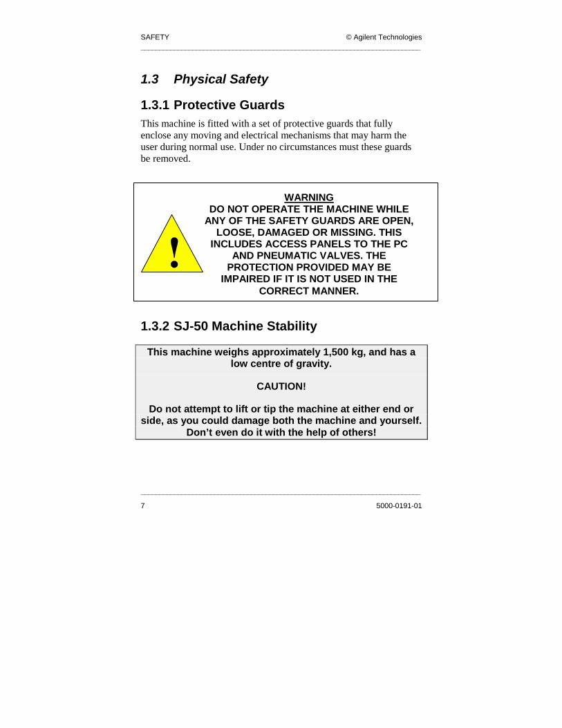
1.3 Physical Safety
1.3.1 Protective Guards This machine is fitted with a set of protective guards that fully enclose any moving and electrical mechanisms that may harm the user during normal use. Under no circumstances must these guards be removed.
1.3.2 SJ-50 Machine Stability
This machine weighs approximately 1,500 kg, and has a low centre of gravity.
CAUTION!
Do not attempt to lift or tip the machine at either end or side, as you could damage both the machine and yourself.
Don’t even do it with the help of others!
WARNINGDO NOT OPERATE THE MACHINE WHILE
ANY OF THE SAFETY GUARDS ARE OPEN, LOOSE, DAMAGED OR MISSING. THIS
INCLUDES ACCESS PANELS TO THE PC AND PNEUMATIC VALVES. THE
PROTECTION PROVIDED MAY BE IMPAIRED IF IT IS NOT USED IN THE
CORRECT MANNER.

© Agilent Technologies SAFETY ____________________________________________________________________________
___________________________________________________________________________
5000-0191-01 8
1.3.3 Falling Objects
Do not store boards, equipment, stencils etc. on top of the machine.

SAFETY © Agilent Technologies ____________________________________________________________________________
____________________________________________________________________________
9 5000-0191-01
1.4 Barcode Laser Safety The Microscan barcode readers use a Class II Semiconductor Laser. It can be dangerous to stare directly into the laser beam.
WARNING: LASER EQUIPMENT
THIS EQUIPMENT CONTAINS CLASS II LASER EQUIPMENT. DO NOT STARE
INTO THE BEAM.

© Agilent Technologies SAFETY ____________________________________________________________________________
___________________________________________________________________________
5000-0191-01 10
1.5 Explanation of System Warning/Caution Labels.
--
Warning electrical danger. Label located on both left and right side panels also on right rear door to indicate High Voltage within.
--
General warning label. Located inside PC at the lithium battery. See Section 1.2.4
The operator must read the manual before operating the machine. Label located on front right side of hood.
Warning to mind your head. Label located on front left and right sides of hood.

SAFETY © Agilent Technologies ____________________________________________________________________________
____________________________________________________________________________
11 5000-0191-01
Moving parts at the conveyor Entry and exit openings (for the Board) at the sides of the machine, which could cause finger and hand Damage.
230 Volts warning labels on the PC, Motor controller, Transformer cover, Top of front electrical box, Mains terminal trunking cover And Mains filter.
--
Warning label hands could be crushed from below. Location on top center of rear panel.
--
Warning label hands could be crushed from right side. Location on rear of the top left side panel.
-
Warning label hands could be crushed from left side. Location on rear of the top right side panel.

© Agilent Technologies SAFETY ____________________________________________________________________________
___________________________________________________________________________
5000-0191-01 12
Warning when maintenance switch is in on position. The pneumatic air pressure is actuated. Using the maintenance GUI the stops and clamps can operate therefore caution pinch points around clamps can cause injury.
Warning of high voltage. Location Transformer cover, mains filter and on mains terminal trunking.

INSTALLATION © Agilent Technologies ____________________________________________________________________________
____________________________________________________________________________
13 5000-0191-01
Chapter 2
2 . 0 In s ta l l a t io n
Chapter Contents
2.1 Receiving the machine .................................................... 14 2.2 System Overview ............................................................. 17 2.3 Machine Assembly........................................................... 32 2.4 Machine installation........................................................ 45 2.5 Communications.............................................................. 53
2.6 Machine Operation ......................................................... 56
2.7 Board Sensors .................................................................. 61
2.8 Conveyor .......................................................................... 62
2.9 PLC Faults ....................................................................... 88
Summary
This chapter provides instructions for setting up and installing the inspection and
measurement systems.
Installation

© Agilent Technologies INSTALLATION. ____________________________________________________________________________
___________________________________________________________________________
5000-0191-01 14
2.1 Receiving the Machine
2.1.1 Unpacking the System The system is shipped in a sturdy wooden protective crate. To remove the system from its crate:
1. Check all the Tip’n’tell Indicators, Shock Sensors etc. 2. Remove the crate top panel by unscrewing the carriage bolts
at the top of the crate using the appropriate socket head driver.
3. Remove the front panel to expose the machine. 4. Remove the two screws securing each foot to the pallet. This
frees the machine for lifting from its crate by use of a forklift. Please read section 2.1.2 ‘Handling the system’, before removing the machine from its crate.
5. Remove the packaged parts from inside the system by removing the lower right panel with a 4mm hexagonal Allen Key. The packaged parts (Lighting Tower, Hard Drive and Documentation) can then be removed and the panel replaced and secured.
6. Remove the Anthro Arm package from inside the machine by opening the hood of the machine (see section 2.1.3 ‘Opening and Closing of Frame’).
2.1.2 Handling the system The system is designed for transportation and handling by either a hydraulic pallet truck or forklift. Note: It is important to note that the lifting device used must be rated to lift and carry a 2 tonne load. The forks of the lifting device should be a minimum of 1.0 metres long with a minimum fork spacing of 0.5 meters wide at the inside of the forks. The system is designed to be lifted from any of its four sides, however, when inserting the forks of the lifting device under the

INSTALLATION © Agilent Technologies ____________________________________________________________________________
____________________________________________________________________________
15 5000-0191-01
machine, care must be taken to ensure that the lower panels are not damaged as a result of poor handling. When lowering the system from an elevated position the lifting device operator must ensure that all sides of the machine are clear from obstructions.
Lower the machine gently into position.
2.1.3 Opening and Closing of Frame 1. The top frame door is opened by lifting the latch handle at
the front of the machine, this unlocks the hood. Details of the hood can be seen in the figure below.
Figure 2.1 Latch and Door Handle
WARNINGThe machine must never be raised while
electrical or pneumatic power is connected.
Door Handle Latch
Handle

© Agilent Technologies INSTALLATION. ____________________________________________________________________________
___________________________________________________________________________
5000-0191-01 16
2. Lift the Hood with the door handle and raise it to the desired
position, the Ratchet Locks hold the door open. 3. To close the door with the door handle, lift the door to its
full extent. This causes the Ratchet Locks to release and the door can be lowered down and latched closed. (The pull handles can be used to bring the door down until the door handle can be reached) See fig 2.2.
Figure 2.2 Closing of frame
Pull handles

INSTALLATION © Agilent Technologies ____________________________________________________________________________
____________________________________________________________________________
17 5000-0191-01
2.2 System Overview The SJ-50 system is constructed from a rigid welded base frame, which gives stability and support to the X-Y Gantry robot and houses the electrical control of the machine.
2.2.1 Machine Layout
• In the machine the Industrial PC and DR600 (Motor Controller) are behind the front access doors, and the Pneumatics Panel is in the rear door.
• The Facilities Panel, mounted in the rear electrical enclosure, provides interconnections for the 2 SMEMA Cables, the Ethernet Cable, and the Serial Port.
• The Electrical Mains Inlet Cable and System Pneumatic Power are supplied through a cut out in the machine base-plate, which is also accessible from the rear Electrical Enclosure.

© Agilent Technologies INSTALLATION. ____________________________________________________________________________
___________________________________________________________________________
5000-0191-01 18
2.2.1.1 Rear System View The main control panel of the machine is housed in the rear electrical enclosure. See detail in figure below.
Figure 2.3 Rear Electrical Enclosure
Paragon Drives
Main Isolator
Solid State Relay
AWA Contactors
PLC Output
MCB
Paragon soft start resistor
Main Contactor
KM1

INSTALLATION © Agilent Technologies ____________________________________________________________________________
____________________________________________________________________________
19 5000-0191-01
The Facilities panel and terminal blocks are to the sides of the main control panel. See details in the figure below.
Figure 2.4 Rear Enclosure Detail
Smema Upstream
Smema Downstream
Network
Facilities Panel
Earth Terminals
Terminals
Single Rail Potentiometers
Serial Port AC Power
PLC Motor Intputs
PLC Misc. Outputs
© Agilent Technologies INSTALLATION. ____________________________________________________________________________
___________________________________________________________________________
5000-0191-01 20
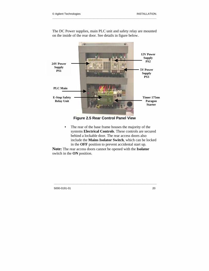
The DC Power supplies, main PLC unit and safety relay are mounted on the inside of the rear door. See details in figure below.
Figure 2.5 Rear Control Panel View
• The rear of the base frame houses the majority of the
systems Electrical Controls. These controls are secured behind a lockable door. The rear access doors also include the Mains Isolator Switch, which can be locked in the OFF position to prevent accidental start up.
Note: The rear access doors cannot be opened with the Isolator switch in the ON position.
E-Stop Safety Relay Unit
Timer 175ms Paragon Starter
24V Power Supply
PS1
12V Power Supply
PS2
5V Power Supply
PS3
PLC Main
INSTALLATION © Agilent Technologies ____________________________________________________________________________
_____________________________________
21
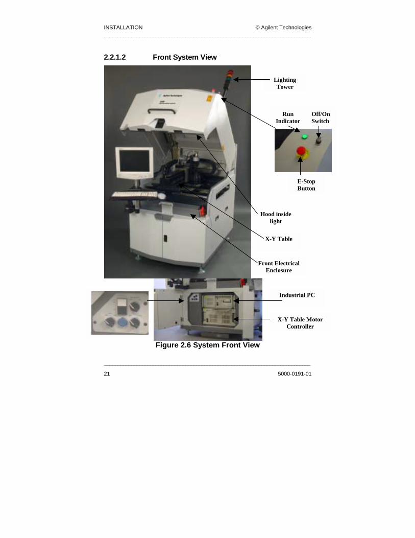
2.2.1.2 Front System View
Figure 2.6 Sys
Lighting Tower
Off/OnSwitch
E-Stop Button
Run Indicator
Hood inside light
_______________________________________
5000-0191-01
tem Front View
X-Y Table
Front Electrical Enclosure
Industrial PC
X-Y Table Motor Controller
© Agilent Technologies INSTALLATION. ____________________________________________________________________________
___________________________________________________________________________
5000-0191-01 22
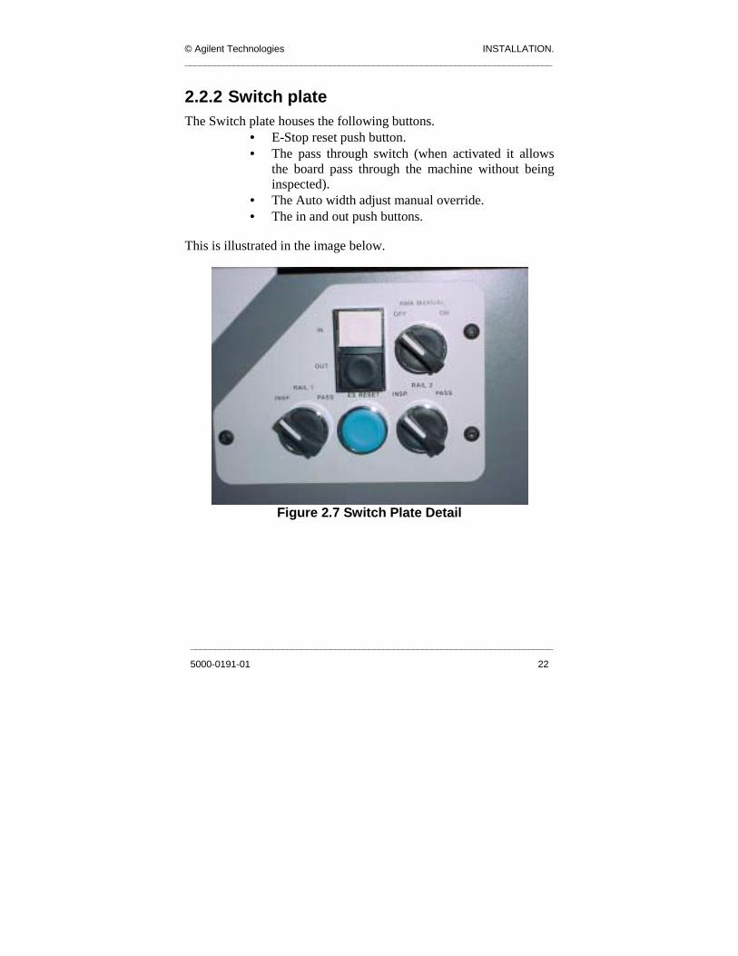
2.2.2 Switch plate The Switch plate houses the following buttons.
• E-Stop reset push button. • The pass through switch (when activated it allows
the board pass through the machine without being inspected).
• The Auto width adjust manual override. • The in and out push buttons.
This is illustrated in the image below.
Figure 2.7 Switch Plate Detail
INSTALLATION © Agilent Technologies ____________________________________________________________________________
________________________________________
23
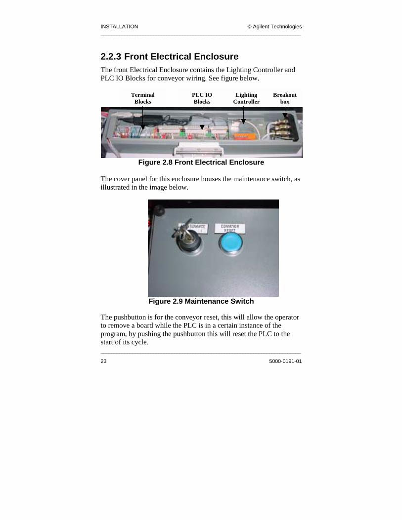
2.2.3 Front Electrical Enclosure The front Electrical Enclosure contains the Lighting Controller and PLC IO Blocks for conveyor wiring. See figure below.
Figure 2.8 Front Electrical Enclosure
The cover panel for this enclosure houses the maintenance switch, as illustrated in the image below.
Figure 2.9 Mainte
The pushbutton is for the conveyor rto remove a board while the PLC is iprogram, by pushing the pushbuttonstart of its cycle.
Breakout box
Lighting Controller
PLC IO Blocks
Terminal Blocks
____________________________________
5000-0191-01
nance Switch
eset, this will allow the operator n a certain instance of the this will reset the PLC to the

© Agilent Technologies INSTALLATION. ____________________________________________________________________________
___________________________________________________________________________
5000-0191-01 24
• The Transformer Guard Panel protects against
unauthorized access to the systems Mains Transformer. See fig 2.10.
Warning
Only trained personnel should remove the Transformer Guard Panel.
Figure 2.10 Transformer Guard Panel
• The Facilities Panel houses the systems communications interfaces. The system’s power is fed in through the base of the machine.
• The final two panels on the system base are the lower-right access panel and the lower-left access panel. These panels need only be removed when access is required to internal system wiring.
Transformer Guard Panel

INSTALLATION © Agilent Technologies ____________________________________________________________________________
____________________________________________________________________________
25 5000-0191-01
2.2.4 P.L.C. The PLC (programmable logic controller) controls the conveyor, monitors the machine sensors and acts accordingly to the application required. It also provides communication to the PC and all the I/O of the machine (for example the lighting tree, SMEMA signals, Air on inputs etc).
2.2.5 Conveyor See also section 2.8 Conveyor. For the purpose of board transfer a conveyor is situated on the X-Y aluminum base along the Y direction of the machine, this allows the boards to be positioned on the conveyor under the inspection envelope. Different types of conveyors are used to adjust to the different demands placed on Agilent by customers. Each type of conveyor uses the same basic materials, which are as follows. On each conveyor or segment is a belt carrying the board along the conveyor. This belt is made from Acrylonitrille-Butadine-Rubber (NBR). A Stepper motor on each rail rotates the belts. These motors are powered in series by a Paragon L50 controller (UL E194158), The stepper motors are in series so that they are synchronized, ensuring both belts run at the same speed. The width of the conveyors can also be adjusted.

© Agilent Technologies INSTALLATION. ____________________________________________________________________________
___________________________________________________________________________
5000-0191-01 26
This is done by stepper motors rotating a screw drive system which move the conveyor along a THK rail in the X direction of the machine. The width adjust is controlled by a Paragon L50i drive. The L50i is an intelligent controller, which can be controlled through software by a RS232 port in the PC allowing the user to move the conveyor to the required width by inputting a value using a graphical user interface. In the event of software failure there is a manual over ride switch, (see fig 2.11) which allow the operator to jog the conveyor in and out.
Figure 2.11 Switch Plate Detail
During an E-Stop condition, the power to the motor is removed for both the conveyor rotation and the auto width adjust, and the 24V power is also removed from the control circuit. This removes all motive power from the conveyors and renders them safe.

INSTALLATION © Agilent Technologies ____________________________________________________________________________
____________________________________________________________________________
27 5000-0191-01
On each conveyor there are two stop cylinders, which activate when a board is entering the inspection envelope of the machine. When the board has stopped in position another group of cylinders are activated to clamp the board to the clamping lips. Each group of cylinders is activated by a solenoid valve situated in the Pneumatic panel on the rear left door of the machine.
© Agilent Technologies INSTALLATION. ____________________________________________________________________________
___________________________________________________________________________
5000-0191-01 28
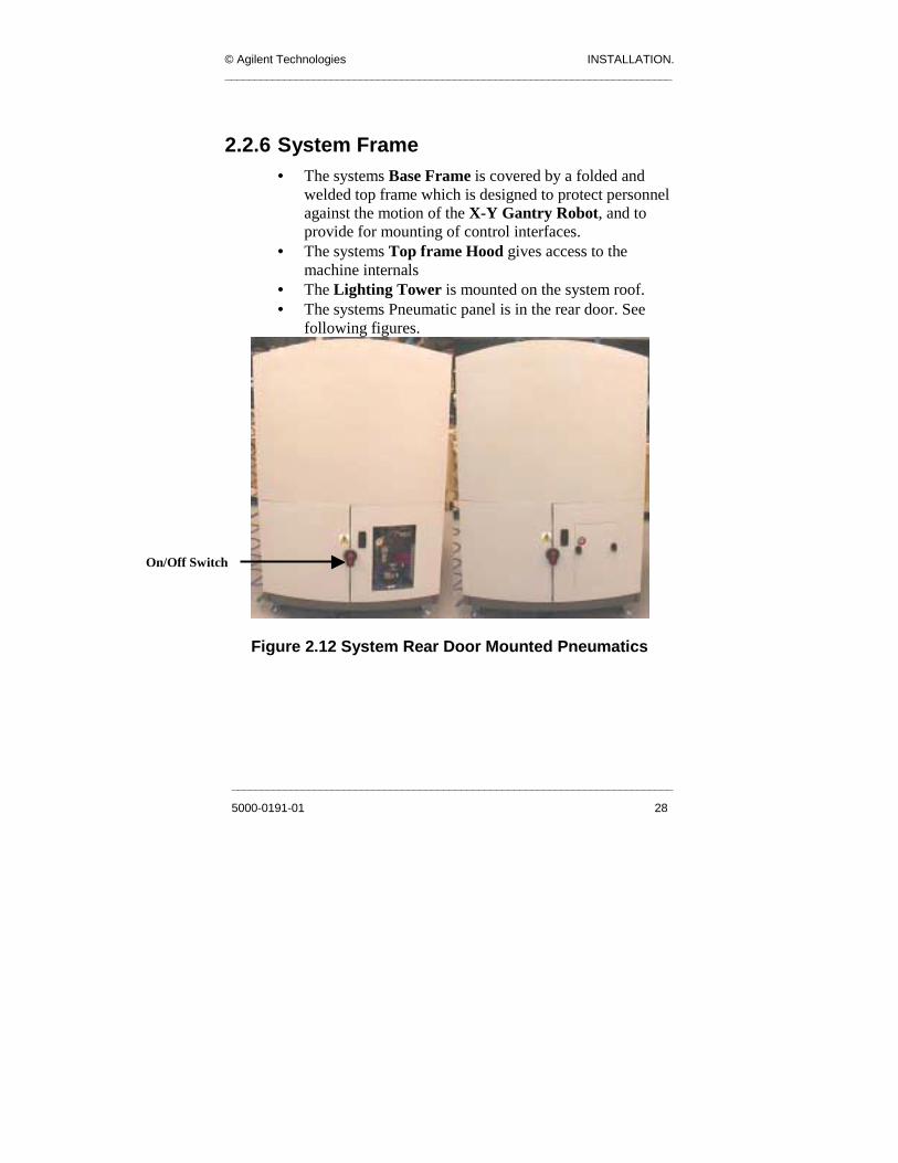
2.2.6 System Frame • The systems Base Frame is covered by a folded and
welded top frame which is designed to protect personnel against the motion of the X-Y Gantry Robot, and to provide for mounting of control interfaces.
• The systems Top frame Hood gives access to the machine internals
• The Lighting Tower is mounted on the system roof. • The systems Pneumatic panel is in the rear door. See
following figures.
Figure 2.12 System Rear Door Mounted Pneumatics
On/Off Switch

INSTALLATION © Agilent Technologies ____________________________________________________________________________
_________
29
Pressure Regulator
Pressure Gauge/Switch
Air Input Tube
Solenoids
Air tubes to X-Y Table
Filter cup
Air tubes to Clamps and
Stops
PLC IO
_________________________________________
Figure 2.13 SJ50 Pneumati
Restr
__________________________
5000-0191-01
cs Panel
ictor

© Agilent Technologies INSTALLATION. ____________________________________________________________________________
___________________________________________________________________________
5000-0191-01 30
2.2.7 Machine Cycle The upstream machine provides a signal to the inspection machine by a machine interface standard called SMEMA.
1. The inspection machine has to give the upstream machine a “Not busy signal”, through the interface connector.
2. When it receives a “Board Available Signal” from the upstream machine, the inspection system transports the board into the system.
3. When the board is inside, the machine disables the “Machine Not Busy” signal to the upstream machine.
4. The board travels along the conveyor over the inspection sensor, it could have passed through other segments of conveyors, depending on the configuration.
5. When the board is detected on the board in place sensor, the pneumatic stops are activated.
6. The board slows down to a stop. 7. The board is clamped in position. 8. The Programmable Logic Controller (PLC) gives a board
present signal to the PC by the RS232 port. 9. The inspection system starts by locating the board reference
points, it does this by activating the relevant lighting rings while moving the X-Y table and using each image acquisition inspecting all the components on the board.
10. When finished and the data has been processed, the PC informs the PLC that the board has passed or failed the inspection.
11. The board is subsequently released, this de-energizes the clamps and the stop pistons,
12. The board drops smoothly onto the conveyor and the conveyor starts running.
13. The board will transfer to the exit sensor. If the inspection machine gets a signal from the downstream conveyor “Not

INSTALLATION © Agilent Technologies ____________________________________________________________________________
____________________________________________________________________________
31 5000-0191-01
busy” via the SMEMA interface connector, it will give a “Board Available” signal either good or bad depending on the inspection result.
14. The board exits the machine and the cycle starts again.
2.2.8 Lighting Tower indication On the top of the machine is a lighting tower this is to indicate to the user different events that occur during the operation of the machine.
• Green Inspecting • Red Board Failed • Amber Waiting for Board • Red+Green+Amber E-Stop On • Amber Flash AWA On • Red Flash PLC Error
© Agilent Technologies INSTALLATION. ____________________________________________________________________________
___________________________________________________________________________
5000-0191-01 32
2.3 Machine Assembly The system is shipped with
• Keyboard, • Trackball, • Keyboard Support Shelf, • Anthro Arm, • Monitor, • Lighting Tower, • System Hard Drive.
They are shipped inside the machine and are wrapped in foam packing to prevent breakage. The following steps are a brief overview of the sequence of events when setting up the machine (more detailed information is provided in subsequent sections):
1. To remove the packages, open the main hood door of the machine and remove the strap holding the foam box in place, the box can now be carefully removed.
2. The Lighting Tower and System Hard Drive are packaged together and stored behind the left hand side base panel.
3. The main Anthro Arm will be on top in the foam box and is the first to be removed and fitted on the machine.
4. Fit the Keyboard Tray. 5. Set up the Monitor. 6. Set up the cabling for the Monitor, Keyboard, and
Trackball (see figure 2.14). 7. Set up the Lighting Tower. 8. Insert the System Hard Drive.

INSTALLATION © Agilent Technologies ____________________________________________________________________________
____________________________________________________________________________
33 5000-0191-01
Figure 2.14 Equipment Packed in Machine
2.3.1 Anthro Arm The anthro arm is used to mount the Monitor, and Keyboard Shelf. The Keyboard can then be placed onto the Keyboard Shelf and you can set up the cabling for the Keyboard, Trackball and Monitor. The Anthro Arm is shown in Figure 2.15.
Anthro Arm
Monitor
Keyboard, Trackball and Cables

© Agilent Technologies INSTALLATION. ____________________________________________________________________________
___________________________________________________________________________
5000-0191-01 34
Figure 2.15 Anthro Arm
2.3.1.1 Fitting the Anthro Arm 1. Remove the four mounting screws. See fig 2.16.
Anthro Arm

INSTALLATION © Agilent Technologies ____________________________________________________________________________
Figure 2.16 Remove the Mounting Screws
2. The Anthro Arm is then placed on the machine and the
holes in the arm mounting plate lined up with the holes in
Monitor signal cable
Location of Mounting
Screws
____________________________________________________________________________
35 5000-0191-01
the base frame. See fig 2.16. 3. Put back in the four mounting screws to secure the Anthro
Arm. 4. Replace the Ø10mm Dowel into the Anthro Arm assembly.

© Agilent Technologies INSTALLATION. ____________________________________________________________________________
___________________________________________________________________________
5000-0191-01 36
2.3.2 Keyboard, Trackball, Keyboard & Trackball Shelf The Keyboard & Trackball Shelf is used to hold the Keyboard and Trackball.
2.3.2.1 Fitting the Keyboard & Trackball Shelf 1. Remove the black rubber cap and the Grommet strips from
the vertical tube on the Anthro Arm. 2. Slide the Keyboard Shelf down the vertical tube and fix in
place by tightening the Quick Release Handle, as illustrated in the figure below:
Figure 2.17 Quick Release Handle
2.3.3 Monitor The system is supplied with one 15-inch Monitor. This monitor is provided with both a Power Cable and a VGA Signal Cable, which are routed through the Anthro Arm and through the front of the machine.
Quick Release Handle

INSTALLATION © Agilent Technologies ____________________________________________________________________________
____________________________________________________________________________
37 5000-0191-01
2.3.4 Connecting Cables The cables that come attached to the Keyboard Tray should be assembled as follows:
1. Run the cables from the machine to the Anthro Arm and fix in place using the cable fixing plate and cable cleats as shown in Fig 2.18
Figure 2.18 Cable Fixing Plate and Cable Sock
2. Feed the cables through the vertical tube. 3. Connect the power and signal cables to the monitor. 4. Connect the Keyboard and Trackball Cables. 5. Connect the Earth Cable.
See fig 2.19 for cable locations.
Cable Fixing Plate Cable Sock
WARNINGUnder no circumstances should the monitor cables be connected while power is applied to the system.
Cable Cleat

© Agilent Technologies INSTALLATION. ____________________________________________________________________________
___________________________________________________________________________
5000-0191-01 38
Figure 2.19 Cable Location
6. Replace the Grommet Strips and the Rubber Cap.
2.3.5 Lighting Tower The system’s Lighting Tower is mounted on the roof of the machine. After unpacking the packaged parts from inside of the machine the Lighting Tower can be fitted on the roof. This is done using the following steps:
1. Remove the long panel from inside the roof of the hood with a 2.5mm Allen Key, revealing a 9-way connector and the hole for the Lighting Tree cable.
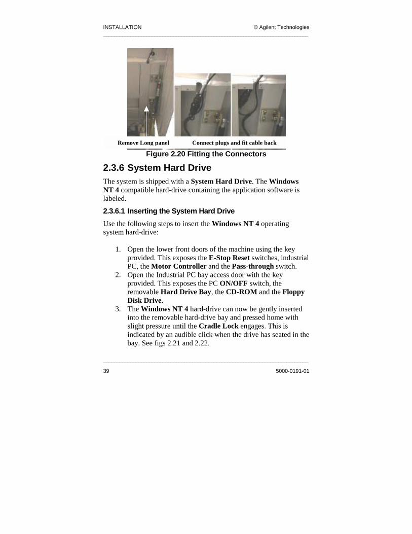
2. Feed the cable back through the mounting hole on the roof and fit the Lighting Tower, as shown in Figure 2.20, with the four screws provided and a 4mm Allen Key.
3. The two 9-way connectors can now be fitted together inside the hood and the long panel replaced to cover them.
INSTALLATION © Agilent Technologies ____________________________________________________________________________
Figure 2.20 Fitting the Connectors
2.3.6 System Hard Drive The system is shipped with a System Hard Drive. The Windows NT 4 compatible hard-drive containing the application software is labeled.
2.3.6.1 Inserting the System Hard Drive Use the following steps to insert the Windows NT 4 operating system hard-drive:
1. Open the lower front doors of the machine using the key provided. This exposes the E-Stop Reset switches, industrial PC, the Motor Controller and the Pass-through switch.
2. ccess door with the key
Remove Long panel Connect plugs and fit cable back
________
39
3.
Open the Industrial PC bay a
____________________________________________________________________
5000-0191-01
provided. This exposes the PC ON/OFF switch, the removable Hard Drive Bay, the CD-ROM and the Floppy Disk Drive. The Windows NT 4 hard-drive can now be gently inserted into the removable hard-drive bay and pressed home with slight pressure until the Cradle Lock engages. This is indicated by an audible click when the drive has seated in the bay. See figs 2.21 and 2.22.

© Agilent Technologies INSTALLATION. ____________________________________________________________________________
___________________________________________________________________________
5000-0191-01 40
Figure 2.21 Hard Drive Not Locked in Hard Drive Bay
4. Turn the cradle-locking key to the lock position:
Figure 2.22 Hard Drive Locked in Hard Drive Bay
5. Remove the Hard Drive Key.

INSTALLATION © Agilent Technologies ____________________________________________________________________________
____________________________________________________________________________
41 5000-0191-01
2.3.7 X-Y Table The Machine is fitted with a X-Y Table linear drive system, it is housed on an aluminum base with dimensions 965mm x 914mm. The X-Y Table consists of a gantry system with:
• An X-axis, and • A Y-axis. See fig 2.23.
Along the long side of the table sits the Y-axis with two aluminum risers on each side. Each riser supports and locates a linear THK rail. A magnet Track sits along the Y-axis at the rear of the machine, (there can be two magnet tracks on some machines). In the magnet track sits the Forcer (Motor) this moves along the Y-axis. The X-axis travels along the Y-axis and is supported by 2 carriages mounted on the linear rails. The X-axis is mounted on a similar aluminum riser which again supports a THK rail and a single magnet track. Each axis has a travel of 500mm.
Attention!A designated person should hold the front and back
panel and hard-drive keys.

© Agilent Technologies INSTALLATION. ____________________________________________________________________________
___________________________________________________________________________
5000-0191-01 42
Figure 2.23 X-Y Table Diagram
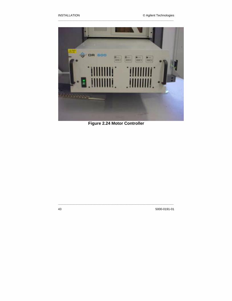
The controllers and the required equipment is enclosed in a DR600 controller chassis (See following figure). Inside the chassis a safety relay supplies mains power to the controllers. When a E-Stop is on or the Gull wing roof is opened power is removed from the controllers.
X-Axis
Y-Axis
INSTALLATION © Agilent Technologies ____________________________________________________________________________
____________________________________________________________________________
43 5000-0191-01
Figure 2.24 Motor Controller

© Agilent Technologies INSTALLATION. ____________________________________________________________________________
___________________________________________________________________________
5000-0191-01 44
2.3.8 Camera and Lighting Head The X-Y table carries the camera and the lighting head. See figure below. The 12V digital camera is mounted over a bank of 8 circular lighting rings that are used to light up the image area at different angles and colours.
Figure 2.25 Camera and Lighting Head
INSTALLATION © Agilent Technologies ____________________________________________________________________________
____________________________________________________________________________
45 5000-0191-01
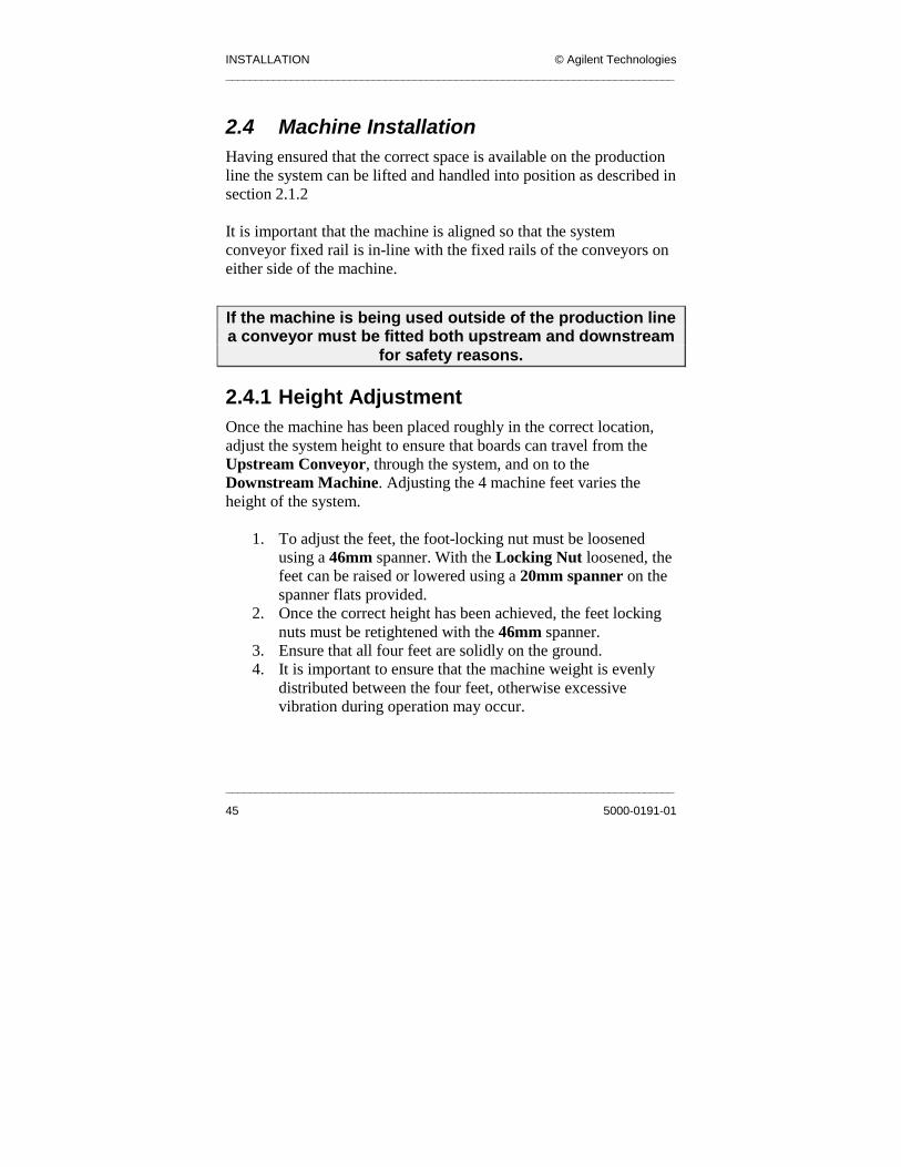
2.4 Machine Installation Having ensured that the correct space is available on the production line the system can be lifted and handled into position as described in section 2.1.2 It is important that the machine is aligned so that the system conveyor fixed rail is in-line with the fixed rails of the conveyors on either side of the machine.
If the machine is being used outside of the production line a conveyor must be fitted both upstream and downstream
for safety reasons.
2.4.1 Height Adjustment Once the machine has been placed roughly in the correct location, adjust the system height to ensure that boards can travel from the Upstream Conveyor, through the system, and on to the Downstream Machine. Adjusting the 4 machine feet varies the height of the system.
1. To adjust the feet, the foot-locking nut must be loosened using a 46mm spanner. With the Locking Nut loosened, the feet can be raised or lowered using a 20mm spanner on the spanner flats provided.
2. Once the correct height has been achieved, the feet locking nuts must be retightened with the 46mm spanner.
3. Ensure that all four feet are solidly on the ground. 4. It is important to ensure that the machine weight is evenly
distributed between the four feet, otherwise excessive vibration during operation may occur.

© Agilent Technologies INSTALLATION. ____________________________________________________________________________
___________________________________________________________________________
5000-0191-01 46
2.4.2 Power up the System
2.4.2.1 Electrical Power All sub-circuits in the system operate at 230V. The system can be set to accept a number of mains voltages (normally 210-240V 25A …100-120V 40A). It achieves this by using a universal transformer. See Figure 2.26. The primary voltage is manipulated to achieve the secondary output voltage of 230V. See Figure 2.27 or the Primary Terminal Wiring set-ups for most common electrical supplies from 100 – 120VAC to 200-240VAC. The user is responsible for the supply and installation of the main power cable to the system. Equipment needs to be installed according to the applicable national wiring code (NEC) and all applicable local regulations. Main incoming protected Earth must be terminated to the base of the Earthing stud. The user must secure N1 (Neutral 1) and L1 (Live 1) to the correct terminals, see section 2.4.2.2.
The link wire must be a minimum cross-sectional area of 6mm² (or 8AWG).
WARNINGAll system sub-circuits are 230VAC. Only
connect equipment rated to this voltage to the system.

INSTALLATION © Agilent Technologies ____________________________________________________________________________
____________________________________________________________________________
47 5000-0191-01
Figure 2.26 Universal Transformer Wiring Diagram
(General)

© Agilent Technologies INSTALLATION. ____________________________________________________________________________
___________________________________________________________________________
5000-0191-01 48
Figure 2.27 Primary Terminal Wiring Set-ups For Most
Common Electrical Supply
The system should be protected by a circuit breaker of not more than the maximum current carrying capacity of
the mains cable. For example this should be of a minimum of 25A for voltages 200-240 or 40A for 100-120V.
INSTALLATION © Agilent Technologies ____________________________________________________________________________
____________________________________________________________________________
49 5000-0191-01
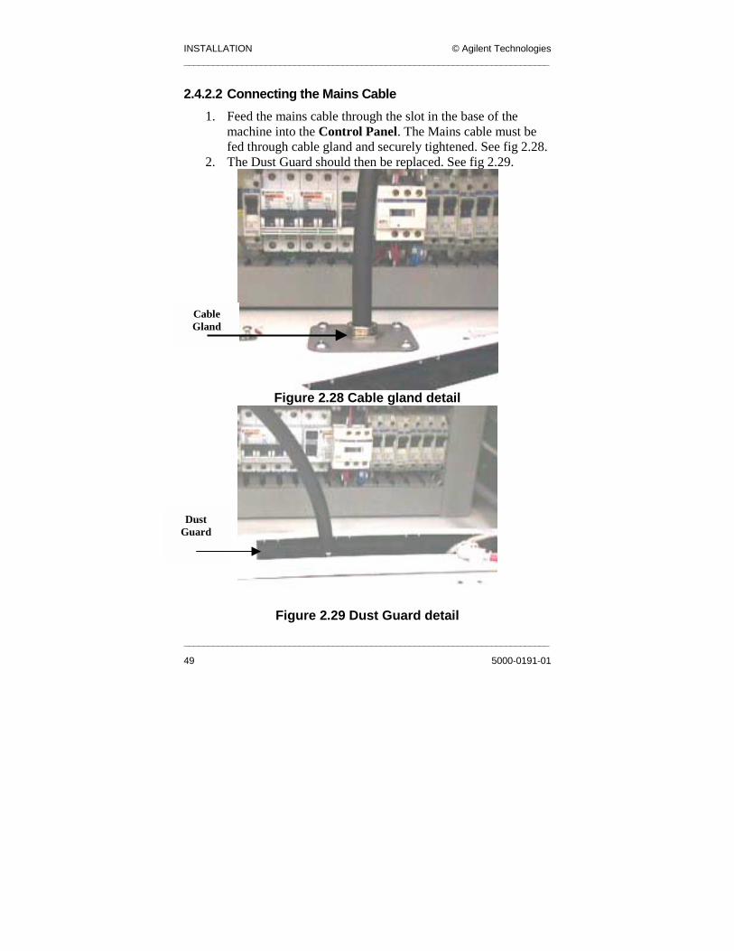
2.4.2.2 Connecting the Mains Cable 1. Feed the mains cable through the slot in the base of the
machine into the Control Panel. The Mains cable must be fed through cable gland and securely tightened. See fig 2.28.
2. The Dust Guard should then be replaced. See fig 2.29.
Figure 2.28 Cable gland detail
Figure 2.29 Dust Guard detail
Cable Gland
Dust Guard

© Agilent Technologies INSTALLATION. ____________________________________________________________________________
___________________________________________________________________________
5000-0191-01 50
Figure 2.30 Connecting the Mains Cable
3. Secure the terminals of each core (Live/Phase1 and Neutral/Phase 2 terminated with Boot Lace Ferrules and the Earth Wire with an Eyelet Ferrule) firmly in place and tidy the cable into the trunking so that it can’t be accidentally pulled. See fig 2.30.
The Earth Wire Eyelet must be placed on the base of the Earth Stud, this means all other Earths will have to be
removed to allow termination.
Live Wire or Phase 1
Neutral Wire or Phase 2
Earth wire
Main Isolator

INSTALLATION © Agilent Technologies ____________________________________________________________________________
____________________________________________________________________________
51 5000-0191-01
Before turning the system on at the Main Isolator, carry out the following steps:
1. Measure the incoming power with a Voltmeter and make
sure Q1 is switched off. 2. Adjust the Transformer as shown in Figure 2.26. It is the
responsibility of the installation personnel to ensure the correct voltage is selected.
3. Measure the voltage at the secondary side of the transformer (terminals L2 & N2) after switching on Q1. Ensure that this is 230V±10% only, if not adjust primary settings accordingly (see Figure 2.27).
4. Measure the voltage between L and Earth on the Main Isolator. This should measure at 230V.
5. Measure between N and Earth on the Main Isolator, this should measure at 0V.
2.4.2.3 Pneumatic Power Pneumatic Power is supplied to the system through the Pneumatic Inlet Port in the rear Electrical Enclosure. This port is a 6mm quick fitting connector and mates with a US standard ¼ inch fitting. The system must be supplied with 5 bar clean filtered air (4 cubic feet/minute).
WARNINGTHIS SYSTEM MUST BE EARTHED BEFORE AND
DURING USE.

© Agilent Technologies INSTALLATION. ____________________________________________________________________________
___________________________________________________________________________
5000-0191-01 52
WARNINGThe System should never be operated without
pneumatic power applied to the system.
INSTALLATION © Agilent Technologies ____________________________________________________________________________
____________________________________________________________________________
53 5000-0191-01
2.5 Communications
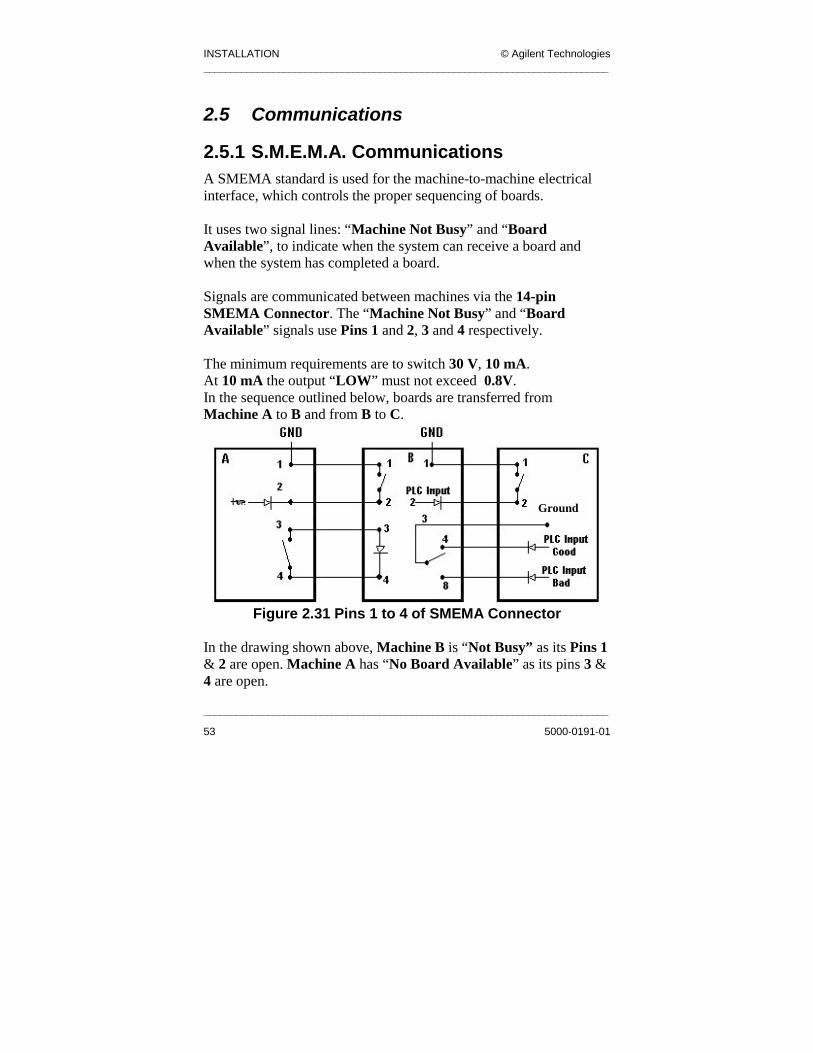
2.5.1 S.M.E.M.A. Communications A SMEMA standard is used for the machine-to-machine electrical interface, which controls the proper sequencing of boards. It uses two signal lines: “Machine Not Busy” and “Board Available”, to indicate when the system can receive a board and when the system has completed a board. Signals are communicated between machines via the 14-pin SMEMA Connector. The “Machine Not Busy” and “Board Available” signals use Pins 1 and 2, 3 and 4 respectively. The minimum requirements are to switch 30 V, 10 mA. At 10 mA the output “LOW” must not exceed 0.8V. In the sequence outlined below, boards are transferred from Machine A to B and from B to C.
Figure 2.31 Pins 1 to 4 of SMEMA Connector
In the drawing shown above, Machine B is “Not Busy” as its Pins 1 & 2 are open. Machine A has “No Board Available” as its pins 3 & 4 are open.
Ground
© Agilent Technologies INSTALLATION. ____________________________________________________________________________
___________________________________________________________________________
5000-0191-01 54
• If Machine A did have a board available for transfer, the
board would trip its Exit Sensor and the machine would close contact between Pins 3 & 4. This would give the signal to Machine B that there is a “Board Available”.
• If Machine B were processing a board, it would close contact between Pins 1 and 2 to give the “Machine Busy” signal to Machine A.
Note: Board transfer only occurs when Machine A has a “Board Available” (contact closed) and Machine B is “Not Busy” (contact closed).
2.5.1.1 S.M.E.M.A. Connections The S.M.E.M.A. interface ports are located inside the rear electrical enclosure of the system. The upstream and downstream connections must be made for the system to function correctly while operating Single or Dual Lane. The system comes equipped with two S.M.E.M.A. Cables for each conveyor line to connect the system to equipment upstream and downstream.
• The Upstream Cable p.n. 2003-0024 must be connected to the SMEMA UP Connector on the Facilities Panel.
• The Downstream Cable p.n. 2003-0025 is connected to the SMEMA DOWN Connector.
These cables need to be routed through the base of the system using the cutout provided. These cables can also be connected in reverse. If an Agilent RS-1 is upstream from the system, connect SLC 28 (S.M.E.M.A cable) downstream.

INSTALLATION © Agilent Technologies ____________________________________________________________________________
____________________________________________________________________________
55 5000-0191-01
2.5.2 System Connections
2.5.2.1 Network Connections An interface connection is located in the rear electrical enclosure to provide for network connectivity of the system. If the networking option has been supplied, please contact your system administrator for details of connecting the system to the network.
2.5.2.2 Serial Connections A serial port connection is provided on the Facilities Panel to allow for the connection of miscellaneous equipment if required (for example Barcode Readers).

© Agilent Technologies INSTALLATION. ____________________________________________________________________________
___________________________________________________________________________
5000-0191-01 56
2.6 Machine Operation
2.6.1 Powering up Sequences
2.6.1.1 Powering up the Machine for the first time
1. Ensure that only trained personnel have connected the electrical power to the system.
2. Measure the voltage of Q1, ensure that this is the rated voltage of the machine.
3. Turn on Q1, measure the voltage between L2 and N2, this is the secondary voltage of the transformer and should always be at 230V AC±10%.
4. Switch on Q2. 5. Switch on all other MCBs. 6. Check the indicator lights on all power supplies (PS1, PS2&
PS3) are on. 7. Verify all circuit breakers are on. 8. Ensure main switch is OFF. 9. Ensure the Motor controller is switched OFF. 10. Ensure that the X-Y Table is free to move over its entire
envelope before continuing. You can manually move it around its enclosure.
11. Ensure that the conveyor is free from obstruction. 12. Ensure the Maintenance switch is in the O position. 13. Ensure that the top frame is fully closed and that the E-Stop
button is depressed before continuing. 14. Close the rear doors, lock them and turn on the machine at
the Main Isolator. 15. Turn the key switch at the front of the machine to the ON
position. 16. Ensure the Run light is illuminated. 17. Ensure the Pass Thru switch is set to Inspect. 18. Turn on the Motor controller unit at the ON switch.

INSTALLATION © Agilent Technologies ____________________________________________________________________________
____________________________________________________________________________
57 5000-0191-01
19. Turn on the Monitor. 20. Release the red E-Stop push button. 21. Turn on the Industrial PC. 22. Reset the Emergency stop by depressing the E-stop reset
button (see figure 2.32).
2.6.1.2 Power Up Sequence from ‘Mains Off’ Situation 1 Turn the Mains Isolator to the ON position when the rear
access doors are locked. 2 Ensure the Maintenance Key Switch is in the O Position 3 Ensure that the X-Y Table is free to move over its entire
envelope before continuing. Remove any tools or equipment that may hinder the table as it moves inside the enclosure.
4 Ensure the Maintenance switch is in the O position. 5 Ensure that the top frame hood is fully closed and the E-
Stop button is pushed in before continuing. 6 Turn the key switch at the front of the machine to the ON
position if not already in this position. The Green run indicator should light.
7 Turn on the Motor Controller unit at the ON switch. 8 Turn on the Monitor. 9 Release the E-Stop push button by pulling it up. 10 Power on the Industrial PC at its ON switch and await the
Log-on prompt. This can take two minutes. 11 Push in the E-Stop Reset button, which is the blue button
located behind the lower front doors on the machine. See fig 2.32.

© Agilent Technologies INSTALLATION. ____________________________________________________________________________
________________________________________
5000-0191-01
Fig 2.32 Location of E-Stop reset button
12 Power on the Industrial PC at its ON switch and await the
Log-on prompt. This can take two minutes.
2.6.1.2 Power Up Sequence to Restore from ‘E-Stop’ Situation
1 Pull out the E-Stop button until it stays up. 2 Press the E-Stop Reset switch.
2.6.1.3 Maintenance Key Switch The Maintenance Key Switch is used f ir pressure on the clamps and stop valves for checking th rs. See next figure.
E-Stop Reset Button
or adjusting ae AWA senso
___________________________________
58

INSTALLATION © Agilent Technologies ____________________________________________________________________________
____________________________________________________________________________
59 5000-0191-01
Figure 2.33 Maintenance Switch and Conveyor Reset
1 The maintenance key switch (fig 2.33) is designed for use by qualified personnel only.
2 It can only be operated when the hood is open (E-stop on). This means that all motors are de-energised.
Caution should be used when activating the Key Switch as misuse may lead to injury.
3 When the Key Switch is in the I position, 24V will be supplied to the pneumatic control panel to allow actuation of the clamps and stop valves and to the Paragon drives to allow checking of the AWA sensors.
4 Actuation of the valves is achieved through the software.
2.6.2 Starting the Application Software After the system is powered up and in Pass Thru mode, the user must log into the main application account in Engineer mode. The following are the username and password for the account: User cpi Password cpi602
Note: The user name and password are case sensitive.
© Agilent Technologies INSTALLATION. ____________________________________________________________________________
___________________________________________________________________________
5000-0191-01 60
For more information refer to the SJ-10 Engineering Mode Manual.
Following log in, the system automatically goes through an initialization procedure. This includes the following:
1. Start X-Windows. 2. Initializes the hardware components such as the X-Y Table,
Lighting Controller communications with the PLC, and the Framestore.
3. The X-Y Table is homed and moved to the Fiducial 1 location for the default PCB. The default PCB is the last PCB that was inspected by the system before it was last shut down.
Note: If the system is being cold started, the user should watch the initialization procedure on screen to ensure that all the sub-systems start successfully.

INSTALLATION © Agilent Technologies ____________________________________________________________________________
____________________________________________________________________________
61 5000-0191-01
2.7 Board Sensors The Entry, Exit and Board in Place Sensors have to be calibrated so that the board triggers the sensors and not the Gantry, which is 20mm above the Conveyor; the sensor is 80mm below the Conveyor, so set the sensor so that it is activated between 80mm and 100mm.
2.7.1 Setting up the Board Sensors The sensors are set up as follows:
1. Place a Fiducial Plate on the Conveyor Rails (not on the Conveyor Belt) over the sensor.
2. Adjust the sensitivity until the sensor just picks up the Fiducial Plate (A red indicator light on the sensor lights when the sensor is activated).
3. Remove the board and move the Gantry and Camera Head over the sensor to ensure that they do not trigger the sensor.
4. Adjust the sensitivity of the sensor by turning the small yellow tuning screw on the sensor. This is illustrated in Figure 2.34:
Figure 2.34 Board Sensor
Red Indicator Light
Tuning Screw

© Agilent Technologies INSTALLATION. ____________________________________________________________________________
___________________________________________________________________________
5000-0191-01 62
2.8 Conveyor This manual is relevant to the following revisions of single lane conveyors:
• 1.0 • 2.0 • 3.0
The conveyor is controlled by the PLC, which gives inputs to a Drive Controller. The Auto Width Adjust feature controls the width of the conveyor. This can be from the GUI, or via a manual selector plate on the machine.There are two Drive Controllers:
• Paragon L50 Controller The Paragon L50 Controller runs the motors, which drives the conveyor. The controller has dip switch settings, which must all be set to OFF.
• Paragon L50i Controller The Paragon L50i Controller is used in the operation of Auto Width Adjust. It has dipswitch settings, set to switch 3 toON, and all others OFF as shown in fig 2.35.

INSTALLATION © Agilent Technologies ____________________________________________________________________________
____________________________________________________________________________
63 5000-0191-01
Figure 2.35 Switch Dipswitch 3 On
These Paragon Drive controllers are illustrated in Figure 2.36. Consult System Electrical drawings for wiring details.
© Agilent Technologies INSTALLATION. ____________________________________________________________________________
___________________________________________________________________________
5000-0191-01 64
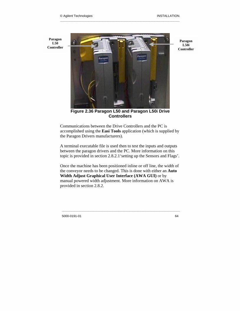
Figure 2.36 Paragon L50 and Paragon L50i Drive
Controllers
Communications between the Drive Controllers and the PC is accomplished using the Easi Tools application (which is supplied by the Paragon Drivers manufacturers). A terminal executable file is used then to test the inputs and outputs between the paragon drivers and the PC. More information on this topic is provided in section 2.8.2.1‘setting up the Sensors and Flags’. Once the machine has been positioned inline or off line, the width of the conveyor needs to be changed. This is done with either an Auto Width Adjust Graphical User Interface (AWA GUI) or by manual powered width adjustment. More information on AWA is provided in section 2.8.2.
Paragon L50
Controller
Paragon L50i
Controller

INSTALLATION © Agilent Technologies ____________________________________________________________________________
____________________________________________________________________________
65 5000-0191-01
2.8.1 Using the Easi Tools Application The Easi Tools application is used to arm the Paragon Drive L50i Controller. This is done using the following steps:
• Download the Awa122.prg file program from: C:\Parker\easitool\examples\Awa122.prg
• Arm the Paragon Drive Controllers using the Easi Tools terminal.
2.8.1.1 Download the Awa122.prg Program
1. Start the Easi Tools application by selecting: Start -> Programs -> Easi Tools Application-> Easi Tools
2. The Easi Tools main toolbar is illustrated in Figure 2.37:
Figure 2.37 Easi Tools Main Toolbar

© Agilent Technologies INSTALLATION. ____________________________________________________________________________
___________________________________________________________________________
5000-0191-01 66
3. Open the latest revision of the Paragon Drive code (Awa122.prg) by:
a. Selecting File -> Open as shown in figure below:
Figure 2.38 File -> Open
b. Select C:\Parker\easitool\examples\Awa122.prg
as shown in Figure 2.39.

INSTALLATION © Agilent Technologies ____________________________________________________________________________
____________________________________________________________________________
67 5000-0191-01
Figure 2.39 Open Awa122.prg
c. Click Ok.
4. Download the program by clicking on the red down arrow as
shown in Figure 2.40.

© Agilent Technologies INSTALLATION. ____________________________________________________________________________
___________________________________________________________________________
5000-0191-01 68
Figure 2.40 Click on the Red Down Arrow
5. Download progress is recorded on a progress bar as the
process runs. This is illustrated in the figure below.
Figure 2.41 Progress Bar
6. When the download is complete, the drive must be armed.
This is done using the Easi Tools Terminal.

INSTALLATION © Agilent Technologies ____________________________________________________________________________
____________________________________________________________________________
69 5000-0191-01
2.8.1.2 Arm the Drive Controller Using the Easi Tools Terminal
1. To open a Terminal session, click the computer terminal icon on the Easi Tools main toolbar as shown in Figure 2.42:
Figure 2.42 Click the Terminal Icon
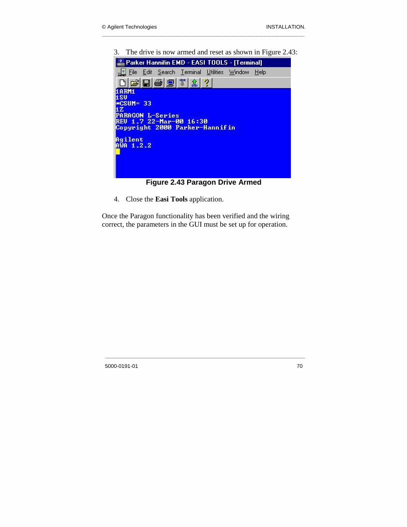
2. To arm the drive, type the following commands in the
Terminal:
1ARM1 <Enter> 1SV <Enter> 1Z <Enter>
Note: The commands are case-sensitive, in this case all letters are capitals.
© Agilent Technologies INSTALLATION. ____________________________________________________________________________
___________________________________________________________________________
5000-0191-01 70
3. The drive is now armed and reset as shown in Figure 2.43:
Figure 2.43 Paragon Drive Armed
4. Close the Easi Tools application.
Once the Paragon functionality has been verified and the wiring correct, the parameters in the GUI must be set up for operation.

INSTALLATION © Agilent Technologies ____________________________________________________________________________
____________________________________________________________________________
71 5000-0191-01
2.8.2 Auto Width Adjust (AWA) The principle of AWA is that the Operator can adjust the conveyor width without opening the front door of the machine. The Conveyor has 3 sensors on it for Automatic Width Adjust (AWA) control. The sensors are for minimum width, maximum width, and alignment. The width is powered by two DC Stepper Motors, which are powered together to be used when moving to the required width. The right DC Stepper Motor runs on its own so that the conveyor can align itself, i.e. the entry width is the same as the exit width.
2.8.2.1 Setting Up the Sensors and Flags The AWA sensors used to keep the board within its bounds are the
• Left Minimum Width sensor. (Left Min). • Right Minimum Width sensor. (Right Min). • Left Maximum Width sensor. (Left Max).
Flags mounted on the rails trigger these sensors. The flags and sensors are illustrated in Figure 2.44.

© Agilent Technologies INSTALLATION. ____________________________________________________________________________
___________________________________________________________________________
5000-0191-01 72
Figure 2.44 AWA Flags and Sensors
The sensors are installed so that each sensor is triggered when the rails are a specific distance apart. This is not the same for all type of conveyors:
• For revision 1.0 and 2.0 conveyors, the rails should be able to move in to 65mm width or less.
• For revision 3.0 conveyors, the rails have to be able to move in to 54mm width or less.
Left Max Sensor Left Flag Left Min
Sensor
Right Min Sensor

INSTALLATION © Agilent Technologies ____________________________________________________________________________
____________________________________________________________________________
73 5000-0191-01
This is done for the Left Min and Right Min sensor:
• The Left Min sensor is installed so that it triggers when the rails can move in to 65mm or less(or 54 mm for the 3.0 conveyor) apart.
• The Left Max is installed so that it triggers when the rails are a distance of approximately 490mm (approximately 2mm less than the maximum travel distance).
Note: The minimum width between the rails can be reduced to 50mm for the 3.0 conveyors by reducing the edge clearance by 2mm on both the adjustable and fixed rail
2.8.2.2 Test the Inputs and Outputs Using the Terminal Program To test the inputs and corresponding outputs, use the following steps:
1. Open the Terminal executable C:\AutoWidthAdjust\terminal.exe.
2. Go to file, Open and open the file C:\AutoWidthAdjust\AWATest.trm provided with the AutoWidthAdjustv2.1.1
3. Check that the correct comm port (Connector) and Baud Rate (9600) are selected.
This is done by clicking Settings -> Communications. The following menu is displayed in Figure 2.45.

© Agilent Technologies INSTALLATION. ____________________________________________________________________________
___________________________________________________________________________
5000-0191-01 74
Figure 2.45 Terminal Communications settings
4. Open the machine hood and switch the Maintenance switch
ON. This causes the Paragon Drive to automatically reset, giving a message similar to the one in fig 2.46. The response from the drive will indicate a drive fault by the text “Drive Flt”. This is due to 55V not being connected to the drive. This is OK!
INSTALLATION © Agilent Technologies ____________________________________________________________________________
____________________________________________________________________________
75 5000-0191-01
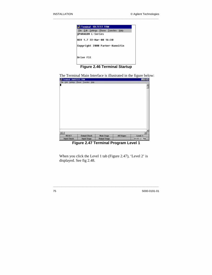
Figure 2.46 Terminal Startup
The Terminal Main Interface is illustrated in the figure below:
Figure 2.47 Terminal Program Level 1
When you click the Level 1 tab (Figure 2.47), ‘Level 2’ is displayed. See fig 2.48.

© Agilent Technologies INSTALLATION. ____________________________________________________________________________
___________________________________________________________________________
5000-0191-01 76
Figure 2.48 Terminal Program Level 2
5. The program awatest.trm has pre-encoded commands to
make debugging the conveyor easier. The tabs in this terminal program are:
• RESET
Resets the drive - This generally causes the drive to output some startup text to the screen when in communication with the PC.
• Input Check Checks the Input state of the drive. Each bit (1 or 0) corresponds to that input being ON or OFF respectively.
• Output Check: Checks the output state of the drive. Each bit (1 or 0) corresponds to that input being ON or OFF respectively.
• Input Stage: Sets Output 5 ON so that the Input Stage can be controlled alone. This also enables the sensors for the input stage to be read by the drive.

INSTALLATION © Agilent Technologies ____________________________________________________________________________
____________________________________________________________________________
77 5000-0191-01
• Main Stage:
Sets Output 4 ON so that the Main Stage can be controlled alone. This also enables the sensors for the main stage to be read by the drive.
• Output Stage: Sets Output 7 ON so that the Output Stage can be controlled alone. This also enables the sensors for the output stage to be read by the drive.
• All Stages: Sets Output 8 ON so that the all three stages can be controlled together. This also enables the sensors for the main stage to be read by the drive. These are the only sensors read when All Stages is set.
• Level 1: Makes the next set of buttons visible on the screen. These buttons include the following:
• Move Out:
Moves the conveyor out 5mm (for which ever stage is enabled).
• Move In: Moves the conveyor in 5mm (for which ever stage is enabled).
• Busy On: Sets output 6 ON. This connects to the PLC and tells the PLC that the conveyor wants to move.
• Busy Off: Switches OFF the Busy On signal.
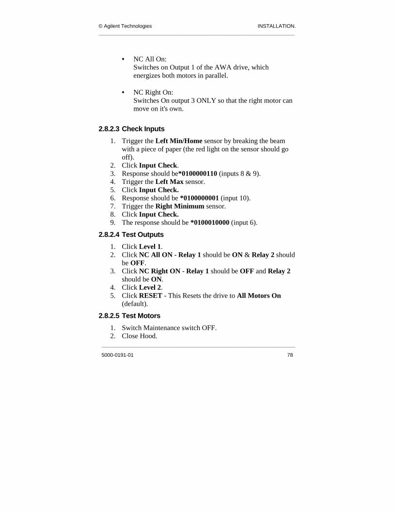
© Agilent Technologies INSTALLATION. ____________________________________________________________________________
___________________________________________________________________________
5000-0191-01 78
• NC All On:
Switches on Output 1 of the AWA drive, which energizes both motors in parallel.
• NC Right On: Switches On output 3 ONLY so that the right motor can move on it's own.
2.8.2.3 Check Inputs 1. Trigger the Left Min/Home sensor by breaking the beam
with a piece of paper (the red light on the sensor should go off).
2. Click Input Check. 3. Response should be*0100000110 (inputs 8 & 9). 4. Trigger the Left Max sensor. 5. Click Input Check. 6. Response should be *0100000001 (input 10). 7. Trigger the Right Minimum sensor. 8. Click Input Check. 9. The response should be *0100010000 (input 6).
2.8.2.4 Test Outputs 1. Click Level 1. 2. Click NC All ON - Relay 1 should be ON & Relay 2 should
be OFF. 3. Click NC Right ON - Relay 1 should be OFF and Relay 2
should be ON. 4. Click Level 2. 5. Click RESET - This Resets the drive to All Motors On
(default).
2.8.2.5 Test Motors 1. Switch Maintenance switch OFF. 2. Close Hood.

INSTALLATION © Agilent Technologies ____________________________________________________________________________
____________________________________________________________________________
79 5000-0191-01
3. Reset E-Stop. 4. Click Level 1. 5. Click Move Out - both Rails should move out together
(5mm). 6. Click Move In - both rails should move in together (5mm). 7. Click NC Right On. 8. Click Move Out - right side ONLY should move out. 9. Click Move In - right side ONLY should move in. 10. Click Level 2. 11. Click RESET.
2.8.2.6 Test PLC Communication 1. Click Level 1 tab. 2. Click the Busy ON tab. The conveyor should run for 2
seconds and then switch OFF. 3. Click the Busy OFF tab. 4. Click the Level 2 tab. 5. Trigger the input sensor so that the conveyor starts to move. 6. Click the Input Check tab. The response should be
*0100000000.
2.8.2.7 Check Working of Manual Functionality 1. Switch the AWA manual Switchplate to the ON position.
This should cause the drive to output MAN to the screen. 2. Press the manual IN button. This should cause the rail to
move in and output NegMan to the screen. 3. Check that the rail moves in and stops automatically at the
Home sensor. 4. Press the manual OUT button. This should cause the rail to
move out and output PosMan to the screen. 5. Check that the rail moves out and stops automatically at the
Left Maximum sensor. 6. Set the manual AWA switch back to OFF.

© Agilent Technologies INSTALLATION. ____________________________________________________________________________
___________________________________________________________________________
5000-0191-01 80
2.8.2.8 Install the AWA GUI Use the following procedure to install the AWA GUI:
1. Open the file AutoWidthAdjustv2.1.1.zip file on the CD provided with the system.
2. Click Install. 3. Follow the on-screen options.
2.8.3 Using the AWA GUI Before using the AWA GUI the conveyor rails must be set up as follows.
1. Manually align the rails with vernier calipers so that they are parallel.
2. When the GUI is fully installed, go to: Start -> Programs ->SJ-50 GUI -> AutoWidthAdjustv2.1.1
When the GUI starts, it attempts to communicate with the drive. If this attempt is unsuccessful, go to the Advanced screen; change the Comm port setting to 3, and make sure that the Baud is set to 9600.
3. Click the Advanced tab, the password to access the
Advanced menu is autowidth and it is case-sensitive. 4. Enter into the parameters Home Width Main Stage and
Min Width Position, the distance at which the Left Min sensor is triggered. Enter into the Max Width parameter the distance at which the Left Max sensor is triggered.
5. Ensure that Speed is set at 2, and Acc/Dec is set to 300. 6. Run calibration. 7. When calibration is complete, click OK on the Advanced
screen. 8. Home the conveyor. 9. Run the conveyor to 100mm – check the width with calipers. 10. Run the conveyor to 150mm – check the width with calipers.
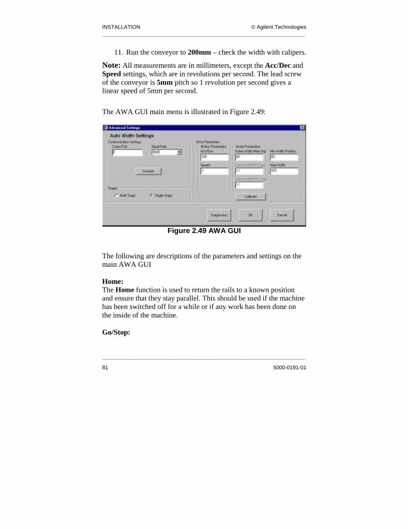
INSTALLATION © Agilent Technologies ____________________________________________________________________________
____________________________________________________________________________
81 5000-0191-01
11. Run the conveyor to 200mm – check the width with calipers.
Note: All measurements are in millimeters, except the Acc/Dec and Speed settings, which are in revolutions per second. The lead screw of the conveyor is 5mm pitch so 1 revolution per second gives a linear speed of 5mm per second.
The AWA GUI main menu is illustrated in Figure 2.49:
Figure 2.49 AWA GUI
The following are descriptions of the parameters and settings on the main AWA GUI Home: The Home function is used to return the rails to a known position and ensure that they stay parallel. This should be used if the machine has been switched off for a while or if any work has been done on the inside of the machine. Go/Stop:

© Agilent Technologies INSTALLATION. ____________________________________________________________________________
___________________________________________________________________________
5000-0191-01 82
The Go button moves the conveyor to the required width, and the Stop button stops the motion if the conveyor is in the middle of a move. These functions are disabled while the machine is homing. Jog: The Jog functionality allows you to jog the rails in or out within the bounds of the sensors. To use this functionality, tick the checkbox Jog Enable when required, and deselect it when finished. No other functions are available when Jog is enabled.
1. Click on the Jog In button to move the conveyor in. Release the button to stop.
2. Click on the Jog Out button to move the conveyor out. Release the button to stop.
3. If the conveyor triggers the sensor while moving, the conveyor stops and displays a warning message. Click OK and the conveyor will move off the sensors.
Status: The Status gives the following status displays:
• AXIS NOT HOMED • AXIS HOMING • AXIS HOMED • AXIS MOVING TO INPUT WIDTH • AXIS STOPPED
Enter Width: This is where you enter the desired width for the conveyor to move. Either press <Enter> on the keyboard or press Go on the GUI.
2.8.3.1 Advanced Screen The Advanced settings screen (See fig 2.50) is where the parameters of the drive are set. It is password protected. The password is autowidth.

INSTALLATION © Agilent Technologies ____________________________________________________________________________
____________________________________________________________________________
83 5000-0191-01
If the Advanced parameters are not accurately recorded and set, the AWA will not work properly or with the desired accuracy.
Figure 2.50 AWA Advanced Settings
Communication Settings Comm Port: This is the communications port on the PC through which the PC communicates with the AWA drive. The AWA setting is 3. Baud Rate: Standard is 9600 bps.

© Agilent Technologies INSTALLATION. ____________________________________________________________________________
___________________________________________________________________________
5000-0191-01 84
Connect: When the Baud Rate and Comm Port have been set, clicking Connect will set the GUI to use these new communications settings. Motion Parameters Acc/Dec: This is the variable, which defines the acceleration and deceleration of the drive when stopping and starting. It is measured in revolutions of the lead screw per second. Speed: This is the rotational speed of the AWA motor. This is limited to a maximum of 5. Attempts to enter a higher value will give a warning and then set the value at 5. Stages Set this to Single Stage for single lane conveyors. Home Parameters Home Width Main Stage: This is the width of the conveyor when the Left Min sensor is triggered. This is a reference point for the AWA Conveyor. Home Width IP Stage: Not used for this release. Home Width OP Stage: Not used for this release. Min Width Position: This is to be set to the same value as Home Width Main Stage. Max Width: This is the width of the conveyor when the Left Max sensor is triggered.

INSTALLATION © Agilent Technologies ____________________________________________________________________________
____________________________________________________________________________
85 5000-0191-01
Note: The values for the conveyor widths may be displayed in microns, as a result of a previous version of the AWA GUI being used. These should be changed to the proper units of millimeters.
Calibrate: The Calibrate functionality is used to determine if there is any offset in the positioning of the Left Min and Right Min sensors. This value is used to maintain parallelism between the rails when they are homed. This is done using the following procedure:
1. Align rails, making sure they are parallel using Vernier Calipers.
2. Close Hood. 3. Reset E-Stop. 4. Click the Calibrate button. 5. The conveyor moves and determines the offset between the
Left Min and Right Min sensors. 6. If calibration is completed successfully the following
message is displayed:
Figure 2.51 Calibration Complete Message
7. If the sensors are offset by more than 10 mm, calibration
fails and the following message is displayed:

© Agilent Technologies INSTALLATION. ____________________________________________________________________________
___________________________________________________________________________
5000-0191-01 86
Figure 2.52 Calibration Failed Message
8. In this instance, align the sensors more accurately using
Allen keys, and repeat the process. 9. The ideal value reported for the offset is 0. The closer to this
value the better.
2.8.3.2 Position Memory after E-Stop The AWA GUI remembers its last position and continually writes this to the file: C:\AutoWidthAdjust\AWApos.txt. The position is maintained in the event of an Emergency Stop, or if the GUI is shut down. This means that the AWA does not have to be HOMED after each E-Stop, however it should be HOMED after any work on the internal mechanism of the machine, or if it has not been used in a long time.
2.8.3.3 PLC Interface The AWA GUI interfaces on a basic level with the PLC to provide the following functionality:
• Conveyor width does not change while conveyor is running. • Conveyor width does not change while there is a board in the
machine. • Conveyor does not run while the AWA is in motion.

INSTALLATION © Agilent Technologies ____________________________________________________________________________
____________________________________________________________________________
87 5000-0191-01
If a move is attempted while the conveyor is busy, the following message appears:
Figure 2.53 Conveyor is Busy Message
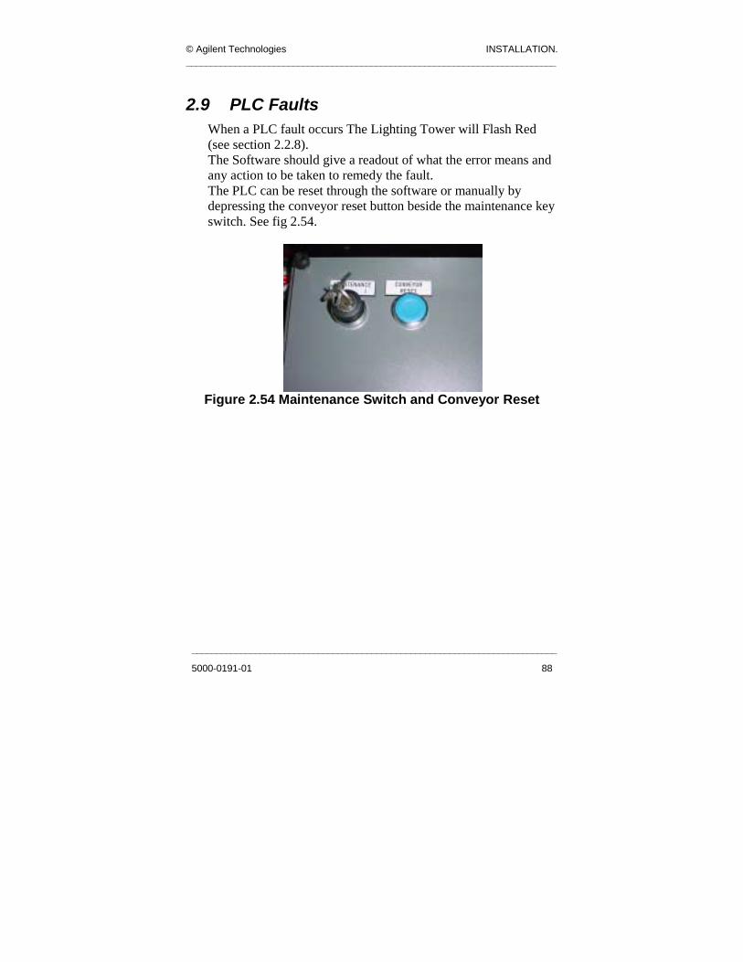
© Agilent Technologies INSTALLATION. ____________________________________________________________________________
___________________________________________________________________________
5000-0191-01 88
2.9 PLC Faults When a PLC fault occurs The Lighting Tower will Flash Red (see section 2.2.8). The Software should give a readout of what the error means and any action to be taken to remedy the fault. The PLC can be reset through the software or manually by depressing the conveyor reset button beside the maintenance key switch. See fig 2.54.
Figure 2.54 Maintenance Switch and Conveyor Reset
MAINTENANCE © Agilent Technologies ____________________________________________________________________________
________________________
89
Chapter 3
3 . 0 Mai n te na nc e
Chapter Contents
3.1 Introduction ..................................................................... 90 3.2 Electrical Maintenance ................................................... 91 3.3 X-Y Table Maintenance.................................................. 95 3.4 Conveyor M ....................................... 99 3.5 Pneumatic M ..................................... 101 3.6 General Ma
This chapter describes
possible it refers to t
involved. They are co
strictly adhered to and
Maintenance
aintenance ............
aintenance ..........
____________________________________________________
5000-0191-01
intenance.................................................... 103
Summary a maintenance schedule for the inspection system. Where
he electrical drawing numbers that describe the circuits
ntained in a separate document. This schedule must be
be performed only by qualified personnel.

© Agilent Technologies MAINTENANCE. ____________________________________________________________________________
___________________________________________________________________________
5000-0191-01 90
3.1 Introduction Maintenance is divided into weekly, monthly, quarterly and yearly schedules. It is also divided into five main sections, each covering an area on the machine. These areas are as follows:
• Electrical Maintenance. • X-Y table Maintenance. • Conveyor Maintenance. • Pneumatic Maintenance. • General Maintenance.
WARNING Maintenance must only be carried out by trained
personnel.

MAINTENANCE © Agilent Technologies ____________________________________________________________________________
____________________________________________________________________________
91 5000-0191-01
3.2 Electrical Maintenance
3.2.1 Weekly
Make sure the computer has been shutdown correctly before this is done.
1. Visually inspect the electrical control panel by turning off the machine at the OFF/ON switch and turning the isolator handle in the OFF position. Open the back door.
2. Inspect all electrical equipment on the machine for damaged contacts, exposed wire cores and frayed insulation.
3. Ensure there are no items in front of the transformer panel; i.e. check that the vent is kept clear of obstruction. Clean vent if necessary.
4. Clean the Optical Sensors with a dry cloth. 5. Pull out the PC Drawer and check the cables going into the
PC, ensure that they are not loose. 6. Pull out the Motor Controller Drawer and check the cables
going into the Motor Controller chassis. Check that they are not loose.
7. Inspect the X-Y Table and check all cables and connectors, 8. Move the X-Y Table by hand, ensure that it moves freely
and is not obstructed in movement throughout its full movement envelope on both X and Y axes.
9. Power back up the machine and start the SJ50 software. 10. Test the E-Stop circuitry by opening and closing the hood
while resetting the E-Stop circuit using the E-Stop Reset button at the front of the machine, repeat this using the emergency stop push/pull actuator.
11. Release the E-Stop and press the reset switch. 12. Cycle boards through the machine and watch its operation
for any faults. 13. Start the AWA application.

© Agilent Technologies MAINTENANCE. ____________________________________________________________________________
___________________________________________________________________________
5000-0191-01 92
14. Home Auto Width Adjust, move to 100mm, measure both sides of conveyor to ensure that calibration of AWA is good.
15. Remove the front electrical panel cover as shown previously, and check all connections on the Lighting Controller, Terminals and PLC Modules.
16. Check all cables on the Lighting Head and X-Y Table and ensure that no wires are loose or damaged.
3.2.2 Monthly 1. Carry out the weekly routine. 2. Open the Pneumatic Panel and check the terminals and
solenoid valves connections.
3.2.3 Quarterly 1. Carry out monthly routine. 2. When inspecting the control panel, check the tightness of the
connections at random; ensure that no wires in the terminals have become loose.
3. Clean and lube the gantry rails.
3.2.4 Yearly 1. Isolate the SJ-50 machine from mains supply. Take off
bottom side panels and open rear doors to Control Panel, physically check all electrical connections on the machine.
• Main Control Panel. • X-Y Table. • PC. • Motor Controller. • Pneumatic Control Panel. • Transformer. • All Earth cables. • All connectors.

MAINTENANCE © Agilent Technologies ____________________________________________________________________________
____________________________________________________________________________
93 5000-0191-01
2. Check the insulation resistance of the mains voltage supplies. Follow this procedure carefully.
Only a qualified technician should carry out the following test.
This test will give an indication that the insulation resistance of the cables and mains supply to the body of the machine is intact and complies with the relevant standards. 1. Power off the machine. 2. Switch off the Main Isolator. 3. Disconnect the mains plugs to the Monitor, PC, Motor
Controller, plug out the Paragon Drives and the power socket.
4. Plug out the power plugs supplying the conveyor and AWA Motor Paragon Drives. See fig 3.1.
Figure 3.1 Plug out the Power Plugs
5. Disconnect the 230V side of the following Power Supply 1
(PS1), Power Supply 2 (PS2) and Power Supply 3 (PS3); and leave the loose wires apart and not touching. PS1 and PS2 are located in the Back Door Control Panel.
6. Using an insulation resistance tester (Note that this is 500V DC) check between L1 and Earth. There should be a reading of >1 M ohm.
7. Then check between N1 and Earth. It should have the same reading.
8. Check again to ensure all equipment stated above is disconnected for safety.
Power plugs

© Agilent Technologies MAINTENANCE. ____________________________________________________________________________
___________________________________________________________________________
5000-0191-01 94
9. Check resistance between L2 and Earth, disconnect earth bonding wire number 2003-2014 at the main Earth point on the Control Panel, leave this in free space. Check between N2 and Earth and between L2 and N2, all resistance readings should be >1M Ohm.
10. Check the reading for Cable 14 to Earth, and then Cable 13 to Earth and finally Cable 13 to 14. Again the reading should be > 1M ohm, these cables are on KM1 off the main contactor. For more information refer to Electrical Drawings 2005-0327.
11. Open the transformer panel and check the condition of the transformer. Examine it for any of the following: • Discoloured, blistered or cracked transformer coating. • Cable and crimp integrity. • Broken or chipped terminals. • Blackening of transformer guard.
12. Check all terminal connections on the machine and complete the monthly routine.
13. Check DC power supply unit outputs. PS1 (24V), PS2(12V) and PS3(5V).
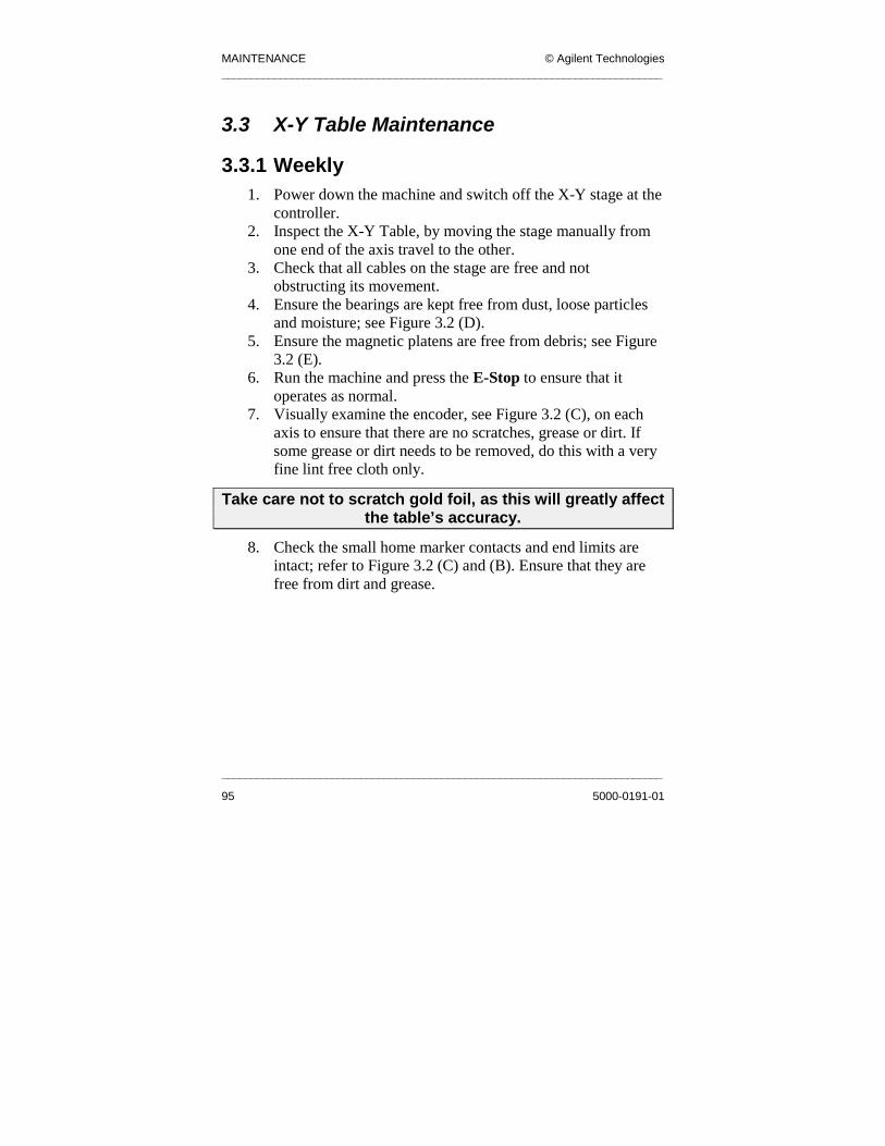
MAINTENANCE © Agilent Technologies ____________________________________________________________________________
____________________________________________________________________________
95 5000-0191-01
3.3 X-Y Table Maintenance
3.3.1 Weekly 1. Power down the machine and switch off the X-Y stage at the
controller. 2. Inspect the X-Y Table, by moving the stage manually from
one end of the axis travel to the other. 3. Check that all cables on the stage are free and not
obstructing its movement. 4. Ensure the bearings are kept free from dust, loose particles
and moisture; see Figure 3.2 (D). 5. Ensure the magnetic platens are free from debris; see Figure
3.2 (E). 6. Run the machine and press the E-Stop to ensure that it
operates as normal. 7. Visually examine the encoder, see Figure 3.2 (C), on each
axis to ensure that there are no scratches, grease or dirt. If some grease or dirt needs to be removed, do this with a very fine lint free cloth only.
Take care not to scratch gold foil, as this will greatly affect the table’s accuracy.
8. Check the small home marker contacts and end limits are intact; refer to Figure 3.2 (C) and (B). Ensure that they are free from dirt and grease.

© Agilent Technologies MAINTENANCE. ____________________________________________________________________________
___________________________________________________________________________
5000-0191-01 96
Figure 3.2 Gantry Schematic
3.3.2 Monthly 1. Carry out weekly routine. 2. When inspecting the connections on the stage and at the
controller check the integrity of the connectors at random.

MAINTENANCE © Agilent Technologies ____________________________________________________________________________
____________________________________________________________________________
97 5000-0191-01
3.3.3 Quarterly • Carry out Monthly routine. • Carry out the following procedure for lubricating and
cleaning of the stage. 1. Turn off controller and activate the E-Stop. 2. Drive the stage to one end of its travel. 3. Open the hood. 4. Remove any accumulated dust or debris from inside of the
assembly. 5. Vacuum-clean the base of the table. 6. Remove any dirty or dried lubricant from the bearing guides;
refer to Figure 3.2 (D). Use a clean cloth wipe along the rails to clean the bearing guides. A cotton swab soaked in solvent will suffice to remove stubborn debris.
7. After the solvent has evaporated (if used), apply a thin, continuous film of lubricant to the bearing guides. A good quality natural bristle artist’s brush is an excellent applicator for this.
8. Lubricate the four LMG Bearing Trucks on each stage, Figure 3.2 (A). (See Important notes on lubrication). Use a grease gun with a grease nipple (type UU or SS); refer to Figure 3.2 (F).
9. Close the hood. 10. Restore power to the machine.
WARNINGFailure to lubricate the stage at quarterly intervals
invalidates all warranties.

© Agilent Technologies MAINTENANCE. ____________________________________________________________________________
___________________________________________________________________________
5000-0191-01 98
3.3.4 Yearly 1. Carry out quarterly routine. 2. Take off the cover of the motor controller and check the
interior for loose connections. Ensure that the internal fan is functioning.
3. Using a 8mm Allen key, ensure that the securing bolts on the table have not become loose. (Tighten to 77 Nm)
Imp or t ant Not es on Lu br i ca t i on Be sure to use a clean dry, soft lint free cloth for cleaning. Take the time to inspect the linear motor drives for wear and signs of damage. Further disassembly of the stage is NOT recommended, since proper setting and calibration can only be carried out at the factory.
Re comm en de d L ub r ic ant s 1. Dow Corning’s Molykote 44 is recommended. 2. Only use lithium based grease.

MAINTENANCE © Agilent Technologies ____________________________________________________________________________
__________________________________________________
99
3.4 Conveyor Maintenance
3.4.1 General Warnings NEVER clean with a compressed air stream. It may cause dirt etc. to get lodged into the motor shaft. Use a vacuum cleaner to remove loose dust or dirt. NEVER disassemble the motors. Details on the conveyor can be seen in the figure below:
Figure 3.3 Conveyor Com
Entry Sensor
Motor
Board Clamp
Board Clamp
Fixed Rail
Adjustable Rail
Base Rail
Exit Sensor
ponents
__________________________
5000-0191-01

© Agilent Technologies MAINTENANCE. ____________________________________________________________________________
___________________________________________________________________________
5000-0191-01 100
3.4.2 Weekly 1. Check the function of the sensors by placing a sample board
over them. Look at the indicator light on each of the sensors. 2. Move the lighting head over each sensor and make sure they
are not activated by it. 3. Check soundness of all motor housings. 4. Wipe off edge belts with recommended cleaning agent 409
spray cleaner. An alternative is to use alcohol or equivalent. 5. Vacuum clean the base of the machine.
3.4.3 Monthly 1. Carry out the weekly maintenance routine in full. 2. Ensure all bearings are free running and belt tension is tight. 3. Ensure that conveyor belts are not twisted on either rail.
3.4.4 Yearly 1. Carry out monthly maintenance routine in full. 2. Check the electrical connections at the conveyor motors and
in the front electrical enclosure. Make sure all connections are intact and securely fitted.
3. Check all mounting screws and hardware on the machine. 4. Systematically check all nuts, bolts and screws on rails,
lifting mechanism, air cylinders, bearings and mountings for all hardware.
3.4.5 Two Yearly 1. Lubricate the conveyor bearings with THK AFB lubricant. 2. Use a grease gun with a grease nipple (type UU or SS) 3. Care should be taken so as not to over lubricate the bearings.
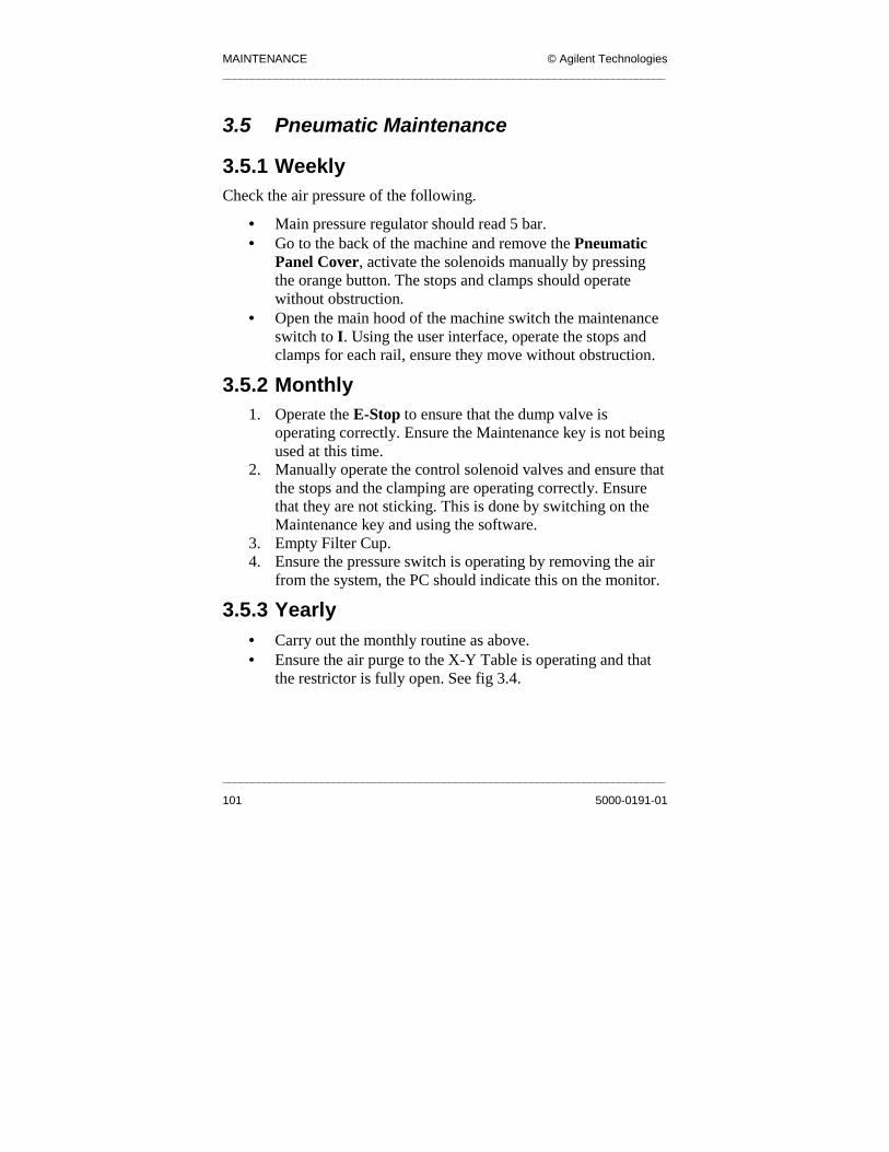
MAINTENANCE © Agilent Technologies ____________________________________________________________________________
____________________________________________________________________________
101 5000-0191-01
3.5 Pneumatic Maintenance
3.5.1 Weekly Check the air pressure of the following.
• Main pressure regulator should read 5 bar. • Go to the back of the machine and remove the Pneumatic
Panel Cover, activate the solenoids manually by pressing the orange button. The stops and clamps should operate without obstruction.
• Open the main hood of the machine switch the maintenance switch to I. Using the user interface, operate the stops and clamps for each rail, ensure they move without obstruction.
3.5.2 Monthly 1. Operate the E-Stop to ensure that the dump valve is
operating correctly. Ensure the Maintenance key is not being used at this time.
2. Manually operate the control solenoid valves and ensure that the stops and the clamping are operating correctly. Ensure that they are not sticking. This is done by switching on the Maintenance key and using the software.
3. Empty Filter Cup. 4. Ensure the pressure switch is operating by removing the air
from the system, the PC should indicate this on the monitor.
3.5.3 Yearly • Carry out the monthly routine as above. • Ensure the air purge to the X-Y Table is operating and that
the restrictor is fully open. See fig 3.4.

© Agilent Technologies MAINTENANCE. ____________________________________________________________________________
___________________________________________________________________________
5000-0191-01 102
Figure 3.4 SJ50 Pneumatics Panel
Pressure Regulator
Pressure Gauge/Switch
Air Input Tube
Solenoids
Air tubes to X-Y Table
Filter cup
Air tubes to Clamps and
Stops
PLC IO
Restrictor

MAINTENANCE © Agilent Technologies ____________________________________________________________________________
____________________________________________________________________________
103 5000-0191-01
3.6 General Maintenance
3.6.1 Weekly 1. Clean down the machine panels. 2. Clean the PC filter, if fitted. 3. Check fan on the DR600 Motor Controller, you should
hear it running when the drawer is pulled fully out. 4. Check PC power supply fan is running. Open the PC drawer
and feel the air intake at the power supply. 5. Check PC CPU fan is running, if fitted. The fan is located at
the rear of the PC. 6. Run a board through the machine and ensure that the
machine is operating correctly.
3.6.2 Monthly • Carefully clean the Camera Lens. Only use a proper cleaning
solution and a lint free cloth.
© Agilent Technologies TROUBLESHOOTING. ____________________________________________________________________________
___________________________________________________________________________
5000-0191-01 104
Chapter 4
4 . 0 Tr o ubl es ho ot in g Gui de
Chapter Contents
4.1 System Power................................................................. 105 4.2 Conveyor ........................................................................ 106 4.3 Other Electrical ............................................................. 111 4.4 Pneumatics ..................................................................... 114
Summary
This chapter is intended to assist the user to solve problems that they may
encounter with their system. It describes the sequence to follow when the system
does not function within normal operating parameters. We have concentrated on
the failure modes that happen most frequently and with the greatest effect to
productivity, i.e. those that would cause the line to stop. Use this chapter in
conjunction with the electrical drawings issued with the document pack.
Troubleshooting

TROUBLESHOOTING. © Agilent Technologies ____________________________________________________________________________
____________________________________________________________________________
105 5000-0191-01
4.1 System Power For the locations of terminals, relays, PLC displays, PSUs and MCBs refer to Electrical Drawings, depending on which system you have.
4.1.1 Power failure or no Power Response • Is there power at the main supply? • Is the Main Isolator in the ‘ON’ position? • Are Q1 and Q2, the main RCD in the ‘ON’ position? • Is the Power On light illuminated? • Is the key switch in the ON position? • Check Q3, the 24V PSU is ON • Check Q10, 24V DC Off/On Breaker is ON • Check the supply voltage at the main terminals.
4.1.2 Mains Transformer is not Working • Check MCB Q2 is ON. • Check main MCB Q1 is ON. • Ensure there is the customer-selected voltage at
terminals L1 and N1. • Ensure there is 230V at terminals L2 and N2, and 55V at
terminals L3 and N3
WARNING: Ensure machine is first isolated from the Mains supply.
• Check transformer resistance (>1 ohm), at terminals L1 and N1.
• Check transformer resistance (>1 ohm), at terminals L2 and N2.
• Check cables and terminals at transformer are intact.
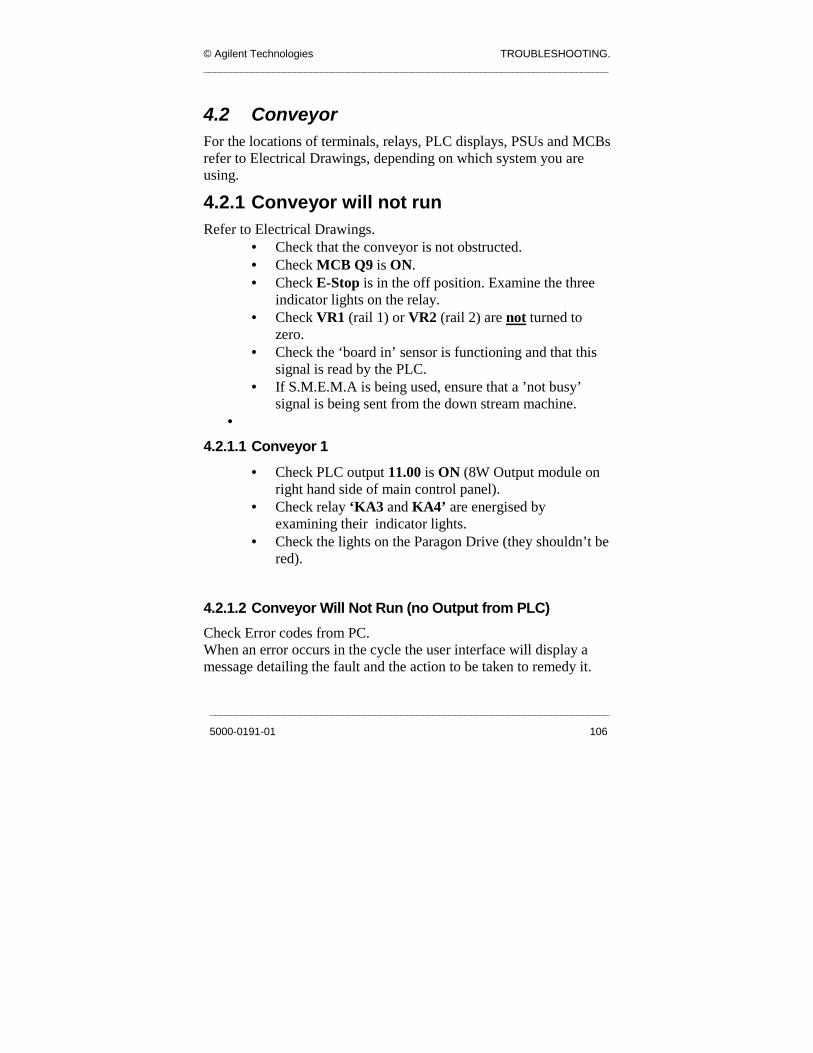
© Agilent Technologies TROUBLESHOOTING. ____________________________________________________________________________
___________________________________________________________________________
5000-0191-01 106
4.2 Conveyor For the locations of terminals, relays, PLC displays, PSUs and MCBs refer to Electrical Drawings, depending on which system you are using.
4.2.1 Conveyor will not run Refer to Electrical Drawings.
• Check that the conveyor is not obstructed. • Check MCB Q9 is ON. • Check E-Stop is in the off position. Examine the three
indicator lights on the relay. • Check VR1 (rail 1) or VR2 (rail 2) are not turned to
zero. • Check the ‘board in’ sensor is functioning and that this
signal is read by the PLC. • If S.M.E.M.A is being used, ensure that a ’not busy’
signal is being sent from the down stream machine. •
4.2.1.1 Conveyor 1 • Check PLC output 11.00 is ON (8W Output module on
right hand side of main control panel). • Check relay ‘KA3 and KA4’ are energised by
examining their indicator lights. • Check the lights on the Paragon Drive (they shouldn’t be
red).
4.2.1.2 Conveyor Will Not Run (no Output from PLC) Check Error codes from PC. When an error occurs in the cycle the user interface will display a message detailing the fault and the action to be taken to remedy it.

TROUBLESHOOTING. © Agilent Technologies ____________________________________________________________________________
____________________________________________________________________________
107 5000-0191-01
4.2.1.3 No Connection to AWA Drive from GUI • Check serial cable is plugged into the Paragon Docking
Station. See fig 4.1
Fig 4.1 Serial cable plugged into docking station
• Check E-Stop is reset. • Check power to Paragon Drive, look for indicator lights
on the Paragon Drive. • Check 24V DC power to Paragon Drive. • Check output of transformer (TV2) is 55V AC between
L3 and N3 terminals on the back Electrical Control Panel.
• Check Q9 is ON. • Check the Paragon Drive coms are set up correctly.
For more information refer to 2.8.3. These settings should be set to:
Baud Rate 9600 Stop Bits 1 Data Bits 8 Com This can be one of the following values:
1 - Lighting Controller

© Agilent Technologies TROUBLESHOOTING. ____________________________________________________________________________
___________________________________________________________________________
5000-0191-01 108
2 - PLC 3 - AWA 4 – barcode Reader
• Check AWA Manual switch is in the off position.
4.2.1.4 Drives Won’t Move/ Home/ Move to a Given Width. • Check that motors are not slipping on their coupling. • Check the position of the AWA Manual switch. • Check that there is nothing obstructing the conveyor. • Check E-Stop is reset. • Check power to the Paragon Drive, look for indicator
lights on the Paragon Drive. The middle LED should be green or orange.
• Check 24V DC power to Paragon Drive. • Check output of transformer (TV2) is 55V AC between
L3 and N3. • Check Q9 is ON. • Check KP1 on Single rail is on to energize all motors.
This is done by checking if the green LED is lit. • Check that the PLC is not allowing the move. The PLC
may not allow the moves if there is a board in the machine or some of the sensors are triggered.
• Ensure that PLC output 10.10 is OFF. The PLC output should be 10. See fig 4.2.
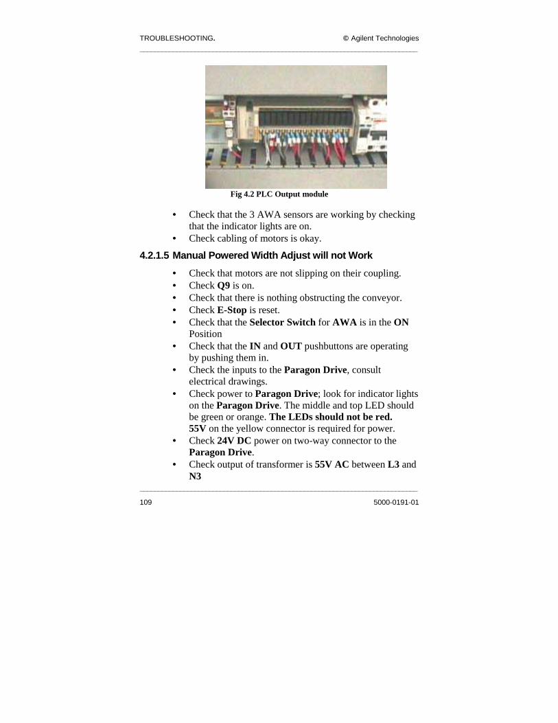
TROUBLESHOOTING. © Agilent Technologies ____________________________________________________________________________
____________________________________________________________________________
109 5000-0191-01
Fig 4.2 PLC Output module
• Check that the 3 AWA sensors are working by checking
that the indicator lights are on. • Check cabling of motors is okay.
4.2.1.5 Manual Powered Width Adjust will not Work • Check that motors are not slipping on their coupling. • Check Q9 is on. • Check that there is nothing obstructing the conveyor. • Check E-Stop is reset. • Check that the Selector Switch for AWA is in the ON
Position • Check that the IN and OUT pushbuttons are operating
by pushing them in. • Check the inputs to the Paragon Drive, consult
electrical drawings. • Check power to Paragon Drive; look for indicator lights
on the Paragon Drive. The middle and top LED should be green or orange. The LEDs should not be red. 55V on the yellow connector is required for power.
• Check 24V DC power on two-way connector to the Paragon Drive.
• Check output of transformer is 55V AC between L3 and N3

© Agilent Technologies TROUBLESHOOTING. ____________________________________________________________________________
___________________________________________________________________________
5000-0191-01 110
• Check KP1 on Single rail is on to energize all motors. • Check that the PLC is not allowing the move. The PLC
may not allow the moves if there is a board in the machine or some of the sensors are triggered.
• Ensure that PLC output 10.10 is off. • Check cabling of motors is okay.
4.2.1.6 Rails not Aligning Properly For more information, refer to Chapter 2.8.2 1. Perform AWA calibration. 2. Check that the left minimum sensor and the right alignment
sensor are in line. 3. Check all sensors are working by placing something, for
example a piece of card, at various parts of the rail to see if it triggers the associated sensor/input.
4. Ensure that when the AWA software is executing the aligning operation, the relay KM4 is activated so as to allow the right side motor to be moved.
5. Check cabling of motors is okay.

TROUBLESHOOTING. © Agilent Technologies ____________________________________________________________________________
____________________________________________________________________________
111 5000-0191-01
4.3 Other Electrical Troubleshooting For the locations of terminals, relays, PLC displays, PSUs and MCBs refer to Electrical Drawings, depending on which system you have.
4.3.1 Lighting Tower will not Operate Refer to Electrical Drawings.
• Is it plugged in? • Go to the machine I/O menu and activate all lights in
machine I/O menu • Check PLC is operating. • Check connector is intact and undamaged.
4.3.2 No 24V Supply Refer to Electrical Drawings.
• Check 24V supply PS1 by either measuring the output of the power supply or by looking at the Indicator light (the latter solution is not as good a test as the previous solution).
• Check MCB Q3 is ON. • Check MCB Q11 is ON (24V control MCB).
4.3.3 Safety Relay will not Reset Refer to Electrical Drawings.
• Check 24V supply across the relay terminals A1-A2. • Check emergency stop and door interlock is functioning
correctly. This is done by checking the continuity across terminals: XB6-1 & XB6-2, and XB2-7 & XB2-8 for circuit no.1. XB2-9 & XB2-10 and XB6-3 & XB6-4 for circuit no. 2.
• There are three indicator lights on the safety relay. - Top light represents power on - Two bottom lights representing circuit number 1 and circuit number 2 respectively.
© Agilent Technologies TROUBLESHOOTING. ____________________________________________________________________________
___________________________________________________________________________
5000-0191-01 112
• When the three lights are on this means that, the relay is functioning correctly.
• Check that all contacts and terminations are intact. • Check PLC output 10.04. This is done by checking if the
corresponding LED on the PLC module is on. • Check reset circuit, activated by the hardware
push/button that shorts out terminals XB5-7 and XB5-8 on the control panel.
• If the emergency stop is on and there is no indication on the monitor, see PLC input 00.02. Check the LED on the PLC module 00 is on.
4.3.4 X-Y Table Motor Controller not Operating
• Is MCB Q6 on? • Is the local on/off switch in the ON position? This is the
main power switch on the front of the DR600 Motor Controller.
• Is there an emergency stop condition? Examine the three indicator lights on the safety relay.
• Are the safety circuit contacts functioning correctly? To do this, disconnect cable 2003-2005 going into the motor controller. There are three pairs of pins. With the emergency stop off, check that there is continuity between these pins. Pins 2 and 10 Pins 11 and 12 Pins 13 and 14.
• Check all cables are tight and in position.
4.3.5 Monitor is not Operating • Is the monitor switched on and plugged in? • Check MCB Q8 is on. Check cables for tight
connections.

TROUBLESHOOTING. © Agilent Technologies ____________________________________________________________________________
____________________________________________________________________________
113 5000-0191-01
• If UPS (Uninterruptible Power Supply) is installed, make sure that it’s switched on.
4.3.6 PC is not Operating • Is the PC plugged in and switched on? • Check MCB Q7 is on. • If UPS installed, make sure that it’s switched on.
4.3.7 Camera will not Operate 1. Check 12V PSU. 2. Check MCB Q4 is ON. 3. Check 12V DC at terminal XB4-6 & XB4-7. This is located at
the back of the Control Panel. 4. Check cable 2003-0416 and 2003-0417 on camera to ensure they
are connected correctly. 5. Check all connections to and from the camera. Ensure there is
continuity between the ends of the co-axial signal cable form the camera to the framegrabber card at the back of the PC.
6. Check software configuration

© Agilent Technologies TROUBLESHOOTING. ____________________________________________________________________________
___________________________________________________________________________
5000-0191-01 114
4.4 Pneumatics For the locations of terminals, relays, PLC displays, PSUs and MCBs refer to Electrical Drawings.
4.4.1 No Air Supply 1. Check source of air. 2. Check air pressure is set at 5 bar at regulator. 3. Check E-stop is not pressed or safety relay is engaged.
4.4.2 Dump Valve will not Function 1. Check air pressure is set to 5 bar at regulator. 2. Check emergency stop is OFF. 3. Check for indicator light on valve. 4. Check 24V supply at terminals XBP-5 and XBP-6 in the
pneumatic panel.
4.4.3 Stops will not Engage • Refer to Electrical Drawings.
1. Check that the PLC outputs 13.00 (rail 1) or 13.02 (rail 2) is on. 2. Check solenoid valve YV2 or YV4 is ON. 3. Check air supply is ON. 4. Check dump valve YV1 is energized examining the indicator
light. 5. Check for kinks in the tubes.
4.4.4 Clamp will not Engage • Refer to Electrical Drawings.
1. Check that the PLC output 13.01 or 13.03 is ON. 2. Check solenoid valves YV3 and YV5 are ON. 3. Check air supply is ON. 4. Check dump valve YV1 is energised examining the indicator
light. • Check for kinks in the tubes.

TROUBLESHOOTING. © Agilent Technologies ____________________________________________________________________________
____________________________________________________________________________
115 5000-0191-01
4.4.5 No purge to X-Y Table 1. Check Dump valve. 2. Check air supply at the regulator. 3. Check for kinked tubes. 4. Check for air leaks.

© Agilent Technologies SYSTEM SPECIFICATIONS. ____________________________________________________________________________
___________________________________________________________________________
5000-0191-01 116
Chapter 5
5 . 0 Sys t em Sp ec i f i ca t io ns
Chapter Contents
5.1 SJ-50 Functional Specifications ................................... 117
Summary This chapter is intended to outline the systems specifications. It includes the
physical specs like footprint and electrical and pneumatic inputs as well as the
software operating system. These are accurate at the time of printing and are
liable to change. We recommend that you contact your sales contact or Local
Support representative for the latest functional specifications.
System Specifications

SYSTEM SPECIFICATIONS. © Agilent Technologies ____________________________________________________________________________
____________________________________________________________________________
117 5000-0191-01
5.1 SJ-50 Functional Specifications
Software System Operating system Windows NT™ V4.00. User Interface Graphical User Interface with password
protected user levels. Data Transfer Interfaces
Any ASCII file format via floppy disk or Ethernet (TCP/IP or MS Network).
Hardware System Computer System High Speed Pentium III™ based PC in an
industrial rack. Host Communications
Thin wire or twisted pair Ethernet supporting TCP/IP or MS Network.
CAD File Formats CAMCAD. Imaging Hardware Matrox Meteor-2DIG/2
Matrox G450 32MB Dual AGP card. Camera System Camera: CCD 1280 x 1024 pixels,
Electronic Shutter. Optics: Telecentric gauging lens. Field of View: 26mm x 20mm @ a Pixel Size of 20µm. Illumination: Multi-layer LED.
X-Y Robot System Gantry robot system with linear motors and linear encoders. Travel: 590mm x 490mm or 490mm x 490mm. Velocity (x, y): 1500mm (60”) /Sec. Encoder Resolution: 1µm.

© Agilent Technologies SYSTEM SPECIFICATIONS. ____________________________________________________________________________
___________________________________________________________________________
5000-0191-01 118
Board Clearance Depends on application: Top side either 28mm (as standard) or 12mm (with low-level lighting fitted). Bottom side 50mm.
Conveyor System SMEMA standard conveyor supplied with speed adjustment.
Position
Depends on application Post-Oven/Post-Wave/2D Paste (with h/w modifications). Pre-Oven. Pre-placement in the SMT manufacturing process.
Enclosure The enclosure is designed to conform to CE Mark standards for electrical and mechanical industrial safety. Auto width adjustment available as standard.
Supply Facilities Electricity • 208-240V 25A …100-110V 40A. Air Requirements • Clean filtered air at 6 Bar,4CFM
• 12 mm or 6mm input line. Operating Temperature
• 10 to 35° C.
Physical Dimensions Footprint • 994mm x 1548mm. Height • Approx. 2100mm including Light
tower. • Approx. 1400mm excluding
Light tower. Weight • 1400 kg (approximate).

SYSTEM SPECIFICATIONS. © Agilent Technologies ____________________________________________________________________________
____________________________________________________________________________
119 5000-0191-01
Appendix I Requirements Listing 1. Set of Metric Hexagonal Allen keys; 1.5, 2, 2.5, 3, 4, 4.5, 5, 5.5,
6, 7, 8, 9, 10. 2. Set of insulated slotted screwdrivers: 2.8, 4.0, 5.5, and 6.5. 3. Pistol grease gun. 4. Natural Bristle artist’s brush. 5. Lint-free cloth. 6. Anti static cleaning spray. 7. Dow Corning Molykote 44 grease. 8. Fast dry precision cleaner solvent; RS#203-0716. 9. Aerosol optical instrument cleaner; RS#217-3857. 10. Megger BM101/4 - Insulation resistance tester. 11. Flow-rate sensor.

© Agilent Technologies SYSTEM SPECIFICATIONS. ____________________________________________________________________________
___________________________________________________________________________
5000-0191-01 120
Appendix II Maintenance Checklists Site:________________ Completion
Date:_______________________
System Type:________________
System Serial Number:____________________
Weekly Maintenance Schedule
Performed by:______________________
Good/Bad
Comments and/or Corrective Actions
(if necessary) Electrical Inspect El. Control Panel
Inspect mains transformer
Examine cables to PC
Examine cables to the XY table controller
Inspect connections to XY gantry
Test E-Stop and door interlock
Test clamping and stop mechanisms
Test E-Stop reset switch
Test System Cycle

SYSTEM SPECIFICATIONS. © Agilent Technologies ____________________________________________________________________________
____________________________________________________________________________
121 5000-0191-01
X-Y Table
Examine X-Y table motion
Examine cabling
Inspect bearings
Inspect magnet platten
Inspect encoder
Inspect limit switches
Conveyor
Examine moving parts Inspect conveyor belts
Test all sensors
Clean belts
Pneumatics
Check the systems pressure settings

© Agilent Technologies SYSTEM SPECIFICATIONS. ____________________________________________________________________________
___________________________________________________________________________
5000-0191-01 122
General
Wipe down the machine panels
Clean the PC filter
Check operation and direction of motor controller fan
Check operation and direction of PC fans
Inspect and clean camera lens
Observe one board cycling through the machine
Overall Comments on System:
Actions Required: 1 2 3 4

SYSTEM SPECIFICATIONS. © Agilent Technologies ____________________________________________________________________________
____________________________________________________________________________
123 5000-0191-01
Site________________ Completion
Date:_____________________
System Type:______________
System Serial Number:__________________
Monthly Maintenance Schedule
Performed by:__________________________
Good/Bad
Comments and/or Corrective Action
(if necessary) Electrical Inspect El. Control Panel
Inspect mains transformer
Clean optical sensors
Examine cables to PC
Examine cables to the XY table controller
Inspect connections to XY table
Test E-Stop and door interlock
Test clamping and stop mechanisms
Test E-Stop reset switch
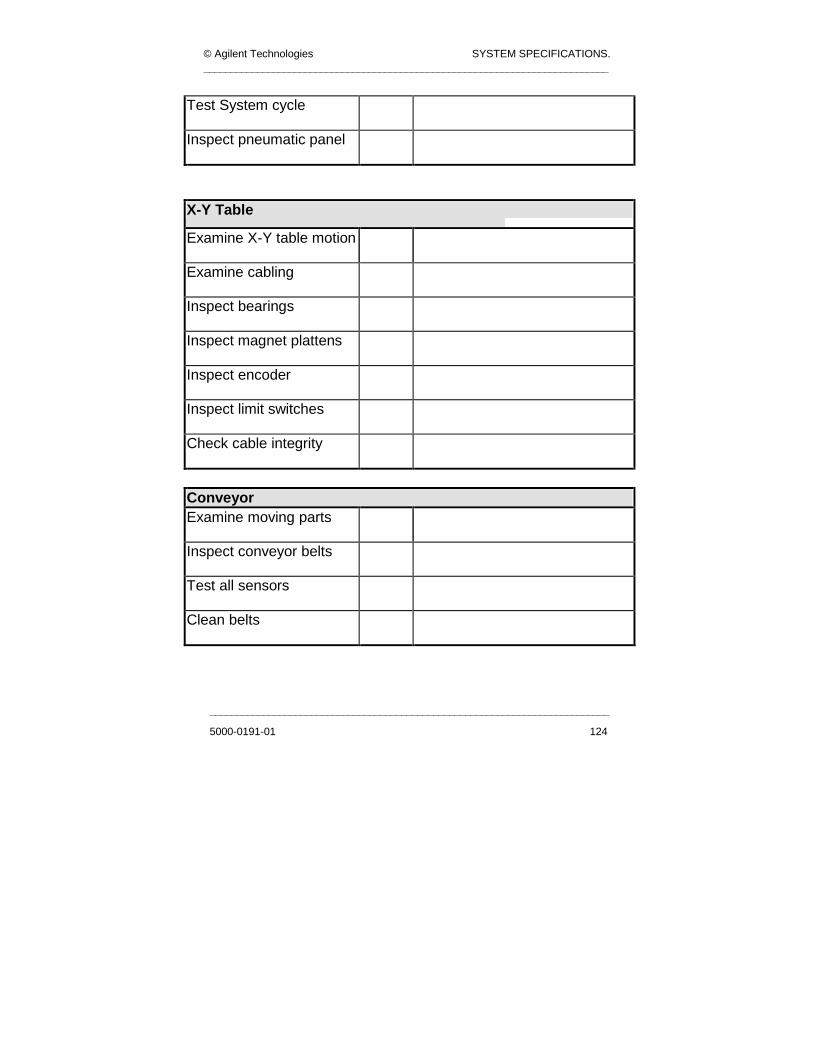
© Agilent Technologies SYSTEM SPECIFICATIONS. ____________________________________________________________________________
___________________________________________________________________________
5000-0191-01 124
Test System cycle
Inspect pneumatic panel
X-Y Table
Examine X-Y table motion
Examine cabling
Inspect bearings
Inspect magnet plattens
Inspect encoder
Inspect limit switches
Check cable integrity
Conveyor Examine moving parts
Inspect conveyor belts
Test all sensors
Clean belts

SYSTEM SPECIFICATIONS. © Agilent Technologies ____________________________________________________________________________
____________________________________________________________________________
125 5000-0191-01
Pneumatics Check the systems pressure settings
Test dump valve
Test solenoid valves
Test pressure sensor
General
Wipe down the machine panels
Clean the PC filter
Check direction of motor controller fan
Check operation and direction of PC fans
Inspect and clean camera lens
Cycle a PCB through the machine
Overall Comments on System:
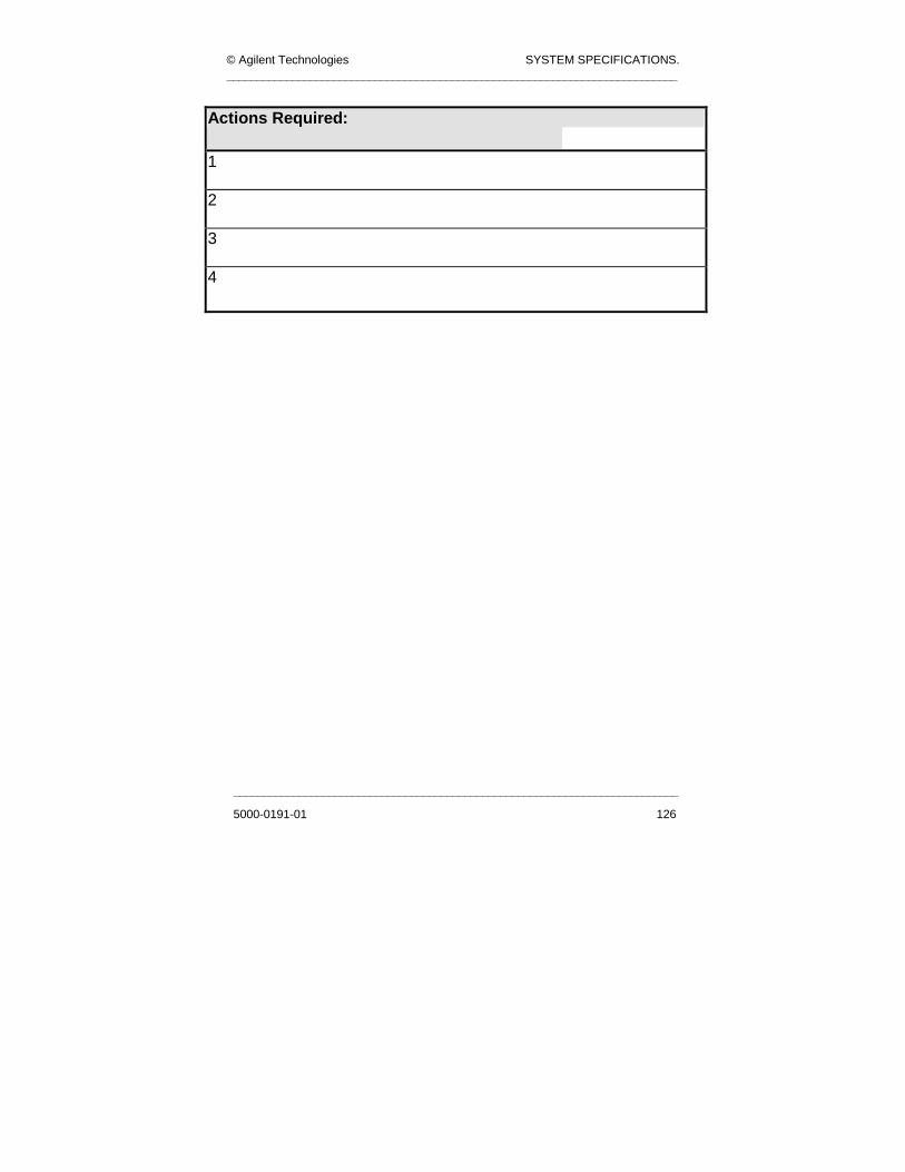
© Agilent Technologies SYSTEM SPECIFICATIONS. ____________________________________________________________________________
___________________________________________________________________________
5000-0191-01 126
Actions Required:
1 2 3 4

SYSTEM SPECIFICATIONS. © Agilent Technologies ____________________________________________________________________________
____________________________________________________________________________
127 5000-0191-01
Site:___________________ Completion Date:__________________
System Type:__________________
System Serial Number:_______________
Quarterly Maintenance Schedule
Performed by: ________________________
Good/Bad
Corrective Action (if necessary)
Electrical Inspect El. Control Panel
Inspect mains transformer
Clean optical sensors
Examine cables to PC
Examine cables to the XY table controller
Inspect connections to XY table
Test E-Stop and door interlock
Test clamping and stop mechanisms
Test E-Stop reset switch
Test System cycle
Inspect pneumatic panel

© Agilent Technologies SYSTEM SPECIFICATIONS. ____________________________________________________________________________
___________________________________________________________________________
5000-0191-01 128
Check Connections in control panel
X-Y Table Examine X-Y table motion
Examine cabling
Inspect bearings
Inspect magnet plattens
Inspect encoder
Inspect limit switches
Check cable integrity
Lubricate the guide rails
Conveyor Examine moving parts
Inspect conveyor belts
Test all sensors
Clean belts
Lubricate conveyor linear bearings

SYSTEM SPECIFICATIONS. © Agilent Technologies ____________________________________________________________________________
____________________________________________________________________________
129 5000-0191-01
Pneumatics
Check the systems pressure settings
Test dump valve Test solenoid valves
Test pressure sensor
General
Wipe down the machine panels
Clean the PC filter Check operation and direction of motor controller fan
Check operation and direction of PC fans
Inspect and clean camera lens
Cycle a PCB through the machine
Overall Comments on System:

© Agilent Technologies SYSTEM SPECIFICATIONS. ____________________________________________________________________________
___________________________________________________________________________
5000-0191-01 130
Actions Required: 1 2 3 4

SYSTEM SPECIFICATIONS. © Agilent Technologies ____________________________________________________________________________
____________________________________________________________________________
131 5000-0191-01
Location:______________ Completion Date:_________________
System Type:__________________
System Serial Number:______________
Yearly Maintenance Schedule
Performed by:__________________________
Good/Bad
Comments and/or Corrective Action
(if necessary) Electrical Inspect El. Control Panel
Inspect mains transformer
Clean optical sensors
Examine cables to PC
Examine cables to the XY table controller Inspect connections to XY table Test E-Stop and door interlock Test clamping and stop mechanisms Test E-Stop reset switch
Check connections solenoid valves

© Agilent Technologies SYSTEM SPECIFICATIONS. ____________________________________________________________________________
___________________________________________________________________________
5000-0191-01 132
Inspect connections to pneumatic panel Check connections to control panel Check electrical connections Test system insulation resistance Inspect transformer
Test terminals
X-Y Table Examine X-Y table motion
Examine cabling
Inspect bearings
Inspect magnet plattens
Inspect encoder
Inspect limit switches
Check cable integrity
Lubricate the guide rails
Inspect motor controller
Test tightness of base plate bolts

SYSTEM SPECIFICATIONS. © Agilent Technologies ____________________________________________________________________________
____________________________________________________________________________
133 5000-0191-01
Conveyor Examine moving parts
Inspect conveyor belts
Test all sensors
Clean belts
Lubricate conveyor linear bearings Inspect electrical connections Check mounting screws
Check motor cable insulation resistance
Pneumatics
Check the systems pressure settings
Test dump valve Test solenoid valves
Test pressure sensor
Replace main air filter
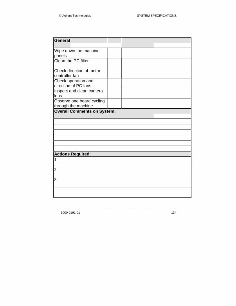
© Agilent Technologies SYSTEM SPECIFICATIONS. ____________________________________________________________________________
___________________________________________________________________________
5000-0191-01 134
General
Wipe down the machine panels Clean the PC filter
Check direction of motor controller fan Check operation and direction of PC fans Inspect and clean camera lens Observe one board cycling through the machine Overall Comments on System:
Actions Required: 1 2 3

www.agilent.com
Agilent TechnologiesTest and Measurement Call CenterP.O. Box 4026 Englewood, CO 80155-4026Tel: +1 800 452 4844
CanadaAgilent Technologies Canada Inc.5150 Spectrum Way, Mississauga, Ontario L4W 5G1Tel: +1 877 894 4414
EuropeAgilent TechnologiesEuropean MarketingP.O. Box 4121180 AK Amstelveen, The NetherlandsTel: +31 20 547 2000
JapanAgilent Technologies Japan Ltd.Measurement Assistance Center9-1, Takakura-Cho, Hachioji-Shi,Tokyo 192-8510, JapanTel: +81 426 56 7832
Latin AmericaAgilent TechnologiesLatin American Region HQ5200 Blue Lagoon DriveSuite #950, Miami, Florida 33126 U.S.A.Tel: +305 267 4245
Australia/New ZealandAgilent Technologies Pty Ltd347 Burwood HighwayForest Hill, Victoria 3131Tel: +1 800 629 485 (Australia)Tel: +0 800 738 378 (New Zealand)
Asia PacificAgilent Technologies24/F, Cityplaza One1111 King’s Road,Taikoo Shing, Hong KongTel: +852 3197 7777
Agilent Technologies IrelandSilverstone House, Ballymoss Road,Sandyford Industrial Estate,Dublin 18, Ireland Tel: +353 1 605 8320Email: [email protected]
Agilent Technologies1348 Busch Parkway, Buffalo Grove, IL. 60089Tel: +1 847 229 8809 Email: [email protected]