The Micro-System - ECE Users Pages
12
1 Prof. G.A. Rincón-Mora http://www.rincon-mora.com Georgia Tech Analog & Power IC Design Lab Self Self- Sustaining, Sustaining, Self Self- Powered, Powered, Power Conscious ICs Power Conscious ICs for Micro for Micro- Scale Systems Scale Systems Prof. Gabriel A. Prof. Gabriel A. Rinc Rincón- Mora Mora Georgia Tech Analog & Power IC Design Lab Georgia Tech Analog & Power IC Design Lab http://www.rincon http://www.rincon- mora.com mora.com 2 Outline Outline • Motivation Motivation • The Future The Future • Integration Barriers Integration Barriers • Approach 1: Harvest Energy Approach 1: Harvest Energy • Approach 2: Extend Runtime Approach 2: Extend Runtime • The Micro The Micro- System System • The Future, Revisited... The Future, Revisited... 2. 5V R F Ana l og 2.5 -5.5V PA Ad a pt i v e Buc k / Bo os t DC -DC C on ve r t e r Fi x ed B uck/ B oo s t DC-DC Conv e rter Dynamic Buc k /B o ost DC-DC C onv e rter Ad a p t i ve & Fi xed R e fe r e nce s (I, V, t ) P ow er Ma nageme nt C ore LCD D a t a 0 1 1 0 0 110 0 .5- 1V P/DSP Co re µ 0 .9-1 .4 V Fu e l Cell 2.7-4 . 2V Thi n-F. Li- I o n Chrgr
Transcript of The Micro-System - ECE Users Pages

1
Prof. G.A. Rincón-Morahttp://www.rincon-mora.com
Georgia Tech Analog & Power IC Design Lab
SelfSelf--Sustaining,Sustaining,SelfSelf--Powered,Powered,
Power Conscious ICsPower Conscious ICsfor Microfor Micro--Scale SystemsScale Systems
Prof. Gabriel A. Prof. Gabriel A. RincRincóónn--MoraMora
Georgia Tech Analog & Power IC Design LabGeorgia Tech Analog & Power IC Design Labhttp://www.rinconhttp://www.rincon--mora.commora.com
22
OutlineOutline
•• MotivationMotivation
•• The FutureThe Future
•• Integration BarriersIntegration Barriers
•• Approach 1: Harvest EnergyApproach 1: Harvest Energy
•• Approach 2: Extend RuntimeApproach 2: Extend Runtime
•• The MicroThe Micro--SystemSystem
•• The Future, Revisited...The Future, Revisited...
2.5V RFAnalog
2.5-5.5VPA
Adaptive Buck/Boost
DC-DC Converter
Fixed Buck/Boost
DC-DC Converter
Dynamic Buck/Boost
DC-DC Converter
Adaptive & Fixed
References (I, V, t)
Power Management Core
LCD
Data
0110
0110
0.5-1VP/DSPCore
µ
0.9-1.
4V
Fuel Cell
2.7-4.
2V
Thin-F. L
i-Ion
Chrgr

2
Prof. G.A. Rincón-Morahttp://www.rincon-mora.com
Georgia Tech Analog & Power IC Design Lab
33
MotivationMotivation•• Demand:Demand: Military reconnaissance, remote space/field meters/monitors, imMilitary reconnaissance, remote space/field meters/monitors, implantable plantable
biomedical devices, and portable/mobile consumer electronics.biomedical devices, and portable/mobile consumer electronics.
Portable (small and compact)Portable (small and compact)
LightweightLightweight
LongLong--Lasting (long life)Lasting (long life)
SelfSelf--PoweredPowered
SelfSelf--SustainingSustaining
•• Desirable Solution: Desirable Solution: Total IntegrationTotal Integration
And for portability and low cost,And for portability and low cost,
Total Chip IntegrationTotal Chip Integration
SystemSystem--onon--Chip (Chip (SoCSoC) ) –– integrate into siliconintegrate into silicon
SystemSystem--inin--Package (Package (SiPSiP) ) –– integrate into the chip packageintegrate into the chip package
SystemSystem--onon--Package (Package (SoPSoP) ) –– annex to the chip packageannex to the chip package
Power Management Front-End Interface Back-End Interface
> Sensors> Filters> Amplifiers> A/D Converters> ...
> D/A Converters> Filters> Amplifiers> Power Drivers> ...
> Bias circuits> References> Regulators> Watch-dog functions> Protection Circuits> ...
TEX T
TEX T
TEX T
TEX T
TEX T
TEX T
TEX T
TEX TTEX T
TEX T
TEX T
TEX T
TEXT
** DerivedDerived
International Technology Roadmap for SemiconductorsInternational Technology Roadmap for Semiconductors11
Year 2000 2001 2002 2003 2004 2005 2008 2011 2014Technology [nm] 180 130 90 60 40 30
Platform BiCMOS & CMOS Analog CMOSDigital
Maximum (best performance) [V] 1.8 1.5 1.2 1.1 0.9 0.6Supply Vpp (Tran + DC Accuracy - ± 3 % Vnom)* [mV] 108 90 72 66 54 36Voltage Minimum (lowest power) [V] 1.5 1.2 0.9 0.8 0.6 0.5 0.3
Vpp (Tran + DC Accuracy - ± 3 % Vnom)* [mV] 90 72 54 48 36 30 18Maximum w/ Heatsink [W] 108 130 140 150 160 170 171 177 186
Power Battery (hand-held) [W] 1.7 2.0 2.1 2.3 2.4 2.6Maximum w/ Heatsink (P ÷ Vbest-perf.)* [A] 60 87 93 125 133 154 190 295 310
Current Battery (hand-held - P ÷ Vlowest-power)* [A] 1.1 1.7 1.75 2.6 2.7 3.25Die size (µ-PU & ASIC) [mm2] 310 325 340 356 372 427 489 561
Maximum # of wiring levels 7 8 9 10Minimum mask-count 23 24 26 28 29
Frequency (across chip) [GHz] 1.386 1.600 1.724 1.857 2.000 2.155 2.655 3.190 3.825Analog Requirements
Supply Voltage [V] 1.8 - 3.3 1.8 - 2.5 1.5 - 1.8 1.5RF Frequency [GHz] 0.9 - 10 0.9 - 100
Analog Frequency [GHz] 0.1 - 5 0.1 - 10Filter Density [fF/µm2] 2.8 3.2 3.5 3.7 3.8 4 5 7 10
RF Bypass Filter Density [fF/µm2] 6 7 7.5 8 9 10 15 20 30
1 - International Technology Roadmap for Semiconductors - Web: http://public.itrs.net.
The FutureThe Future

3
Prof. G.A. Rincón-Morahttp://www.rincon-mora.com
Georgia Tech Analog & Power IC Design Lab
55
•• Highlights:Highlights:
Portable, Portable, ↑↑ ηη,, 0.30.3--1.5V1.5Vcore_supplycore_supply Battery OperationBattery Operation
Integrated BatteriesIntegrated Batteries
1010--40mV of Abs. 40mV of Abs. VVsupplysupply Accuracy (DC + ac + Tran)Accuracy (DC + ac + Tran)
Battery: 0Battery: 0--5W, 05W, 0--5A & Stationary: 05A & Stationary: 0--190W, 0190W, 0--300A300A
10fF/10fF/µµmm22 ∴∴ 1nF in 316 x 316 1nF in 316 x 316 µµmm22
(155mm(155mm22 →→ 28% of projected die size)28% of projected die size)
LLmaxmax ~ 50~ 50--100nH100nH
1MHz to 100GHz (switching load)1MHz to 100GHz (switching load)
Low Voltage
High Accuracy
High Efficiency
High Noise Content
Low Filter Density
The FutureThe Future
66
TraditionallyTraditionally:: Area Area 90% Digital, 10% Analog90% Digital, 10% Analog
EffortEffort 90% Analog, 10% Digital90% Analog, 10% Digital
(Digital: auto(Digital: auto--synthesis, autosynthesis, auto--routers, ASIC blockrouters, ASIC block--level design, etc.) level design, etc.)
ResultResult: Low: Low--cost, vanilla CMOS processescost, vanilla CMOS processes
ProgressProgress:: Finer photolithographic resolutionFiner photolithographic resolution ↓↓ VVbreakdownbreakdown, , ↓↓ Dynamic RangeDynamic Range
ScalingScaling Analog die does not scale with process (Limits: power & accuracAnalog die does not scale with process (Limits: power & accuracy)y)
ResultResult: More complex analog occupies higher percentage of die: More complex analog occupies higher percentage of die
Future TrendsFuture Trends?? AreaArea 60% Digital, 40% Analog60% Digital, 40% Analog
EffortEffort 93% Analog, 7% Digital93% Analog, 7% Digital
ResultResult?? LowLow--cost, analog CMOS processescost, analog CMOS processes
(w/ basic vertical bipolar transistors and high voltage devices)(w/ basic vertical bipolar transistors and high voltage devices)
•• Technology:Technology:
The FutureThe Future

4
Prof. G.A. Rincón-Morahttp://www.rincon-mora.com
Georgia Tech Analog & Power IC Design Lab
77
Integration BarriersIntegration BarriersEnergy SourcesEnergy Sources: Thermoelectric, RF: Thermoelectric, RF--Derived, Solar, Derived, Solar,
& Vibration& Vibration--Based Generators (MEMS)Based Generators (MEMS) Low EnergyLow Energy
Energy Storage DevicesEnergy Storage Devices::
Capacitors Capacitors –– MEMS, CMOS PolyMEMS, CMOS Poly--PolyPoly--Active, & CMOS Capacitor MultipliersActive, & CMOS Capacitor Multipliers
Inductors Inductors –– MEMS, Planar AlMEMS, Planar Al-- and Cuand Cu--Based, & CMOS Inductor MultipliersBased, & CMOS Inductor Multipliers
Batteries Batteries –– ThinThin--Film Polymer LithiumFilm Polymer Lithium--IonIon
ChipChip--Scale Fuel Cells Scale Fuel Cells Low Integration DensityLow Integration Density
CMOS Power Management CircuitsCMOS Power Management Circuits::
Mode managers, regulators, chargers, references,Mode managers, regulators, chargers, references,
monitors, bias currents & voltages, etc.monitors, bias currents & voltages, etc. Voltage HeadroomVoltage Headroom
& Power Losses& Power Losses
Application CircuitsApplication Circuits::
Transceivers, Monitors, Sensors, CPUs, etc.Transceivers, Monitors, Sensors, CPUs, etc. Wide Power RangeWide Power Range
88
Approach 1: Harvest EnergyApproach 1: Harvest Energy•• Harness & Transfer EnergyHarness & Transfer Energy
•• Low Power (High Efficiency),Low Power (High Efficiency),
Low Voltage HarvesterLow Voltage Harvester--toto--
LiLi--Ion ChargersIon Chargers
•• Store EnergyStore Energy
•• Capacitor Multiplier & Capacitor Multiplier &
SiPSiP ThinThin--Film LiFilm Li--Ion Ion
BatteryBattery
•• Power Conditioning & DeliveryPower Conditioning & Delivery
•• Low Power (High Efficiency), Low Power (High Efficiency),
PowerPower--ModedModed Voltage RegulatorsVoltage Regulators
Elec
trost
atic
Phot
ovol
taic
Ther
moe
lect
ric
Syst
em L
oad
5
Prof. G.A. Rincón-Morahttp://www.rincon-mora.com
Georgia Tech Analog & Power IC Design Lab
99
15 15 µµWWSmall thermal gradientsSmall thermal gradients(< 10 (< 10 ººC gradients)C gradients)ThermalThermal
1 1 –– 200 200 µµWW(Piezoelectric: ~ 200 (Piezoelectric: ~ 200 µµWW))
(Electrostatic: 50 (Electrostatic: 50 –– 100 100 µµWW))(Electromagnetic: < 1(Electromagnetic: < 1µµW)W)
Variability of Vibration FrequencyVariability of Vibration FrequencyVibrationsVibrations
10 10 µµWW –– 15 15 mWmW(Outdoors: 0.15 (Outdoors: 0.15 –– 15 15 mWmW))
(Indoors: <10 (Indoors: <10 µµWW))Small Surface AreaSmall Surface AreaLightLight
Estimated PowerEstimated Power(in 1 cm(in 1 cm33 or 1 cmor 1 cm22))ChallengeChallengeEnergy SourceEnergy Source
Vibration-Based: Moderate power levels & on-chip integration
Approach 1: Energy SourcesApproach 1: Energy Sources
1010
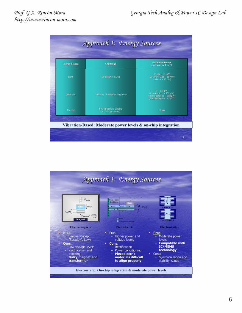
•• Pros:Pros:–– Simple concept Simple concept
(Faraday(Faraday’’s Law)s Law)•• ConsCons::
–– Low voltage levelsLow voltage levels–– Rectification and Rectification and
boostingboosting–– Bulky magnet and Bulky magnet and
transformertransformer
•• Pros:Pros:–– Higher power and Higher power and
voltage levelsvoltage levels•• ConsCons::
–– Rectification Rectification –– Power conditioningPower conditioning–– Piezoelectric Piezoelectric
materials difficult materials difficult to align properlyto align properly
•• ProsPros::–– Moderate power Moderate power
levelslevels–– Compatible with Compatible with
IC/MEMS IC/MEMS technologytechnology
•• Cons:Cons:–– Synchronization and Synchronization and
stability issuesstability issues
Electromagnetic Piezoelectric Electrostatic
Electrostatic: On-chip integration & moderate power levels
FTensile
FCompressive
Mass
VOC(t)+-+-
+
-
V1
V2
Piezoelectric Material
Shim
Piezoelectric Cantilever
Fspring
Fdamping
MotionMass
Magnet
Energy Harvesting
Force
+-
=
Vout(t)
Approach 1: Energy SourcesApproach 1: Energy Sources

6
Prof. G.A. Rincón-Morahttp://www.rincon-mora.com
Georgia Tech Analog & Power IC Design Lab
1111
↑ ↑•• Q = C VQ = C V
•• I = I = dQ/dtdQ/dt = C (= C (∂∂V/V/∂∂t) + V (t) + V (∂∂C/C/∂∂t) t) ≈≈ V (V (∂∂C/C/∂∂t)t)
•• EEHarvestHarvest = 0.5 (= 0.5 (CCMaxMax –– CCMinMin) V) V22
–– If If ∆∆C = 100pF & V = 4V, C = 100pF & V = 4V, EEHarvestHarvest = 800pJ= 800pJ
•• Electrostatic VElectrostatic V--Constrained BasicsConstrained Basics
Pre-Charge and Recovery
VBAT
CMEMS
+
-
IHarvest
(Cmax to Cmin)
+
-VBAT
•• How?How?
–– 1. Pre1. Pre--Charge CCharge CMEMSMEMS
–– 2. Harvest2. Harvest
–– 3. Recover Residual3. Recover Residual
Approach 1: Harvesting CircuitApproach 1: Harvesting Circuit
•• Challenges:Challenges:
SynchronizationSynchronization PrePre--Charge ControlCharge Control
Power Losses (Net Gain)Power Losses (Net Gain) Clock FeedClock Feed--ThroughThrough Charge LeakageCharge Leakage
1212
Approach 2: Extend RuntimeApproach 2: Extend Runtime•• GoalGoal == Extend Operation LifeExtend Operation Life (i.e., battery life or runtime)(i.e., battery life or runtime)
RagoneRagone PlotPlot
ApproachApproach ModeMode--hophop from device to device to from device to device to
extract energy from highest energy devicesextract energy from highest energy devices
(i.e., stay on flat traces)(i.e., stay on flat traces)
* * Fuel CellsFuel Cells: Slow, highest energy at light Loads: Slow, highest energy at light Loads
* * LiLi--IonIon: Faster, highest energy during burst: Faster, highest energy during burst--
peak loadspeak loads
* * CapacitorCapacitor: Fastest, highest energy during high : Fastest, highest energy during high
peak transient (high peak transient (high di/dtdi/dt) loads) loads
* * InductorInductor: Cumbersome & slow but able to : Cumbersome & slow but able to
transfer energy in the form of currenttransfer energy in the form of current

7
Prof. G.A. Rincón-Morahttp://www.rincon-mora.com
Georgia Tech Analog & Power IC Design Lab
1313
Approach 2: Fuel CellsApproach 2: Fuel Cells
•• Fuel Cell (FC)Fuel Cell (FC): Electrochemical energy conversion device: Electrochemical energy conversion device
Fuel (e.g., hydrogen) + Oxidant (e.g., oxygen) Fuel (e.g., hydrogen) + Oxidant (e.g., oxygen) Water + Electricity (e.g., current)Water + Electricity (e.g., current)
•• CategoriesCategories::
Alkaline FC (AFC)Alkaline FC (AFC) Phosphoric Acid FC (PAFC)Phosphoric Acid FC (PAFC)
Molten Carbonate FC (MCFC)Molten Carbonate FC (MCFC) SolidSolid--Oxide FC (SOFC)Oxide FC (SOFC)
ProtonProton--Exchange Membrane FC (PEMFC)Exchange Membrane FC (PEMFC) Direct Methanol FC (DMFC)...Direct Methanol FC (DMFC)...
•• DMFCDMFC is a variant of PEMFC:is a variant of PEMFC:
Extracts hydrogen from liquid methanolExtracts hydrogen from liquid methanol
directly, without the need of a bulky fueldirectly, without the need of a bulky fuel
reformer (necessary in other FC to reformer (necessary in other FC to
transform hydrocarbon fuels into hydrogen).transform hydrocarbon fuels into hydrogen).
Therefore, Therefore,
best suited for miniaturizationbest suited for miniaturization
(40% (40% ηη at 50at 50--130130ººC)C)
Fuel In
++
2 2
Fuel Tank
Fuel
1414
Approach 2: Fuel CellsApproach 2: Fuel Cells
•• DMFC:DMFC:
* Issues: * Issues:
a. Methanol crossover: Fuel leakage/loss across membranea. Methanol crossover: Fuel leakage/loss across membrane
* High temperature, diluted methanol, and exotic electrolytes he* High temperature, diluted methanol, and exotic electrolytes help.lp.
b. Relatively low current ratings (i.e., low power)b. Relatively low current ratings (i.e., low power)
* More concentrated methanol and ultra* More concentrated methanol and ultra--capacitor technologies help.capacitor technologies help.
c. High overc. High over--potentials: Slow electrolyte kinetics (slow response times potentials: Slow electrolyte kinetics (slow response times -- low BWs)low BWs)
* Active catalysts help* Active catalysts help
* Constant fuel* Constant fuel--flow control helpsflow control helps
d. Limited tank size & reduction in fuel concentrationd. Limited tank size & reduction in fuel concentration
* Energy & Power decrease over time* Energy & Power decrease over time
8
Prof. G.A. Rincón-Morahttp://www.rincon-mora.com
Georgia Tech Analog & Power IC Design Lab
1515
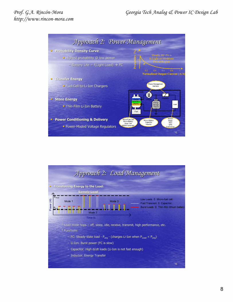
Approach 2: Power ManagementApproach 2: Power Management•• Probability Density CurveProbability Density Curve
•• Highest probability @ low powerHighest probability @ low power
–– Battery Life = Battery Life = f(Lightf(Light Load) Load) FCFC
•• Transfer EnergyTransfer Energy
•• FuelFuel--CellCell--toto--LiLi--Ion ChargersIon Chargers
•• Store EnergyStore Energy
•• ThinThin--Film LiFilm Li--Ion BatteryIon Battery
•• Power Conditioning & DeliveryPower Conditioning & Delivery
•• PowerPower--ModedModed Voltage RegulatorsVoltage Regulators
+
-
Charger Regulator
Fuel
PowerGeneration
Source EnergyStorageDevice
+
-Load
Micro-Fuel CellMicro-Battery
Solar CellMEMS Generator
Micro-BatteryCapacitorInductor
SensorMeterADCGPS
Transceiver
Micro-BatteryCapacitorInductor
Power ManagementInterface
Self-Powered Chip
0.2 0.4 0.6 0.8 1
1
2
3
4
Normalized Output Current [A/A]
Prob
abili
ty [%
]
Mostly, RF PA isin Light-to-Moderate
Power Region
1616
Approach 2: Load Management Approach 2: Load Management
•• Transferring Energy to the Load:Transferring Energy to the Load:
Sample LoadSample Load
* Load mode hops * Load mode hops –– off, sleep, idle, receive, transmit, high performance, etc.off, sleep, idle, receive, transmit, high performance, etc.
* Functions:* Functions:
–– FC: SteadyFC: Steady--state load state load -- PPavgavg -- (charges Li(charges Li--Ion when Ion when PPLoadLoad < < PPavgavg))
–– LiLi--Ion: Burst power (FC is slow)Ion: Burst power (FC is slow)
–– Capacitor: High Capacitor: High di/dtdi/dt loads (Liloads (Li--Ion is not fast enough)Ion is not fast enough)
–– Inductor: Energy TransferInductor: Energy Transfer
Mode 1
Time (t)
P
ower
(W) PPeak
PAvg
Low Loads Micro-fuel cellFast Transient CapacitorBurst Loads Thin-film lithium battery
Mode 2
Mode 3

9
Prof. G.A. Rincón-Morahttp://www.rincon-mora.com
Georgia Tech Analog & Power IC Design Lab
1717
The MicroThe Micro--System: Power ManagementSystem: Power Management
•• Power System:Power System:
** Analog = Noise SensitiveAnalog = Noise Sensitive
DSP DSP ≠≠ Noise SensitiveNoise Sensitive
Dirty/Clean SuppliesDirty/Clean Supplies
* FC supplies DC & * FC supplies DC &
LiLi--Ion supplies Peak BurstsIon supplies Peak Bursts
* FC also charges Li* FC also charges Li--Ion Ion
* Scavenger charges Li* Scavenger charges Li--Ion Ion
* FC/Li* FC/Li--Ion charge LsIon charge Ls
* Ls supply power to load* Ls supply power to load
& charge Cs& charge Cs
* Cs supply transient loads* Cs supply transient loads
* Power Efficient Circuits* Power Efficient Circuits
* Integrated Ls & Cs* Integrated Ls & Cs
MEMS & MultipliersMEMS & Multipliers
* * FC/Scav.FC/Scav.--CompabibleCompabible
CircuitsCircuits
Lx Cx
Buck
Lx
Boos
t
Li-I
on
Fuel
C.
2.7-4.2V
0.9-1.4V
1.8V
CxLDO
1.6V
Load
Load
Lx
Boos
t
Scav
eng.
X
Fuel
Charger
Charger
Noise-FreeSupply
Noisy Supply
Noisy Supply
AnalogLoad
DSPLoad
Chrg Pump
Cx+-
1818
•• Catering to the Load Catering to the Load -- Distributed Supplies:Distributed Supplies: PointPoint--ofof--load (POL) regulationload (POL) regulation
[1] D. Maksimović, “Power, “Management Model and Implementation of Power Management ICs for Next Generation Wireless Applications,” IEEE International Symposium on Circuits and Systems, 2002.
11
CategoriesCategories
* High Power * High Power
(Orange)(Orange)
* Low Power (blue)* Low Power (blue)
* High Accuracy* High Accuracy
* Low Accuracy* Low Accuracy
* Optimized Voltage * Optimized Voltage
LevelsLevels
1. High Power/Low Accuracy DC/DC Converter (↑ η)2. High Power/High Accuracy DC/DC + Linear Regulator 3. Low Power/Low Accuracy Charge Pump3. Low Power/High Accuracy Linear Regulator …
The MicroThe Micro--System: Power ManagementSystem: Power Management

10
Prof. G.A. Rincón-Morahttp://www.rincon-mora.com
Georgia Tech Analog & Power IC Design Lab
1919
The MicroThe Micro--System: Requirements System: Requirements •• SoCSoC Power Management Circuit Requirements:Power Management Circuit Requirements:
* * Fast load dumpsFast load dumps (clock(clock--synchronized events)synchronized events)
SlewSlew--raterate
BWBW
Filter Stages (large L & C)Filter Stages (large L & C)
* * Long Battery LifeLong Battery Life (operation life or runtime)(operation life or runtime)
ηη regulatorsregulators
ηη chargerschargers
PowerPower--modedmoded systemsystem
TimeTime--division multiplexed tasksdivision multiplexed tasks
* * High PerformanceHigh Performance
AccuracyAccuracy
PointPoint--ofof--load (POL) regulation load (POL) regulation -- distributed suppliesdistributed supplies
BWBW monitors (complex control system monitors (complex control system -- FC, LiFC, Li--Ion battery, etc.)Ion battery, etc.)
Voltage circuits (powered from low voltage supplies Voltage circuits (powered from low voltage supplies -- FC ~ 0.7V)FC ~ 0.7V)
2020
The MicroThe Micro--System: IntegrationSystem: Integration
Fuel In
++
p+
2 2
FOXgnd
p+p+p+ n+n+n+p+FOX FOX FOXFOX FOX FOX
gnd
Oxide & Passivation
Hot Surface
N-type SiP-type Si
Plastic Package
Cold Surface
200-
400
mµ
•• SiPSiP Technologies: Technologies: MEMS Devices, CMOS Circuits, & ThinMEMS Devices, CMOS Circuits, & Thin--Film LiFilm Li--Ion BatteryIon Battery
–– Energy SourcesEnergy Sources: : MEMS Thermoelectric/Vibration Generators, & Fuel Cell StackMEMS Thermoelectric/Vibration Generators, & Fuel Cell Stack
–– Energy StorageEnergy Storage: : LiLi--Ion Polymer Battery, Planar Cu Inductors, Ion Polymer Battery, Planar Cu Inductors,
Inductor Multipliers, & Capacitor MultipliersInductor Multipliers, & Capacitor Multipliers
–– Power Conditioning/DeliveryPower Conditioning/Delivery: : Power Efficient CMOS RegulatorsPower Efficient CMOS Regulators
–– Load Conditioning/Energy TransferLoad Conditioning/Energy Transfer:: Low Voltage Power Efficient CMOS ChargersLow Voltage Power Efficient CMOS Chargers

11
Prof. G.A. Rincón-Morahttp://www.rincon-mora.com
Georgia Tech Analog & Power IC Design Lab
2121
The MicroThe Micro--System: IntegrationSystem: IntegrationFlip Chip Fuel Cell/Lithium Ion HybridFlip Chip Fuel Cell/Lithium Ion Hybrid
(p-type Silicon Substrate)p+p+p+ n+n+n+
n-w e llp+ p+
(Oxide)FOX FOX FOXFOX FOX
Metal 1Metal 2
n+n+FOX
n+FOX
Copper Inductor
(Passivation and Plastic Package)
Fuel In
p+p+p+ n+n+n+p+
++
p+
FOXFOX FOX FOXFOX FOX FOXgndgnd
2 2
2222
The MicroThe Micro--System: ChallengesSystem: Challenges•• Package Integration:Package Integration:
* Fuel Cells* Fuel Cells * Energy Scavengers* Energy Scavengers * Planer Cu Inductors* Planer Cu Inductors
* Thin* Thin--Film LiFilm Li--IonIon * Power MEMS Inductors* Power MEMS Inductors * Bulk Capacitors* Bulk Capacitors
* Re* Re--Fueling (unnecessary for disposable applications)Fueling (unnecessary for disposable applications) * Testability* Testability
•• Power Management:Power Management:
* Multiple* Multiple--ChargersChargers--toto--SingleSingle--Battery SystemBattery System * Multiple* Multiple--SourceSource--toto--SingleSingle--Output Output
SupplySupply
* Accurate/Fast System Health Monitors* Accurate/Fast System Health Monitors * Emergency Battery Handoff* Emergency Battery Handoff
•• CMOS/CMOS/BiCMOSBiCMOS Supply Circuits:Supply Circuits:
* Fuel* Fuel--Cell Compatible Boost RegulatorCell Compatible Boost Regulator * Fast Capacitor Multipliers * Fast Capacitor Multipliers
* Efficient, Low* Efficient, Low--Voltage Power SwitchesVoltage Power Switches * Efficient Inductor Multipliers* Efficient Inductor Multipliers
* Scavenger* Scavenger--Compatible Intermittent Trickle Boost ChargerCompatible Intermittent Trickle Boost Charger
* Fuel* Fuel--Cell Compatible Boost ChargerCell Compatible Boost Charger
* Safe Mode* Safe Mode--Hop Manager and PM BrainHop Manager and PM Brain
* * ……

12
Prof. G.A. Rincón-Morahttp://www.rincon-mora.com
Georgia Tech Analog & Power IC Design Lab
2323
The Future, RevisitedThe Future, Revisited……
•• The MeansThe Means::
•• The GoalThe Goal::
-- End End --
•• The RoadThe Road:: Design Bridges Design Bridges →→ SiP/SoP/SoCSiP/SoP/SoC
Product/Market/Process/Device/Circuit/Product/Market/Process/Device/Circuit/
System/IC/Package/PCB/ApplicationSystem/IC/Package/PCB/Application
Technology Leaps Technology Leaps →→ Robust, Low V, Low Robust, Low V, Low IIinin, High , High IIoutout, High , High PerfPerf. .
MixedMixed--Signal ICs Signal ICs →→ Integration Integration of Power Passives, Batteries of Power Passives, Batteries
(fuel cells, Li(fuel cells, Li--ion)ion)……
Portable, SelfPortable, Self--Powered, SelfPowered, Self--SustainingSustaining, Battery, Battery--Operated,Operated,
SystemSystem--onon--Package (Package (SoPSoP) Solutions) Solutions