The Marconi Review - americanradiohistory.com · "MARCONI REVIEW" BINDERS Orders for loose-leaf...
51
P'171 R The Marconi Review No. 98 3rd QUARFER 1950 Vol. XIII CONTENTS: The Computation of Great Circle Bearings and Distances - 89 The Effect of Rain on Marine Radar Echoes - ioz Boo,k, Review - 109 A S et for Noise and Distortion Tests on Carrier and Broadcast Systems - 110 News and Notes - 130 MARCONI'S WIRELESS TELEGRAPH COMPANY LIMITED Head Office, Marconi House, Chelmsford Telephone, Chelmsford 3221 Telegraphic Address, Erpcusse, Chelmsford
Transcript of The Marconi Review - americanradiohistory.com · "MARCONI REVIEW" BINDERS Orders for loose-leaf...

P'171 R
The
Marconi ReviewNo. 98 3rd QUARFER 1950 Vol. XIII
CONTENTS:
The Computation of Great Circle Bearings and Distances - 89
The Effect of Rain on Marine Radar Echoes - ioz
Boo,k, Review - 109
A S et for Noise and Distortion Tests on Carrier and Broadcast Systems - 110
News and Notes - 130
MARCONI'S WIRELESS TELEGRAPH COMPANY LIMITEDHead Office, Marconi House, Chelmsford Telephone, Chelmsford 3221 Telegraphic Address, Erpcusse, Chelmsford

THE MARCONI GROUP OF COMPANIESIN GREAT BRITAIN
Registered Office : Electra House,Victoria Embankment,London, W.C.2.
Telephone : Temple Bar 4321.
MARCONI'S WIRELESS TELEGRAPH COMPANY, LIMITEDMarconi House, Telephone : Chelmsford 3221.Chelmsford, Telegrams : Expanse, Chelmsford.Essex.
THE MARCONI INTERNATIONAL MARINE COMMUNICATION COMPANY, LIMITEDMarconi House, Telephone : Chelmsford 3221.Chelmsford, Telegrams : Thulium, Chelmsford.Essex.
THE MARCONI SOUNDING DEVICE COMPANY, LIMITEDMarconi House,Chelmsford,Essex.
Telephone : Chelmsford 3221.Telegrams : Thulium, Chelmsford.
THE RADIO COMMUNICATION COMPANY, LIMITEDMarconi House, Telephone : Chelmsford 3221.Chelmsford, Telegrams : Thulium, Chelmsford.Essex.
THE MARCONI INTERNATIONAL CODE COMPANY, LIMITEDMarconi House, Telephone : Chelmsford 3221.Chelmsford, Telegrams : Thulium, Chelmsford.Essex.
MARCONI INSTRUMENTS, LIMITEDSt. Albans, Telephone : St. Albans 6161/5.Hertfordshire. Telegrams : Measurtest, St. Albans.

"MARCONI REVIEW" BINDERS
Orders for loose-leaf covers for copies of the "Marconi Review'' for 1951-1953
similar to those supplied for 1948-1950 can now be accepted. Each cover will
hold 12 issues and will cost 7/6d. Will those who would like to acquire this binder
please fill in and return the attached form with a cheque or postal order for the
appropriate amount.
Please reserve for me copies of the " Marconi Review " Binder 1951-1953
at 7 6d. each, for which I enclose the sum of
(Name)
(Address)
Date

THE MARCONI GROUP OF COMPANIESIN GREAT BRITAIN
Registered Office : Electra House,Victoria Embankment,London, W.C.2.
Telephone : Temple Bar 4321.
MARCONI'S WIRELESS TELEGRAPH COMPANY, LIMITEDMarconi House, Telephone : Chelmsford 3221.Chelmsford, Telegrams : Expanse, Chelmsford.Essex.
THE MARCONI INTERNATIONAL MARINE COMMUNICATION COMPANY, LIMITEDMarconi House, Telephone : Chelmsford 3221.Chelmsford, Telegrams : Thulium, Chelmsford.Essex.
THE MARCONI SOUNDING DEVIMarconi House,Chelmsford,Essex.
E COMPANY, LIMITEDTelephone : Chelmsford 3221.Telegrams : Thulium, Chelmsford.
THE RADIO COMMUNICATION COMPANY, LIMITEDMarconi House, Telephone : Chelmsford 3221.Chelmsford, Telegrams : Thulium, Chelmsford.Essex.
THE MARCONI INTERNATIONAL CODE COMPANY, LIMITEDMarconi House, Telephone : Chelmsford 3221.Chelmsford, Telegrams : Thulium, Chelmsford.Essex.
MARCONI INSTRUMENTS, LIMITEDSt. Albans, Telephone : St. Albans 6161/5.Hertfordshire. Telegrams : Measurtest, St. Albans.

THE MARCONI R FiVi FiWNo. 98. 3rd Quarter, '910.
Editor L. E. Q. WALKER, A.R.C.S.
The copyright of all articles appearing in this issue is reserved by the - Marconi Review.' Application f..r permi,sion toreproduce them in whole or in part should be made to Marconi's Wireless Telegraph Company Ltd
THE COMPUTATION OF GREAT CIRCLEBEARINGS AND DISTANCES
BY G. MILLINGTON, M.A., B.Sc.,
The standard formulce for the computation of great circle bearings and distancesare subject to small difference difficulties necessitating under some conditions the use ofseven figure logarithms to obtain four figure accuracy. This trouble is overcome bytrigonometrical transformations, so that the accuracy of the tables does not need to behigher than that of the final answer.
At the same time, the rule of signs associated with the formula is simplified andembodied in a standard table used for the computation of any given case. It is shownthat the transformed equations degenerate directly to the simple projection formula, forshort distances where the effect of the earth's curvature is negligible.
Introduction.
TO THE engineer who is concerned with the erection of beam aerial arrays, orwho is engaged on wireless direction finding work, the problem of thecomputation of great circle bearings is of special importance. The research
engineer is also interested in the determination of great circle distances, when forinstance, he seeks to interpet long distance transmission phenomena in terms ofreflections from the ionosphere at oblique incidence.
Standard methods are in use for making such computations, but in general, theyare cumbersome to use, and they involve conventions and rules of signs which areapt to be confusing. It was felt, therefore, that it would be useful to discuss thegeneral aspects of the problem, and to suggest a modified procedure which, it is hoped,will be found to be free from some of the disadvantages of the existing methods.
Any method of computing great circle data which is exact, and not merely anapproximation applicable, say, to short distances, must involve the use of thefundamental formula, of spherical trigonometry. The really remarkable extent towhich these formula, lend themselves to transformation is very helpful, since itenables one to choose a form which is most suitable to the purpose in hand.Inspection of the problem shows that most of the disadvantages of the existing
A ( 89 )

The Computation of Great Circle Bearings and Distances
methods can be removed by adopting alternative transformations of the fundamentalformulae.
In discussing these disadvantages and the proposed modifications, it will be usefulto state the features to be desired, namely, that the method should be straightforwardand applicable to the most general cases, including short distance routes, and thatthe necessary rules of signs should be reduced to a simple self-explanatory scheme,involving no conventions that will lead to possible confusion, or imply a preliminaryinvestigation of the type to which any particular case may belong.
The Accuracy required in Practice.In considering the accuracy to which the great circle bearing must be computed,
we can say that it will be sufficient to give the angle to one or two minutes of arc ;but it is important to notice that this accuracy is required whatever the numericalvalue of the angle measured E. of N. This is obvious when we consider that adirection finder is really only concerned with the limits within which it can definethe direction of arrival of a wave, and that these limits are independent of thearbitrary datum, the great circle through the north pole, from which we choose tomeasure the direction.
On the other hand, when we are dealing with great circle distances, and theseare expressed in terms of angles subtended at the centre of the earth, we areconcerned with percentage accuracy, and we must interpret our formula accordingly.If, for instance, we have a short distance which is only 1° in angular measure, i.e.,111.1 kilometres, we must measure this angle to within 3.6 seconds if we wish toexpress the distance to 1 part in 1,000, i.e., to within 100 m. It is, therefore, necessaryto remember that the accuracy of the final answer, expressed as an angle, has to beinterpreted differently, according as the angle refers to a great circle bearing or adistance.
The accuracy for the distance measurement suggested above, i.e., 1 part in 1,000,may be taken as sufficient for all likely requirements. As we have seen, this meansthat for short distances we must know the equivalent angles to within fractions of asecond of arc, e.g., a distance of 1 km. measured to an accuracy of 1 m. implies anangle of 32.40 seconds measured to within 0.03 seconds. In practice, of course, suchshort distance routes are usually measured on a map or on a gnomonic chart, but itis useful to be able to include them within the scope of a standard method.
The working out of the bearings and distances to the accuracy suggested implies,naturally, that the initial data will warrant it. For instance, for a short distanceroute we must be given the differences of latitude and longitude involved to within,perhaps, a fraction of a second of arc, even though the absolute values of the latitudeand longitude at each end may not be accurate to several minutes of arc. But in allcases the proposed accuracy should be within the scope of four figure logarithmtables, and it should be one of our aims to devise a method in which four figuretables only need be used throughout the working to ensure the desired accuracy inthe final results.
Now it is well known that seven figure logarithms have often to be employedto obtain only four figure accuracy, due to the inconvenient form of the formulaeused under certain conditions, and indeed it is usual to use them in all cases, eventhough four figure logarithms would be adequate in the majority of cases. Thisinevitably makes the process cumbersome, since the use of seven figure logarithmsinvolves much page turning and large difference values. Apart from the question
( 90 )
The Computation of Great Circle Bearings and Distances
of the labour entailed, it would seem to be more logical to use a method in which fourfigure logarithms can be made to give in all cases the required accuracy.
The difficulty arises from the fact that the usual forms express the functions ofthe angles required as the difference between two terms, which may be very smallwhen the separate terms themselves are very large. One method of overcoming thisdifficulty is to transform the formula so that they involve only products. Such ascheme is outlined in Keen's book on " Wireless Direction Finding " (cf. pp. 990-992of the fourth edition). But this scheme inter -relates the calculations of the anglesand distances, and involves conventions (such as that B shall be the place of greaterlatitude) which may lead to confusion, while considerable care is needed in handlingthe equations in certain limiting cases. It is interesting to notice that in the examplegiven, the six figure logarithms used are only necessary in so far as the bearings arecalculated to 0.5 minutes of arc.
Conventions and Rules of Signs.Before proceeding to propose an alternative scheme, we will briefly discuss the
question of conventions and rules of signs. The necessity for these really arisesfrom the fact that the various trigonometric functions are positive or negative invalue according to the quadrant in which the angle happens to be. To avoid havingto remember the rules deciding the signs of these functions, it is desirable to evolvea new set of rules and conventions especially adapted to the problem in hand, and -embracing all possible cases. The various cases are necessitated by considerationof whether the two places are both in the same hemisphere or in opposite liemi-spheres, and whether the difference of longitude is less or greater than 90°, andfinally, whether the bearing is less or greater than 90° E. (or W.) of N. These
possible types still involving furtherconventions common to them all.
The ideal would be to make the rules self-explanatory by embodying them as partof the actual process, so that the necessary signs are obtained when wanted by alogical deduction as the work proceeds. We shall seek, therefore, to present theworking in a tabular form, so that one has only to fill the table in according to astandard routine, and to include the necessary instructions in the table itself, withoutneed to refer to any separate description of the process.
The Fundamental Formulae and Transformations.We come now to the discussion of the fundamental formula upon which our
modifications are to be based. They are essentially derived from the solution of aspherical triangle, two points of which are the places under consideration, while thethird point is one or other of the poles. We are, therefore, really concerned with theco -latitudes of the two places, i.e., the angles measured not from the equator butfrom one of the poles. We notice that we should measure these angles from thesame pole, even when the places are in different hemispheres, and this suggests thatour first convention should be to work from the same pole under all conditions, andwe choose this to be the north pole. Thus we keep to this rule even when bothplaces are in the southern hemisphere. But since we normally think in terms oflatitude, rather than co -latitude, we must transform our formula accordingly, andit will be seen that our convention simply reduces to the rule that under allconditions latitudes in the northern hemisphere are to be reckoned positive, andthose in the southern hemisphere negative.
( 91 )

The Computation of Great Circle Bearings and Distances
A further obvious convention is that we should always compute the shortroute, i.e., the great circle arc joining the two places which is less than 180°. Thisis equivalent to the convention that the difference of longitude should be taken asless than 180°. This naturally decides whether the one place is to be consideredE. or W. of the other, and the formula will then give the bearing in terms of anangle E. or W. of N.
With these conventions in mind, we use the following notation :-(1) The two places are called A and B.(2) The latitudes of A and B are LA and LB respectively.(3) The difference of longitude is D.(4) The bearing of B measured at A is OA, E. or W. of N.(5) The bearing of A measured at B is OB, E. or W. of N.(6) The distance between A and B is d measured in degrees.
We can now state the fundamental formula for OA and d, which are asfollows :-
cot OA = cos LA tan LB cosec D - sin LA cot Dcos d = cos LA cos LB cos D + sin LA sin LB
To obtain cot OB we merely interchange the suffixes A and B in (1).
We can see at once from (1) that confusion may arise with regard to the signsof the two terms composing the expression for cot OA, since when LA or LB changessign, the sine and the tangent functions also change sign but the cosine does not.Also when D is greater than 90° the cotangent becomes negative while the cosecantremains positive. When D is very small, cosec D and cot D are both very large, andshould the bearing be nearly 90° E. or W. of N., cot OA will be very small, and in thiscase the small value of cot OA will have to be determined as the difference of two verylarge terms (unless, of course, either place happens to be very near to the equator,when sin LA and tan LB will be very small). This difficulty is the one which has beenreferred to above, which necessitates the use of seven figure logarithms to obtainfour figure accuracy, for which they may even be inadequate in extreme cases.
This is the major objection to the use of the form for cot OA given in (1), whichwe must try to remove by some convenient transformation, but at the same time wewill aim at simplifying the rule of signs involved, and at making the expression moresymmetrical than that in (1). The clue to our problem is found in convertingcosec D and cot D into functions of D/2, which will remove the change of sign whichoccurs when D becomes greater than 90°. The required relations are :-
[cotP2cot D .=--- i [cot 1_ tan Di
2cosec D = i + tan P2
1Also if we take2 cos LB outside as a factor of the expression in (1), we have
inside terms of 2 cos LA sin LB and 2 sin LA cos LB which can be written assin (LA + LB) - sin (LA - LB) and sin (LA + LB) + sin (LA - LB) respectively.
On making these substitutions and re -arranging, we have
cot OA - 1 D2 cos
LB[sin (LA + LB) . tan - sin (LA - LB)]2 tan D/2
( 92 )
(1)
(2)
(3)

The Computation of Great Circle Bearings and Distances
where we have replaced cot by tan1D/2 since we then have only a single function o
D to consider, involving only one logarithm to be looked up in the tables.Now if we interchange the suffixes B and A wo have after a slight re -arrangement,
cot OB1 sin (LA - LB) .1
(4)[sin (LA + LB) . tan D2 cos LA 2 tan D/2
and we see at once that (3) and (4) can be written in the form
cot OA = 1 [X - Yl (5)2 cos LBand
cot OB =1cosG L A PC + Yl (6)
where X = sin (LA + LB) . tan D/2 (7) and Y = sin (LA - LB)/tanD/2 (8)
We have thus obtained a degree of symmetry which was not apparent in (1),and although we can use the method to determine BA or BB independently, when wehave found one, we have already performed most of the computation necessary tofind the other. It is not difficult to make use of this connection between cot OA andcot OB to inter -relate the values of OA and BB, and obtain the formula used by Keenand referred to above.
At first sight it may appear that we have not removed the difficulty arising fromthe fact that our expression still involves the difference of two terms which may benearly equal. But we see from (7) and (8) that since the factor tan D/2 appearsin the numerator of X and in the denominator of Y, when X is large (which it canonly be by tan D/2 becoming large) Y must be small, and similarly if tan D/2 is small,so that Y can be large, X must be small. Thus X and Y cannot be large together,and it therefore follows that when X and Y are nearly equal, and X -Y or X + Ymay be very small, they must both be reasonably small. It is not difficult to seethat even in the most extreme cases, our transformation has removed the objection,and that the angle BA or BB can be evaluated to within the stipulated limits of 1 or2 minutes of arc.
Considering now the signs of the terms X and Y, the factor tan D/2 is alwayspositive, since by convention D is less than 180°. The signs of X and Y aretherefore simply the signs of sin (LA + LB) and sin (LA - LB) respectively, andsince LA + LB and LA - LB must both be numerically less than 180°, and the sineof an angle changes sign with the angle, it follows that the signs of X and Y are thoseof LA + LB and LA - LB respectively. Having thus determined the signs ofX and Y, we see from (5) and (6) that the signs of cot BA and cot OB are those ofX -Y and X + Y respectively, since cos LA and cos LB are positive independentlyof the signs of LA and LB, as these angles are numerically less than 90°.
If the sign of cot OA is positive, it means that OA measured E. or W. of N. is lessthan 90°, while if the sign is negative, OA is greater than 90°. Now in practice weshall obtain the value of BA from a computed value of log cot OA by looking up theappropriate table, and, disregarding the sign of X - Y, this will yield an angle whichis less than 90°. It is therefore simpler at this stage to modify our definition of OA,
( 93 )

The Computation of Great Circle Bearings and Distances
TABLE I6A = Bearing of B from A 68 = Bearing of A from B d = Angular Distance
Place Latitude Longitude
DiffereRceD <-180
A --
B =
L =A
LB .
H. Latitudes + VE
S. Latitudes - VE
LA + LB .
LA - LB =
D =
_D- -2
Li ( <90°) = ILA + LB 1
or 1800 - I LA + LB I
.
Log sin Lx =
+ Log tanD
=
Ly (<90°) = ILA - LB!
or 180° -ILA - LB
.
Log sin Ly =
- Log tanD-
Log X = Log Y =
X has the sign of LA + LB
I =
Y =
Y has the sign of LA - LB
Y =
X .
1 -I = X + Y =
I It -I I_
X - Y I
1X+2YI
+Log =
1 2
- Log oos LB =
Log--FI-11X
- Log cos LA
=
=
Log cot ex = Log cot 88 =
0A (<90°) =
For D <180°, a ill : of AN
I - I' is + .'. eA is measured from
E Hof
= E of N
68 (<90°) .
For D <180°, A is E of BNX + Y is + .. 8B is measured from
E Nof
= E of N
LA + LB LA - Lid
Lm +
I 2
45° =
-
(to nearest degree)
I
I'li +
2
D=
(to nearest degree)
Lm + 45° Lm + Y. .. Use It:f alternatives tnroughout
Log cs°1 Lm =
+ Log sinD
=
Logsin
Lm =
+ Log cosD
=
Log M - Log N =
Log M2 = 2 Log M =
m2
112 =
Log N2 = 2 Log N =
82
d
decimals) =x 111.1) =
(degrees)
x 69.1) =kilometres)
x 60.0) = (nautical miles)
K2 + =112
2 Log :ions. t . Log (M2 + N2) =
L°
sin=g
d
2
( 94 )

J
The Computation of Great Circle Bearings and Distances
TABLE IIOA = Bearing of B from A OB = Bearing of A from B d = Angular Dietance
Place Latitude Longitude
Utterer.D <180
A = BADDON
B = ONGAB
LA '= 51° 42 20" N
LB = 51° 42' 47" N
oo ,,' 3."J.
00l',
10 47 E
N. Latitudes + VE
S. Latitudes -VE
LA + LB = 103°25, 7,,,
LA - LB = - 0° 0' 27"
D = 0° 19' 28
1-21 = 0° 9' 44"
Lx (<90°) . I LA + LB I
or 180° - ILA + LB I
= 76° 34' 53"
Log sin 11 = 1.9880+ Log tan 11D= 3.4519
1"f (<90°) = ILA - LB 1
or 180° -ILA - LB'
= 0o 0' 27"
Log sin L... = 4.11701
- Log tan - = 3.4519
Log X = 3.4399 Log Y = 2.6651
X has the sign of LA + LB
X = 0.002754
Y = - 0.04625
Thee the sign of LA - LB
r = - 0.04625X = 0.002754
-_---
X - Y = 0.04900 X + Y = - 0.04350
Y P 1 = 0.02175
2.3375
IX= 0.02450
1-=-I1,3892
1
I X-2---.YILog!2 I =
- Log cos LB = 1.7920
Log =2
- Log cos LB = 1.7922
Log cot eA = 2.5972 Log cot eB - 2..5433
8 ((90°) = 87° 44'A
For D <180°, B is rt of AN
X - I is + .. eA is measured from
ie N... 0A = 87° 44 w of
= 272° 16' 8 of N
eB (< 90°) = 87° 59'
For D <leo°, A is of B
X + Y is le eB is measured from*sE .I.
59 of s... 0B = 87o' .
= 92° l' E of N
LA + LBI= 510 43,
degree)
Lx =I LA - LB 1 = 0° 0' 13.5*
degree)
I 2
Lm + 45° = 97° (to nearest
2 I
Lti + 2 = 0° (to nearest
Lm + 45° ii, Ls + .*. Use upper alternPtiveethroughout
Log C°3 Lm - 1.7920
+ Log sin 3 = 3.4519
Log ° Ls = 5.8160
+ Log cosD- = 0.00002
Log M = 3.2439 " Log N = 5.8160
Log N2 = 2 Log M = Z.4878
m2 = 3.075 x 10⁻⁶
N2 = 4.285 x 10⁻⁹
Log N2 = 2 Log N = 9.6320
112 = 4.285 x 10⁻⁹
d =
(decimals) = 0.2012 (degrees)( x 111.1) = 22.35 (kilometres)
( x 69.1) = 13.90 (miles)
( x 60.0) = 12.07 (nautical miles)
-6M2 + N2 = 3.079 x 10
2 Logsin4
= Loa (N2 + N2) = Z..4884«s 2 -
Log sin t = 3.2442
d2
= 0.1006°
( 95 )

The Computation of Great Circle Bearings and Distances
and to say that it is an angle less than 90°, which is measured from N. or S. accordingas X -Y is positive or negative. A similar definition can now be adopted for GBwith respect to X + Y. In this way the computation determines an angle lessthan 90°, and a simple and rigid rule of signs tells at once whether the angle is to bereckoned with respect to N. or S., the question as to whether it is E. or W. havingalready been decided in defining the difference of longitude D to be less than 180°.The bearing can then be immediately converted to a standard E. of N.
This scheme obviously lends itself to a simple tabular presentation, and it isproposed to set the process out as in the upper part of Table I. This table is meantto be self-explanatory, in that it contains all the necessary rules as part of theprocess, and an engineer should be able to use it, who is at all conversant with theproblem of computing bearings, without reference to any other description, andwithout previous knowledge of the formula on which the method is based. It willbe seen that the table employs a system of alternatives, in which those which do notapply are crossed out by a logical deduction as the work proceeds, as shown in theexample in Table II.
In the computation of the numerical values of X and Y by means oflogarithms we have written I X I and I Y I from (7) and (8) in the forms
X I = sin Lx . tan D/2 and I Y I = sin Lr /tan D/2
where Lx and Ly are positive angles less than 90°, which are given by I LA + LBand I LA - LB I respectively when these angles are less than 90°, and by180°- I LA ± LB I and 180°- ILA-LaI when I LA ± LB I and ILA-LaI aregreater than 90°. These definitions of Lx and Ly are clearly indicated in the table.
The lower part of the table refers to the computation of the distance d, and todevelop the method upon which it is based we return to a consideration of theexpression for cos d in (2). In this form there is similarly a likely confusion in thesigns, and we seek to remove this disadvantage and to make the formula moresymmetrical. We shall proceed to convert cos D into functions of D/2, andsimilarly to express the formula for d/2 instead of d, but first we notice that cos d isan unsuitable function for determining d when the angle is small, since it approachesunity and is very insensitive to changes of d in this region. We therefore replace
cos d by 1 -2 sin2-d'
and then (2) can be transformed into an equation for sin2_d2 2'
namely
(LA LB) sin2 D (LA - LBsin2d = cos2 + sin2. cos22 2 2 2
which may be writtend = M2 ± N2
where M = cos L.14 sin D/2
and N = sin LN cos DI2
LA + La1in which2
c ( 96 )
(9)
(10)

The Computation of Great Circle Bearings and Distances
andILA - LBI
LN2
Lill and LN are both positive angles less than 90°, and M and N are both positive.dSin-d is also positive, and is by definition less than 90°. We do not therefore need
2any rule of signs, except of course that implied in our convention concerning thesigns of LA and LB which enters into the determination of the values of Las and LN.
There is one slight drawback in formula (9) as it stands, which is that as d
approaches 180°, sin approaches unity and is insensitive to changes in d. This effect
is not so serious as the similar effect in cos d when d is small, but it involves a possibleerror in determining d which may be as great as 1%, and is outside our stipulatedlimits of accuracy. We can overcome this difficulty by converting (9) into an
analogous expression for cost instead of sine for use when the distance becomes2
large. The required formula is
cost d =sine (LA ± LB sine D + cos'cos2(LA - LB. (12)
2 2 2
This may also be written as M2 + N2 provided we now define M and N, instead of by(10) and (11), by
M = sin LM sin and N = cos LN cos
It would be cumbersome to have to use two different formula according as thedistance is small or large, except that the similarity of form between (9) and (12)admits of the two equations being combined as follows :-
sine d m2 + Nzcost 2
coswhere M -=
sinLM sinD and N = scin
LN coscos
where we choose either the upper or the lower alternatives throughout. The workingcan therefore be set out as in the lower part of Table I, and we need a simple criterionfor deciding which alternative to use.
dThe two formulae become equivalent in accuracy when d 90°, i.e., 45°.
The simplest accurate expression for d = 90° is obtained by putting cos d = 0 in (2),which gives cos D = - tan LA tan LB, where we must take account of the signs ofLA and LB, but obviously this is not a convenient criterion to have to apply. On
dthe other hand it would be too vague to say that we use the sine form when the
distance is obviously smaller than 90°, and the cost form when the distance is
obviously greater than 90°, especially if we were to estimate the rough value of thedistance on a Mercator projection with its large distortion of the higher latitudes.
( 97 )
(1

The Computation of Great Circle Bearings and Distances
But fortunately we can make a compromise by using a very simple rule, which isexact for certain conditions, and can be shown to give the dividing line within+13° of 45° for
2for all cases. As the accuracy of either formula varies only
slightly within this range, this rule can therefore be adopted, and it is simply that we
use the sine or the cost2
form according as LM + 45° is greater or less
than LN In applying this rule we need, of course, only express these angles
to the nearest degree, and thus it can be very easily introduced into the scheme, ashas been done in Table I.
The application of this rule involves practically no labour, and as it enablesone to maintain the desired accuracy of computation even on the longest routes, itis well worth while including this slight complication of the process. It falls intoline with the method of presenting the rules of signs as a system of alternativesadopted in the upper part of Table I, and it is intended that likewise the schemeshould be self-explanatory to the engineer who may not be conversant with thereasoning upon which it is based.
Procedure when Certain Angles are Less than 3° or Greater than 87°.In the course of the work it may be found that the logarithm cannot be looked
up accurately in the four figure tables because of the large differences involved. Itmay conversely be found that when the logarithm has been computed, the anglecannot be accurately deduced from it by means of the tables. These cases occurfor the sine, tangent and cotangent functions when the angle is less than 3°, and forthe cosine, tangent and cotangent functions when the angle is greater than 87°.
This at first sight implies a limitation on the method, but it is only in the readingof the tables, and not in the use of the four figure logarithms as such. The accuracyrequired is still only to four figures, and within the scope of four figure logarithms.We need, therefore, a method of obtaining or interpreting the four figure logarithmsaccurately in these cases, and we can find a solution of the difficulty in the fact thatfor a small angle the sine and tangent approximate to the value of the angle itselfmeasured in radians.
If an angle measured in degrees is x, we have, when x is small,TC . Xsin x = tan x =180 57.30
so thatloge sin x = logio tan x = logio x - 1.7581
The value of log sin x so obtained is only two units too big in the last figure of thefour figure logarithm, and the value of log tan x four units too small, when x is 3°,and the approximation rapidly improves as x decreases. We can, therefore, use thisapproximation for all cases when x is less than 3°. By using the relations
cos (90°- x) = sin x and cot (90°- x) = tan x = 1/cot xwe can enlarge our rule to obtain similar approximations for.all the functions whichneed special treatment when x is less than 3° or greater than 87°.
( 98 )

The Computation of Great Circle Bearings and Distances
In Table III are given the functions of this type which may occur in the useof Table I, together with the appropriate formulae for their computation, in whichthe angle is expressed in decimals of a degree.
TABLE III.(a) When x < 3° :
(1) Given x, to find log sin x.(2) Given x, to find log tan x.(3) Given log cot x, to find x.(4) Given log sin x, to find x.
(b) When x > 87° :(1) Given x, to find log tan x.(2) Given x, to find log cos x.(3) Given log cot x, to find x.(4) Given log cos x, to find x.
log sin x = log x - 1.7581.log tan x = log x - 1.7581.log x = 1.7581 - log cot x:log x = log sin x + 1.7581.
log tan x = 1.7581 - log (90°- x).log cos x = log (90°- x) - 1.7581.log (90°- x) = log cot x + 1.7581.log (90°- x) = log cos x + 1.7581.
As an alternative method, it may be preferable to use a special four figure tablecalculated for angles near to 0° and 90° with a fine interval where available. It mayalso be desirable to work throughout in decimals of a degree and to use tables thathave been tabulated in this way. These are, however, matters of detail which donot affect the process as a whole. In any case, an apprenticeship will be needed tohandle it fluently and the computor must decide for himself the precise techniquehe adopts.
As an example, Table II shows the process worked out for the short distanceroute between the Marconi Research Laboratories at Great Baddow, and the OngarWireless Station of Cable & Wireless, Ltd. It will be seen that there are severalplaces where recourse has been made to Table III. We notice especially that the
final value of -is of the order of 6 minutes of arc and we are justified in interpreting
dthe angle to within 0.3 seconds of arc from the computed value of log sin .
Comparison with Approximate Short Distance Formul.Stress has been laid on the applicability of the method outlined above to all
possible cases, including those which usually present special difficulties. Such casesare :-
(1) when the places are near to one another ;(2) when they are antipodal, and(3) when they are in the polar regions.
All these cases repay a careful examination to convince one of the generality of themethod, but it will be interesting to consider here the first one, which is the one ofmost practical importance.
When the two points A and B are close together, to obtain an accurate com-putation of the bearings and the distance we need to know the difference of latitudeand the difference of longitude to the required accuracy, however small the absolutevalues in degrees may be, and, of course, any method of computation assumes thathis necessary information is given. But we see at once the advantage of a formulawhich explicitly involves the angle LA - LB and the sum of the latitudes LA + LB,
( 99 )

The Computation of Great Circle Bearings and Distances
when we have to know the difference of latitude to a fraction of I second of arcwhile we may not know either latitude itself to closer than 1 minute of arc.
Consider now in Fig. 1 a map showing A and B in close proximity, where forconvenience we have chosen them to be in the northern hemisphere, and A to befurther N. than B and to the west of it. The point C represents the intersection of theline of latitude through B with the line of longitude through A, and C' the inter-section of the line of latitude through A with the line of longitude through B.
In this approximate projection picture, the lines all become straight, and anglesACB and AC'B are nearly right angles. The bearings OA and OB, considered asangles less than 90°, are given by Z_ CAB and / C'BA respectively. If r0 is the radiusof the earth, and we consider the angles to be measured in radians, we have :-
AC = BC' = ro (LA - LB), BC = ro D cos LB, AC' = ro D cos LA, AB = rod.
AC LA - LBThus cot BA = =BC D cos LB
and cot VI = BC' LA - LBAC'- D cos LA
(13)
(14)
AB2 is greater than AC'2 BC'2, i.e., r02 I D2 cos2 LA ± (LA - LB)2 , and is less than
BC2 + AC2, i.e., r02 [D2 cos2 LB + (LA - LB)2 , and so we may write as a close
approximation,
AB2 = r02 [D2 cos2 (LA 4- LB) (LA - LB)2]2
or if d is measured in radians,
d2 = D2 cos2 (LA +2 LB) + (LA - LB)2 (15)
D DNow if in (3) were place tan by -, and sin (LA - LB) by LA - LB, weobtain
cot 0 = D sin (LA + LB) LA - LB4 cos LB D cos LB (16)
Now since LA - LB and D are both small, the second term of (16) usuallypredominates over the first term, and this second term is identical with (13). (Thenegative sign indicates that the angle is measured from S. instead of from N., agreeingwith Fig. 1). Similarly, we can compare (4) with (14). When the points A and Bhappen to be on the same latitude, the first term of (16) represents the small angle bywhich the great circle path joining A and B diverges from the line of latitude atA and B, as is represented diagrammatically in Fig. 2. This term becomes zerowhen both points are on the equator, and the line of latitude becomes a great circle.
( 100 )

The Computation of Great Circle Bearings and Distances
TO N POLE
A
C
LONGITUDETHROUGH A
FIG. I
TO N POLE
LATITUDEC' THROUGH A
B LATITUDETHROUGH B
LONGITUDETHROUGH B
GREAT CIRCLE ARC
A LINE OF LATITUDE
FIG, 2
B
Turning now to (9), which is the distance formula suitable for computing shortdistances, and putting
- -sin d = d'-2 2
sin D - sin (LA2
LB LA
2LB
2and cos - = 1,
2 2D
we have, on multiplying through by 4,
d2 = D2 cos2 (LA LB) (LA -L B)22
which is identical with (15).
Thus we see that the foi ins of exact formula which we have developed degeneratedirectly into the simple projection folniulae as A and B approach one another. Inpractice, if one is dealing wholly with short distances, one would use a map, orcompute from the simple projection formul, but in general it is better to use theaccurate foimulx, if there is any doubt as to the error involved in using the pro-jection formula. We have seen from the worked out example given in Table II thatthe standard method is quite easy to use with short distances, and in this case thecorrection due to the first term in (16) is just noticeable.
In conclusion, it may be emphasised that as the form of the equations whichwe have used is exact, since they are obtained by a rigid transformation from thestandard formula, they are not restricted to the four figure accuracy with which wehave been mainly concerned. They are equally applicable, with the use ofcorrespondingly more accurate tables, where higher accuracy is required than isusually envisaged in direction finding work of the kind considered in the introduction.It must be remembered, however, that in such cases, e.g., in the use of high precisionnavigational aids of the type such as " GEE " and " OBOE", account may haveto be taken of the fact that the earth is not a perfect sphere. It should be possible,however, to obtain the necessary modification by means of a correction term appliedto the equations in the form in which we have used them.
( 101 )

THE EFFECT OF
RAIN ON MARINE RADAR ECHOES.BY S. E. BARDEN, B.Sc.
There have been occasions when targets in the vicinity of a ship carrying P.P.I.type radar gear, have remained undetected by the radar operator when heavy rain hasbeen falling. Such a failure of the radar system is explained and analysed below, anda set of curves prepared -to assist the operator to determine--the-ranges within which targetechoes ought to be visible.
IT HAS been known for some time that rain both reflects and attenuates radarmicrowaves. The former effect results in a spread of echoes on the P.P.I.screen, increasing in brightness with intensity of the rainfall, measured in
millimetres per hour. The latter effect decreases the intensity of target echoes, byboth scattering and absorption. Attenuation also increases with the intensity ofthe rainfall. Both these effects limit the ranges of targets below the free spacevalue, and are treated separately below.
Consider first microwave reflections from rainfall, neglecting the attenuationfor the time being. We shall define the equivalent echoing area A of a targetas the projected area of a perfectly reflecting sphere which would scatter backwards,to a radar receiver, the same power as does the target. Then, if the target is a rain-storm, it has been shown by Rydel that the equivalent echoing area of the rain beltis given approximately by :-
A = 0.9 111'2 02 N.S. 108 pp (I? sq. metres
where :-Ix = pulse length in p.secs,r = distance of storm in km.6 = divergence, in degrees, of beam, measured to half power.
N = number of drops /c.c. in ideal cases.S = appropriate scattering function for a single drop.p = fraction of energy in wavefront that falls on the supposed uniform storm.4) = correction factor to allow for attenuation.
Neglecting attenuation, i.e. taking 4) = 1, we also suppose p = 1. The termN.S. x 108 is a function of wavelength and precipitation, in mm/hour, of rainfall.
In Fig. 1 the area of the rainfall, as defined above, is plotted against r inkms., for various precipitation rates, using a wavelength of 3 cms., a beam divergenceof 1.5°, and pulse length of 1/5p.secs.
Based on a similar definition of equivalent echoing area, values of A havebeen obtained for various sizes of surface targets, and are also shown in Fig. 1.Since echo intensity is proportional to A /r4, then the distances at which the equivalent
1 Ryde - Page 174 of the report of a conference held by the Physical Society in April 1946- " Meteorological Factors in Radio Wave Propagation.".
( 102 )

The Effect of Rain on Marine Radar Echoes
echoing areas of target and rain are equal, are the distances at which the target echoesand the rain echoes have the same intensity. Thus the target echoes are masked by
10000
1000
100
10E0
10
a
5 0-1
0-01
45.000 TON SHIP
10000 TON SHIP
5000 TON
CLOUDBURSTp ,.100 mmIhr EXCESSIVE
p 40 mmihrPAIN
SNIP
HEAVY RAINp 15 m mthr
DE STROYER
MODERATE
P . 4 ''"'"TOG
CORVETTE
RAIN
0
LIGHT RAiN
p - 1 mmthr
SMALL 10PCS3Wf T
DMZp - 0 25
ZLEmm/Sr
X - BAND
BEAN
PULSE
RADAR (5
w10T .4 t i
MOM 0 2 p.
Lm)
5 mu.
0 5 0 15
FIG. I
20 ZS SO
those of the rain. Within these distances, the target echoes can at the limit be madevisible by reducing receiver gain. Beyond them target echoes merge irretrievablyinto the belt of rain echoes on the screen.
Let us take an example. Suppose heavy rain is falling-of the order of 15mm/hour. Referring to Fig. 1, a small target like a tug or a small aircraft ought tobe visible up to about 6 kms. from the ship, beyond which rain echoes mask thementirely. On the other hand a 10,000 -ton vessel ought to be visible up to the limitingfree space distance, while a 3,000 -ton vessel should be detected up to 25 kms.
These conditions hold as long as rain is falling on the target. It need not extendto the ship carrying the radar gear.
( 103 )

The Effect of Rain on Marine Radar Echoes
So far we have neglected the attenuation that raindrops produce on targetechoes. Ryde has shown that, over the centimetre band, attenuation valuesapproximate to those given by the simple relation
decibels/kilometre k.p. (X = 1 to 10 cm.)
in which p is expressed in mm/hour, and the value of k depends on wavelengthand temperature. The value of k chosen for the curves in Figs. 2 and 3 is forX = 3 cms., and T = 18°C.
1009080706050
40
30
20
109
765
4
3
2
L GHT MODERATE HEAVYRAIN
EXCESSIVE-CLOUDRAIN BURSTDRIZZLE RAIN RAIN
I 1
4560 TON HI0SP11010
TON SHIPr
I I I I I
3.000 , TON SHIP
1
CORVETTEI 1
OR[DESTROYER
-MN\-"ligiW%TUG OR SMALL
AIRCRAFT
X - BAND RADAR
PULSE PEAK POWER 30 kWAEIRIAL APERTURE 6 x i. i 0 IS SO. m
DIMENSIONLESS
SIGNAL Rx
FACTOR f . 0lel
75
WATTS
O 0t9o 0
N 10MO000- 0 0M
RAIN PRECIPITATIONm m /kr
FIG. 2
O 0 o o 04Homo 0 0 0 0 0 0 000
LI19 N ,0a,0
There are two cases for which a slightly different treatment is given. The firstis the case when a rainstorm envelops both target and the radar ship. It is for thiscase that Fig. 2 has been drawn. The second is for the case when a belt of rainintervenes between target and radar ship, and involves either one or neither. Forthis case, curve 3(a) gives attenuation in decibels for various widths of rainbelt andrainfall precipitation rates. For such attenuation Fig. 3(b) gives the maximum dis-tance at which a given size of target ought to be visible. These curves assume atransmitted pulse of 30 kW and minimum signal power (as limited by the radarreceiver) of 10-11 watts.
j104)

The Effect of Rain on Marine Radar Echoes
Tables 1 and 2 give the factors by which the maximum ranges obtained bythese curves have to be multiplied for various other transmitted powers and minimumsignal powers.
TABLE 1
Transmitter Pulse PeakPower.
Factor by which max.range has to be multiplied.
5,000 watts 0.6410,000 0.7615,000 0.8420,000 0.90525,000 9.99030,000 1.0035,000 1.0140,000 1.0750,000 1.136
TABLE 2
Min. signal powerreceiver can handle.
Factor by which max.range has to be multiplied.
10-10 watts 0.56210-11 1.0010-12 1.7810-13 3.1610-14 5.6210-15 10.0010-16 17.80
These factors hold accurately for Fig. 3(b), but only for the free space value ofFig. 2.
Of the two factors discussed separately above, i.e. masking and attenuation,the dominant one is that which results in a lower value for maximum range.
Let us consider the following examples :-
Example A :-A ship is ploughing through " heavy " rain. The operator, knowing his pulse
peak power to be 30 kW and minimum signal power 10-11 watts, looks up hisattenuation curves (Fig. 2) and discovers that a tug or similar small vessel oughtto be visible within 41- kms., a battleship within 14-15 kms., and so on.
From his " masking curves " he finds that a small tug ought to be visible within6 krns., and a 45,000 -ton battleship or vessel of similar size within the whole freespace range (approx. 40 kms.).
( 105 )

The Effect of Rain on Marine Radar Echoes
Thus for heavy rain, for the conditions specified above, attenuation is thedominating factor. If, however, the receiver has a minimum signal power limitof 10-14 watts, the " attenuation range " increases beyond 6 kms., for a small vessel,so that " masking " is the factor which renders the small tug unable to be detectedbeyond 6iikms. in heavy rain.
01
02
03
040506070809t0
0-12 20
;,)
21 302I:13 40
5060708090
10
20
30
40
50GO
708090
100
db ATTENUATION
6+ CD (0 6 OU A u, 6, -.I co.waO o o o 0 000
6
FIG. 3(a)
O
From similar examples we see that the heavier the rain, the more likely it isthat " masking " is the factor which hides small targets. Moreover, the greaterthe sensitivity of the set, the less effect attenuation has on the determination ofmaximum ranges.
( 106 )

The Effect of Rain on Marine Radar Echoes
Example B :-Let us consider now a use of the curves in Figs. 3(a) and 3(b).Suppose, from echoes on his P.P.I. screen, the radar operator estimates a belt
of heavy rain 5 kms. from his vessel and 1 km. wide (say p = 20 mm/hour).From curves in Fig. 3(a) he obtains a value of 1.75 decibels. Then from Fig. 3(b)
he finds that the maximum range of a small tug has to be 7 kms. if it is to be detected.Thus a small tug ought to be visible up to 2 kms. from the far side of the rain belt.
Under the same conditions, a destroyer will be visible up to 4 kms., a 3,000 -tonvessel up to 9 kms., and a 45,000 -ton vessel up to 24 kms. from the far side of therain belt.
100908070GO
50
40
30
20
10987
5
4
3
2
--- _
-.."11,1%.....
*pot) TON SNIP.., 111SMALLOR
AIRCRAFTTUG
TRAMPCORVETTE
OR -
45,000 TON SHIP
X1uill 1111111I11 Mk
3p00 TON SHIP II 1111an IK) 'U K) k9 n000 000000_- _ _ __ . _ _ _- n n n .-. n n nor
O O 0 o o 000 -MAXIMUM RANGE FOR TARGET
km
tO Q N s r moo
3(b)
These are exceptionally good conditions, but, though attenuation alone enablesships to be seen beyond the rain belt, small targets within the rain )belt will be" masked " by rain echoes. This can be shown in the following example. Referringto Fig. 1, we find that a rain belt 5 kms. away returns echoes that, at the near edge,are just weaker than those of a small target. As the target, however, moves towardsthe far boundary of the rain belt it is masked by the rain echoes, and is thus indis-tinguishable from them. This masking, however, only occurs during the last fewmetres of its journey to the far boundary of the rain belt. Beyond the rain belt aclear echo is again obtained from it, which persists with gradually diminishing inten-sity until the vessel is 7 kms. away when attenuation would render it incapable ofbeing amplified above noise by the radar receiver.
( 107 )

The Effect of Rain on Marine Radar Echoes
Of course, " masking " effects would obviously be more frequent with smalltargets than with large targets.
In conclusion, the author would like to emphasize that no very great accuracyshould be imputed to these curves, though this is in no way the fault of the technique.These curves could be drawn to greater accuracy, if the need arose. Unfortunately,such need does not exist in current radar practice as the operator has no way of
accurately determining the rateor extent of rainfall, other thanby mere observation of rainechoes on his screen.
R - SHIP CARRYING RADAR GEAR
A - REGION DOMINATED BY SEA - SCAT TER
B - REGION GIVEN BY CURVES, WITHIN WHICH, IF NO DOMINANTTARGET ECHOES ARE VISIBLE, NO TARGET OF THE SIZEDEFINING ITS BOUNDARY COULD EXIST IN SPECIFIED CONDITIONSOF RAIN.
C - REGION WHOSE OUTER LIMIT IS DETERMINED FROMPURELY THEORETICAL CONSIDERATIONS INVOLVING EXACTKNOWLEDGE OF EXTENT AND INTENSITY OF RAINFALLAND TARGET SIZE
- REGION LIMITED BY EARTH CURVATURE ANDTx - Rx CHARACTERISTIC -6
FIG.. 4
Comparatively accurateestimates of the extent andintensity of rainfall can begiven by a small modificationof existing radar equipment,namely the introduction of anauxiliary " A " display on amonitor tube. This is, however,beyond the scope of the presentpaper.
Further, no allowanceshave been made for sea " clut-ter," it being assumed that thisis confined to the immediatevicinity of the ship, and there-fore of rather less importance.
Within the limitationsmentioned above, the operatorcan obtain useful - thoughrough-estimates of the rangeswithin which target echoesought to be visible on hisscreen, despite the bad weather.It should help to give himgreater confidence in hispredictions.
Attenuation and Masking of Target Echoes by Rain.
It should be noted that, so far, we have supposed conditions of actual operationby individuals little appreciative of the theoretical foundations of the analysis,with the consequent necessity of predicting areas within which, if no target echoeswere visible, then, under the worst rain conditions possible, no targets could exist.The curves of Figs. 1, 2 and 3 were therefore drawn to allow for certain factorsinherent in the system of observation.
( 108 )

The Effect of Rain on Marine Radar Echoes
The theoretical values for the attenuation of 3 cm. radiation by rain have beenmodified (multiplied by a factor of 1.75) to allow :-
(a) For under -estimation of the precipitation rate of the rainfall. This was done,in spite of the fact that the empirical nature of estimating the precipitationrate of rainfall was as likely to yield an over -estimation as an under -estima-tion, for the very good reason given above.
(b) For under -estimation of the width of a belt of rain. This would allow for thefact that the regions of the rain belt further from the radar operator wouldpresent rather fainter echoes, liable to be unobservable should the operatorfind it necessary to reduce receiver gain.
In the "masking" curves (Fig. 1), the modification was applied to the equivalentechoing areas of the targets rather than to the curves, which are accurate repre-sentations of the Ryde formula. For these curves, therefore, the target echoingareas have been slightly under -estimated.
Any calculations based on these curves will therefore give a region B, in Fig. 4,in which no outstanding echoes, under conditions of the worst possible scatter fromrain, would mean that no such target of a particular size existed.
Referring to Fig. 4, therefore, it is obvious that regions B, C and D are whollydependent on the size of the target and the extent and intensity of the rainfall, anyone boundary being defined by all of these three parameters, together with theimportant factors of the transmitter power and the sensitivity of the receiver.
BOOK REVIEW.WE HAVE received from the publishers (MacDonald & Co. (Publishers), Ltd.) a recently
published volume on electrical measurements.* Part I deals only with D.C. measuresand instruments, and aims at presenting to the young electrical engineer the fundamental
principles and technique of the standard methods of electrical measurement. In electricalengineering, perhaps to a greater extent than in most other engineering sciences, reliable measur-ments must be the foundation on which all work is built. An adequate understanding of themethods available for making these measurements is, therefore, most necessary.
The opening chapters of the book deal with questions of accuracy and reliability, andexplain the sources of error usually inseparable from all measurement observations. The varyingextent to which this kind of error may invalidate the result is discussed. The succeeding chapterscover in detail standard methods used for the determination of current, potential difference,resistance and the like. In each case, the associated sources of error are quantitatively discussed.The mathematical treatment in many places is somewhat laboured, and could very profitablyhave been abbreviated and condensed. In other places, further explanations might have beenan advantage. A differentiation of type size, especially in the case of indices and integral limitsmight also have improved the clarity of the analysis.
The book is commendably self-sufficient, but the very few references to other sources whichdo appear, refer mostly to foreign books which could not normally he available to English readers.
The volume should be a most useful source of reference to beginners and, indeed, on occasionto experts when called upon to complete an unaccustomed measurement.
* Electrical Measurements and the Calculations of the Errors Involved, Part I, by D. Karo, pp. viii+191. MacDonald & Co. (Publishers), Ltd., London, 18s. net.
( 109 )

A SET FOR NOISE AND DISTORTION
TESTS ON CARRIER AND
BROADCAST SYSTEMSBy A. F. BOFF, B.Sc.
The limitations of conventional harmonic testing of transmission systems areindicated and the salient features of multi -tone testing outlined. It is shown that the useof two simultaneous test tones enables distortion measurements to be made at frequenciesup to the limit of the pass band. A complete test equipment is described which providesthe facilities required for noise and distortion tests on a V .H.F. link.
IN the testing of carrier and broadcast systems it is customary to make measure-ments of overall linearity by injection of a pure tone at the sending ortransmitting end. The performance is then specified in terms of the harmonic
levels in the received signal which are expressed either as percentages of thefundamental or in decibels relative thereto. The application of this method is limitedto tests at the lower frequencies of the transmitter band owing to the removal ofharmonics of higher frequencies by the normal band-pass of the system. Forinstance, a system having a bandwidth of 100 kc/s cannot be tested for secondharmonics above 50 kc/s or for third harmonics above 334 kc/s. It may appearthat generation of harmonic components which are subsequently suppressed inany case, is of no practical importance, and indeed this would be so if a single tonewere to be transmitted. However, when many tones are transmitted simultaneously,as for example in speech or music, distortion arises owing to the formation ofmodulation products. It is not possible to deduce distortion performance at high4-equenc;es from measurements made at lower frequencies since levels cannot bepredicted with certainty at all points of the system as a function of frequency.Also, it is a practical limitation of many transmission systems that distortion isinherently greater as the modulation frequency is raised, owing perhaps to thenever quite perfect band-pass characteristics or to the failure of feedback networksand it is thus doubly important to measure distortion at high modulation frequencies.Since, as mentioned previously, direct measurement of harmonic generation isnot possible except at the lowest frequencies, measurements of intermodulation mustbe made. By this means the test range may be extended to include all harmoniccombinations which may cause distortion in practice.
The Two Tone MethodIf two tones are injected simultaneously into a non-linear system the output
contains, in addition to the fundamental frequencies, a spectrum of " beat tones "or modulation products which are related to the terms of the power series representingthe system performance, i.e.
4aiv + a 2v2 + a 3v3 a v +It has been shown * that any particular beat frequency is dependent on an infinite
* Harmonic Production and Cross Modulation in Thermionic Valves with Resistance Loads-D. C. Espley.Proc. I.R.E. June 1931,
( 110 )

A Set for Noise and Distortion Tests on Carrier and Broadcast Systems
series involving the coefficients a which cannot, therefore, be individually deter-mined by measurement of a tone. There is no particular disadvantage in this ,except in so far as it may be desirable to correlate intermodulation measurementswith those made by the harmonic method. However, in practice, it is often moreuseful to know separately the contributions made by odd and even order terms andthis may be arranged by choice of test frequencies so that the beat tones formedby even powers of modulation products have no common frequency with those ofthe odd powers except, perhaps, for very high order terms. With this precaution,therefore, the method is applied as now described.
Tones of equal amplitudes but different angular frequencies (0, and (02 are injectedsimultaneously into the system under test. At the receiver, or output, the amplitudesof the tones ((0, -(02) and (2(01 -(02) are measured. Then it can be shown (loc. cit)that the relative amplitudes are respectively :
Amplitude ((0,
Amplitude (2(0,
3(02) =a,+;-a4+.15.-a,
3 25 735-(02) =4a3 -+ -a5+ -----a7+
In practical systems the first term of each of these series is often much greater thanthe subsequent ones and in such cases it is a fair approximation to write theamplitudes as a2 and 3aa respectively.
4
Choice of Test FrequenciesTo ensure that all parts of the system are tested, it is essential for both
fundamental frequencies to lie within the normal pass hand. Other factors affectingthe choice are intimately connected with the design and construction of practicalfilters of sufficiently sharp discrimination. To avoid the risk of confusion between
even and odd coeffi-cients referred to inthe previous section,the tones (0), - 02)and (26), - 612) mustbe spaced sufficientlyfar apart to permitadequate filtering andmust also be selectedso that (n' n" 02)has no value when thesum n' n" is oddwhich coincides with((0, -(02) and similarly(2n' (0 - 002) musthave no value equalto (2(01 - (02) whenn' +n" is even. Filter
considerations lead to a spacing of the test frequencies so that the required modulationproduct is well separated from the strong fundamental tones. Since tones of higher
FIG. I
A Set for Noise and Distortion Tests on Carrier and Broadcast Systems
frequency than. the fundamentals may be suppressed by the band-pass effect of thesystem under test, a modulation tone much lower than the fundamental is impliedby the requirement of the preceding restriction. However, this feature must not becarried too far or the frequency stability of the test tones becomes critical. In thetest set described here, a compromise is obtained between oscillator and filter per-formance and a further economy is achieved by changing 0), to 0)2 when measuringthe odd power terms, so that col-- 0)2 is equal to 20), r 0)2 and a common band-passfilter may be used for both tests.
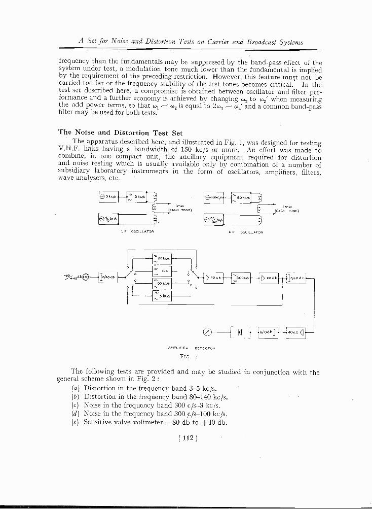
The Noise and Distortion Test. SetThe apparatus described here, and illustrated in Fig. 1, was designed for testing
V.H.F. links having a bandwidth of 150 kc/s or more. An effort was made tocombine, in one compact unit, the ancillary equipment required for distortionand noise testing which is usually available only by combination of a number ofsubsidiary laboratory instruments in the form of oscillators, amplifiers, filters,wave analysers, etc.
0 3 kcis 3kc/s*-..
IrnWF(EACH TONE)
Io/aodb
L F OSCILLATOR
aokc/s
I kc
'400 kcjs0
-cti 3 kc/s
O 80 kc/s.-f* 80 kc/s
mW(EACH TONE)
(DIDD.01,4,
aOdb
H F OSCILLATOR
300c/s aodb
0AMPLIFIER DETECTOR
FIG. 2
o/todb
. OM 0 d b
do db
The following tests are provided and may be studied in conjunction with thegeneral scheme shown in Fig. 2 :
(a) Distortion in the frequency band 3-5 kc/s.(b) Distortion in the frequency band 80-140 kc/s.(c) Noise in the frequency band 300 c/s-3 kc/s.(d) Noise in the frequency band 300 ,c/s-100 kc/s.(e) Sensitive valve voltmeter -80 db to +40 db.
( 112 )

A Set for Noise and Distortion Tests on Carrier and Broadcast Systems
Oscillators are available in pairs coupled to an output jack via a balanced hybridcoil. These sources are used when making the tests (a) and (b) itemised above andin accordance with the table below.
Frequencies Tone measured Distortion coefficientsdeduced
3 kc/s and 4 kc/s3 kc 's and 5 kc/s
80 kc/si and 100 kc/s80 kc/s and 140 kc/s
1 kc/s1 kc/s
20 kc/s20 kc/s
EvenOddEvenOdd
The amplifier is shown in Fig. 2 preceded by four wave filters. Two of these arethe means for selecting the combination tones referred to above and the others
0
10
20
T1 30
3 40
0ti 50wz
GO
70
33K 3211
COIL DATAL 320,511 2Min. 0 50 AT 6 kcisSUPPLIED IN CAN
3211
K
0 00
0000
0. 0
FIG. 3
provide 3 kc/s and 100 kc/s pass -bands for use when measuring noise. (Figs. 3 and 4.)Other positions of the selector switch permit measurements without preliminaryfiltering and are useful for measuring fundamental tones and for general purposes.
Circuit Description(1) The amplifier and filters. The input signal, which may be balanced or
unbalanced to earth, is injected at the appropriate jack (Fig. 5) and fed via a singlestep attenuator to selector switch S1. The signal reaches the grid of V5 throughone of four filters or a resistive attenuator, each path having the same attenuationat the frequency at which it is used for measurements. It will be seen that theinput impedance is 600 ohms which follows standard practice in carrier telephony,
( 113 )

A Set for Noise and Distortion Tests on Carrier and Broadcast Systems
and levels where quoted are expressed in decibels relative to 1 mW. The measure-ment of distortion must often be made in the presence of noise and the bandwidthof the filters used for distortion tests requires some consideration. The more narrow
.5
v5
COIL DATAL 10 m1.1448 TURNS OF 32 SWGWOUND ON I STG RING
IOR,H
SK
I kc/5
0
10
20
30
40
50
GO
70
10K
10 kc./5
FIG. 4
100 kcIS 1M8/5
GAIN
/840 680 7."
680
3 3N 6.81(
33k FiG 4 .----.Goo
44,341(
FIG II680
4,-AAW-3 35
t4 7680
NPFIG G
5 z
FIG 7
4735 33
GAIN 2
Na',
TEL a-.
FIG. 5
the band the more the noise that can be tolerated, but at the same time frequencyalignment of oscillators and filters becomes more critical. A reasonable compromiseusing inexpensive band-pass filters, permits measurements down to -80 db. onmost practical equipments without requiring frequency alignment closer than 1%.The practical filter characteristics and circuits are shown in Figs. 6 and 7. The
( 114 )

A Set for Noise and Distortion Tests on Carrier and Broadcast Systems
filter following V5 (shown in Fig. 8) is a 300 c/s high pass design which is requiredfor noise measurements and is conveniently placed in this position to suppress humpicked up in the rather extensive grid circuit of V5. A slight fall of response is caused
2
12
22
32
-11
.2 420-1
'1! 52
.; 62
72
1
I
47K 611 -004
LI
4 7 K
COIL OATAI, GH EP%La. 72mHE 2%Min 0 50 m I kc/SSUPPLIED 04 CAN
I
00
cisFIG. 6
by this filter in the region of 100 kc/s which is, therefore, corrected by the simpleresistance capacitance network following V6. The net gain from input to grid ofV7 is 40 db. when the first and second attenuators are in positions of zero attenuation.
00
0
10
20
_a.4
40
I- 50cc
60
30
70
0
G.85 1 ILI I if. 1 I 1.7 1 1 1 1 I6.5K
4/5 155
001 002 .coi
4,
5005
L 90mH t a Sim 0 SO AT 20 m/sT Pam I 'TM Ssc 00 411 0 30 AT 20M/s
Us
FIG. 7The following valves V7 to V10 comprise an amplifier of 40 db. net gain incorporatingtwo further attenuators 0-40 db. in 10 db. steps and 0-10 db. in steps of 1 db.A position of switch S1 passes the input signal directly to the grid of V7 (impedance
( 115 )
OO

A Set for Noise and Distortion Tests on Carrier and Broadcast Systems
600 ohms) providing an amplifier for measurements from +40 to -40 db. over afrequency band 30 c/s to 170 kc,,s (Fig. 9) and is useful as a general purpose levelmeter. Two pre-set gain controls are shown in the circuit of the amplifier, these are
i
T.
--i- -1. T
2 , OS OM 03-i-
IIID
is 2 /1
A - II -
00, DATAL. Gam! ezM.n 13 .3 AT 500 2.13
LOSS AT 50,,S 30 ak,
10
2
GO
7000
ye
FIG. 8
used to set the gains of V5 and V6, and V, to V10 respectively, and are referred tolater in connection with the alignment The type meter circuitsupplied from V10 is returned, not to earth, but to a point on the cathode load.
0
2
3
El 4
2 5
'a;3
7
(BALI
O " N 8.4 1 1 1
FIG.UB
9
This enables crystal rectifiers X1 and X2 to be used as meter overload protectorswithout introduction of a separate negative bias supply. When an input is plugged
O
0
8
0§
( 116 )

A Set for Noise and Distortion Tests on Carrier and Broadcast Systems
into the jack marked " meter ", the meter circuit is used alone and the overloadprotection is inoperative. A signal of 0.8 volts r.m.s. (1 mW when impedance is600 ohms) will deflect the meter to half scale (50 ,uA). Consideration of the amplifierand attenuator locations will show that whilst the meter is on scale, overload atany stage is impossible whatever the individual settings of the attenuators.
0018r4Ei
33K
33K
4 7K1-250V (.4
FIG. I0
K
Pmm 73K SEE 4214 CTT2_ Run 24YEN SEE 15mH CTT3 PRIM, IN SEE. 40mMT5 Pmm. - IN SEC 40mHTA. PRI. 4mN SEC 10AENTA PR RR - 4m3 SEC i0 }ENALL VALVES TYPE E F 9;
1500).41F- 3LEN oL11 es
5 4
7j-egYtoo APS7-
(2) Oscillators. The oscillator circuits, as shown in Fig. 10, are of conventionaldesign having resistive control of feedback for use as a level adjustment. For measure-ment of a beat tone depending on the product cos colt. cos (02t the purity of eachtone is of only secondary importance but it is evident that measurement of oddpower terms depending on the product cos 2w1t cos 02t demands a pure fundamentaltone of frequency co,. One oscillator in each band is therefore filtered to removeharmonics (Figs. 11 and 12). Balance hybrid coils are necessary for the outputcircuits in order that each oscillator may be injected into a common input circuitwithout causing modulation of the other. In practice this has not been founddifficult and approximate resistance balance is adequate. The equipment may bereadily checked for self -distortion by connecting oscillator outputs directly to theamplifier input and making measurements of even and odd distortion coefficientsin the usual way. Results obtained in this model were :-
L.F. -Even ... -75 db. H.F. -Even ... -82 db.-Odd ... -80 db. -Odd ... -80 db.
(3) Alignment. Alignment of the set is straightforward and when once carriedout requires only occasional checking and correction. Since the oscillators arebrought out to jacks, they may be connected directly into the meter at 600 ohmsimpedance (socket provided) and adjusted to deliver 1 mW. One of the oscillatorsmay then be used to calibrate the amplifier. Switch positions 1 and 3 respectivelyof selector S1 enable " gain 2 " and " gain 1 " to be used separately to set the gainof each section of the amplifier. If the oscillators or filters become off -tuned therequired signal may suffer some attenuation and false readings would then be
( 117 )

A Set for Noise and Distortion Tests on Carrier and Broadcast Systems
obtained. Since oscillator levels are set up after filtering, automatic correction isobtained for change in filter insertion loss and the only critical relationship isbetween the band-pass filter, preceding the amplifier, and the difference tone, which
0
10
20
30
40
50
70
330 'AN
c.3.3K .016µF .0 DuF3 3K -
COIL DATA
11- 3°8;05TUR75 OF 36 SAGWOUND ON 2 STC CORE5TYPE LP 67060
1000 10 kc/s
FIG, II
is being used as the basis of measurement. Alignment is carried out by connectinga non-linear load for distortion test in the usual way and adjusting oscillator
0
10
20
30
40
50
60
70000
3.311 12m11 12 rni1
COIL DATAL le mH 72%Min.0 CO AT IGO KC/s
3.3K
000
c/3
FIG. 12
00000
00
0Q.
trimmers for maximum response. By this method, although the absolute testfrequencies may drift slightly, the beat tone is always accurately aligned with theamplifier filter.
( 118)

THE MARCONI-FARMER INTEGRATINGX-RAY DOSEMETER.By A. W. LAY, A.M.I.E.E., F.Inst.P.
The following article describes an instrument designed to measure indirectly thedosage rate and the total dose of X-radiation administered to a patient.
HE medical use of X-rays can be divided into two main categories :-(a) Radiographic and Diagnostic, used for X-ray photography and screen
examination of biological material.(b) Therapeutic, for the treatment of disease by X -radiations.
In both these cases it is essential to be able to correlate the effect on the livingtissue with the ionisation produced by the radiation.
This information is very difficult to obtain as there is no direct way of measuringthe ionisation produced in tissue either alive or dead.
The usual method of determining the degree of ionisation in gases, by measuringthe saturation current which the ions are capable of producing, cannot be used intissues, for even if it were possible to apply an electric field across a biological materialto obtain the saturation current, this would set up simultaneously a much largercurrent independent of ionisation.
To determine ionisation in living tissue we must therefore resort to indirectmeans.
When a beam of ionising radiations impinges upon a material, ions are liberatedduring the whole period of exposure, and during this time a definite number of ionpairs will have been produced, which represents the total amount of energy transferredfrom the beam to the material. The total number of ions may be distributed througha large or small volume and the ionisation is seldom strictly uniform. The effecton the individual cells may thus be different. It is therefore important to knowthe number of ion pairs created by the radiation. Assuming that sufficient of theabove information is available it is then possible to correlate the observed biologicalchange with the amount of energy, represented by the ionisation supplied to theliving cells, and this correlation will be quantitative if means, either direct or indirect,are also available which will enable the biological changes to be measured.
The inter -action of radiation and matter depends almost entirely on the atomicnumbers of the elements, and their respective proportions in the materials, and noton their state of aggregation.
Nearly all the ionisation produced in organic material is due to oxygen, nitrogenand carbon components since the atomic number of hydrogen is 1.0, and thereforeit contributes almost negligible ionisation.
Atmospheric air consists mainly of nitrogen and oxygen and therefore givesvery close approximation to living tissue as far as its quantitative reaction to radiationis concerned. The ionisation which is produced by the radiation in air can also beeasily measured.
We may say then that the number of ions created in one gramme of living matteris nearly the same as the number of ions created in one gramme of atmospheric
( 119 )
The Marconi -Farmer Integrating X -Ray Dosemeter
air when exposed to the same conditions of radiation, and the one to one corre-spondence is almost independent of the quality of the radiation.
Ionisation measurements and their significance.In practice, the energies which are absorbed by the volume from the beam are
too small for measurement by thermal methods, so recourse is made to the fact thatwhen absorption of the beam takes place in air the latter is rendered conducting, andthe saturation current through a given volume of air becomes a measure of the rateof absorption of energy in the specified volume. It is upon this basis that theInternational Committee for Radiology Units, which met in 1937, defined the unitof X-rays and of gamma rays.
This unit is known as the roentgen. It is usually symbolised by " r ", and isdefined as the quantity of X-radiation or gamma radiation that produces, in 1 c.c.of dry air at 0° C. and 760 mm. of mercury (or 0.001293 g) ions carrying 1.0 electro-static unit of electricity.
The unit so defined corresponds to 2.082 x 10⁹ ion pairs under the conditionsspecified. Radiation quantity is thus expressed in roentgens, and the measurementof dosage rate is expressed in roentgens per minute.
When considering dosage, some specific points must, however, be emphasised.Firstly, the secondary electrons should be fully utilised in producing ions, andtherefore they must not strike the wall of the ionisation chamber-yet to be described-before their energy is completely expended ; furthermore, there should be no walleffect, which means that neither the primary X-rays nor the secondary electronsshould impinge upon any scattering material which can introduce secondary radiation.
The strict fulfilment of these conditions involves practical difficulties whendealing with a small portable instrument such as we are about to consider. Theycan, however, be met, and are essential in setting up a standard against which aportable instrument may be calibrated. Such a standard, briefly, takes the formof two large plates with an air space between them ; guard plates and other precau-tions must be taken to ensure accuracy. The spacing between the plates must bewide enough to ensure that if any photo -electrons strike them, their contribution tothe ionisation is negligibly small. For a parallel plate type of standard chamber,12 cm. spacing is satisfactory for 200 kilovolts. An electrometer device is used tomeasure the current through the condenser plates as a result of the ionisation of theair dielectric under the influence of the X-ray beam.
A full description and theory of absolute standard chambers is beyond the scopeof this article, but the basic considerations may be summarised thus :-
Since the degree of ionisation is determined by the mass absorption coefficientof X-radiation by the gas, corrections must be made for the temperature and pressureof the air in the chamber. Under these circumstances, if I represents the currentmeasured by the electrometer in electrostatic units, L the effective length of thecollecting electrode, A the area of the limiting diaphragm in sq. cms., T the absolutetemperature, and p the pressure in millimetres of mercury, then the intensity of theX-ray beam under measurement is, in roentgens per second :-
r I T 760sec L x A 273 p
By the use of an absolute standard, the number of roentgens per unit time atany specified place in air can be determined, but such an instrument is not suitable
( 120 )

1
The Marconi -Farmer Integrating X -Ray Dosemeter
for general calibrating purposes as it cannot easily be made in portable form, and itwould demand more precautions than can generally be made in a hospital X-raydepartment.
However, small and convenient ionisation chambers can be easily calibratedagainst an absolute standard and these can be used as secondary standards for usein hospitals and clinics for measuring the plant rate (or X-ray output) of X-rayinstallations.
When, however, comparison is made by using the absolute standard and thesmall enclosed thimble type of chamber (later to be fully described) to measure theintensity of an X-ray beam at the same point under the same conditions, the measuredvalues as indicated by the two types of instrument will not be the same even if bothare of the same material. This is because the wall of the small thimble chamberabsorbs some of the primary radiation, it sets up its own secondary radiation, anddoes not allow space for the complete utilisation of the secondaries. The relationbetween the readings of the two types of chambers may therefore be expected to bedifferent for every quality of primary radiation. This is especially so when thesecondary chambers are made of metal, and other materials of high atomic number,and these are of little use for calibrating purposes.
If, however, the thimble chamber is made of an organic material of approxi-mately unit density, with an effective atomic number as nearly as practicable thesame as air,* and properly designed and compensated, the ratio of its readings tothat of the standard can be made very nearly constant over the range of quality(80 kilovolts to 250 kilovolts) in which we are at present interested. Thimblechambers so compensated are said to be " air wall," and they are satisfactory for useas secondary standards.
For X -radiations above 250 kilovolts, other factors must be given consideration.Similarly, for radiations of less than 45 kilovolts the effect of photo -electrons fromthe walls of the chamber introduces another factor.
The inner walls of small ionisation thimble type chambers are coated withcarbon, or carbon preparations, such as " Aquadag," or colloidal graphite, to renderthem electrically conducting without introducing elements of atomic number greaterthan those of which the walls of the chamber are made. The atomic number ofcarbon is less than the effective atomic number of air. This means less ionisationthan if all the secondary radiations were from air. With proper precautions,however, measurements can be made with thimble type of ionisation chamberswithin accuracies of 1.0 or 2.0 per cent.
* If the wall of an ionisation chamber is made of the same atomic number as air, that is 7.3,the ionisation of the volume of air in the chamber should, theoretically, be the same as the freeair in a large standard chamber.
Also, if a chamber wall material has the same effective number, Neff, as air, it will, over arange of wavelengths from 0.1 to 1.5 A have the same effect on the ionising current as air.
The effective atomic number Neff can be calculated from the relation :-
Neff ==.34/a1Ni a-zNaiN1 ± a2N2
In this equation a is the fractional part of the material or atomic number N. By a suitablechoice of N and a, the effective atomic number of the materials composing the chamber can beadjusted to 7.3.
( 121 )

The Marconi -Farmer Integrating X -Ray Dosemeter
The functional details of the Instrument.An idea of the general scheme of the design of the Marconi -Farmer Integrating
Dosemeter can be obtained from Fig. I. Photographs of the instrument with coveron and off are shown in Figs. 2 and 3. Let us consider first the ionisation chamber,which, with the directly associated electrometer valve V1, may be considered as theheart of the instrument.
NTEGRATINGUNIT
PSA
ILECTRCNICUNIT
IONISATIONCHAMBER
RS5
IC I
I Pa
COPPERBRAID
SCREENING
ARMOURED
VI
APS5
A
T"
LI
Ca Cl
r;
-I -
VS
2-3 B
T_T
lay IA
0
TC2
RIO
RS
21
O
O
Rs, -0
-IH
O
0
P52
4;
FIG. I
ARMOURECTUBING
In the design of this ionisation chamber the atomic number of the materialchosen for the chamber must be as near as possible to that of air, or 7-3. Someorganic compositions, such as certain grades of Bakelite, Tufnol and Nylon, meetthis requirement to a fairly close approximation, and give the necessary mechanicalstrength and rigidity.
It will be seen from the diagram that the ionisation chamber actually constitutesa small cylindrical condenser of which the centre electrode is a small aluminium wirechosen because of its low atomic number and ease of manufacture. A suitablematerial for this would be the same as for the chamber wall, but a Bakelite or Tufnolwire of 0.20 inches diameter would be too expensive to manufacture in quantities.A few have been made, however, under laboratory conditions.
However, the organic materials already mentioned can be taken as beingsuitable for the requirements of this instrument, and within practical limits theionisation chamber may be considered as being " air walled," which renders itsuitable for measurements in the range of X-radiation covered by the specificationof the dosemeter as a whole. It should be emphasised, however, that for measure-ments outside the range specified, calibration against N.P.L. standards should be
( 122 )

The Marconi -Farmer Integrating X -Ray Dosemeter
made and correction supplied. For X-radiation above 500 kilovolts peak, thechamber would have to be designed with thicker walls.
Before proceeding to describe the general functioning of the circuits, it may beas well to recapitulate the factors which influence the current of the electrometervalve. When the grid is biassed negatively the grid current is influenced by :-
(1) Electrons passing from cathode to the grid.(2) Positive ions which are produced in the residual gas.(3) Positive ions produced on the anode due to electron bombardment.(4) Positive ions from the anode.(5) Poor insulation between the grid and other electrodes.(6) Primary electron emission from the grid.(7) Positive ions from the cathode.(8) Photo -electric emission from the grid.(9) Secondary emission from the grid due to positive ion bombardment.
(10) The relatively high velocity secondary electrons from the cathode due topositive ion bombardment.
FIG. 2 FIG. 3
In the prototype model of the instrument the nominal mean anode voltage onthe electrometer is 4.6 approximately ; this swings about 11 volts when theionisation chamber is active under the influence of the charging condenser and
( 123 )

The Marconi -Farmer Integrating X -Ray Dosemeter
X-ray beam in turn. This low anode voltage is less than the ionisation potentialof the residual gas in the valve and therefore positive ionisation within the valvewill be eliminated. For the same reason there will be practically no ionisationproduced on the anode surface due to electron bombardment.
Furthermore, since the emission of ions from the anode is a function of tem-perature, this will be reduced ; from this it follows that the physical phenomenaenumerated by (9) and (10) will also be reduced to values which are practicallynegligible.
The insulation resistance of the grid circuit of the electrometer valve is of theorder of 1017 ohms to avoid leakage, but to maintain this the valve must be keptchemically clean and dry. It is also essential to reduce as far as possible the photo-electric emission from the grid. To accomplish this, the valve should be operatedin the dark, or in low ambient light intensity.
Under suitable operating conditions the grid current can be kept as low as 10-14to 10-15 amps. In the prototype model the grid system, comprising the grid of thevalve and the central electrode of the ionisation chamber, was biassed to 6.3 voltsnegative with respect to the electrometer valve cathode, which is 140 volts positivewith respect to earth. This gives the active central electrode of the chamber apositive potential of 133.7 volts to earth.
When the X-rays pass through the ionisation chamber at the end of the cable,a current of the order of 10-12 amps. is produced across the chamber and this currentflowing into the cable capacity causes a gradual change of potential on the grid ofvalve V1, which in its normal working cycle has no other connection to the highinsulation electrode.
This valve (E.T.1) is of low impedance, and to keep the grid current small,must be worked at the low anode voltage mentioned later.
V1 is in series with the high anode resistance, R5, which effectively forms aconstant current circuit, and during exposure of the ionisation chamber to X-rays,the anode potential rises by an amount which is approximately equal to the fall ofgrid potential.
The changing anode voltage is applied through the winding of the transformerT2 to the grid of the oscillator valve V2, the cathode of which is held at a potential ofabout 8 volts above the cathode of V1 by the resistances R4 and R11, and duringmost of the cycle its anode current is completely cut off.
As the grid potential rises, a point is reached at which this valve starts passingcurrent and when this reaches a fraction of a micro -ampere the valve breaks intooscillation causing a sudden increase in current to about 2.0 mA and this closes therelay Z2.
When the relay is energised it actuates three contacts as follows :-(1) It switches the high insulation terminal of the charging condenser C12
from the H.T. point of the stabilovolt momentarily to the grid of theelectrometer valve ; thus applying a small positive charge to the grid.
As the H.T. voltage is high compared with the grid swing, thischarge is practically independent of the grid potential at the instant,and the bias given to the chamber is therefore independent of the valvecharacteristics.
( 124 )

The Marconi -Farmer Integrating X -Ray Dosemeter
(2) It quenches the oscillator by short circuiting the primary winding ofthe transformer T2.
(3) It switches an impulse to the dial circuit which advances the blackpointer on the instrument by 5 roentgens on the scale. When thecharge is applied to the grid of V1 it drives the grid of the oscillatorbelow the cut off point again, and the circuit is thus rendered quiescentuntil the next trip.
Since the grid of V1 is floating it is essential that it must be activated at anappropriate fixed potential when the instrument is switched on. To accomplishthis the relay Z1 is operated by turning the Dosage Switch in the dial unit whichdisconnects the grid from its pre-set tapping point on R10.
The stabilovolt maintains a P.D. of 140 volts between the cathode of theelectrometer valve and earth. This ensures the necessary saturation conditions inthe ionisation chamber. It also provides a constant charging voltage of 140.
The valve V3 is an indicator which shows the instantaneous potential of V1 andtherefore the point in the cycle which the discharge has reached. It is a cathodefollower system in which the anode current passes through the meter M1 on the dialunit, in opposition to a fixed backing current, therefore the fall in the meter readingcorresponds to a fall in potential of the chamber electrode.
This is useful in radiological practice, and it also facilitates fault location.When the mains are switched on, the H.T. working voltage is established and .
the meter should read full scale deflection.As the valves warm up, opposition current will flow through V3 and the meter
should settle down to about mid -scale, in which position it should remain untilrelay Z1 is operated and X-rays pass across the chamber.
The meter indication should then fall steadily over about 10 divisions until theoscillator bursts into activity when it will return to the upper limit of its cycle andproceed to repeat as long as the X-ray tube radiates.
When radiation stops, the pointer should dwell at whatever position in the rangeit may be at that instant.
Assuming that the radiographer has set for the prescribed dose, with the patientin position, he now switches on the mains (S1) and energises the transfolluer ; thecathodes of the valves are then heated to their working temperature. The mainsshould be left switched on during the daily working sessions.
At the end of a period of not less than 10 seconds, the H.T. switch S2 shouldbe thrown on. This closes all the valve anode circuits and the energising circuitsof relays Z1 and Z2.
The relay Z1 acts to switch over and energise, through the associated rectifier,the pulsating coils of the integrating mechanism, symbolised in simple form as Z4.The grid and screen of the electrometer valve, and active central electrode of thechamber, have been biassed to the 6.3 volts negative with respect to the cathode,as shown in Fig. 4. The grid system of the electrometer valve is thus left isolatedat that working bias. It is important that this bias is maintained until the X-raybeam is switched on to the chamber. There may be some delay by the radiographerin doing this, hence the paramount importance of high insulation of the electrometergrid system and of the chamber being maintained.
The meter M.1, which has the engraving " Charge Indicator " on its dial, is forthe purpose of indicating the charge condition of the ionisation chamber. This meter
( 125 )

The Marconi -Farmer Integrating X -Ray Dosemeter
is also a leakage indicator. Its pointer should show no discernible movement whenthe dosemeter as a whole has settled down after switching on, and when no X-raysare being applied to the chamber.
IONISATIONCHAMBER
PATIENTSBODY
VI65 VOLTS
_ -CABLE
SCREEN
140 VOLTS +
133 7 VOLTS +APPROX -
FIG. 4
HT +5)140 VOLTS
R5
4 VOLTS APPROX
GRID OFOSCILLATOR
Z2
VE
HT +140 VOLTS
CHARGINGCONDENSER
ELECTROMETER SCREENOPERATING POTENTIAL SETWHEN CALIBRATING
potential difference of 120 voltsupwards is necessary to ensureionic saturation of the airmedium, which is essential foraccuracy.
With the chamber andgrid operating conditions soset, let it be supposed that theX-ray plant is switched on andthe beam impinges on thechamber (see Fig. 5). Underthe influence of the beam theair in the chamber is ionised,and positive ions travel fromthe central electrode to earth,and negative ions to that elec-trode, with the result that there
X-RAYS
( 126 )
Associated with the dis-charge meter is the valve V3,and this system virtually con-stitutes a valve voltmeter forgiving an indication of therelative potential of the ion-isation chamber over the 5.0roentgen increments of X-radi-ation.
The central electrode of thechamber and the surroundingconducting wall thus consti-tutes a cylindrical condenser,with an air insulating medium,across which there is a poten-tial of 133.7 volts approxi-mately. This is the conditionof the chamber when theX-radiation is first applied. A
140 VOLTS+
)
HT +140 VOLTS
R5
OSCILLATOR GRIDSWINGS MORE NEGATIVE
+ CHARGE ToTHE CHAMBER
V2
Z2
HT +140 VOLTS
(280 VOLTSTO EARTH)
THE CONDENSER ISCALIBRATED TO DELIVERA CHARGE CORRESPONDING
TO 5.0 ROENTGENS
FIG. 5

The Marconi -Farmer Integrating X -Ray Dosemeter
is a leakage current across the chamber and the potential difference acrossit falls.
An important feature of the design is that the ionisation chamber may takethe form of a head which may be used at a remote distance from the main electronicunit containing the electrometer valve. The connecting link between the chamberand the valve is a highly insulated and screened Telcothene cable. This has acapacity between the core and screen of 21.5 picofarads per foot. The total capacitydue to this cable link is in parallel with the natural capacities of the chamberand the electrometer grid system.
It will be appreciated therefore that the length of the cable link is limitedbetween the two extremes of being too short and too long, these being 8.0 and16.0 feet respectively.
In the prototype model the length of the cable link was 11.5 feet, and itsmeasured capacity was 260 picofarads. The capacity of the chamber and its bodywas 12.0 picofarads, and that of the electrometer grid system was 9.3 picofarads.This gives a total capacity of this system of approximately 282 picofarads.
Now from the definition of the roentgen
we have r (in roentgens) =CV CVv-v
where C and V are in electrostatic units and v, the volume of the chamber, is incubic centimetres.
After the dosemeter as a whole had been set and checked at a Hospital wherea Victor X-ray installation was used, and using a Victoreen sub -standard dosemeteras a standard of reference, it was observed that, when a quantity of X-radiation of5.0 roentgens had been applied to the chamber the potential of its central electrodeand the electrometer grid had fallen to 130.5 volts positive with respect to earth,the volume of the chamber being 0.555 ccs.
Convert"ng voltages and capacities to E.S.U.'s and substituting these experi-mentally measured values in the above equation, we have
3.2 2-82 x 9 x 10r - X - 4.89 roentgens.300 0.555
The slight difference between this and the empirical calibration is attributed todifficulty in measuring the total capacity of the system to a high degree of accuracy.
We have so far considered only the initial increment of 5.0 roentgens acting onthe chamber. The effect of this was to lower the grid potential by 3.2 volts. Fromthe characteristic curves for the valve, it will be seen that the effect of this is toreduce the current practically to zero and thus to cause a positive rise of potential onits anode. It is obvious that this positive pulse is passed on to the grid of theoscillator valve V2, whose anode circuit is closed. This valve has a steep anodecurrent/grid voltage curve and it is set by means of the bias control R11 at a criticalpoint which causes a rapid rise of current through the relay Z2. This relay thenacts to switch over the three contactors with which it is loaded.
It should be mentioned here that when the positive pulse is passed from theelectrometer anode to the grid of the oscillator valve, V2, the transient nature of theimpulse in the circuits around the latter render the condenser C9 necessary to ensureproper functioning of the oscillator.
( 127 )

The Marconi -Farmer Integrating X -Ray Dosemeter
Referring now to the charging condenser C12, which is also a calibrating device,it will be seen that before the relay Z, is switched from its initial position this chargingcondenser is across 140 volts and accordingly charges up to that potential. When,however, the relay Z2 acts to switch over, this condenser is switched from thecommon H.T. to the ionisation chamber, and also to the electrometer grid-whichis now isolated to relay Z, from its initial bias supply down R10.
It will be understood that as the condenser C12 is switched by relay Z2 to thechamber, it shares its charge with the total capacity of the chamber-electrometervalve system. The effect of C12 sharing its charge is to restore the bias of the gridsystem to 6.3 volts negative to the cathode from the 9.5 negative to which it hasfallen due to the discharge current across the chamber under the influence of theionising X-radiation. Now that the negative bias on the electrometer valve hasbeen reduced to 6.3 volts negative, it takes current and its anode potential drops ;so also does that of the oscillator valve grid, and the current through this lattervalve falls to the critical value for which it was originally set (Fig. 6).
The cycle of events nowrepeats itself whilst the cham-ber is subject to X-rays
It will be obvious thatwhen Z2 is energised andswitches over, its middle con-tact short circuits the grid ofthe oscillator and thus rapidlydamps dpwn any spuriousoscillation in this system. Itsthird contact closes the 12.0volt circuits in the IntegratingUnit which is housed in thecabinet.
This cabinet contains themains switch, S1, fuses FZ1-2,H.T. swii ch S2, charge indicatorM.1, integrating mechanism Z4,and its associated rectifier Reel,indicating buzzer buz1, andrelay Z3 in electrical associationwith Z4.
X-RAYS
IONS
ELECTRONS
NEUTRReturning to the relay Z2, PARTICLEAL
S
this has been caused to act dueto the sequence of events fol-lowing the application of theX-ray beam to the chamber.
1..2. VOLTS
APPROXSWING
-ter9.5 VOLTSAPPROX
140 VOLTS +
HT +YI40 VOLTS
R5
OSCILLATOR GRIDSWINGS MORE POSITIVE
130.5 VOLTS
FIG 6
va
Z2
HT +140 VOLTS
(280 VOLTSTO EARTH)
CHARGINGCONDENSER
It will be remembered that relay Z1 has closed to the left, looking at the diagram, andwill remain so until the mains switch is broken at the end of a working session. Accord-ingly the circuit to the " signal " coils via the rectifier recl is closed at that point,but until relay Z2 switches to the left the signal circuit is broken here.
Therefore as Z2 is closed, due indirectly to the influence of the X-ray beam,a pulse of current passes through the signal coils of Z4, which represents in simple
( 128 )

The Marconi -Farmer Integrating X -Ray Dosemeter
form an electro-mechanical integrating system. This is an application and improve-ment of a well-known impulse system used in horology. It consists of a springloaded toothed wheel which a pawl engages to rotate against a spring.
The pawl is activated by an armature pulled magnetically towards the core ofthe coils of Z, when the pulsating current circuit is switched by Z, in the manneralready explained. By means of a control on the panel of the integrating unit, thedose is set by the hands shown at Z. One is black and is set at zero on a dialcalibrated from 0 to 550 roentgens. The other, coloured red, is set around the dialat a figure corresponding to the dose which has been prescribed for the treatment.A friction clutch device protects the setting mechanism from being strained anddamaged by forcing past legitimate rotation.
In order to facilitate accurate zero setting by the hands, the contacts which theycarry in rotation are cushioned by springs to give flexibility in positioning the handsaround zero and take up any slight loose spacing due to the gear teeth and manufac-turing discrepancies in the integrating mechanism as a whole.
The diagram shows that the buzzer (buzi) and relay Z, are effectively in serieswith the two contacts carried by the hands, as indicated by Z4. When these contactsare caused to meet by the rotation of the hands, they meet and close their contacts,and thus energise the buzzer and the relay Z3. The buzzer thus gives an acousticwarning that the prescribed dose has been delivered.
It will be seen from the diagram that relay Z3 is loaded with contacts connectedby a pair of leads to the output sockets P3. The purpose of this relay is to operateany electro-mechanical device which may be fitted on the X-ray installation to cutoff the beam at the end of the specified dose and thus ensure that the patient doesnot receive an overdose.
Perhaps it should be mentioned that V4 is a stabiliser for the II.T. supplysystem ; the other part of this needs no explanation.
At this point it should be repeated that the highest possible insulation-withdue regard to the radiological requirements of compactness and convenience ofapplication in body cavities-must be maintained. The insulation between thecentral electrode of the chamber and that of its conducting inner wall must be of thesame order as the associated grid of the electrometer valve, that is l0" ohmsapproximately. Similarly, the wiring around that valve must be of the same order.
This high insulation must be preserved throughout manufacture, which meansthat great care must be taken at each stage of assembly and wiring to guard insulatingsurfaces against contamination by conducting material. For example, the handlingof the perspex insulating blocks on the relay by naturally clamp hands has been thecause of much trouble in research work on the first model. Another cause ofextraneous effects has been that of light falling on the grid of the electrometer valvewhen it is exposed. For this reason the cover should be in position on the electro-meter unit when the instrument is working.
In order to protect the grid of the electrometer valve and its directly associatedcomponents, such as relays Z1, Z2, the charging condenser Cis, and the input from thecable connector between the valve grid and the ionisation chamber are all containedin a lead box with a good fitting lead cover.
Silica gel air driers are provided to maintain a dry atmosphere in the cabinets.This, and the maintenance of chemical cleanliness throughout the instrument, andin - particular of the ionisation chamber and all material around the electrometervalve is of paramount importance.
( 129 )

MARCONI NEWS AND NOTES
INTERNATIONAL STUDY GROUP VISITS MARCONI'S
AFTER travelling through France, Holland, the U.S. \. and England, studyingall the aspects of television in those countries, the Television Study Group ofthe International Radio Consultative Committee ended their extensive tour
with a visit to the birthplace of the Radio Industry on Thursday, May 4th, 1950,when the delegates were the guests of Marconi's Wireless Telegraph Co., Ltd.
The delegates had an earlydemonstration of Marconiefficiency when they left Lon-don in three coaches. Theleading coach had been speci-ally fitted with V.H.F. radioand contact was made withChelmsford when the coacheswere at Stratford. Continuoustwo-way working was main-tained, and the arrival of thecoaches at Chelmsford wastimed exactly.
In the large club -room ofthe Marconi Athletic and SocialClub, Mr. F. N. Sutherland,Mr. F. S. Mockford, and otherhosts met the C.C.I.R. partyand tea was served.
After a tour of the NewStreet Works the delegateswent to Ingatestone for dinner, where they were met by Mr. H. G. Nelson, who lateraddressed the delegates in both English and French.
Mr. F. N. Sutherland and Mr. F. S. Mockford talkingof the delegates.
to some
Television Garden PartyThe delegates then travelled to Baddow where a " Television Garden Party "
had been arranged. This Baddow show was brilliantly conceived and organised,not only was television, in all its aspects, fully displayed and explained but theseriousness of the evening's work was pleasantly tempered by a live televisionprogramme and excellent catering.
Of great importance to the delegates were the " side-shows " of the GardenParty. These included a lecture on " Evaluation of Picture Quality " and a com-parison of 16 mm. cine film with 16 mm. television film recorded from 405 lines.Other " side-shows " which drew large audiences were the " Investigation of ScanningStandards, Monochrome and Colour," and the " Spot Wobble " demonstration.
A spectacular " live " event opened the Garden Party. On their arrival thedelegates were shown into a large marquee erected on the lawn. In the marquee
( 130 )

Marconi News and Notes
Mr. E. B. Esping (Chairman of Study Group ii) and Mr. F. D.Heegard inspect a transmitter valve.
Mr.
were 15 -inch television moni-tors, and on the roof of theresearch laboratories was aMarconi Image Orthiconcamera. The first demonstra-tion of Marconi television seenby the delegates was a brilliantpicture of the Dagenham GirlPipers as they marched throughthe main gates and up thedrive, counter -marchingthrough the marquee they pro-vided the touch of colour andlively music which was thekeynote of the evening's enter-tainments.
A continuous televisionprogramme was provided fromthe Baddow television studioand relayed to receivers situ-
ated at many points throughout the building and in the marquee. This programmeincluded musical items, a table -tennis display by members of the M.A.S.C., and aninteresting " interview " on the history of wireless, illustrated with some of theunique historical exhibits whichthe Marconi Company havepreserved. This item was givenby Mr. W. T. Ditcham, whowas interviewed by Mr. BarrieEdgar of the B.B.C. AnotherB.B.C. star, Miss Sylvia Peters,did the announcing, and laterinterviewed delegates beforethe cameras.
The whole programme wasproduced and directed by Mr.Stephen McCormack,the B.B.C.television producer.
The final item by theDagenham Girl Pipers demon-strated the remarkable pro-perties of the Marconi ImageOrthicon cameras. Despite thefact that only a modicum oflighting was in use for the benefit of people moving between the laboratories and themarquee, the roof camera provided excellent pictures of the girls even while theymarched along the lane in almost total darkness.
The Marconi " Television Garden Party " was a demonstration of television atits best, and will undoubtedly have done much to enhance the prestige of Britishtelevision all over the world.
H. G. Nelson and Mr. F. N. SutherlandDagenham Girl Pipers.
( 131 )
with the

Marconi News and Notes
The
WILLIAM GEORGE RICHARDS
1T is with deep regret that thedeath is announced of Willis .mGeorge Richards, Pi blicity Man-
ager of Marconi's Wirele Tele-graph Co., Ltd., at his h( me inChelmsford, on June 15th, at theage of sixty-one. His death },ringsto a close a long and active careerin journalism and publicity.
Born in Cheltenham on March6th, 1889, Mr. Richards began hisjournalistic career on being appren-ticed to the Stroud Journal. In1909 he joined the reporting staffof the Citizen (Gloucester), where heremained for the next five years.
As a member of the TerritorialArmy he was called to the coloursat the outbreak of war in 1914, andwent overseas with the GloucesterHussars (Yeomanry). He sawservice in the Middle East (CanalZone) and Mesopotamia, and wasMentioned in Despatches.
After demobilisation Mr.Richards returned to journalism as a reporter on the Yorkshire Evening Post and, during thenext two years, became keenly interested in the then young science of wireless and, despitemuch criticism from his associates, foretold a great future for Marconi's invention. His faith init was so strong that, on December 1st, 1920, he joined the Marconi Company as an assistant inthe Publicity Department under Mr. Arthur Burrows (later to become famous as " Uncle Arthur "of the B.B.C.). On January 1st, 1923, he succeeded Mr. Burrows as Chief of the PublicityDepartment.
Up to the death of the Marchese Marconi, in 1937, Mr. Richards was his close and intimatefriend, and he was probably the world's greatest authority on Marconi, the man and scientist.Mr. Richards was appointed Managing Director of Radio Intelligence, Ltd., where he wasstill responsible for initiating and controlling the publicity for all the Marconi Companies, on
January 1st, 1932. When this Company was dissolved, he again took up the position of PublicityManager of Marconi's Wireless Telegraph Co., Ltd. He also directed publicity for The MarconiInternational Marine Communication Co., Ltd.
For his work in advertising he was elected a Member of the Incorporated Society of Adver-tising Consultants.The possessor of a keen mind which could strike straight to the heart of a problem, W.G.
Richards's greatest asset was his ability to act as a guide, mentor, and personal friend, to allwho w--rked for him : several former members of his staff have founded successful careers inpublicity on his teaching.His passing will be mourned all over the world, for his work was admired by all who knewhim, and his friends were legion.He leaves a widow and two daughters.
CHIEF ENGINEER OF MARCONI'S WIRELESS TELEGRAPHCO., LTD., AWAR ED C.B.E. IN BIRTH AY HONOURS
G. 1\1. WRIGHT, B. Eng., M.I.E.E., Engineer -in -Chief of Marconi's Wireless TelegraphCo., Ltd., has been made a C.B.E. in the Birthday Honours.Mr. Wright originally joined the Marconi Company in 1912, and his work as a Research
Engineer and Consultant, principally done in the Company's Chelmsford establishments, gainedfor him an international reputation.At the outbreak of war he joined the Admiralty, becoming Assistant Director of ScientificResearch and Chief Scientist at the Admiralty Signal Establishment. He returned to Marconi'sas Engineer -in -Chief in 1946, and in November, 1948, was appointed a Member of the RadioResearch Board of the Department of Scientific and Industrial Research.
late Mr. W. G. Richards, Publicity Manager, Marconi'sWireless Telegraph Co. Ltd.
(132)

Marconi News and Notes
V.H.F. LINKS THE FAROESLMOST every issue of the Marconi Review brings news of yet more uses and
applications which have been discovered for Marconi V.H.F. equipment. Theubiquitous " Walkie-Talkie " has become almost as commonplace as the
landline telephone, but the latest Marconi application illustrates how the twomediums-V.H.F. radio and telephones-can be successfully and economicallywedded.
Some of the Faroe Islands have long been equipped with landline telephonesystems, including some of the earliest ex-amples of telephone instruments and all ofthem are of the manual type.
Marconi Type H.16A V.H.F. transmitter -receivers now link the telephone systems ofthe islands of Torshavn, Suderoy, andSandoy, and, for the first time, there is auniversal inter -island telephone service forall telephone subscribers.
The V.H.F.-telephone link betweenTorshavn and Suderoy covers a range of32 miles and the Marconi set is installed onthe top of a mountain on each island.Petrol -driven generators supply the powerfor these two installations.
At Sandoy-which is 10 miles fromTorshavn-the Marconi equipment is in-stalled in the telephone exchange.
Climatic conditions in the Faroes areextremely severe. Telephone wires on theislands are made of steel, instead of the usualcopper, to withstand the Arctic conditionswhich prevail over long periods. Such con-ditions are a severe test of equipment,but Marconi equipment is specially designedto operate successfully under all varieties ofclimate. ,
Situated on the top of a mountain on Tor-shavn in the Faroe Isles a Marconi TypeH.16 V.H.F. transmitter -receiver and Yagiaerial array links the telephone system ofthe island with those of Suderoy and Sandoy
isles.
SUCCESS OF MARCONI AIR-COOLEDBROADCASTING TRANSMITTERS
MUCH attention has been given in the world Press recently to the capture, bythe Marconi Company, of an order of two 100 kW. air-cooled broadcastingtransmitters for the Argentine.
This is the latest order for this model transmitter and there are, at present,orders placed for a dozen of them from Finland, Denmark, Egypt, India, andthe British Broadcasting Corporation.
It is the intention of the Argentine Government to work their two transmittersin parallel (the Marconi Company are arranging the installation for this purpose)
( 133 )

Marconi News and Notes
A typical Marconi Joe kW broadcasting transmitter. Similartransmitters are to he supplied to the Argentine Government.
to give an output of 200 kW.This will mean that the station,to be sited at Gral Pachecosome 15 miles North of BuenosAires, will be the most powerfulin South America.
Once again the uniqueMarconi High Constancy Crys-tal Drive has been chosen forthese transmitters to ensure avery high degree of wavelengthaccuracy.
The day-to-day frequencystability of a Marconi HighConstancy Crystal Drive is onecycle in 100 million (1 in 108).
Prior to placing this orderthe Argentine Government hadordered from the Marconi Corn-
pany two 20 kW. transmitters, for local broadcasting, one to be installed at GralPacheco and the other at Santa Rosa.
TELEVISION DEMONSTRATIONS IN SOUTH AFRICALABORATE arrangements were made to show television to the people ofSouth Africa when a demonstration team, engineers and equipment werespecially flown from England to Johannesburg to present what must have been
the most comprehensive television working display that has ever been taken fromone country to another.
This television show was one of the most outstanding attractions of the Wit-watersrand Easter Show which ran from April 1st to 10th inclusive.
The two British firms who made this project possible were Marconi's WirelessTelegraph Co., Ltd., and Cinema Television, Ltd. who co-operated so successfullyat the Milan Television Congress and Exhibition last autumn.
South Africans visiting the Rand Show saw a Marconi mobile television unitworking " in the field." It televised scenes in the riding arenas and various otherparts of the show grounds, and transmitted pictures, either over cables or by the newMarconi 30 -watt portable television " suitcase " transmitter, to a special TelevisionHall.
This Television Hall was divided into two sections. Visitors entered the firstportion where they were able to walk around a glass -lined studio and watch indoortheatre programmes being televised. Simultaneously, above their heads, they sawthe same programme reproduced on a row of domestic television receivers.
From this first half of the hall the people then passed into the next section whichwas a cinema especially designed to demonstrate large -screen television. Here theysaw on the cinema screen the televised programme from the studio next door.
The idea of this television show was conceived by Mr. John Schlesinger, chairmanof African Theatres.
A York aircraft was specially chartered to fly the Marconi and Cinema Televisiontechnicians and equipment to Johannesburg and back.
( 134 )

MARCONI'S WIRELESS TELEGRAPH COMPANY, LIMITED
Head OfficeMarconi House,Chelmsford,Essex.
Telephone : Chelmsford 3221.Telegrams : Expanse, Chelmsford.
ARGENTINA.Establecimientos Argentinos Marconi, Avenida Cordoba
645, Buenos Aires.AUSTRALIA.
Amalgamated Wireless (Australasia) Ltd., 47, YorkStreet, Sydney, N.S.W.
AUSTRIA.Kapsch & Sohne, Wagenseilgasse 1, Vienna XII.
BELGIUM AND BELGIAN COLONIES.Societe Belge Radio-Electrique S.A., 66, Chaussee de
Ruysbroeck, Forest -Bruxelles.BOLIVIA.
Macdonald & Co. (Bolivia) S.A. P.O. Box 879, La Paz.BRAZIL.
Companhia Marconi Brasileira, Caixa Postal No. 126,Rio de Janeiro.
BRITISH EAST AFRICA.(Kenya, Uganda, Tanganyika, Zanzibar.) Kinleven
Ltd., P.O. Box 35, Nairobi, Kenya.BURMA.
William Jacks & Co., Ltd., 517, Merchant Street,Rangoon.
CANADA.Canadian Marconi Co., Marconi Building, 211, St.
Sacrament Street, Montreal.CENTRAL AMERICA.
(Guatemala, San Salvador, Honduras, Costa Rica,Panama.) Keilhauer, Pagram & Co. Ltd., 20,Calle Oriente, No. 22, Guatemala.
CHILE.Gibbs & Co., Casilla 67 D, Santiago.
CHINA.Marconi (China) Ltd., Queens Building, Chater Road,
Hong Kong.DENMARK.
Sophus Berendsen Ltd., Post Box 372, Copenhagen V.d.ECUADOR.
Compania Pan Americana de Comercio S.A., Pichincha111-113, Guayaquil.
EGYPT.Associated British Manufacturers (Egypt) Ltd.,
Building B, 11, Sharia Emad el Din, Cairo.FAROE ISLANDS.
S. H. Jakobsen Radiohandil, Postbox 35, Torshavn.FINLAND.
de Jersey & Co. (Finland) Ltd., Mikonkatu 9, Helsinki.FRANCE AND FRENCH COLONIES.
Compagnie Generale de Telegraphie sans Fil, 79,Boulevard Haussmann, Paris, 8e.
GREECE.P. C. Lycourezos, Kanari Street 5, Athens.
IRAQ.C. A. Bekhor Ltd., P.O. Box 138, Baghdad.
ISRAEL.Middle East Mercantile Corpn., Ltd., 5, Levontin St.,
Tel -Aviv.ITALY.
Marconi Societa Industriale, Via Hermada 2, Genoa-Sestri.
LEBANON.Mitchell, Cotts & Co. (Middle East) Ltd., P.O. Box 251,
Beyrouth.
Registered OfficeElectra House,Victoria Embankment,London W.C.2.
Telephone : Temple Bar 4321.Telegrams : Expanse, Estrand, London.
MALAYA ; SINGAPORE ; SARAWAK,& BR. NORTH BORNEO.
United Engineers Ltd., P.O. Box 41, Singapore.MEXICO.
Representaciones Britanicas S.A., Avenida Madero 55,Mexico City.
NEW ZEALAND.Amalgamated Wireless (Austra.lasia) Ltd., P.O. Box
830, Wellington.NORWAY.
Norsk Marconikompani, 35, Munkedamsveien, Oslo.NYASALAND.
Lake Nyasa Development & Trading Co. Ltd., P.O.Box 112, Blantyre.
PARAGUAY.Agroindustrial y Comercial Espinoza Lda., S.A.,
Casilla de Correos No. 651, Asuncion.PERSIA.
Pasal Trading Company, Avenue Saadi, Teheran.PERU.
Milne & Co., S.A., Lima.POLAND.
J. Plebanski, Frascati 2 m 15, Warsaw.PORTUGAL AND PORTUGUESE COLONIES.
E. Pinto Basto & Ca Lda., 1, Avenida 24 de Julho,Lisbon.
RUMANIA.Saroidar S.A.R., 15 Str. Muzuel Zambaccian, Parcul
Mornand, Bucuresti, III.SAUDI ARABIA.
Mitchell, Cotts & Co. (Sharqieh) Ltd., P.O. Box 31,Jedda.
SIAM.The Borneo Co. Ltd., Bangkok.
SOUTH AFRICA (INCLUDING N. AND S.RHODESIA).
Marconi (South Africa) Ltd., 321-4 Union CorporationBldg., Marshall Street, Johannesburg.
SPAIN AND SPANISH COLONIES.Marconi Espanola S.A Apartado de Correos No. 509,
Madrid.SWEDEN.
Svenska Radioaktiebolaget, Alstromergatan 12, Stock-holm.
SWITZERLAND.Hasler S.A., Belpstrasse, Berne.
SYRIA.Mitchell, Cotts & Co. (Middle East) Ltd., P.O. Box 451,
Damascus.TURKEY.
G. & A. Baker Ltd., Prevuayans Han, Tahtakale,Istanbul.
URUGUAY.Regusci &Voulminot, Casilla de Correo 532, Montevideo.
U.S.A.Mr. E. S. Dean, 23/25 Beaver Street, New York
City 4, N.Y.VENEZUELA.
Wilson Sons & Co., Ltd., Edificio Ambos Mundos 6Piso, Principal Conde 12, Caracas.