The Manual of WT5001-48L Chips and Modules · The Manual of WT5001-48L Chips and Modules ... Ltd....
20
Shenzhen Balway Electronic Technology Co., Ltd. WT5001 voice chip and modul 1 The Manual of WT5001-48L Chips and Modules 1、Product description and features 1.1、Description of WT5001 chips and modules WT5001-48L is a high-quality OTP MP3 voice chip,with 8-BIT CISC,supports MP3 decoding; with a rich peripheral interfaces: a SPI; can drives 16Ω headphones; with real-time clock and calendar clock modules; standard RS232 serial controlling; low power consumption; standby current 80uA; fast response of controlling and playing , superior in similar products; suitable for the occasions where need to replace the voice or where a long time, high quality voice are required. WT5001M01-16P, WT5001M02-28P,WT5001M03-28P and WT5001M04-14P are all high-quality and stable semi-finished modules developed as WT5001-48L is the master chip. This series of modules have the minimum system functions of the WT5001-48L, come with the SPI-FLASH as a storage medium, 1W amplifier; serial port controlling functions, download music files online. Based on this, each has different features, and is flexible with the secondary development in a variety of situations or used directly. ▲Our Company can provide development of various functions for customers. Note:The manual suit for :WT5001M01-16P V1.2 module、WT5001M02-28P V1.4 module and WT5001M03-28P V1.3 module. Please go to check corresponding content for detail function of each module . 1.2、Applications WT5001-48L chips and it’s modules can be used in automotive electronics (anti-theft alarm, reversing radar, GPS navigation system, electronic dog, central lock), intelligent home systems and home burglar alarm, voice navigation of medical instruments, personalized voice player, household appliances (cooker, rice cooker, microwave oven), entertainment devices (amusement machine, voice advertising machine)、 learning model (early childhood education, children's audio books), intelligent transporting equipment (bus stop, parking systems), industrial control field(elevators, industrial equipment), voice instructions, fault code language interpreter, toys and other fields. Suitable for the occasions where need to replace the voice or where a long time, high quality voice are required 1.3、WT5001-48L voice chip features Core ·8KB OTP ·8-BIT CISC; MP3/WAV Decoder ·Can directly drive 16ohms earphone, SNR=93dB ·Support MPED1/2/2.5 Layer3,support MP3 decoder ·16Kbps~320Kbps bit rate and 8KHz~44.1KHz sample rate MP3 and WAV two format file ·Can only support MP3 format file in SPI-FLASH,in SD card or U-disk can support MP3 and WAV two format files ·32-level volume adjustable SPI ·One SPI interface, support SPI-FLASH offline download audio file; ·Support 4M、8M、16M、32M and 64M SPI-FLASH ·Play voice content in SPI Flash by default when powered on ·Store mode:SD card, U-disk, SPI FLASH SD Host Controller ·FAT16,FAT32 file system; ·Support maximum of 2Gbyte capacity SD card,can control to directly play SD card ·Can copy voice content to SPI-FLASH from SD card
Transcript of The Manual of WT5001-48L Chips and Modules · The Manual of WT5001-48L Chips and Modules ... Ltd....

Shenzhen Balway Electronic Technology Co., Ltd. WT5001 voice chip and modul
1
The Manual of WT5001-48L Chips and Modules
1、 Product description and features 1.1、Description of WT5001 chips and modules
WT5001-48L is a high-quality OTP MP3 voice chip,with 8-BIT CISC,supports MP3 decoding; with a rich peripheral interfaces: a SPI; can drives 16Ω headphones; with real-time clock and calendar clock modules; standard RS232 serial controlling; low power consumption; standby current 80uA; fast response of controlling and playing , superior in similar products; suitable for the occasions where need to replace the voice or where a long time, high quality voice are required.
WT5001M01-16P, WT5001M02-28P,WT5001M03-28P and WT5001M04-14P are all high-quality and stable semi-finished modules developed as WT5001-48L is the master chip. This series of modules have the minimum system functions of the WT5001-48L, come with the SPI-FLASH as a storage medium, 1W amplifier; serial port controlling functions, download music files online. Based on this, each has different features, and is flexible with the secondary development in a variety of situations or used directly. ▲Our Company can provide development of various functions for customers. Note:The manual suit for :WT5001M01-16P V1.2 module、WT5001M02-28P V1.4 module and WT5001M03-28P V1.3 module. Please go to check corresponding content for detail function of each module .
1.2、Applications
WT5001-48L chips and it’s modules can be used in automotive electronics (anti-theft alarm, reversing radar, GPS navigation system, electronic dog, central lock), intelligent home systems and home burglar alarm, voice navigation of medical instruments, personalized voice player, household appliances (cooker, rice cooker, microwave oven), entertainment devices (amusement machine, voice advertising machine)、 learning model (early childhood education, children's audio books), intelligent transporting equipment (bus stop, parking systems), industrial control field(elevators, industrial equipment), voice instructions, fault code language interpreter, toys and other fields. Suitable for the occasions where need to replace the voice or where a long time, high quality voice are required
1.3、WT5001-48L voice chip features Core ·8KB OTP ·8-BIT CISC; MP3/WAV Decoder ·Can directly drive 16ohms earphone, SNR=93dB
·Support MPED1/2/2.5 Layer3,support MP3 decoder ·16Kbps~320Kbps bit rate and 8KHz~44.1KHz sample rate MP3 and WAV two format file ·Can only support MP3 format file in SPI-FLASH,in SD card or U-disk can support MP3 and WAV two format files ·32-level volume adjustable SPI ·One SPI interface, support SPI-FLASH offline download audio file; ·Support 4M、8M、16M、32M and 64M SPI-FLASH ·Play voice content in SPI Flash by default when powered on ·Store mode:SD card, U-disk, SPI FLASH SD Host Controller ·FAT16,FAT32 file system; ·Support maximum of 2Gbyte capacity SD card,can control to directly play SD card ·Can copy voice content to SPI-FLASH from SD card

Shenzhen Balway Electronic Technology Co., Ltd. WT5001 voice chip and modul
2
USB Host/Device ·2Gbyte store medium,can control to directly play U-disk content ·Can offline copy U-disk content to SPI-FLASH ·While copying,can change power-on play mode via set up iSound.mp3 fiel: power-on auto play or not,single circulate or not,all track circulate or play random; Function Key: ·Three copy mode:Key powered-on copy、Dual-key copy(Hold press A、B Key simultaneously) and serial port command copy; ·Key copy function key has key power-on copy and key selet play function ·A、B mode function key: A、B mode switch function Note: A mode:Each trigger,will play the current track. B mode:Each trigger, will play the next track,and return the first track if the current track is the last track,that is all track play circulate ·4 keys, one key corresponding to one sound ,two play circulate mode can be selected ·ADC key, supports 5 standard MP3 function key,achieve one pin to control multiple keys . UART ·Standard UART commnunication interface, default baud rate is 9600(nonsupport the other baud rate) ·Can through MCU and PC serial port command control,efficient and stable communication ·Can control to insert music playback ·Can control combination successive playback ·RTC set,can set timing ·Fast respond of controlling playback,superior to similar products ·With E2PROM memory setting mode,power-on auto recognition mode. Switching mode,indicator flash mean that switch sucessfully,then BUSY step down.
·Comes with reset module internal ·RTC real-time clock and permanent calender clock module function ·One BUSY signal output pin, output high level when playing audio,otherwise output low level ·Can be flexible for supporting various of voice development solution Sleep and Awake ·Sleep:DATA5 receive 2sec high level,the IC will enter into sleep mode ·Awaken:When IC in sleep mode, DATA5 receive high pulse,IC will be awaken. Package ·WT5001-48L IC: TQFP48 ·Module:DIP14、DIP16 and DIP28 1.4、Feature details of WT5001-48L voice chips and modules
WT5001-48L voice chip is a powerful OTP voice microcontroller chip. WT5001-48L makes that voice chip no longer find suitable external microcontroller circuit for the way of controlling, highly integrated single-chip technology is sufficient to replace the complex external controlling circuit. The operation is simple and easy to understand, the time of using and secondary developments are greatly reduced.
SPI Download online: Download through the downloader and the compile software, download the music to
the SPI-FLASH simply and easily. The downloader is easy to use, and the compile software is convenient to operate.
ADC standard keys: An interface can control five keys , save I / O resources; fully ingratiate the function of MP3 in market, that play / pause, stop, last song, next song, volume +, volume - and so on;
Press to copy function keys: The normal key function is: short press, for the next one, when play the final
song, back to the first song, and the playing mode is single cycle mode; long press, is copy function when power-on, first press the key and hold before power-on, after 5sec power on, BUSY indicator flashes (said to enter the copy), release the button until the BUSY indicator stop flashing and darken, copy success.

Shenzhen Balway Electronic Technology Co., Ltd. WT5001 voice chip and modul
3
A 、B mode function keys: Short press A key to select previous song, long press A key for 3sec to set to A mode; short press B key to select next song, long press B key for 3S to set to B mode, the key is active low. Model A: auto play current songs (Memory) each time when power-on, play it once and stop. Mode B: play the next one (Memory) each time when power-on, play it once and stop; when play the finial one power-on, then start to play the first one when power-on next time.
One-to-one function key: When DATA14 is high, DATA16 \ DATA17 \ DATA18 \ DATA19 corresponds to 1,
2, 3, and 4 pieces of voice, low pulse trigger and play once then stop. When DATA14 is low, DATA16 \ DATA17 \ DATA18 \ DATA19 correspond to 1, 2, 3, 4 pieces of voice, when low to maintain ,the playing mode is single cycle, when jump to high it will finish the current song then stop.
UART serial port control: Standard serial port communications protocol ,by sending a command to control
that: specify music file to playback, switch memory, switch cycle mode, music insertion, a combination of songs to playback, set and read RTC, timed wake-up trigger, etc.;
iSound.mp3 setting: New a iSound.mp3 file,put it in the final position following all sound files in SD card,then
copy to SPI-FLASH ,along with all the others,then can set up whether power-on auto playback of FLASH music and track such cycle mode
Sleep and awake: Sleep: When DATA5 receive 2sec high level,IC enter into sleep mode;awake: when IC in
sleep mode,DATA5 receive a high impulse, IC awaken
2、 Selection Guide
2.1、Function Table
2.2、Absolute Maximum Rate
Parameters Mark Enviroment condition Rated value Unit Note
Supply voltage VDD Input -0.3V-5.2V V 2.3、Chip Electrical Parameters
Parameters Mark Enviroment condition
Minimum value Typical value Maximum
value Unit Note
Supply voltage VDD RL=8Ω,1W 3.3 5 5.2 V
Play current Ip RL=8Ω,1W - 39.1 - mA Play mute
Pause current Ir RL=8Ω,1W - 37.6 - mA Stop current Id RL=8Ω,1W - 37.6 - mA Copy current Ic RL=8Ω,1W - 42 52 mA
Button current Ik RL=8Ω,1W - 45 55.6 uA Audio output power Pout RL=8Ω,1W - 0.132 - W
UART response time To - - 128 - ms
Model Package Size (mm)
SPI download
RS232 Serial control
Press to
copy
ADC_ KEY
SD card
SD card
socket
U disk
One to one key control
A、B mode
WT5001M01-16P 16PIN module 20.9*19.6 √ √ √ √ ╳ ╳ ╳ ╳ ╳ WT5001M02-28P 28PIN module 36.2*19.1 √ √ √ √ √ √ √ √ ╳ WT5001M03-28P 28PIN module 36.1*19.7 √ √ √ √ √ ╳ √ ╳ ╳ WT5001M04-14P 14PIN module 20.9*19.6 √ √ √ ╳ ╳ ╳ ╳ ╳ WT5001-48L TQFP48module 9.0*9.0 √ √ √ √ √ ╳ √ √ √
Shenzhen Balway Electronic Technology Co., Ltd. WT5001 voice chip and modul
4
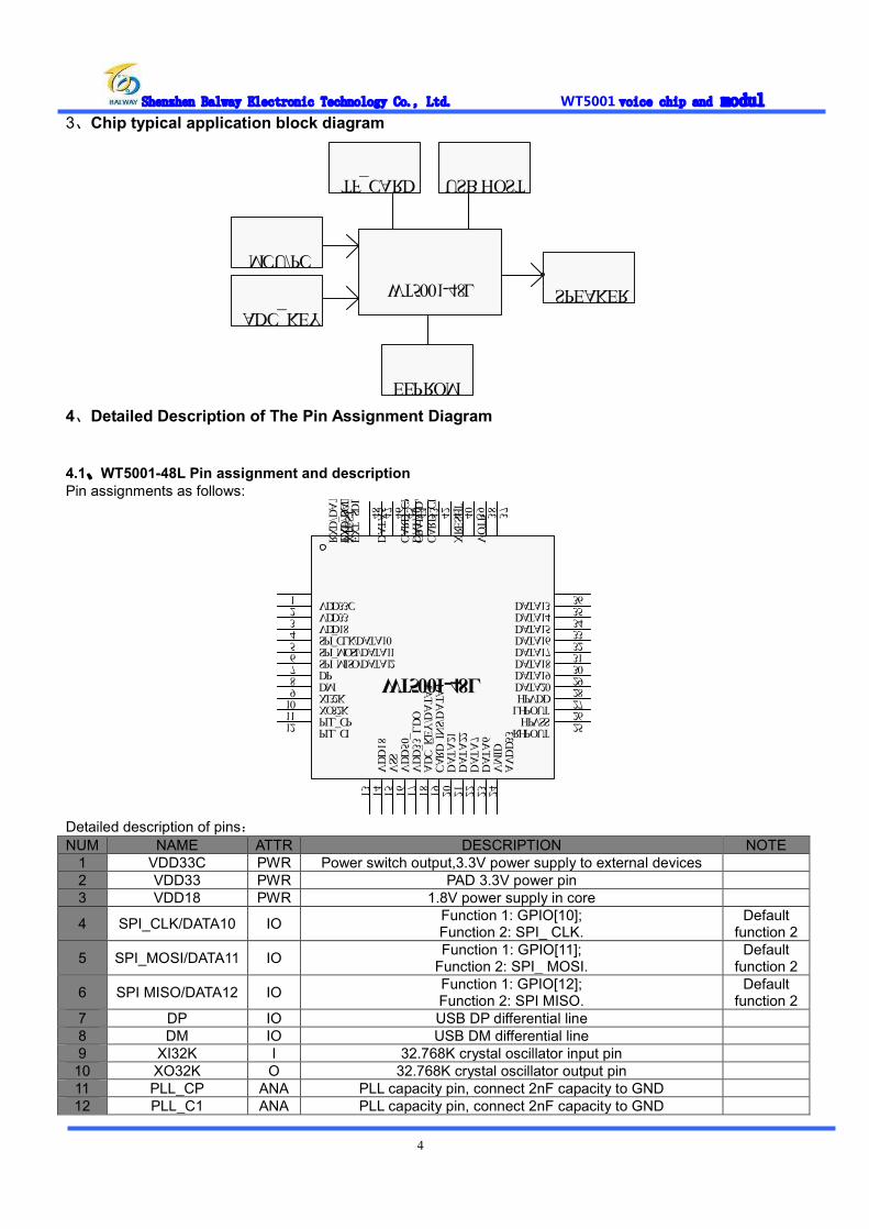
3、Chip typical application block diagram
WT5001-48LMCU/PC
SPEAKER
TF_CARD USB HOST
ADC_KEY
EEPROM
4、Detailed Description of The Pin Assignment Diagram
4.1、WT5001-48L Pin assignment and description Pin assignments as follows:
VDD33C1VDD332VDD183SPI_CLK/DATA104SPI_MOSI/DATA115SPI_MISO/DATA126DP7DM8XI32K9XO32K10PLL_CP11PLL_CI12
VDD18
13VSS
14VDD50
15VDD33_LDO
16ADC_KEY/DATA3
17CARD_INS/DATA4
18DATA21
19DATA22
20DATA7
21DATA6
22VMID
23AVDD33
24
RHPOUT 25HPVSS 26LHPOUT 27HPVDD 28DATA20 29DATA19 30DATA18 31DATA17 32DATA16 33DATA15 34DATA14 35DATA13 36
VOTP 37
XRESET
38
CARD_CLK
39
CRAD_DAT
40
CARD_CMD
41
DATA0 42
EXT_SDL/DATA1
43
EXT_SCL/DATA2
44
DATA5 45
TXD/DATA8
46
RXD/DATA9
47
XTEST 48
WT5001-48L
Detailed description of pins: NUM NAME ATTR DESCRIPTION NOTE
1 VDD33C PWR Power switch output,3.3V power supply to external devices 2 VDD33 PWR PAD 3.3V power pin 3 VDD18 PWR 1.8V power supply in core
4 SPI_CLK/DATA10 IO Function 1: GPIO[10]; Function 2: SPI_ CLK.
Default function 2
5 SPI_MOSI/DATA11 IO Function 1: GPIO[11]; Function 2: SPI_ MOSI.
Default function 2
6 SPI MISO/DATA12 IO Function 1: GPIO[12]; Function 2: SPI MISO.
Default function 2
7 DP IO USB DP differential line 8 DM IO USB DM differential line 9 XI32K I 32.768K crystal oscillator input pin
10 XO32K O 32.768K crystal oscillator output pin 11 PLL_CP ANA PLL capacity pin, connect 2nF capacity to GND 12 PLL_C1 ANA PLL capacity pin, connect 2nF capacity to GND
Shenzhen Balway Electronic Technology Co., Ltd. WT5001 voice chip and modul
5
13 VDD18_LDO PWR 1.8V power supply pin in core 14 VSS GND Package GND 15 VDD50 PWR LDO total power supply input, minimum can not be lower than 3.3V 16 VDD33_LDO PWR LDO 3.3V output, connect to 3.3V on the external
17 DATA3 IO function 1: GPIO[3]; function 2:ADC_KEY(standard MP3 key)
Default function 2
18 DATA4 IO Function 1: GPIO[4]; Function 2:CARD_INS(SD card detecting pin)
Default function 2
19 DATA21 IO Function 1: GPIO[21]; Function 2:A mode key;
Default function 2
20 DATA22 IO Function 1:GPIO[22]; Function 2:Press to copy function keys;
Default function 2
21 DATA7 IO GPIO[7]; 22 DATA6 IO GPIO[6]; 23 VMID ANA Decoupling capacitor connecting pin 24 AVDD33 PWR DAC analog power supply pin 25 RHPOUT ANA Headphone right channel output 26 HPVSS GND DAC high power GND 27 LHPOUT ANA Headphone left channel output 28 HPVDD PWR DAC high power supply,3.3V
29 DATA20 IO Function 1: GPIO[20]; Function 2:B mode key;
Default function 2
30 DATA19 IO Function 1: GPIO[19];
Function 2:One to one function key,corresponding to the address of the fourth song;
Default function 2
31 DATA18 IO Function 1: GPIO[18];
Function 2:One to one function key,corresponding to the address of the third song;
Default function 2
32 DATA17 IO Function 1: GPIO[17];
Function 2:One to one function key,corresponding to the address of the second song;
Default function 2
33 DATA16 IO Function 1: GPIO[16];
Function 2:One to one function key,corresponding to the address of the first song;
Default function 2
34 DATA15 IO Function 1: GPIO[15]; Function 2:BUSY indicate outout;
Default function 2
35 DATA14 IO Function 1: GPIO[14]; Function 2:One to one function key,switch cycle mode;
Default function 2
36 DATA13 IO Function 1: GPIO[13],24mA drive; 37 VOTP PWR OTP programming voltage,6.5Vinput,vacant when actual application 38 X_RESET_ I External reset pin 39 CARD_CLK IO SD/MMC/MSPRO clock bus 40 CARD_DAT IO SD/MMC/MSPRO data bus 41 CARD_CMD IO SD/MMC/MSPRO command bus
42 DATA0 IO Function 1: GPIO[0]; Function 2:Clock timer wake-up signal output, output 1 second high;
Default function 2
43 EXT_SDL /DATA1 IO Function 1: GPIO[1]; Function 2:EXT_SDL (EEPROM data bus);
Default function 2
44 EXT_SCL /DATA2 IO Function 1: GPIO[2]; Function 2:EXT_SCL (EEPROM clock bus);
Default function 2
45 DATA5 IO
Function 1: GPIO[5]; Function 2:Reset down into debug mode;
Function 3:Control sleep and awake;when DATA5 receive 2sec high level,IC enter into sleep mode;when IC in sleep mode, DATA5 receive
a high pluse,IC was awaken
Default function 3
46 DATA8 IO Function 1: GPIO[8]; Function 2: Serial port TXD.
Default function 2
47 DATA9 IO Function 1: GPIO[9]; Function 2: Serial port RXD.
Default function 2
48 X_TEST_MODE I High level enter to test mode ;low level enter functional mode
Shenzhen Balway Electronic Technology Co., Ltd. WT5001 voice chip and modul
6
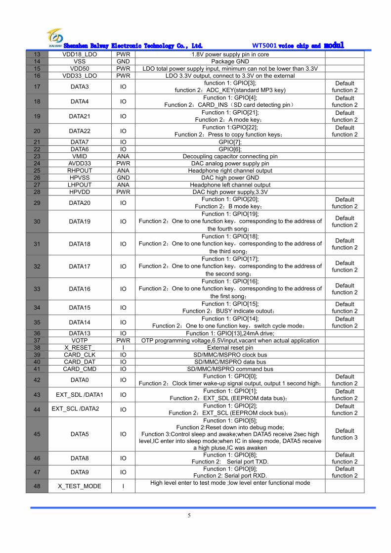
4.2、WT5001M01-16P Pin Assignment and Description Pin assignments as follows:(WT5001M01-16P V1.2)
RESET1AL2ROUT3LOUT4SPI_DI5SPI_DO6SPI_CLK7GND8 SPI_CEN 9TXD 10RXD 11DATA22 12ADC_KEY 13VDD33C 14BUSY 15VDD50 16
Detailed description of pin:
NUM NAME ATTR DESCRIPTION NOTE 1 RESET I External reset Reset when low trigger 2 AL ANA ADC audio output Can be connect to active speaker 3 ROUT ANA PWM audio output Can be connect to 1W8Ωspeaker 4 LOUT ANA PWM audio output Can be connect to 1W8Ωspeaker 5 SPI_DI IO SPI main output minor input data bus SPI download port 6 SPI_DO IO SPI main input minor output data bus SPI download port 7 SPI_CLK IO SPI clock bus SPI download port 8 GND GND GND 9 SPI_CEN IO SPI chip select bus SPI download port
10 TXD IO UART send bus 11 RXD IO UART receive bus 12 DATA22 Press to copy function keys 13 ADC_KEY IO ADC standard MP3 function key 14 VCC33 PWR LDO 3.3V output Output 3.3V to external 15 BUSY IO Indication output when the module is busy 16 VDD50 PWR Power supply port,DC5V
4.3、WT5001M02-28P Pin Assignment and Description Pin assignments as follows:(WT5001M02-28P V1.4)
DATA161GND2DATA173DATA184DATA195DATA56RESET7AL8ROUT9LOUT10SPI_DI11SPI_DO12SPI_CLK13GND14 SPI_CEN 15TXD 16RXD 17DATA22 18ADC_KEY 19VDD33C 20BUSY 21VDD50 22GND 23DATA14 24DM 25DP 26GND 27ENABLE 28
Detailed description of pin:
NUM NAME ATTR DESCRIPTION NOTE
1 DATA16 IO One to one function key,corresponding to the address of the first song;
2 GND Connect to TF socket shell
3 DATA17 IO One to one function key,corresponding to the address of the second song;
4 DATA18 IO One to one function key,corresponding to the
Shenzhen Balway Electronic Technology Co., Ltd. WT5001 voice chip and modul
7
address of the third song;
5 DATA19 IO One to one function key,corresponding to the address of the fourth song;
6 DATA5 IO
Control sleep and awake;when DATA5 receive 2sec high level,IC enter into sleep;when IC in
sleep mode,DATA5 receive a high pulse,IC was awaken
7 RESET I External reset Low trigger to reset 8 AL ANA ADC audio output Can be connect to active speaker 9 ROUT ANA PWM audio output Can be connect to 1W8Ωspeaker
10 LOUT ANA PWM audio output Can be connect to 1W8Ωspeaker 11 SPI_DI IO SPI main output minor input data bus SPI download port 12 SPI_DO IO SPI main input minor output data bus SPI download port 13 SPI_CLK IO SPI clock bus SPI download port 14 GND GND GND 15 SPI_CEN IO SPI chip select bus SPI download port 16 TXD IO UART send bus 17 RXD IO UART receive bus 18 DATA22 IO Press to copy function keys 19 ADC_KEY IO ADC standard MP3 function key 20 VDD33C PWR Module 3.3V output Output 3.3V to external 21 BUSY IO Indication output when the module is busy 22 VDD50 PWR Power supply port,DC5V 23 GND GND Connect to TF socket shell 24 DATA14 IO One to one function key ,switch play cycle mode 25 DM IO USB DM differential line 26 DP IO USB DP differential line
27 GND GND U disk power GND,connect to TF card socket shell
28 ENABLE IO Module amplifer enable pin, when vacant or keep high level, amplifer will be open; when connect to low level,amplifer will be closed
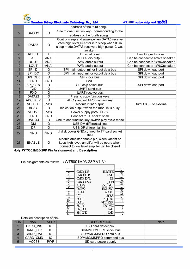
4.4、WT5001M03-28P Pin Assignment and Description
Pin assignments as follows:(WT5001M03-28P V1.3)
CARD_INS1CARD_CLK2CARD_DAT3CARD_CMD4VDD335DATA56RESET7AL8ROUT9LOUT10SPI_DI11SPI_DO12SPI_CLK13GND14 SPI_CEN 15TXD 16RXD 17DATA22 18ADC_KEY 19VDD33C 20BUSY 21VDD50 22EXT_SDL 23EXT_ SCL 24DM 25DP 26GND 27ENABLE 28
Detailed description of pin:
NUM NAME ATTR DESCRIPTION Note 1 CARD_INS IO (SD card detect pin) 2 CARD_CLK IO SD/MMC/MSPRO clock bus 3 CARD_DAT IO SD/MMC/MSPRO data bus 4 CARD_CMD IO SD/MMC/MSPRO command bus 5 VCC33 PWR SD card power supply

Shenzhen Balway Electronic Technology Co., Ltd. WT5001 voice chip and modul
8
6 DATA5 IO Control sleep and awake:when DATA5 receive 2sec high
level,IC enter into sleep mode; when IC in sleep mode,DATA5 receive a high pulse,IC is awaken
7 RESET I External reset Low trigger to reset
8 AL ANA ADC audio output Can be connect to active speaker
9 ROUT ANA PWM audio output Can be connect to 1W8Ωspeaker
10 LOUT ANA PWM audio output Can be connect to 1W8Ωspeaker
11 SPI_DI IO SPI main output minor input data bus SPI download port 12 SPI_DO IO SPI main input minor output data bus SPI download port 13 SPI_CLK IO SPI clock bus SPI download port 14 GND GND GND 15 SPI_CEN IO SPI chip select bus SPI download port 16 TXD IO UART send bus 17 RXD IO UART receive bus 18 DATA22 IO Press to copy function keys 19 ADC_KEY IO ADC standard MP3 functional key 20 VCC33 PWR Module 3.3V output 21 BUSY IO Indication output when the module is busy 22 VDD50 PWR Power supply port,DC5V 23 EXT_SDL IO EEPROM data bus; 24 EXT_SCL IO EEPROM data bus; 25 DM IO USB DM differential line 26 DP IO USB DP differential line 27 GND GND U disk GND
28 ENABLE IO Module amplifer enable pin,vacant or keep high
level,amplier will open;connect to low level ,amplifer will close
4.5、WT5001M04-14P Pin Assignment and Description Pin assignments as follows:
1234567891011121314
GNDSPI_CLKSPI_DOSPI_DILOUTROUT
SPI_CEN
ADC_KEYBUSYVDD50
DATA22RXDTXD
X_RESET
Detailed description of pin:
NUM NAME ATTR DESCRIPTION 备注
1 RESET I External reset Low trigger to reset
2 ROUT ANA PWM audio output Directly connect to 1W 8ohms speaker
3 LOUT ANA PWM audio output Directly connect to 1W 8ohms speaker
4 SPI_DI IO SPI main output minor input data bus SPI download port
5 SPI_DO IO SPI main input minor output data bus SPI download port

Shenzhen Balway Electronic Technology Co., Ltd. WT5001 voice chip and modul
9
6 SPI_CLK IO SPI clock bus SPI download port
7 GND GND GND
8 VDD50 PWR Power supply port,DC5V
9 BUSY IO Indication output when module is busy
10 ADC_KEY IO ADC standard function key
11 DATA22 Press to copy function key
12 RXD IO UART receive bus
13 TXD IO UART send bus
14 SPI_CEN IO SPI chip selection bus SPI download port
5、Detailed description of the functional operation The below function decription is for WT5001-48L, Module includes all the funcion of WT5001-48L,so please go to “4、Detailed Description of The Pin Assignment Diagram” to refer to module’s function . 5.1、BUSY indicate output
There is an output signal BUSY, when there are audios playing, the output will be high, and be low as normal.
5.2、Function detail of ADC standard key mode Key Operation Function and operation
PLAY Short press Play\Pause Long press Stop
NEXT Short press Select next song Long press Fast forward (when playing)
LAST Short press Select previous song Long press Fast reverse (when playing)
VOL+ Short press Volume increase Long press Volume increase rapidly
VOL- Short press Volume decrease Long press Volume decrease rapidly
5.3、Function setting description 5.3.1、Setting method
There is an iSound.mp3 document in SD card .Copy all mp3 files in SD card to SPI flash to operate, while all the configurations in iSound.mp3 file is updated to the SPI flash, the specific storing location as below. Note: you can open iSound.mp3 file on the computer by "WordPad", modify the setting parameters inside. Please don’t mistake the uppercase and lowercase of the"ISound.mp3" file name.
5.3.2、Function detail Setup as below: sp00//,Power-on Auto Play Setting. “sp”is lowercase, “00” indicates Power-on Non Auto Play, “01” indicates Power-on Auto Play; cl00//,Play Mode Setting. “cl” is lowercase, “00” indicates single track non cycle. “01” indicates single track cycle, “02” indicates all tracks cycle, “03” indicates play randomly; cfxx xx xx xx//, user defined. User can read the 4 bytes through serial port command . “cf” is lowercase,the “xx” following “cf” indicates 0~F hexadecimal character, “xx”indicates one byte, there is one blank space between two bytes,such as “cf23 A0 CE 78”; Through serial port send command “7E 02 C7 7E”, return “C7 23 A0 CE 78”(hexadecimal) Note: Followed “cf”, can maximum write 4 bytes character size, there is no blank space between cf and the first character,but there is one blank space between two bytes; if there are less than 4 bytes after “cf”,send code, still
Shenzhen Balway Electronic Technology Co., Ltd. WT5001 voice chip and modul
10
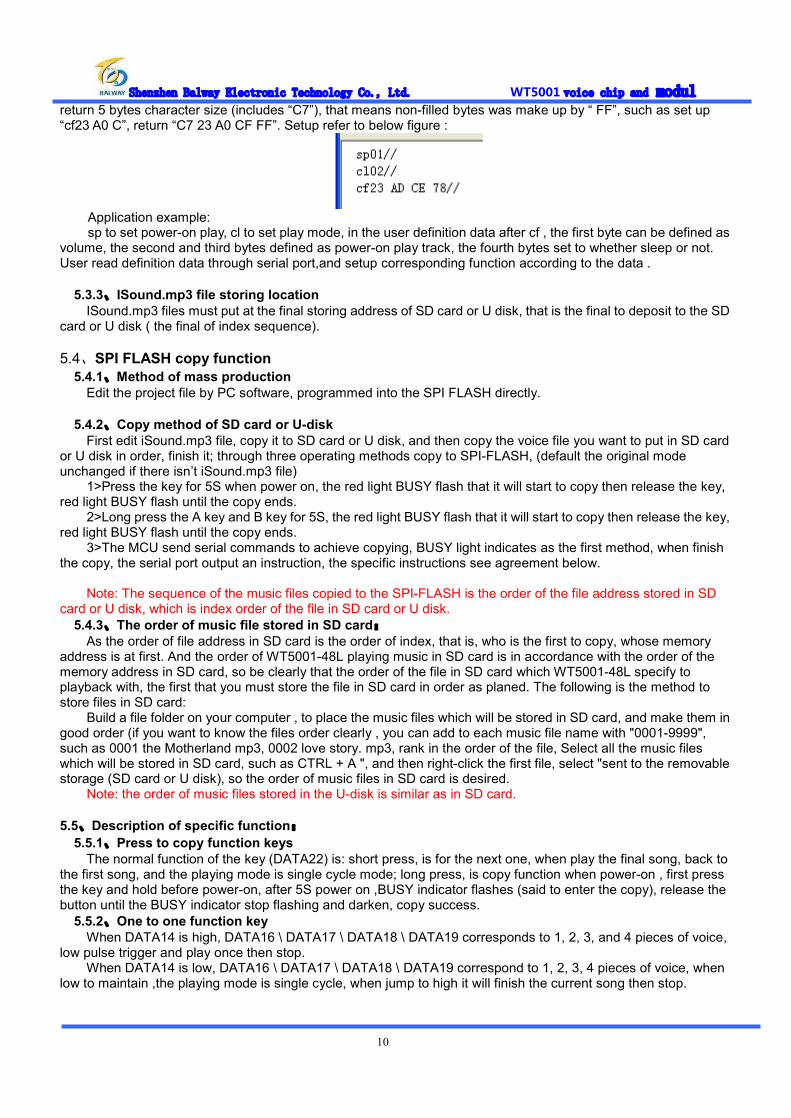
return 5 bytes character size (includes “C7”), that means non-filled bytes was make up by “ FF”, such as set up “cf23 A0 C”, return “C7 23 A0 CF FF”. Setup refer to below figure :
Application example: sp to set power-on play, cl to set play mode, in the user definition data after cf , the first byte can be defined as
volume, the second and third bytes defined as power-on play track, the fourth bytes set to whether sleep or not. User read definition data through serial port,and setup corresponding function according to the data .
5.3.3、ISound.mp3 file storing location ISound.mp3 files must put at the final storing address of SD card or U disk, that is the final to deposit to the SD
card or U disk ( the final of index sequence).
5.4、SPI FLASH copy function 5.4.1、Method of mass production
Edit the project file by PC software, programmed into the SPI FLASH directly.
5.4.2、Copy method of SD card or U-disk First edit iSound.mp3 file, copy it to SD card or U disk, and then copy the voice file you want to put in SD card
or U disk in order, finish it; through three operating methods copy to SPI-FLASH, (default the original mode unchanged if there isn’t iSound.mp3 file) 1>Press the key for 5S when power on, the red light BUSY flash that it will start to copy then release the key, red light BUSY flash until the copy ends. 2>Long press the A key and B key for 5S, the red light BUSY flash that it will start to copy then release the key, red light BUSY flash until the copy ends. 3>The MCU send serial commands to achieve copying, BUSY light indicates as the first method, when finish the copy, the serial port output an instruction, the specific instructions see agreement below.
Note: The sequence of the music files copied to the SPI-FLASH is the order of the file address stored in SD
card or U disk, which is index order of the file in SD card or U disk. 5.4.3、The order of music file stored in SD card:
As the order of file address in SD card is the order of index, that is, who is the first to copy, whose memory address is at first. And the order of WT5001-48L playing music in SD card is in accordance with the order of the memory address in SD card, so be clearly that the order of the file in SD card which WT5001-48L specify to playback with, the first that you must store the file in SD card in order as planed. The following is the method to store files in SD card: Build a file folder on your computer , to place the music files which will be stored in SD card, and make them in good order (if you want to know the files order clearly , you can add to each music file name with "0001-9999", such as 0001 the Motherland mp3, 0002 love story. mp3, rank in the order of the file, Select all the music files which will be stored in SD card, such as CTRL + A ", and then right-click the first file, select "sent to the removable storage (SD card or U disk), so the order of music files in SD card is desired. Note: the order of music files stored in the U-disk is similar as in SD card.
5.5、Description of specific function:
5.5.1、Press to copy function keys The normal function of the key (DATA22) is: short press, is for the next one, when play the final song, back to
the first song, and the playing mode is single cycle mode; long press, is copy function when power-on , first press the key and hold before power-on, after 5S power on ,BUSY indicator flashes (said to enter the copy), release the button until the BUSY indicator stop flashing and darken, copy success.
5.5.2、One to one function key When DATA14 is high, DATA16 \ DATA17 \ DATA18 \ DATA19 corresponds to 1, 2, 3, and 4 pieces of voice,
low pulse trigger and play once then stop. When DATA14 is low, DATA16 \ DATA17 \ DATA18 \ DATA19 correspond to 1, 2, 3, 4 pieces of voice, when
low to maintain ,the playing mode is single cycle, when jump to high it will finish the current song then stop.
Shenzhen Balway Electronic Technology Co., Ltd. WT5001 voice chip and modul
11
5.5.3、A、B mode function key A、B keys are set two different operating modes: Short press A key (DATA21) to select last song, long press A
key (DATA21) for 3S to set to A mode; short press B key (DATA20) to select next song, long press B key (DATA20) for 3S to set to B mode, the key is active low. When there is an EEPROM, it can remember the operating mode, identify the mode automatically when power on. As switching the mode, the light flashes indicate switching success and BUSY goes low.
Model A: auto play current song (Memory) each time when power-on, play it once and stop. Mode B: play the next one (Memory) each time when power-on, play it once and stop; when play the finial one
power-on, then start to play the first one when power-on next time. Note: when using A, B mode, there must be the EEPROM to memory power-down.
5.6、Description of storage 5.6.1、Stored format
The storage of SD card and U disk supports FAT16, FAT32 file system. 5.6.2、Memory power down
Memory store to the EEPROM when power down that is a standard function, memory power-down include volume value, the current playing song number and the setting of A, B mode referred below; when there isn’t external EEPROM, it will be no memory processing when power down ,but can not affect other functions;
5.7、Sleep and awake audio process function IC sleep and awake controlled through I/O port(DATA5), detail as below: Sleep: when DATA5 receive 2sec high level, IC enter into sleep mode; Awake sleep:When IC in sleep mode,when DATA5 receive a high pulse, IC was awaken
5.8、Process audio files
Support MP3, WAV format audio files. (in SPI-FLASH,do not support WAV format audio files); If the MP3 files store in SPI-FALSH, it should be lower bit rate MP3 format files. 6Kbps~320Kbps bit rate MP3 file and 8KHz~44.1KHz sample rate WAV file Note:Most voice quality of voice chip depend on audio itself sample rate and bit rate,WAV with more sample rate,the voice quality is better; MP3 with higher bit rate, the voice quality is better. It is recommand to use COOL EDIT PRO、ADOBE AUDITION、GOLDWAVE or TTPlayer such professional audio software to convert sample rate or bit rate.Then it can be realized good performance .
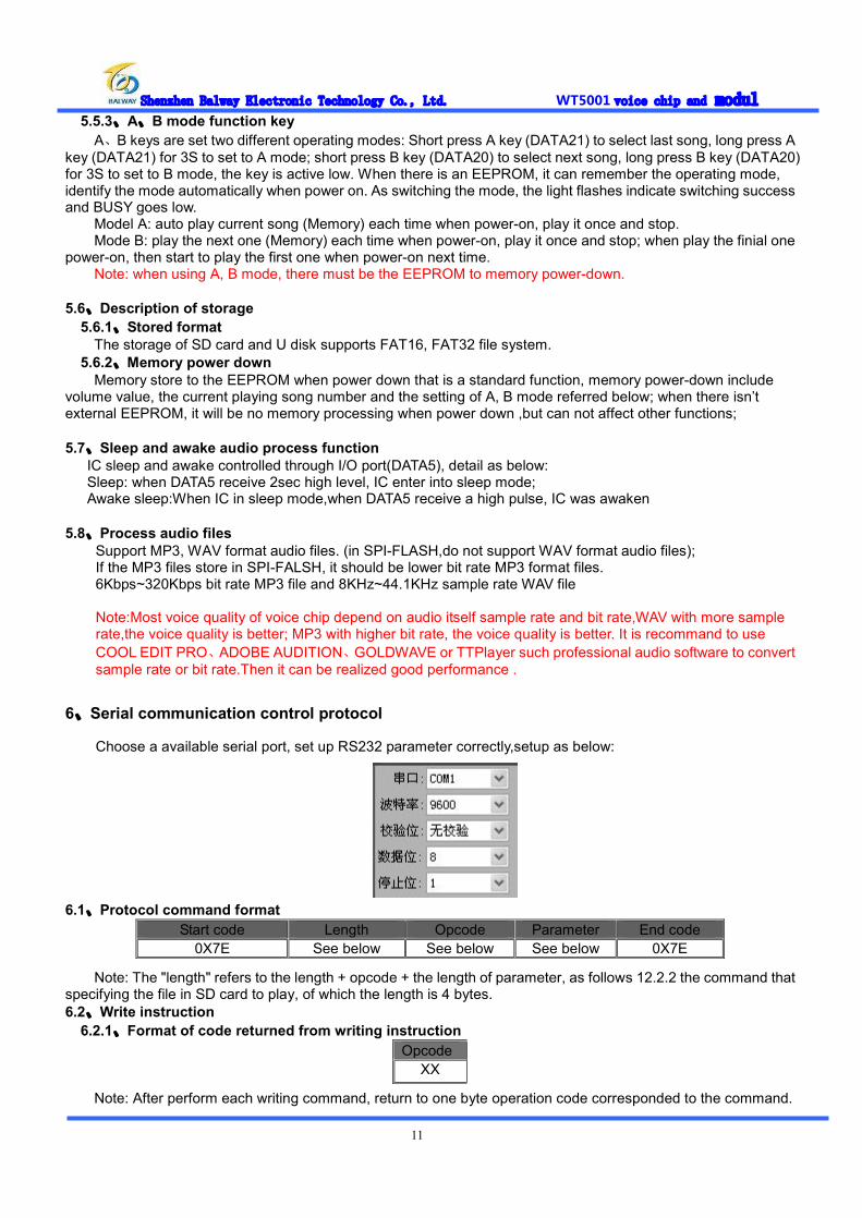
6、Serial communication control protocol
Choose a available serial port, set up RS232 parameter correctly,setup as below:
6.1、Protocol command format
Note: The "length" refers to the length + opcode + the length of parameter, as follows 12.2.2 the command that specifying the file in SD card to play, of which the length is 4 bytes. 6.2、Write instruction
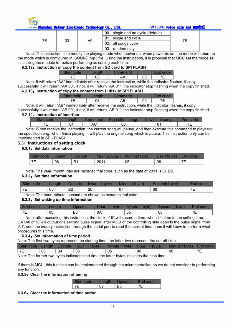
6.2.1、Format of code returned from writing instruction
Note: After perform each writing command, return to one byte operation code corresponded to the command.
Start code Length Opcode Parameter End code 0X7E See below See below See below 0X7E
Opcode XX

Shenzhen Balway Electronic Technology Co., Ltd. WT5001 voice chip and modul
12
6.2.2、Specify the files in SD card to play This command can specify the files in SD card to play, it doesn’t effect by the order of files stored.
Start code Length Command High bit of songs Low bit of songs End code 7E 04 A0 00 01 7E
6.2.3、Specify the files in SPI Flash to play This command can specify to the files operate only in SPI Flash.
Start code Length Command High bit of songs Low bit of songs End code 7E 04 A1 00 01 7E
6.2.4、Specify the files in U disk to play This command can specify the files to operate only in U disk.
Start code Length Command High bit of songs Low bit of songs End code 7E 04 A2 00 01 7E
6.2.5、Pause Start code Length Command End code
7E 02 A3 7E Sending the command first time to pause the music, send the data again, continue to play music from the
suspension. 6.2.6、Stop
Start code Length Command End code 7E 02 A4 7E
Sending the command to stop the current song. 6.2.7、Next song
Start code Length Command End code 7E 02 A5 7E
The instruction trigger to play the next song, when playing the first song, sending the command can trigger to play the final music.
6.2.8、Previous song Start code Length Command End code
7E 02 A6 7E The instruction trigger to play the previous song, when playing the final song, sending the command can
trigger to play the first song. 6.2.9、Volume control
The volume levels are total of 32, from 00 to 31, which 00 is mute, 31 is maximum volume. Start code Length Command Volume level End code
7E 03 A7 1F 7E The command in example is to send a maximum volume 31, this instruction can adjust the volume in real time,
and the volume can be in memory power-down (with EEPROM). 6.2.10、Combine to play
This command can specify certain files to play continuously in the current directory Start code Length Command High bit of songs Low bit of songs End code
7E 04 A8 00 01 7E The combination of playing is sending 10 groups or less music combination code to the WT5001-48L
continuously, WT5001-48L play the music according to the sequence of code received. Different from sending name to control directly is that the next code can not interrupt the playing until finish the current song , receive the command to do FIFO processing. Example : WT5001 continuously receive "7E 04 A8 00 08 7E ","7E 04 A8 00 06 7E ", "7E A8 04 00 07 7E "," 7E A8 04 00 04 7E "," 7E 04 A8 00 03 7E ","7E 04 A8 00 02 7E " six sets of data, WT2801-S specify to play SD files named" 0008.mp3 "," 0006.mp3 "," 0007.mp3 "," 0004.mp3 ","0003.mp3 "," 0002.mp3 "6 audio files in order.
Note: A, Before the combination of playing, if you want to play other mode of files stored, you must first send the specified storage mode playing command, the track in instructions fill in the first one of the combination of playing, and then send the tracks behind in the instructions, to realize combine to play. B, Combination of playing only in the non-cyclic mode, is invalid in the single cycle mode or all songs cycle mode,; C, The continuous combination is maximum 10 groups. During playback, if there is a new command it can be interrupted, and implement the new command.
6.2.11、Set playing mode Start code Length Command Parameter End code
Shenzhen Balway Electronic Technology Co., Ltd. WT5001 voice chip and modul
13
7E 03 A9
00:single and no cycle (default)
7E 01:single and cycle 02:all songs cycle 03:random play
Note: The instruction is to modify the playing mode when power on, when power down, the mode will return to the mode which is configured in iSOUND.mp3 file. Using the instructions, it is proposal that MCU set the mode as initializing the module to realize performing as setting each time.
6.2.12、Instruction of copy the content from SD card to SPI FLASH Start code Length Command End code
7E 03 AA 00 7E Note: It will return "AA" immediately after receive the instruction, while the indicator flashes, if copy
successfully it will return "AA 00", if not, it will return "AA 01"; the indicator stop flashing when the copy finished. 6.2.13、Instruction of copy the content from U disk to SPI FLASH
Start code Length Command End code 7E 03 AB 00 7E
Note: it will return "AB" immediately after receive the instruction, while the indicator flashes, if copy successfully it will return "AB 00", if not, it will return "AB 01"; the indicator stop flashing when the copy finished.
6.2.14、Instruction of insertion Start code Length Command High bit of songs Low bit of songs End code
7E 04 AC 00 01 7E Note: When receive the instruction, the current song will pause, and then execute this command to playback
the specified song, when finish playing, it will play the original song which is pause. This instruction only can be implemented in SPI- FLASH. 6.3、Instructions of setting clock
6.3.1、Set data information
Note: The year, month, day are hexadecimal code, such as the data of 2011 is 07 DB. 6.3.2、Set time information
Note: The hour, minute, second are shown as hexadecimal code. 6.3.3、Set waking up time information
Note: after executing this instruction, the clock of IC will record a time, when it’s time to the setting time, DATA0 of IC will output one second pulse signal; after MCU of the controlling side detects the pulse signal from INT, sent the inquiry instruction through the serial port to read the current time, then it will know to perform what procedures this time.
6.3.4、Set information of time period Note: The first two bytes represent the starting time, the latter two represent the cut-off time.
Note: The former two bytes indicates start time,the latter bytes indicates the stop time If there is MCU, this function can be implemented through the microcontroller, so we do not consider to performing any function. 6.3.5、Clear the information of timing
6.3.6、Clear the information of time period
Start code Length Opcode Year(2bytes) Month(1byte) Day (1byte) End code 7E 06 B1 2011 05 08 7E
Start code Length Opcode Hour(1byte) Minute (1byte) Second(1byte) End code 7E 05 B2 20 07 08 7E
Start code Length Opcode Hour (1byte) Minute (1byte) Second (1byte) End code 7E 05 B3 0A 05 08 7E
Start code Length Opcode Hour (1byte) Minute (1byte) Hour (1byte) Minute(1byte) End code 7E 06 B4 06 05 06 08 7E
Start code Length Opcode End code 7E 02 B5 7E

Shenzhen Balway Electronic Technology Co., Ltd. WT5001 voice chip and modul
14
6.4、The command of reading operation
6.4.1、Read the current volume value Start code Length Command End code 7E 02 C1 7E
The format returned: Opcode Return value
0XC1 Volume value(00-1F)
6.4.2、Read the current playing state Start code Length Command End code 7E 02 C2 7E
The format returned: Opcode Return value
0XC2 01:Play 02:Stop; 03:Pause
6.4.3、Read the total number of files in SPI Flash Start code Length Command End code 7E 02 C3 7E
The format returned: Opcode Return value 0XC3 Total number of files
6.4.4、Read the total number of files in SD card
Start code Length Command End code 7E 02 C4 7E
The format returned: Opcode Return value 0XC4 Total number of files
6.4.5、Read the total number of files in U disk Start code Length Command End code 7E 02 C5 7E
The format returned: Opcode Return value 0XC5 Total number of files
6.4.6、Read the current audio file name Start code Length Command End code 7E 02 C6 7E
The format returned: Opcode High bit of files number Low bit of files number 0XC6 XX XX
6.4.7、Read iSound.mp3 file “cf”character Start code Length Command End code 7E 02 C7 7E
The format returned:
OPcode Return value
0XC7 XX XX XX XX
Note:Return code : “C7 23 A0 CE FF”, every bit is hexadecimal character, indicates that every bit is among “0-F” ;if the “cf” in iSound.mp3 only has two or less than four bytes,then will still return four bytes character, but except for iSound.mp3 character is set, the others use “F” take place; for example “cf23 AD” , then return “C7 23 AD FF FF”.
Start code Length Command End code 7E 02 B6 7E
Shenzhen Balway Electronic Technology Co., Ltd. WT5001 voice chip and modul
15
6.4.8、Read the current data information
The format returned:
6.4.9、Read the current time information
The format returned:
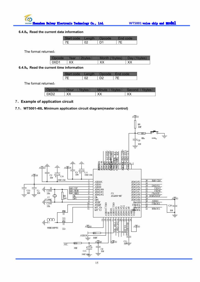
7、Example of application circuit
7.1、WT5001-48L Minimum application circuit diagram(master control)
C5104C3
104
VDD33CVDD33
C7104
VDD18
C20
222C21
223
L1
600R/100mH
Y132.768K
C1833P
C1933P
R92M
C8104
VDD18
VDD50 VDD33
C16
104
C17106
VDD33
DPDM
ADC_KEY
CARD_INT
LHPOUT
RHPOUT
VDD33
SPI0_CLKSPI0_MOSISPI0_MISO
SPI0_CEN
CARD_CMD
CARD_DAT
CARD_CLK
R410K
VDD33
C6104
R11
100KVDD33C EX
TRIGGER
VDD33
VDD33C1VDD332VDD183XDATA104XDATA115XDATA126DP7DM8XI32K9XO32K10PLL_CP11PLL_C112
VDD18_LDO
13VSS
14VDD50
15VDD33_LDO
16XDATA3
17XDATA4
18XDATA21
19XDATA22
20XDATA7
21XDATA6
22VMID
23AVDD33
24
RHPOUT 25HPVSS 26LHPOUT 27HPVDD 28XDATA20 29XDATA19 30XDATA18 31XDATA17 32XDATA16 33XDATA15 34XDATA14 35XDATA13 36
VOTP 37
XRESET
38
CARD_CLK
39
CARD_DAT
40
CARD_CMD
41
XDATA0
42
XDATA1
43
XDATA2
44
XDATA5
45
XDATA8
46
XDATA9
47
XTEST 48
U3WT5001-48L
P32/TXD
P31/RXD
R10
10R
C11100U/10V
C10100U/10V
C12100U/10V
DOWN/VOL-
A
EXT_SDL
EXT_SCL
VCC
RELAY
trigger
B
LED-G
UP/VOL+C15106
LED-R
DATA15
R1*
0R*
K1*
reset*
Start code Length Opcode End code 7E 02 D1 7E
Opcode Year (2bytes) Month (1bytes) Day (1bytes) 0XD1 XX XX XX
Start code Length Opcode End code 7E 02 D2 7E
Opcode Hour (1bytes) Minute(1bytes) Second(1bytes) 0XD2 XX XX XX

Shenzhen Balway Electronic Technology Co., Ltd. WT5001 voice chip and modul
16
7.2、WT5001M01-16P Minimum application circuit diagram
RESET1AL2ROUT3LOUT4SPI_DI5SPI_DO6SPI_CLK7GND8 SPI_CEN 9TXD 10RXD 11DATA22 12ADC_KEY 13VCC33 14BUSY 15VDD50 16
A?
WT5001M01-16P
S1VOL+
S2VOL-
S3FOLDER1
S4FOLDER2
S5FOLDER3
R8200K 1%R9150K 1%
R1615K 1%
R10100K 1%R1551K 1%
ADC_KEY
VDD50
LS?
SPEAKER
7.3、WT5001M02-28P Minimum application circuit diagram
ADC_KEY
VDD50
LS?
SPEAKER
S1VOL+
S2VOL-
S3UP
S4DOWN
S5PLAY/PAUSE
R8200K 1%R9150K 1%
R1615K 1%
R10100K 1%R1551K 1%
DATA161GND2DATA173DATA184DATA195DATA56RESET7AL8ROUT9LOUT10SPI_DI11SPI_DO12SPI_CLK13GND14 SPI_CEN 15TXD 16RXD 17DATA22 18ADC_KEY 19VDD33C 20BUSY 21VDD50 22GND 23DATA14 24DM 25DP 26GND 27ENABLE 28
WT5001M02-28P
7.4、WT5001M03-28P Minimum application circuit diagram
ADC_KEY
VDD50
LS?
SPEAKER
S1VOL+
S2VOL-
S3FOLDER1
S4FOLDER2
S5FOLDER3
R8200K 1%R9150K 1%
R1615K 1%
R10100K 1%R1551K 1%
CARD_INS1CARD_CLK2CARD_DAT3CARD_CMD4VDD335DATA56RESET7AL8ROUT9LOUT10SPI_DI11SPI_DO12SPI_CLK13GND14 SPI_CEN 15TXD 16RXD 17DATA22 18ADC_KEY 19VDD33C 20BUSY 21VDD50 22EXT_SDL 23EXT_ SCL 24DM 25DP 26GND 27ENABLE 28
WT5001M03-28P 7.5、WT5001M04-14P Minimum application circuit diagram
1234567891011121314
WT5001M04-14P
GNDSPI_CLKSPI_DOSPI_DILOUTROUT
SPI_CEN
ADC_KEYBUSYVDD50
DATA22RXDTXD
X_RESET
ADC_KEY
VDD50
VOL+S2
VOL-S3
UPS4
DOWNS5
PLAY/PAUSE
R8200K 1%R9150K 1%
R1615K 1%
R10100K 1%R1551K 1%
LS?
SPEAKER
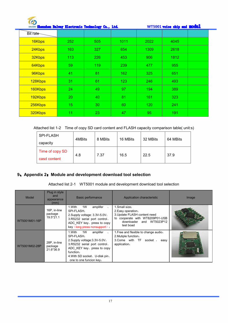
8、Appendix 1:SPI-FLASH capacity corresponding parameter Attached list 1-1 WT5001 module FLASH capacity and time swap table(unit:s)
Capacity 4MBits 8MBits 16MBits 32MBits 64MBits
Shenzhen Balway Electronic Technology Co., Ltd. WT5001 voice chip and modul
17
Bit rate
16Kbps 252 505 1011 2022 4045
24Kbps 163 327 654 1309 2618
32Kbps 113 226 453 906 1812
64Kbps 59 119 239 477 955
96Kbps 41 81 162 325 651
128Kbps 31 61 123 246 493
160Kbps 24 49 97 194 389
192Kbps 20 40 81 161 323
256Kbps 15 30 60 120 241
320Kbps 11 23 47 95 191
Attached list 1-2 Time of copy SD card content and FLASH capacity comparison table( unit:s)
SPI-FLASH
capacity 4MBits 8 MBits 16 MBits 32 MBits 64 MBits
Time of copy SD
casd content 4.8 7.37 16.5 22.5 37.9
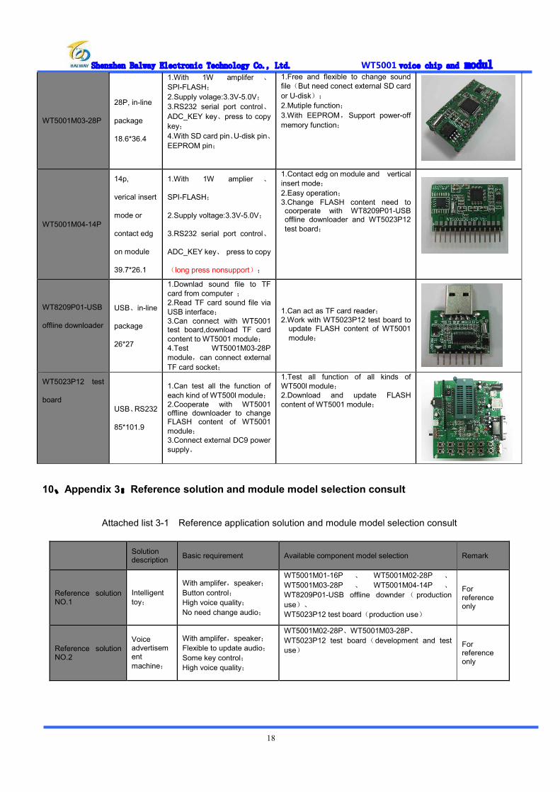
9、Appendix 2:Module and development download tool selection
Attached list 2-1 WT5001 module and development download tool selection
Model
Plug in style and
appearance (mm)
Basic performance Application characteristic Image
WT5001M01-16P
16P, in-line package 19.5*21.1
1.With 1W amplifer 、
SPI-FLASH; 2.Supply voltage: 3.3V-5.0V; 3.RS232 serial port control、ADC_KEY key、press to copy key(long press nonsupport);
1.Small size; 2.Easy operation; 3.Update FLASH content need to cooperate with WT8209P01-USB
downloader and WT5023P12 test boad
WT5001M02-28P 28P, in-line package 21.6*36.9
1.With 1W amplifer 、
SPI-FLASH; 2.Supply voltage:3.3V-5.0V; 3.RS232 serial port control、ADC_KEY key、press to copy function; 4.With SD socket、U-disk pin、one to one funcion key;
1.Free and flexible to change audio; 2.Mutiple function; 3.Come with TF socket , easy application;
Shenzhen Balway Electronic Technology Co., Ltd. WT5001 voice chip and modul
18
WT5001M03-28P
28P, in-line
package
18.6*36.4
1.With 1W amplifer 、
SPI-FLASH; 2.Supply volage:3.3V-5.0V; 3.RS232 serial port control、ADC_KEY key、press to copy key; 4.With SD card pin、U-disk pin、EEPROM pin;
1.Free and flexible to change sound file(But need conect external SD card or U-disk); 2.Mutiple function; 3.With EEPROM,Support power-off memory function;
WT5001M04-14P
14p,
verical insert
mode or
contact edg
on module
39.7*26.1
1.With 1W amplier 、
SPI-FLASH;
2.Supply voltage:3.3V-5.0V;
3.RS232 serial port control、
ADC_KEY key、 press to copy
(long press nonsupport);
1.Contact edg on module and vertical insert mode; 2.Easy operation; 3.Change FLASH content need to coorperate with WT8209P01-USB offline downloader and WT5023P12 test board;
WT8209P01-USB
offline downloader
USB、in-line
package
26*27
1.Downlad sound file to TF card from computer ; 2.Read TF card sound file via USB interface; 3.Can connect with WT5001 test board,download TF card content to WT5001 module; 4.Test WT5001M03-28P module,can connect external TF card socket;
1.Can act as TF card reader; 2.Work with WT5023P12 test board to
update FLASH content of WT5001 module;
WT5023P12 test
board USB、RS232
85*101.9
1.Can test all the function of each kind of WT500l module; 2.Cooperate with WT5001 offline downloader to change FLASH content of WT5001 module; 3.Connect external DC9 power supply。
1.Test all function of all kinds of WT500l module; 2.Download and update FLASH content of WT5001 module;
10、Appendix 3:Reference solution and module model selection consult
Attached list 3-1 Reference application solution and module model selection consult
Solution description Basic requirement Available component model selection Remark
Reference solution NO.1
Intelligent toy;
With amplifer,speaker; Button control; High voice quality; No need change audio;
WT5001M01-16P 、 WT5001M02-28P 、
WT5001M03-28P 、 WT5001M04-14P 、
WT8209P01-USB offline downder ( production use)、 WT5023P12 test board(production use)
For reference only
Reference solution NO.2
Voice advertisement machine;
With amplifer,speaker; Flexible to update audio; Some key control; High voice quality;
WT5001M02-28P、WT5001M03-28P、 WT5023P12 test board(development and test use)
For reference only

Shenzhen Balway Electronic Technology Co., Ltd. WT5001 voice chip and modul
19
Reference solution NO.3
Voice prompts
Can take amplifer and speaker; Flexible to update audio; Some control I/O port; High voice quality;
WT5001M02-28P 、 WT5001M03-28P 、
WT8209P01-USB offline downloader、 WT5023P12 test board(development and test use)
For reference only
Reference solution NO.4
Electroni voice greeting card;
With amplifer and speaker; Small thickness; Play simple audio;no need update voice; High voice quality;
WT5001M04-14P、 WT8209P01-USB offline downloader(production use)、 WT5023P12 test board(production and test use)
For reference only

Shenzhen Balway Electronic Technology Co., Ltd. WT5001 voice chip and modul
20
11、Manual Version Record Version Date Description V1.0 2011-12-13 Original version
V1.1 2011-12-22 Add appendix:SPI-FLASH capactiy reference parameter
V1.2 2012-02-14 1、Add WT5001M04-14P“pin assignment description”and application circuit; 2、Add RS232 parameter setting; 3、Modify“6.3.1 set data information”and“6.3.2 set time information”command description; 4、Add WT5001-48L voice chip minimum application circuit diagram(master control); 5、Modify“5.7 Process audio files”description: 6、Add“Appendix 2:module and development download tool model selection”and“Appendix 3:reference solution and module model selection reference”description.
V1.3 2012-03-13 1、In iSoud.mp3 setting,add “cf”character information setting; 2、Add read“cf”character information serial command“7E 02 C7 7E ”; 3、Add sleep and awake function;Through DATA5 control; 4、Modify module pin definition,change pin“6”and“28” of WT5001M02 and WT5001M03 to “DATA5” and“ENABLE”; 5、Modify corresponding application circuit: