The Laboratory of Computer Communication and Networking Broadband Access Networks Simulator (BANS)
37
The Laboratory of The Laboratory of Computer Communication Computer Communication and Networking and Networking Broadband Access Broadband Access Networks Simulator Networks Simulator (BANS) (BANS)
-
date post
21-Dec-2015 -
Category
Documents
-
view
216 -
download
0
Transcript of The Laboratory of Computer Communication and Networking Broadband Access Networks Simulator (BANS)

The Laboratory of Computer The Laboratory of Computer Communication and Communication and
NetworkingNetworking
Broadband Access Broadband Access Networks Simulator Networks Simulator
(BANS)(BANS)

Project TeamProject Team
Submitted by: Alex Kogan sakogan@t2 Technion
Alex Reitbort sreit@t2 Technion
Alex Umansly salexu@t2 Technion
Instructor: Chen Genossar [email protected] Optical Access
Supervisor: Itai Dabran idabran@cs Technion

Project GoalProject Goal
Develop a simulator of a broadband access network, in order to simulate real broadband access networks behavior and find bottlenecks of the network.

BackgroundBackground
For the past several years, the computer communication industry has witnessed an explosive growth in the demand for non-voice types of services, like movies, video-conferencing, etc.
For these fixed and mobile services, currently existing access networks can’t offer the enough bandwidth to meet the demands.
One of the biggest challenges currently network operators are facing, is to find cost effective solution for supporting broadband access, both fixed and wireless.

Background (Cont.)Background (Cont.)
The key factor here is the need to find solution that is able to satisfy both residential and business customers.
These two sectors have considerably different requirements in terms of both service basket and bandwidth usage.
It may be that the separate networks are required to support those requirements, but there could be a significant advantage in terms of economies of the scales and network manageability if a single solution can be found.

Background (Cont.)Background (Cont.)

Background (Cont.)Background (Cont.)
In the previous figure, the final connection is depending on the services provided.
Example:
For Video-on-Demand (VoD) service, the final connection could use twisted pair by VDSL/ADSL technologies. Or instead we can use coaxial cable.

Background (Cont.)Background (Cont.)

Background (Cont.)Background (Cont.)
The previous figure shows the possible FTTH/FTTC/FTTB/FTTN architectures for comparison. For example, in FTTC architecture, the signals from the Center Office (CO) are routed through to an ONU by fiber.
It needs to deploy the fiber connection to every home/Curb/Building/Node.
Compared with deploying fiber, free space optical mesh architecture is more easily to deploying and more cost-effective.

Project DescriptionProject Description
The simulated network is defined as a graph consists of arcs and nodes.
The arcs represent the physical connections.
The nodes represent servers or users. Simulator provides special “Internet” nodes,
which will represent gateways to the Internet.
Project provides a GUI interface in order to define the network topology, links, servers, users and their features.

BANS GUI InterfaceBANS GUI Interface
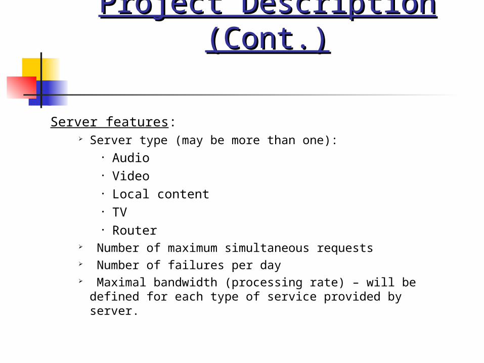
Project Description (Cont.)Project Description (Cont.)
Server features: Server type (may be more than one):
• Audio• Video• Local content• TV• Router
Number of maximum simultaneous requests Number of failures per day Maximal bandwidth (processing rate) – will be
defined for each type of service provided by server.

Server Properties WindowServer Properties Window

Project Description (Cont.)Project Description (Cont.)
User features: User upload/download stream per hour
(Mb/s) Target of upload/download stream –
Video server, Internet surfing, etc. – is defined for each two hours.
It is possible to define (and save/remove) network-using patterns and to ascribe each of them to users. Such patterns define the previous two features.
Designated server for each type of service

User Properties WindowUser Properties Window

Project Description (Cont.)Project Description (Cont.)
Link features: Maximal Bandwidth Number of failures per day (when the link
is down) Blocking service - the acceptable
percentage of the data that is actually transmitted through the link from the total data that was intended to be sent through the link (due to the limitation of link’s bandwidth, some of the data might get lost)
Cost (between 1 and 16)

Link Properties WindowLink Properties Window

Project Description (Cont.)Project Description (Cont.)
Project provides option of saving/loading current network topology into/from file. In addition, it will be possible to import network from previously saved file into the current topology or export part of the network into file.
Thus, some typical network topologies (tree, mesh, bus) could be prepared ahead for more convenient work in the future.

Project Description (Cont.)Project Description (Cont.)
Project provides different types of simulations on current network:
Simulation over selected time period Simulation until first failure.
The failure will be defined as one of the following:
• Link bandwidth exceeded• Server bandwidth exceeded (for some type
of service)• Network (part of users) inaccessible
(because of link/server failure as a result of predefined failure parameters).
The result of the simulation will be displayed graphically and textually.

Run Simulation WindowRun Simulation Window

Simulation Results Simulation Results WindowWindow

AlgorithmsAlgorithms
The simulator implements number of algorithms in order to simulate the real traffic in network.
Shortest Single Source Path (SSSP):
The simulator needs this algorithm to find the shortest path between some user and server. Actually, it comes to simulate the work of OSPF since all links and their costs are known in the network.
We have chosen to implement Dijkstra algorithm.

Algorithms (Cont.)Algorithms (Cont.)
Find Designated Server:
This algorithm decides which router in the network will be chosen to supply requested service to the user and which path to it will be taken. It uses previously defined SSSP algorithm in order to make path choice optimal.
This algorithms provides full support for all options of the simulation. In case that designatedserver was chosen for some user, this algorithm should be called with list of servers thatcontains only the designated server. Otherwise, all servers in the network should be delivered.

Algorithms (Cont.)Algorithms (Cont.)
There is an option to find the server with closest path only (if user has chosen appropriate option in Simulation Setting dialog or run the simulation with this option as default).
Actually,this approach represents the method that is employed in most current routing algorithms.
In this case, a server that provides needed service with shortest path from the user, is chosen and returned from the algorithm.

Algorithms (Cont.)Algorithms (Cont.)
This algorithm tries to locate the nearest accessible server that can provide needed service with required bandwidth to user.
In case that some accessible server is found, but path to it is overloaded (can not allow additional traffic with required bandwidth), some link on its path is removed and new paths are recalculated.
This is done in order to allow traffic on another cheap path.

Algorithms (Cont.)Algorithms (Cont.)
The same is true regarding routers in the chosen path- if some router is overloaded and can not accept more traffic, then another, more free path is chosen after the overloaded router is taken out of the network.
After some path was found (or failure was reported if any path was not chosen), all components taken from network are placed back in order to try use them for other users and services.

Algorithms (Cont.)Algorithms (Cont.)
If any path will not be found (or the shortest path in case of “Do Not Look For Alternative Paths/Servers” option) available, failure will be reported in simulation results under one of three reasons:
Server is unreachable (in case any server was found) Link failure (in case path was found, but some link was
overloaded) Router failure (in case some path was found, but some
router on it was not capable of delivering requested traffic)
Two last failures might be reported for the same user, because both of them represent some bottleneck in the network.

Algorithms (Cont.)Algorithms (Cont.)
Find Designated Web Gateway: This algorithm decides which gateway in the network will be chosen to supply Internet requests (i.e. requests generated by user while surfing in the Internet) from user.
Its principles are very similar to the previously discussed algorithm – the main difference is that we do nor need to check if gateway can accept new user and provide required bandwidth, since we assume that comparing to local servers, backbone gateways are very powerful machines with unlimited resources (however, all local links and routers are limited by the predefined resources, thus it is still possible that network will fail to provide Internet service to some user ).
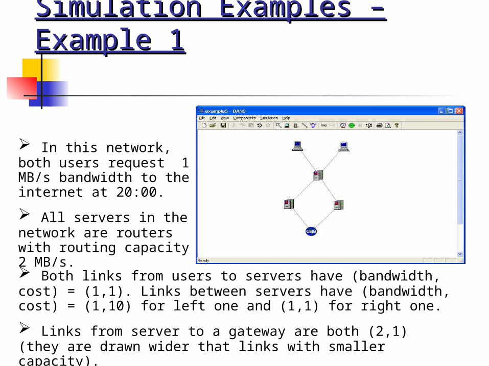
Simulation Examples – Simulation Examples – Example 1Example 1
Both links from users to servers have (bandwidth, cost) = (1,1). Links between servers have (bandwidth, cost) = (1,10) for left one and (1,1) for right one.
Links from server to a gateway are both (2,1) (they are drawn wider that links with smaller capacity).
In this network, both users request 1 MB/s bandwidth to the internet at 20:00.
All servers in the network are routers with routing capacity 2 MB/s.

Example 1 (Cont.)Example 1 (Cont.)
We expect that the traffic will go on the cheaper path first, and only if there is no choice - on the more expensive. The results of the simulation are as following:
There is a path between each user and gateway,which can carry requested bandwidth, and thus there are no failures in the network.

Example 1 (Cont.)Example 1 (Cont.)
When we set bandwidth of the righter link from user to server to 0.5MB/s, we discover failure of this link, since it can't provide needed bandwidth and user have no any other available paths.

Example 1 (Cont.)Example 1 (Cont.)
As we can see, results are no different from what we expected.
Since there is no path that can provide required bandwidth from users to internet gateway, then one of the links in available path will fail.
This has to be a link between servers since they are the one who can't provide needed bandwidth.
Failed right link, because it has lower cost, thus routers tried to send data through
In order to fix the network, we can, for example, change bandwidth of righter link between servers from 0.5 to 1, as suggested, or decrease its blocking service.

Simulation Simulation ExamplesExamples – – Example 2Example 2
In this example each user want to get 1 MB/s of audio each hour except 14:00, then they want 2 MB/s of audio.
Left server is router and right server is audio, each with maximum users 5 and maximum bandwidth 10.
Links from users to router are (3,1) and from router to audio (9,1).
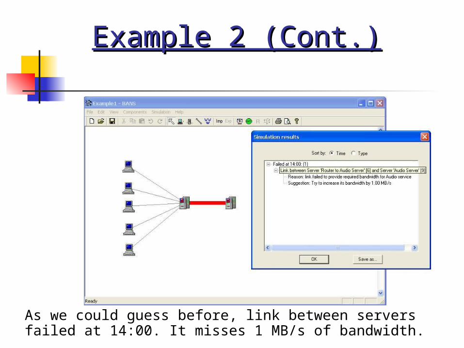
Example 2 (Cont.)Example 2 (Cont.)
As we could guess before, link between servers failed at 14:00. It misses 1 MB/s of bandwidth.

Simulation Examples – Simulation Examples – Example 3Example 3
In this example each user wants to get 1 MB/s of internet each hour.
All serves are routers with maximum users 1 and maximum bandwidth 1.
All links are (1,1).
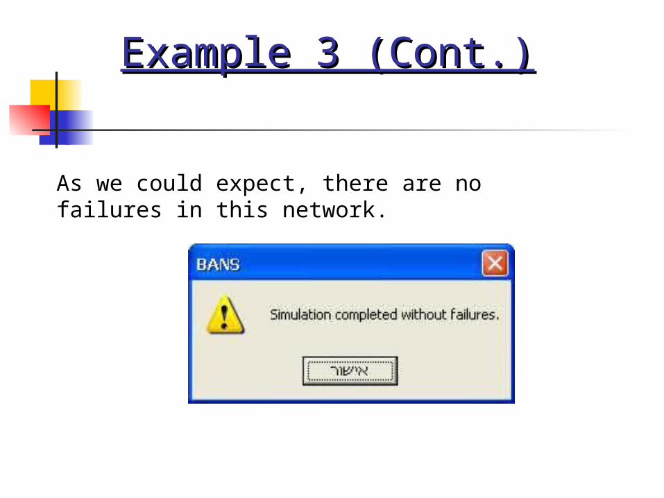
Example 3 (Cont.)Example 3 (Cont.)
As we could expect, there are no failures in this network.

Simulator Presentation
And now – to the real thing (simulator) …