
THE JPEG2000 STILL IMAGE CODING SYSTEM: AN …dsmc.eap.gr/pubs/ans-b16.pdf · THE JPEG2000 STILL...
25
THE JPEG2000 STILL IMAGE CODING SYSTEM: AN OVERVIEW Charilaos Christopoulos 1 Senior Member, IEEE, Athanassios Skodras 2 Senior Member, IEEE, and Touradj Ebrahimi 3 Member, IEEE 1 Media Lab, Ericsson Research Corporate Unit, Ericsson Radio Systems AB, S-16480 Stockholm, Sweden Email: [email protected] 2 Electronics Laboratory, University of Patras, GR-26110 Patras, Greece Email: [email protected] 3 Signal Processing Laboratory, EPFL, CH-1015 Lausanne, Switzerland Email: [email protected] Abstract -- With the increasing use of multimedia technologies, image compression requires higher performance as well as new features. To address this need in the specific area of still image encoding, a new standard is currently being developed, the JPEG2000. It is not only intended to provide rate-distortion and subjective image quality performance superior to existing standards, but also to provide features and functionalities that current standards can either not address efficiently or in many cases cannot address at all. Lossless and lossy compression, embedded lossy to lossless coding, progressive transmission by pixel accuracy and by resolution, robustness to the presence of bit-errors and region-of-interest coding, are some representative features. It is interesting to note that JPEG2000 is being designed to address the requirements of a diversity of applications, e.g. Internet, color facsimile, printing, scanning, digital photography, remote sensing, mobile applications, medical imagery, digital library and E-commerce. Keywords -- JPEG, JPEG2000, color image coding, data compression, source coding, subband coding, wavelet transform. I. INTRODUCTION Since the mid-80s, members from both the International Telecommunication Union (ITU) and the International Organization for Standardization (ISO) have been working together to establish a joint international standard for the compression of grayscale and color still images. This effort has been known as JPEG, the Joint Photographic Experts Group the “joint” in JPEG refers to the collaboration between ITU and ISO). Officially, JPEG corresponds to the ISO/IEC international standard 10928-1, digital compression and coding of continuous-tone (multilevel) still images or to the ITU-T Recommendation T.81. The text in both these ISO and ITU-T documents is identical. The process was such that, after evaluating a number of coding schemes, the JPEG members selected a DCT 1 -based method in 1988. From 1988 to 1990, the JPEG group continued its work by simulating, testing and documenting the algorithm. JPEG became a Draft International Standard (DIS) in 1991 and an International Standard (IS) in 1992 [1-3]. With the continual expansion of multimedia and Internet applications, the needs and requirements of the technologies used, grew and evolved. In March 1997 a new call for contributions were launched for the development of a new standard for the compression of still images, the JPEG2000 [4,5]. This project, JTC 2 1.29.14 (15444), was intended to create a new image coding system for different types of still images (bi-level, gray-level, color, multi-component), 1 DCT stands for Discrete Cosine Transform 2 JTC stands for Joint Technical Committee 2000 IEEE Reprinted with permission from IEEE Transactions on Consumer Electronics, Vol. 46, No. 4, pp. 1103-1127, Nov. 2000
Transcript of THE JPEG2000 STILL IMAGE CODING SYSTEM: AN …dsmc.eap.gr/pubs/ans-b16.pdf · THE JPEG2000 STILL...

THE JPEG2000 STILL IMAGE CODING SYSTEM: AN OVERVIEW
Charilaos Christopoulos1 Senior Member, IEEE, Athanassios Skodras2 Senior Member, IEEE, and
Touradj Ebrahimi3 Member, IEEE
1Media Lab, Ericsson Research Corporate Unit, Ericsson Radio Systems AB, S-16480 Stockholm,
Sweden
Email: [email protected]
2Electronics Laboratory, University of Patras, GR-26110 Patras, Greece
Email: [email protected] 3Signal Processing Laboratory, EPFL, CH-1015 Lausanne, Switzerland
Email: [email protected]
Abstract -- With the increasing use of multimedia technologies, image compression requires higher performance as well as new features. To address this need in the specific area of still image encoding, a new standard is currently being developed, the JPEG2000. It is not only intended to provide rate-distortion and subjective image quality performance superior to existing standards, but also to provide features and functionalities that current standards can either not address efficiently or in many cases cannot address at all. Lossless and lossy compression, embedded lossy to lossless coding, progressive transmission by pixel accuracy and by resolution, robustness to the presence of bit-errors and region-of-interest coding, are some representative features. It is interesting to note that JPEG2000 is being designed to address the requirements of a diversity of applications, e.g. Internet, color facsimile, printing, scanning, digital photography, remote sensing, mobile applications, medical imagery, digital library and E-commerce.
Keywords -- JPEG, JPEG2000, color image coding, data compression, source coding, subband coding, wavelet transform.
I. INTRODUCTION
Since the mid-80s, members from both the International Telecommunication Union (ITU) and the International Organization for Standardization (ISO) have been working together to establish a joint
international standard for the compression of grayscale and color still images. This effort has been known as JPEG, the Joint Photographic Experts Group the “joint” in JPEG refers to the collaboration between ITU and ISO). Officially, JPEG corresponds to the ISO/IEC international standard 10928-1, digital compression and coding of continuous-tone (multilevel) still images or to the ITU-T Recommendation T.81. The text in both these ISO and ITU-T documents is identical. The process was such that, after evaluating a number of coding schemes, the JPEG members selected a DCT1-based method in 1988. From 1988 to 1990, the JPEG group continued its work by simulating, testing and documenting the algorithm. JPEG became a Draft International Standard (DIS) in 1991 and an International Standard (IS) in 1992 [1-3].
With the continual expansion of multimedia and Internet applications, the needs and requirements of the technologies used, grew and evolved. In March 1997 a new call for contributions were launched for the development of a new standard for the compression of still images, the JPEG2000 [4,5]. This project, JTC2 1.29.14 (15444), was intended to create a new image coding system for different types of still images (bi-level, gray-level, color, multi-component), 1 DCT stands for Discrete Cosine Transform 2 JTC stands for Joint Technical Committee
2000 IEEE Reprinted with permission from IEEE Transactions on Consumer Electronics, Vol. 46, No. 4, pp. 1103-1127, Nov. 2000

with different characteristics (natural images, scientific, medical, remote sensing, text, rendered graphics, etc) allowing different imaging models (client/server, real-time transmission, image library archival, limited buffer and bandwidth resources, etc) preferably within a unified system. This coding system should provide low bit-rate operation with rate-distortion and subjective image quality performance superior to existing standards, without sacrificing performance at other points in the rate-distortion spectrum, incorporating at the same time many interesting features. The standard intended to compliment and not to replace the current JPEG standards. One of the aims of the standardization committee has been the development of Part I, which could be used on a royalty and fee free basis. This is important for the standard to become widely accepted, in the same manner as the original JPEG with Huffman coding is now.
The standardization process, which is coordinated by the JTC1/SC29/WG1 of ISO/IEC3 has already (as of August 2000) produced the Final Draft International Standard (FDIS) and the International Standard (IS) is scheduled for December 2000 [9]. Only editorial changes are expected at this stage and therefore, there will be no more technical or functional changes in Part I of the Standard.
In this paper the structure of Part I of the JPEG2000 standard is presented and performance and complexity comparisons with existing standards, are reported. The paper is intended to serve as a tutorial for JPEG2000, and is organized as follows: In Section II the main application areas and their requirements are given. The architecture of the standard is described in Section III, including tiling, multi-component transformations, wavelet transforms, quantization and entropy coding. Some of the most significant features of the standard are described in Section IV, such as Region-of-Interest (ROI) coding, scalability and bitstream parsing, line based transforms, visual weighting, error resilience and file format aspects. Finally, some comparative results are reported in Section V of the paper, while in Section VI the future parts of the standard are discussed.
3 SC, WG, IEC stand for Standing Committee, Working Group and International Electrotechnical Commission respectively.
II. APPLICATIONS-REQUIREMENTS-FEATURES
The JPEG2000 standard provides a set of features that are of importance to many high-end and emerging applications by taking advantage of new technologies. It addresses areas where current standards fail to produce the best quality or performance and provides capabilities to markets that currently do not use compression. The markets and applications better served by the JPEG2000 standard are Internet, color facsimile, printing, scanning (consumer and pre-press), digital photography, remote sensing, mobile, medical imagery, digital libraries / archives and E-commerce. Each application area imposes some requirements that the standard should fulfil. Some of the most important features that this standard should possess are the following [4-5]: • Superior low bit-rate performance: This
standard should offer performance superior to the current standards at low bit-rates (e.g. below 0.25 bpp for highly detailed gray-scale images). This significantly improved low bit-rate performance should be achieved without sacrificing performance on the rest of the rate-distortion spectrum. Network image transmission and remote sensing are some of the applications that need this feature.
• Lossless and lossy compression: It is desired to provide lossless compression naturally in the course of progressive decoding. Examples of applications that can use this feature include medical images, where loss is not always tolerated, image archival applications, where the highest quality is vital for preservation but not necessary for display, network applications that supply devices with different capabilities and resources, and pre-press imagery. It is also desired that the standard should have the property of creating embedded bitstream and allow progressive lossy to lossless build-up.
• Progressive transmission by pixel accuracy and resolution: Progressive transmission that allows images to be reconstructed with increasing pixel accuracy or spatial resolution is essential for many applications. This feature allows the reconstruction of images with different resolutions and pixel accuracy, as needed or desired, for different target devices. World Wide Web, image archival and printers are some application examples.
• Region-of-Interest Coding: Often there are parts of an image that are more important than others.

This feature allows users to define certain ROI’s in the image to be coded and transmitted with better quality and less distortion than the rest of the image.
• Random codestream access and processing: This feature allows user defined ROI’s in the image to be randomly accessed and/or decompressed with less distortion than the rest of the image. Also, random codestream processing could allow operations such as rotation, translation, filtering, feature extraction and scaling.
• Robustness to bit-errors: It is desirable to consider robustness to bit-errors while designing the codestream. One application where this is important is transmission over wireless communication channels. Portions of the codestream may be more important than others in determining decoded image quality. Proper design of the codestream can aid subsequent error correction systems in alleviating catastrophic decoding failures.
• Open architecture: It is desirable to allow open architecture to optimize the system for different image types and applications. With this feature, a decoder is only required to implement the core tool set and a parser that understands the codestream. If necessary, unknown tools could be requested by the decoder and sent from the source.
• Content-based description: Image archival, indexing and searching is an important area in image processing. Standards like MPEG-7 (“Multimedia Content Description Interface”) are addressing this problem currently [6]. Content-based description of images might be available as part of the compression system (for example as metadata information).
• Side channel spatial information (transparency): Side channel spatial information, such as alpha planes and transparency planes are useful for transmitting information for processing the image for display, printing or editing. An example of this is the transparency plane used in World Wide Web applications.
• Protective image security: Protection of a digital image can be achieved by means of watermarking, labeling, stamping and encryption. Labeling is already implemented in SPIFF and must be easy to be transferred back and forth to JPEG2000 image files.
• Continuous-tone and bi-level compression: It is desired to have a coding standard that is capable of compressing both continuous-tone and bi-level images. If feasible, this standard should strive to achieve this with similar system resources. The system should compress and decompress images with various dynamic ranges (e.g. 1 bit to 16 bit) for each color component. Examples of applications that can use this feature include compound documents with images and text, medical images with annotation overlays, and graphic and computer generated images with binary and near to binary regions, alpha and transparency planes, and facsimile.
III. BASIC ARCHITECTURE OF THE STANDARD
The block diagram of the JPEG2000 encoder is illustrated in Fig. 1a. The discrete transform is first applied on the source image data. The transform coefficients are then quantized and entropy coded, before forming the output codestream (bitstream). The decoder is the reverse of the encoder (Fig. 1b). The codestream is first entropy decoded, dequantized and inverse discrete transformed, thus resulting in the reconstructed image data.
Before proceeding with the details of each block of encoder in Fig. 1, it should be mentioned that the standard works on image tiles. The term ‘tiling’ refers to the partition of the original (source) image into rectangular non-overlapping blocks (tiles), which are compressed independently, as though they were entirely distinct images (Fig. 2). Prior to computation of the forward discrete wavelet transform (DWT) on each image tile, all samples of the image tile component are DC level shifted by subtracting the same quantity (i.e. the component depth). DC level shifting is performed on samples of components that are unsigned only. If color transformation is used, it is performed prior to computation of the forward component transform (see also Section III.4). Otherwise it is performed prior to the wavelet transform.
At the decoder side, inverse DC level shifting is performed on reconstructed samples of components that are unsigned only. If used, it is performed after the computation of the inverse component transform.
Arithmetic coding is used in the last part of the encoding process. The MQ coder is adopted in JPEG2000. This coder is basically similar to the QM-

coder adopted in the original JPEG standard [1]. The MQ-coder is also used in the JBIG-2 standard [7].
To recapitulate, the encoding procedure is as follows [8, 9]: • The source image is decomposed into components. • The image and its components are decomposed
into rectangular tiles. The tile-component is the basic unit of the original or reconstructed image.
• The wavelet transform is applied on each tile. The tile is decomposed in different resolution levels.
• These decomposition levels are made up of subbands of coefficients that describe the frequency characteristics of local areas (rather than across the entire tile-component) of the tile-component.
• The subbands of coefficients are quantized and collected into rectangular arrays of “code-blocks”.
• The bit-planes of the coefficients in a “code-block” are entropy coded.
• The encoding can be done in such a way, so that certain ROI’s can be coded in a higher quality than the background.
• Markers are added in the bitstream to allow error resilience.
• The codestream has a main header at the beginning that describes the original image and the various decomposition and coding styles that are used to
locate, extract, decode and reconstruct the image with the desired resolution, fidelity, region of interest and other characteristics.
• The optional file format describes the meaning of the image and its components in the context of the application.
It should be noted here that the basic encoding engine of JPEG2000 is based on EBCOT (Embedded Block Coding with Optimized Truncation of the embedded bitstreams) algorithm, which is described in details in [20, 21].
SourceImage Data
ForwardTransform Entropy EncodingQuantisation Compressed Image Data
Entropy DecodingInverseTransform Dequantisation Compressed Image DataReconstructed
Image Data
(a)
(b)
Storeor Transmit
Fig. 1. Block diagrams of the JPEG2000 (a) encoder and (b) decoder.
DC levelshifting
Tiling DWT on each tile
ImageComponent
Fig. 2. Tiling, DC level shifting and DWT of each image tile component.

III.1. Tiling
The term ‘tiling’ refers to the partition of the original (source) image into rectangular non-overlapping blocks (tiles), which are compressed independently, as though they were entirely distinct images. All operations, including component mixing, wavelet transform, quantization and entropy coding are performed independently on the image tiles. Tiling reduces memory requirements and since they are also reconstructed independently, they can be used for decoding specific parts of the image instead of the whole image. All tiles have exactly the same dimensions, except maybe those at the right and lower boundary of the image. Arbitrary tile sizes are allowed, up to and including the entire image (i.e. the whole image is regarded as one tile). Components with different sub-sampling factors are tiled with respect to a high-resolution grid, which ensures spatial consistency on the resulting tile components. An example of the results obtained with and without tiling is shown in Fig. 3. Table I shows the resulting PSNR values. It is seen that tiling results in reduced quality. Smaller tiles create more tiling artifacts compared to larger tiles (PSNR values are the average over all components). Table I shows also that compressing the image without any color transformation, i.e. running the algorithm on each component, results in reduced performance. It is also seen that applying an irreversible component transformation (ICT, Section III.4) on each color component results in PSNR improvement of approximately 1.5 dB.
TABLE I The effects of tiling and irreversible component
transformation (ICT) on image quality: PSNR (in dB) for the color image woman (of size 2048x2560 pixels per
component) at 0.0625bpp Without color
transformation
With ICT No tile 23.50 25.07
Tiles of size 256x256
23.26
24.70
Tiles of size 128x128
22.80
23.91
III.2. The Wavelet Transform
The tile components are decomposed into different decomposition levels using a wavelet transform. These decomposition levels contain a number of subbands, which consist of coefficients that describe the horizontal and vertical spatial frequency characteristics of the original tile component. Power of 2 decompositions are allowed in the form of dyadic decomposition (in Part I) as shown in Fig. 4. An example of a dyadic decomposition into subbands of the image ‘barbara’ is illustrated in Fig. 5.
To perform the forward DWT the standard uses a 1-D subband decomposition of a 1-D set of samples into low-pass samples and high-pass samples. Low-pass samples represent a downsampled low-resolution version of the original set. High-pass samples represent a downsampled residual version of the original set, needed for the perfect reconstruction of the original set from the low-pass set. The DWT can be irreversible or reversible. The default irreversible
(a) (b) (c)
Fig. 3. Results with and without tiling at 0.0625 bpp. (a) no tiling (b) tiles of size 256x256, (c) tiles of size 128x128

transform is implemented by means of the Daubechies 9-tap/7-tap filter [10]. The analysis and the corresponding synthesis filter coefficients are given in Table II. The default reversible transformation is implemented by means of the 5-tap/3-tap filter, the coefficients of which are given in Table III [11-13].
TABLE II
Daubechies 9/7 analysis and synthesis filter coefficients Analysis Filter Coefficients
i Lowpass Filter hL(i) Highpass Filter hH(i) 0 0.6029490182363579 1.115087052456994 ±1 0.2668641184428723 -0.5912717631142470 ±2 -0.07822326652898785 -0.05754352622849957 ±3 -0.01686411844287495 0.09127176311424948 ±4 0.02674875741080976
Synthesis Filter Coefficients
i Lowpass Filter gL(i) Highpass Filter gH(i) 0 1.115087052456994 0.6029490182363579 ±1 0.5912717631142470 -0.2668641184428723 ±2 -0.05754352622849957 -0.07822326652898785 ±3 -0.09127176311424948 0.01686411844287495 ±4 0.02674875741080976
TABLE III 5/3 analysis and synthesis filter coefficients
Analysis Filter Coefficients
Synthesis Filter Coefficients
i Lowpass Filter hL(i)
Highpass Filter hH(i)
Lowpass Filter gL(i)
Highpass Filter gH(i)
0 6/8 1 1 6/8 ±1 2/8 -1/2 1/2 -2/8 ±2 -1/8 -1/8
The standard supports two filtering modes: a
convolution-based and a lifting-based. For both modes to be implemented, the signal should first be extended periodically as shown in Fig. 6. This periodic symmetric extension is used to ensure that for the filtering operations that take place at both boundaries of the signal, one signal sample exists and spatially corresponds to each coefficient of the filter mask. The number of additional samples required at the boundaries of the signal is therefore filter-length dependent.
Convolution-based filtering consists in performing a series of dot products between the two filter masks and the extended 1-D signal. Lifting-based filtering consists of a sequence of very simple filtering operations for which alternately odd sample values of the signal are updated with a weighted sum of even sample values, and even sample values are updated
with a weighted sum of odd sample values [14-16]. For the reversible (lossless) case the results are rounded to integer values. The lifting-based filtering for the 5/3 analysis filter is achieved by means of eq. (1) below [9,12]:
++
−+=+2
)22()2()12()12(
nxnxnxny extext
ext (1a)
+++−
+=4
2)12()12()2()2( nynynxny ext (1b)
where xext is the extended input signal, y is the output signal and a, indicate the largest integer not exceeding a [9,12].
Fig. 4. The dyadic decomposition The 5/3 filter allows repetitive encoding and
decoding of an image without any additional loss. Of course, this is true when the decompressed image values are not clipped when they fall outside the full dynamic range (i.e. 0-255 for an 8-bpp image) [17].
Fig. 5. Example of dyadic decomposition into subbands for the test image ‘barbara’
Fig. 6. Periodic symmetric extension of a signal
... E F G F E D C B A B C D E F G F E D C B A B C ...

III.3. Quantization
After transformation, all coefficients are quantized. Scalar quantization is used in Part I of the standard. Quantization is the process by which the coefficients are reduced in precision. This operation is lossy, unless the quantization step is 1 and the coefficients are integers, as produced by the reversible integer 5/3 wavelet. Each of the transform coefficients ab(u,v) of the subband b is quantized to the value qb(u,v) according to the formula [8,9]:
∆=
b
bbb
)v,u(a))v,u(a(sign)v,u(q (2)
The quantization step ∆b is represented relative to the dynamic range Rb of subband b, by the exponent εb and mantissa µb as:
+=∆ −
11212 bR
bbb
µε (3)
The dynamic range Rb depends on the number of bits used to represent the original image tile component and on the choice of the wavelet transform. All quantized transform coefficients are signed values even when the original components are unsigned. These coefficients are expressed in a sign-magnitude representation prior to coding. For reversible compression, the quantization step size is required to be 1. This implies that 0b =µ and bbR ε= .
III.4. Component transformations
JPEG2000 supports multiple-component images. Different components need not have the same bit-depths; nor need they have all been signed or unsigned. For reversible systems, the only requirement is that the bit-depth of each output image component must be identical to the bit-depth of the corresponding input image component.
The standard supports two different component transformations, one irreversible component transformation (ICT) that can be used for lossy coding and one reversible component transformation (RCT) that may be used for lossless or lossy coding (in addition to encoding without color transformation). The block diagram of the JPEG2000 multi component encoder is depicted in Fig. 7. (Without restricting the generality, only the three RGB components are shown in the figure).
Since the ICT may only be used for lossy coding, it may only be used with the 9/7 irreversible wavelet
transform. The forward and the inverse ICT transformations are achieved by means of equations (4a) and (4b) respectively.
⋅
−−−−=
BGR
08131.041869.05.05.033126.016875.0
114.0587.0299.0
CCY
r
b (4a)
⋅
−−=
r
b
CCY
0772.10.171414.034413.00.1402.100.1
BGR
(4b)
Fig. 7. Structure of the JPEG2000 multiple-component encoder
Since the RCT may be used for lossless (or lossy)
coding, it may only be used with the 5/3 reversible wavelet transform. The RCT is a decorrelating transformation, which is applied to the three first components of an image. Three goals are achieved by this transformation, namely, color decorrelation for efficient compression, reasonable color space with respect to the Human Visual System for quantization, and ability of having lossless compression, i.e. exact reconstruction with finite integer precision. For the RGB components, the RCT can be seen as an approximation of a YUV transformation. All three of the components shall have the same sampling parameters and the same bit-depth. There shall be at least three components if this transform is used. The forward and inverse RCT is performed by means of eq. (5a) and (5b) respectively:
−−
++
=
GRGB
BGR
VUY
r
r
r 42
(5a)
++
+−
=
GUGV
VUY
BRG
r
r
rrr 4 (5b)
R
G
B
DC levelshifting
DC levelshifting
DC levelshifting
ColourTransformation
C1
C2
C3
JPEG2000encoding
JPEG2000encoding
JPEG2000encoding Compressed Image DataColour
Image

A subjective quality evaluation of the different color spaces can be found in [18]. Performance comparisons between lossless compression (i.e. using RCT and the 5/3 filter) and decompression at a certain bitrate, and lossy compression (i.e. using ICT and the 9/7 filter) and decompression at the same bitrate, has shown that the later produces substantially better results. For example, for the image ‘woman’ and for a bitrate of 0.0625 bpp the difference in PSNR is over 2.5 dB, i.e. 22.43 dB in the lossless case and 25.07 dB in the lossy case.
III.4.1. A note on component subsampling
An effective way to reduce the amount of data in JPEG is to use an RGB to YCrCb decorrelation transform followed by sub-sampling of the chrominance (Cr, Cb) components. This is not recommended for use in JPEG2000, since the multi-resolution nature of the wavelet transform may be used to achieve the same effect. For example, if the HL, LH, and HH subbands of a component's wavelet decomposition are discarded and all other subbands retained, a 2:1 sub-sampling is achieved in the horizontal and vertical dimensions of the component [9].
III.5. Precincts - Layers - Packets
After quantization, each subband is divided into rectangular blocks , i.e. non-overlapping rectangles. Three spatially consistent rectangles (one from each subband at each resolution level) comprise a packet partition location or precinct. Each packet partition location is further divided into non-overlapping rectangles, called “code-blocks”, which form the input to the entropy coder (Fig. 8).
The individual bit-planes of the coefficients in a code-block are coded within three coding passes. Each of these coding passes collects contextual information about the bit-plane data. An arithmetic coder uses this contextual information and its internal state to decode a compressed bit-stream. Different termination mechanisms allow different levels of independent extraction of this coding pass data.
The coded data of each code-block is distributed across one or more layers in the codestream. Each layer consists of a number of consecutive bit-plane coding passes from each code-block in the tile, including all subbands of all components for that tile. The number of coding passes in the layer may vary
from code-block to code-block and may be as little as zero for any or all code-blocks. Each layer successively and monotonically improves the image quality, so that the decoder is able to decode the code-block contributions contained in each layer in sequence. For a given code-block, the first coding pass in layer n is the coding pass immediately following the last coding pass for the code-block in layer n-1, if any.
Fig. 8. Tile partition into subbands, precincts and code-blocks.
Fig. 9. Scan pattern of the code-blocks. The data representing a specific tile, layer,
component, resolution and precinct appears in the codestream in a contiguous segment called a packet. Packet data is aligned at 8-bit (one-byte) boundaries.
The data in a packet is ordered in such a way that the contribution from the LL, HL, LH and HH subbands appear in that order. Within each subband, the code-block contributions appear in raster order, confined to the bounds established by the relevant precinct. Only those code-blocks that contain samples from the relevant subbands, confined to the precinct, are represented in the packet.
Each bit-plane of a code-block is scanned in a particular order (Fig. 9). Starting from the top left, the first four bits of the first column are scanned. Then the first four bits of the second column, until the width of
Precincts
Code-blocks
3 7 11 15 19 23 27 31 35 39 43 47 51 55 59 6364 ...
2 6 10 14 18 22 26 30 34 38 42 46 50 54 58 621 5 9 13 17 21 25 29 33 37 41 45 49 53 57 610 4 8 12 16 20 24 28 32 36 40 44 48 52 56 60
65 ...
the code-block is covered. Then the second four bits of the first column are scanned and so on. A similar vertical scan is continued for any leftover rows on the lowest code-blocks in the subband [9].
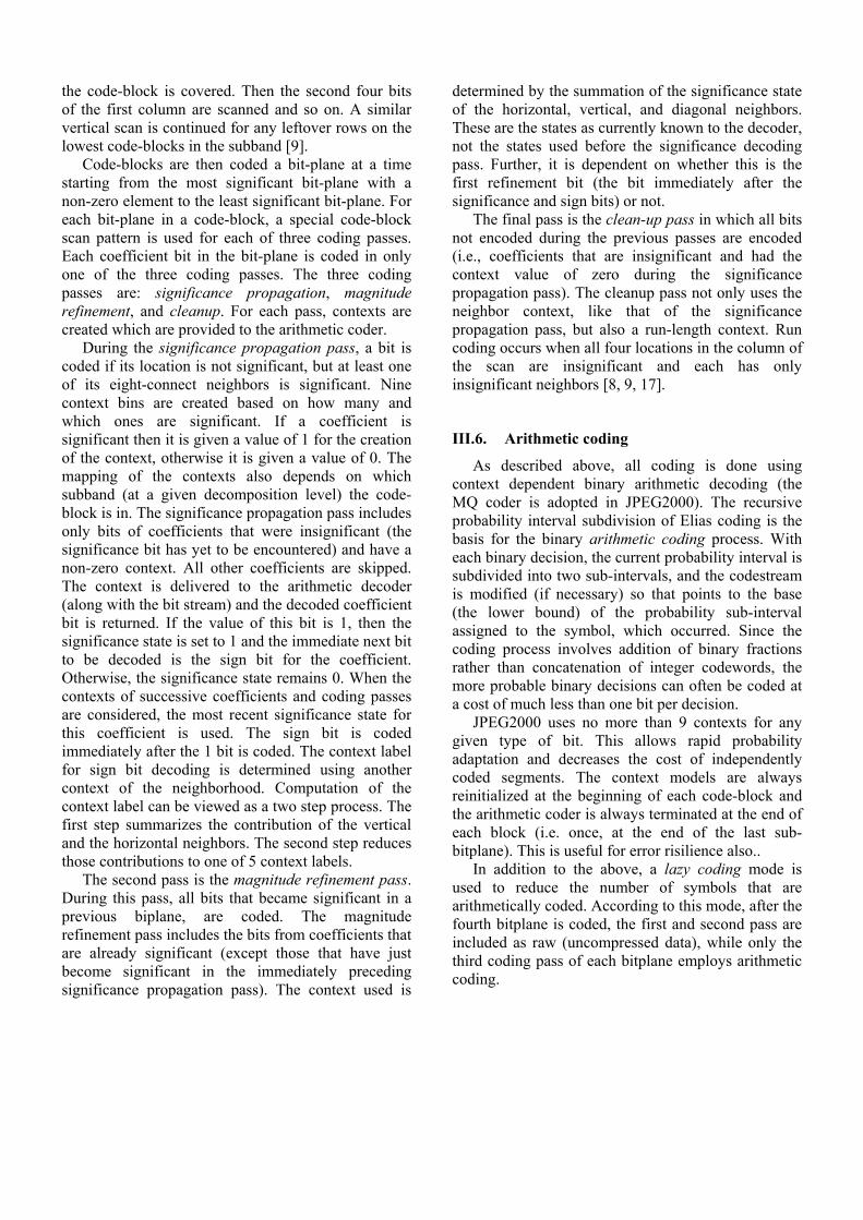
Code-blocks are then coded a bit-plane at a time starting from the most significant bit-plane with a non-zero element to the least significant bit-plane. For each bit-plane in a code-block, a special code-block scan pattern is used for each of three coding passes. Each coefficient bit in the bit-plane is coded in only one of the three coding passes. The three coding passes are: significance propagation, magnitude refinement, and cleanup. For each pass, contexts are created which are provided to the arithmetic coder.
During the significance propagation pass, a bit is coded if its location is not significant, but at least one of its eight-connect neighbors is significant. Nine context bins are created based on how many and which ones are significant. If a coefficient is significant then it is given a value of 1 for the creation of the context, otherwise it is given a value of 0. The mapping of the contexts also depends on which subband (at a given decomposition level) the code-block is in. The significance propagation pass includes only bits of coefficients that were insignificant (the significance bit has yet to be encountered) and have a non-zero context. All other coefficients are skipped. The context is delivered to the arithmetic decoder (along with the bit stream) and the decoded coefficient bit is returned. If the value of this bit is 1, then the significance state is set to 1 and the immediate next bit to be decoded is the sign bit for the coefficient. Otherwise, the significance state remains 0. When the contexts of successive coefficients and coding passes are considered, the most recent significance state for this coefficient is used. The sign bit is coded immediately after the 1 bit is coded. The context label for sign bit decoding is determined using another context of the neighborhood. Computation of the context label can be viewed as a two step process. The first step summarizes the contribution of the vertical and the horizontal neighbors. The second step reduces those contributions to one of 5 context labels.
The second pass is the magnitude refinement pass. During this pass, all bits that became significant in a previous biplane, are coded. The magnitude refinement pass includes the bits from coefficients that are already significant (except those that have just become significant in the immediately preceding significance propagation pass). The context used is
determined by the summation of the significance state of the horizontal, vertical, and diagonal neighbors. These are the states as currently known to the decoder, not the states used before the significance decoding pass. Further, it is dependent on whether this is the first refinement bit (the bit immediately after the significance and sign bits) or not.
The final pass is the clean-up pass in which all bits not encoded during the previous passes are encoded (i.e., coefficients that are insignificant and had the context value of zero during the significance propagation pass). The cleanup pass not only uses the neighbor context, like that of the significance propagation pass, but also a run-length context. Run coding occurs when all four locations in the column of the scan are insignificant and each has only insignificant neighbors [8, 9, 17].
III.6. Arithmetic coding
As described above, all coding is done using context dependent binary arithmetic decoding (the MQ coder is adopted in JPEG2000). The recursive probability interval subdivision of Elias coding is the basis for the binary arithmetic coding process. With each binary decision, the current probability interval is subdivided into two sub-intervals, and the codestream is modified (if necessary) so that points to the base (the lower bound) of the probability sub-interval assigned to the symbol, which occurred. Since the coding process involves addition of binary fractions rather than concatenation of integer codewords, the more probable binary decisions can often be coded at a cost of much less than one bit per decision.
JPEG2000 uses no more than 9 contexts for any given type of bit. This allows rapid probability adaptation and decreases the cost of independently coded segments. The context models are always reinitialized at the beginning of each code-block and the arithmetic coder is always terminated at the end of each block (i.e. once, at the end of the last sub-bitplane). This is useful for error risilience also..
In addition to the above, a lazy coding mode is used to reduce the number of symbols that are arithmetically coded. According to this mode, after the fourth bitplane is coded, the first and second pass are included as raw (uncompressed data), while only the third coding pass of each bitplane employs arithmetic coding.
III.7. Layered Bit-Stream Formation
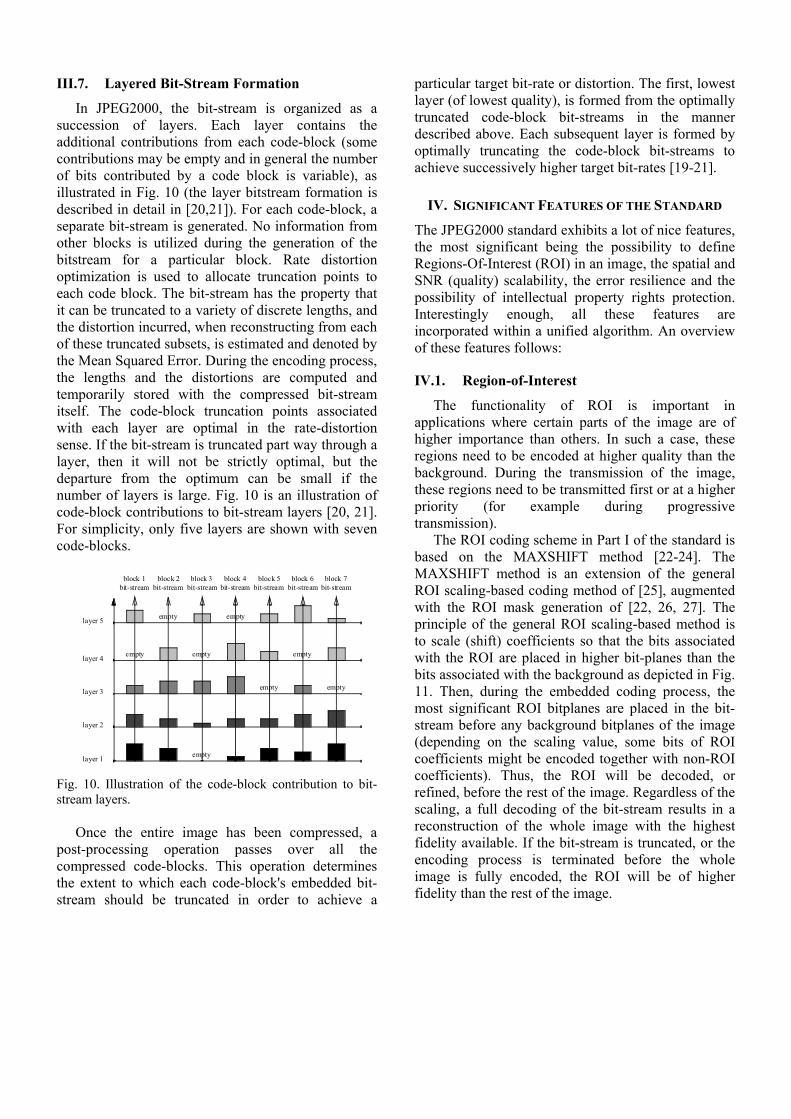
In JPEG2000, the bit-stream is organized as a succession of layers. Each layer contains the additional contributions from each code-block (some contributions may be empty and in general the number of bits contributed by a code block is variable), as illustrated in Fig. 10 (the layer bitstream formation is described in detail in [20,21]). For each code-block, a separate bit-stream is generated. No information from other blocks is utilized during the generation of the bitstream for a particular block. Rate distortion optimization is used to allocate truncation points to each code block. The bit-stream has the property that it can be truncated to a variety of discrete lengths, and the distortion incurred, when reconstructing from each of these truncated subsets, is estimated and denoted by the Mean Squared Error. During the encoding process, the lengths and the distortions are computed and temporarily stored with the compressed bit-stream itself. The code-block truncation points associated with each layer are optimal in the rate-distortion sense. If the bit-stream is truncated part way through a layer, then it will not be strictly optimal, but the departure from the optimum can be small if the number of layers is large. Fig. 10 is an illustration of code-block contributions to bit-stream layers [20, 21]. For simplicity, only five layers are shown with seven code-blocks.
Fig. 10. Illustration of the code-block contribution to bit-stream layers.
Once the entire image has been compressed, a
post-processing operation passes over all the compressed code-blocks. This operation determines the extent to which each code-block's embedded bit-stream should be truncated in order to achieve a
particular target bit-rate or distortion. The first, lowest layer (of lowest quality), is formed from the optimally truncated code-block bit-streams in the manner described above. Each subsequent layer is formed by optimally truncating the code-block bit-streams to achieve successively higher target bit-rates [19-21].
IV. SIGNIFICANT FEATURES OF THE STANDARD
The JPEG2000 standard exhibits a lot of nice features, the most significant being the possibility to define Regions-Of-Interest (ROI) in an image, the spatial and SNR (quality) scalability, the error resilience and the possibility of intellectual property rights protection. Interestingly enough, all these features are incorporated within a unified algorithm. An overview of these features follows:
IV.1. Region-of-Interest
The functionality of ROI is important in applications where certain parts of the image are of higher importance than others. In such a case, these regions need to be encoded at higher quality than the background. During the transmission of the image, these regions need to be transmitted first or at a higher priority (for example during progressive transmission).
The ROI coding scheme in Part I of the standard is based on the MAXSHIFT method [22-24]. The MAXSHIFT method is an extension of the general ROI scaling-based coding method of [25], augmented with the ROI mask generation of [22, 26, 27]. The principle of the general ROI scaling-based method is to scale (shift) coefficients so that the bits associated with the ROI are placed in higher bit-planes than the bits associated with the background as depicted in Fig. 11. Then, during the embedded coding process, the most significant ROI bitplanes are placed in the bit-stream before any background bitplanes of the image (depending on the scaling value, some bits of ROI coefficients might be encoded together with non-ROI coefficients). Thus, the ROI will be decoded, or refined, before the rest of the image. Regardless of the scaling, a full decoding of the bit-stream results in a reconstruction of the whole image with the highest fidelity available. If the bit-stream is truncated, or the encoding process is terminated before the whole image is fully encoded, the ROI will be of higher fidelity than the rest of the image.
empty empty
empty empty empty
empty empty
empty
block 1bit-stream
block 2bit-stream
block 3bit-stream
block 4bit-stream
block 5bit-stream
block 6bit-stream
block 7bit-stream
layer 5
layer 4
layer 3
layer 2
layer 1
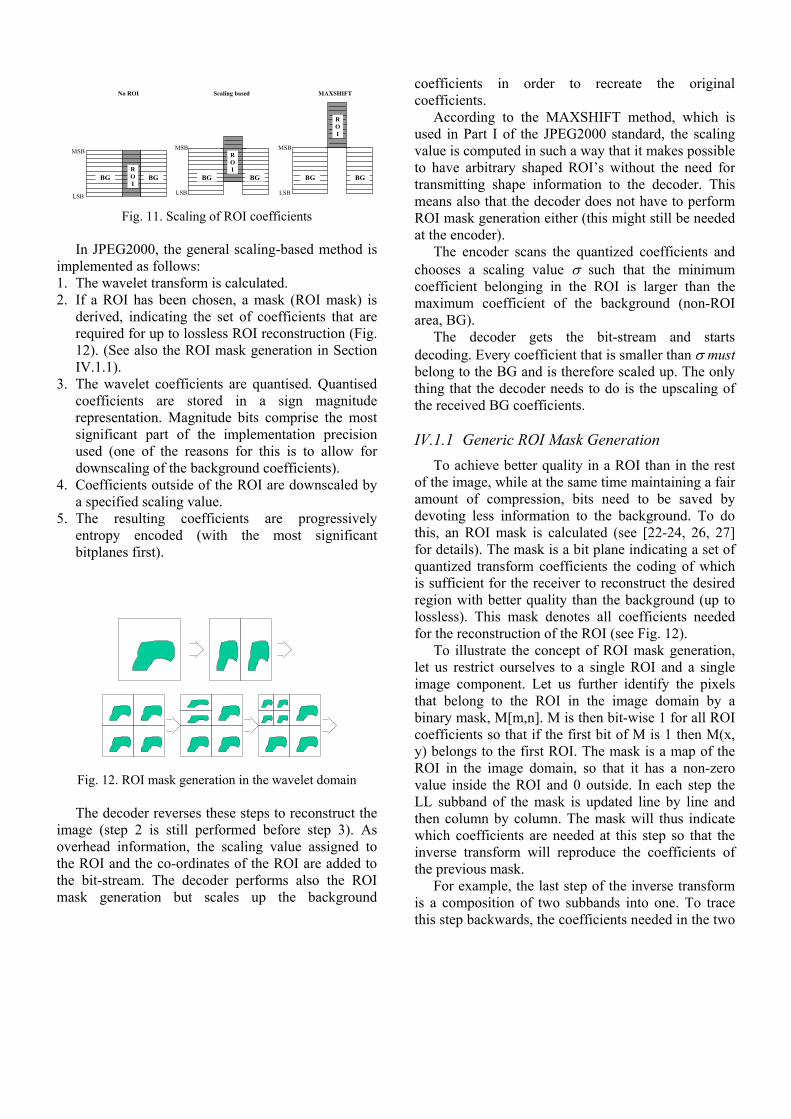
Fig. 11. Scaling of ROI coefficients In JPEG2000, the general scaling-based method is
implemented as follows: 1. The wavelet transform is calculated. 2. If a ROI has been chosen, a mask (ROI mask) is
derived, indicating the set of coefficients that are required for up to lossless ROI reconstruction (Fig. 12). (See also the ROI mask generation in Section IV.1.1).
3. The wavelet coefficients are quantised. Quantised coefficients are stored in a sign magnitude representation. Magnitude bits comprise the most significant part of the implementation precision used (one of the reasons for this is to allow for downscaling of the background coefficients).
4. Coefficients outside of the ROI are downscaled by a specified scaling value.
5. The resulting coefficients are progressively entropy encoded (with the most significant bitplanes first).
Fig. 12. ROI mask generation in the wavelet domain The decoder reverses these steps to reconstruct the
image (step 2 is still performed before step 3). As overhead information, the scaling value assigned to the ROI and the co-ordinates of the ROI are added to the bit-stream. The decoder performs also the ROI mask generation but scales up the background
coefficients in order to recreate the original coefficients.
According to the MAXSHIFT method, which is used in Part I of the JPEG2000 standard, the scaling value is computed in such a way that it makes possible to have arbitrary shaped ROI’s without the need for transmitting shape information to the decoder. This means also that the decoder does not have to perform ROI mask generation either (this might still be needed at the encoder).
The encoder scans the quantized coefficients and chooses a scaling value σ such that the minimum coefficient belonging in the ROI is larger than the maximum coefficient of the background (non-ROI area, BG).
The decoder gets the bit-stream and starts decoding. Every coefficient that is smaller than σ must belong to the BG and is therefore scaled up. The only thing that the decoder needs to do is the upscaling of the received BG coefficients.
IV.1.1 Generic ROI Mask Generation
To achieve better quality in a ROI than in the rest of the image, while at the same time maintaining a fair amount of compression, bits need to be saved by devoting less information to the background. To do this, an ROI mask is calculated (see [22-24, 26, 27] for details). The mask is a bit plane indicating a set of quantized transform coefficients the coding of which is sufficient for the receiver to reconstruct the desired region with better quality than the background (up to lossless). This mask denotes all coefficients needed for the reconstruction of the ROI (see Fig. 12).
To illustrate the concept of ROI mask generation, let us restrict ourselves to a single ROI and a single image component. Let us further identify the pixels that belong to the ROI in the image domain by a binary mask, M[m,n]. M is then bit-wise 1 for all ROI coefficients so that if the first bit of M is 1 then M(x, y) belongs to the first ROI. The mask is a map of the ROI in the image domain, so that it has a non-zero value inside the ROI and 0 outside. In each step the LL subband of the mask is updated line by line and then column by column. The mask will thus indicate which coefficients are needed at this step so that the inverse transform will reproduce the coefficients of the previous mask.
For example, the last step of the inverse transform is a composition of two subbands into one. To trace this step backwards, the coefficients needed in the two
LSB
MSB
LSB
MSB
LSB
MSB
BGBGBGBGBG BGROI
ROI
ROI
No ROI Scaling based MAXSHIFT
subbands, are found. The previous step is a composition of four subbands into two. To trace this step backwards, the coefficients in the four subbands, needed to give a perfect reconstruction, are found. All steps are then traced backwards to give the mask. If the coefficients corresponding to the mask are transmitted and received, and the inverse transform is calculated on them, the desired ROI will be reconstructed with better quality than the rest of the image. (Up to lossless could be achieved, if the ROI coefficients were coded losslessly).
To find the coefficients that need to be in the mask,
the inverse wavelet transformation is studied. For the 5/3 filter it can be seen that to reconstruct X(2n) and X(2n+1) losslessly, coefficients L(n), L(n+1), H(n-1), H(n), H(n+1) are needed (Fig.13). Hence if X(2n) or X(2n+1) are in the ROI, the listed low and high sub-
band coefficients are in the mask.
n-1 n n+1Low High
n-1 n n+1
X:s
2n 2n+1
Fig. 13. The inverse 5/3 filter
IV.1.2. ROI Coding Performance Comparisons The advantages of the MAXSHIFT method
compared to the “scaling based method” is that encoding of arbitrary shaped ROI’s is now possible without the need for shape information at the decoder (i.e. no shape decoder is required) and without the need for calculating the ROI mask at the decoder. The
encoder is also simpler, since no shape encoding is required. The decoder is almost as simple as a non-ROI capable decoder, while it can still handle ROI’s of arbitrary shape.
Woman - 25% ROI - Relative size
0,997
0,998
0,999
1
1,001
1,002
1,003
1,004
1,005
No ROIS=2S=4Max Shift
Target - approx. 25% circular ROI - Relative sizes
0,94
0,96
0,98
1
1,02
1,04
1,06
1,08
1,1
No ROIS=2S=4Max shift
Aerial2 - approx. 25% circular ROI - Relative sizes
0,994
0,996
0,998
1
1,002
1,004
1,006
1,008
1,01
1,012
No ROIS=2S=4Max shift
Gold - 25% Rect ROI - Relative sizes
0,98
0,99
1
1,01
1,02
1,03
1,04
No ROIS=2S=4Max shift
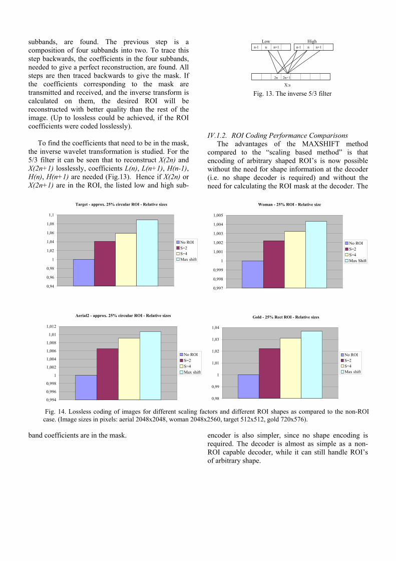
Fig. 14. Lossless coding of images for different scaling factors and different ROI shapes as compared to the non-ROI case. (Image sizes in pixels: aerial 2048x2048, woman 2048x2560, target 512x512, gold 720x576).
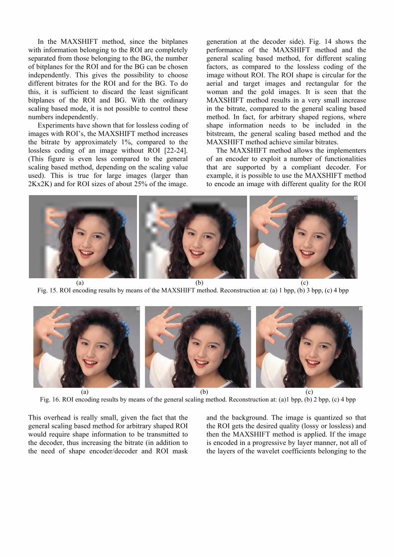
In the MAXSHIFT method, since the bitplanes with information belonging to the ROI are completely separated from those belonging to the BG, the number of bitplanes for the ROI and for the BG can be chosen independently. This gives the possibility to choose different bitrates for the ROI and for the BG. To do this, it is sufficient to discard the least significant bitplanes of the ROI and BG. With the ordinary scaling based mode, it is not possible to control these numbers independently.
Experiments have shown that for lossless coding of images with ROI’s, the MAXSHIFT method increases the bitrate by approximately 1%, compared to the lossless coding of an image without ROI [22-24]. (This figure is even less compared to the general scaling based method, depending on the scaling value used). This is true for large images (larger than 2Kx2K) and for ROI sizes of about 25% of the image.
This overhead is really small, given the fact that the general scaling based method for arbitrary shaped ROI would require shape information to be transmitted to the decoder, thus increasing the bitrate (in addition to the need of shape encoder/decoder and ROI mask
generation at the decoder side). Fig. 14 shows the performance of the MAXSHIFT method and the general scaling based method, for different scaling factors, as compared to the lossless coding of the image without ROI. The ROI shape is circular for the aerial and target images and rectangular for the woman and the gold images. It is seen that the MAXSHIFT method results in a very small increase in the bitrate, compared to the general scaling based method. In fact, for arbitrary shaped regions, where shape information needs to be included in the bitstream, the general scaling based method and the MAXSHIFT method achieve similar bitrates.
The MAXSHIFT method allows the implementers of an encoder to exploit a number of functionalities that are supported by a compliant decoder. For example, it is possible to use the MAXSHIFT method to encode an image with different quality for the ROI
and the background. The image is quantized so that the ROI gets the desired quality (lossy or lossless) and then the MAXSHIFT method is applied. If the image is encoded in a progressive by layer manner, not all of the layers of the wavelet coefficients belonging to the
(a) (b) (c) Fig. 15. ROI encoding results by means of the MAXSHIFT method. Reconstruction at: (a) 1 bpp, (b) 3 bpp, (c) 4 bpp
(a) (b) (c) Fig. 16. ROI encoding results by means of the general scaling method. Reconstruction at: (a)1 bpp, (b) 2 bpp, (c) 4 bpp

background need be encoded. This corresponds to using different quantization steps for the ROI and the background. Fig. 15 shows an example of ROI coding with the MAXSHIFT method. Notice that the ROI is used in all subbands. This is the reason why at the early stages of the transmission, not enough information is used for the background. For comparison purposes, the same result is shown in Fig. 16 for the general scaling based method, with the scaling value set to 6. Similar results can be obtained with the MAXSHIFT method if the few low-resolution subbands are considered as full ROI’s. The results show that the MAXSHIFT method can give similar results to the general scaling method, without the need of shape information and mask generation at the decoder.
IV.1.3 A note on ROI coding
Evidently, ROI coding is a process done at the encoder. The encoder decides which is the ROI that to be coded in better quality than the background. If the ROI’s are not known before the encoding process, there are still possibilities for a decoder to receive only the data that is requesting (a method for interactive ROI selection is described in [28]). Although the simplest method is tiling, this still requires that the image is encoded in tiling mode. Another way is to extract packet partitions from the bitstream. This can be done easily, since the length information is stored in the header. Due to the filter impulse response lengths, care has to be taken to extract all data required to decode the ROI [17]. Finer grain access can be achieved by parsing individual code blocks. As in the case of packet partition
location, it is necessary to determine which code-blocks affect which pixel locations (since a single pixel can affect four different code blocks within each subband and each resolution and each component). We can determine the correct packet affecting these code blocks from the progression order information. And the location of the compressed data for the code-blocks can be determined by decoding the packet headers. This might be easier than operating the arithmetic coder and context modeling to decode the data [17].
The procedure of coefficient scaling might in some cases cause overflow problems, due to the limited implementation precision. In JPEG2000 this problem is minimized since the BG coefficients are scaled down, rather than scaling up the ROI coefficients. Thus, if the implementation precision is exceeded only the least significant bit planes of the BG will be lost (the decoder or the encoder will ignore this part). The advantage is that the ROI, which is considered to be the most important part of the image, is still optimally treated, while the quality of the background is allowed to have degraded quality (it is considered to be less important).
The ROI general scaling method can be applied basically to any embedded coding scheme. As an example, the method has been applied in embedded DCT based coders [29, 30], in different wavelet filters [31] and in zerotree coders [32-34].
IV.2. Scalability and bitstream parsing
(a) (b) (c) Fig. 17. Example of SNR scalability. Decompressed image at (a) 0.125 bpp, (b) 0.25 bpp and (c) 0.5 bpp

Realizing that many applications require images to be simultaneously available for decoding at a variety of resolutions or qualities, the JPEG2000 compression system supports scalability. In general, scalable coding of still images means the ability to achieve coding of more than one resolution and/or quality simultaneously. Scalable image coding involves generating a coded representation (bitstream) in a manner which facilitates the derivation of images of more than one resolution and/or quality by scalable decoding. Bitstream scalability is the property of a bitstream that allows decoding of appropriate subsets of a bitstream to generate complete pictures of resolution and/or quality commensurate with the proportion of the bitstream decoded. If a bitstream is truly scalable, decoders of different complexities (from low performance to high performance) can coexist. While low performance decoders may decode only small portions of the bitstream producing basic quality, high performance decoders may decode much more and produce significantly higher quality. The most important types of scalability are SNR scalability and spatial scalability. A remarkable advantage of scalability is its ability to provide resilience to transmission errors, as the most important data of the lower layer can be sent over the channel with better error performance, while the less critical enhancement layer data can be sent over the channel with poor error performance. Both types of scalability
are very important for Internet and database access applications, and bandwidth scaling for robust delivery. The SNR and spatial scalability types include the progressive and hierarchical coding modes defined in the current JPEG, but they are more general.
IV.2.1. SNR scalability
SNR scalability is intended for use in systems with the primary common feature that a minimum of two layers of image quality is necessary. SNR scalability involves generating at least two image layers of the same spatial resolution, but different qualities, from a single image source. The lower layer is coded by itself to provide the basic image quality and the enhancement layers are coded to enhance the lower layer. An enhancement layer, when added back to the lower layer, regenerates a higher quality reproduction of the input image. Fig. 17 shows an example of SNR scalability. The image is compressed in SNR scalable manner at 0.5 bpp and is decompressed at 0.125 bpp, 0.25 bpp and 0.5 bpp.
IV.2.2. Spatial scalability
Spatial scalability is intended for use in systems with the primary common feature that a minimum of two layers of spatial resolution is necessary. Spatial scalability involves generating at least two spatial resolution layers from a single source such that the lower layer is coded by itself to provide the basic
Fig. 18. Example of the progressive by resolution coding for the color image “woman”

spatial resolution and the enhancement layer employs the spatially interpolated lower layer and carries the full spatial resolution of the input image source. Fig. 18 shows an example of 3 levels of progressive-by-resolution coding for the image “woman”. Spatial scalability is useful for fast database access as well as for delivering different resolutions to terminals with different capabilities in terms of display and bandwidth capabilities. IV.2.3. Bitstream parsing
JPEG2000 supports a combination of spatial and SNR scalability. It is possible therefore to progress by spatial scalability at a given (resolution) level and then change the progression by SNR at a higher level. This order in progression allows a thumbnail to be displayed first, then a screen resolution image and then an image suitable for the resolution of the printer. It is evident that SNR scalability at each resolution allows the best possible image to be displayed at each resolution.
Notice that the bitstream contains markers that identify the progression type of the bitstream. The data stored in packets are identical regardless of the type of scalability used. Therefore it is trivial to change the progression type or to extract any required data from the bitstream. To change the progression from SNR to progressive by resolution, a parser can read the markers, change the type of progression in the markers and then write the new markers in the new order. In this manner, fast transcoding of the bitstream can be achieved in a server or gateway, without requiring the use of image decoding and re-encoding, not even the run of MQ-coder, context modeling. The complexity corresponds to that of a copy operation [17].
Similarly, applications that require the use of a gray scale version of a color compressed image, as for example printing a color image to a gray-scale printer, do not need to receive all color components. A parser can read the markers from the color components and write the markers for one of the components (discarding the packets that contain the color information) [17].
IV.3. Line Based Transforms
Traditional wavelet transform implementations require the whole image to be buffered and the filtering operation to be performed in vertical and
horizontal directions. While filtering in the horizontal direction is very simple, filtering in the vertical direction is more cumbersome. Filtering along a row requires one row to be read; filtering along a column requires the whole image to be read. The line-based wavelet transform overcomes this difficulty, providing exactly the same transform coefficients as the traditional wavelet transform implementation (see [9, 35, 36]). However, the line-based wavelet transform alone does not provide a complete line-based encoding paradigm for JPEG2000. A complete row-based coder has to take also into account all the subsequent coding stages up to the entropy coding one. Such an algorithm is described in [35, 36].
IV.4. Visual Frequency Weighting
The human visual system plays an important role in the perceived image quality of compressed images [37, 38]. System designers and users should be able to take advantage of the current knowledge of visual perception, i.e. to utilize models of the visual system’s varying sensitivity to spatial frequencies, as measured in the contrast sensitivity function (CSF). Since the CSF weight is determined by the visual frequency of the transform coefficient, there will be one CSF weight per subband in the wavelet transform. The design of the CSF weights is an encoder issue and depends on the specific viewing condition under which the decoded image is to be viewed.
Two types of visual frequency weighting are supported by the JPEG2000. The Fixed Visual Weighting (FVW) and the Visual Progressive Coding (VPC). In FVW, only one set of CSF weights is chosen and applied in accordance with the viewing conditions. In VPC, different weights are used at the various stages of the embedded coding. This is because during a progressive transmission stage, the image is viewed at various distances. For example, at low rates, the image is viewed from a relatively large distance, while as more and more bits are received and the quality is improved, the viewing distance is decreased (the user is more interested in details and the viewing distance is decreased or the image is magnified, which is equivalent to reducing the viewing distance). It can be considered that FVW is a special case of VPC.
IV.5. Error Resilience
JPEG2000 uses a variable length coder (arithmetic coder) to compress the quantized wavelet coefficients.

Variable length coding is known to be prone to channel or transmission error. A bit error results in loss of synchronization at the entropy decoder and the reconstructed image can be severely damaged. To improve the performance of transmitting compressed images over error prone channels, error resilient bit stream syntax and tools are included in the standard. The error resilience tools deal with channel errors using the following approaches: data partitioning and resynchronization, error detection and concealment, and Quality of Service (QoS) transmission based on priority [9, 39-40]. Error resilience is achieved at the entropy coding level and at the packet level. Table IV summarizes the various ways this is achieved [9].
TABLE IV
Tools for error resilience Type of tool Name
Entropy coding level
• code-blocks
• termination of the arithmetic coder for each pass
• reset of contexts after each coding pass
• selective arithmetic coding bypass
• segmentation symbols
Packet level
• short packet format
• packet with resynchronization marker
Entropy coding of the quantized coefficients is
performed within code-blocks. Since encoding and decoding of the code-blocks are independent processes, bit errors in the bit stream of a code-block will be restricted within that code-block. To increase error resilience, termination of the arithmetic coder is allowed after every coding pass and the contexts may be reset after each coding pass. This allows the arithmetic decoder to continue the decoding process even if an error has occurred.
The “lazy coding” mode (see Section III.6) is also useful for error resilience. This relates to the optional arithmetic coding bypass, in which bits are used as raw bits into the bit stream without arithmetic coding. This prevents the error propagation types to which variable length coding is susceptible.
At the packet level, a packet with a resynchronization marker allows spatial partitioning and resynchronization. This is placed in front of every packet in a tile with a sequence number starting at zero and incremented with each packet.
IV.6. New File Format with IPR Capabilities
An optional file format for the JPEG2000 compressed image data is defined in the standard. The JPEG 2000 file format (JP2 format) provides a foundation for storing application specific data (metadata) in association with a JPEG 2000 codestream, such as information required to display the image. This format has got provisions for both image and metadata and specifies mechanisms to indicate image properties, such as the tonescale or colorspace of the image, to recognize the existence of intellectual property rights (IPR) information in the file and to include metadata (as for example vendor specific information). Metadata give the opportunity to the reader to extract information about the image, without having to decode it, thus allowing fast text based search in a database.
In addition to specifying the colorspace, the standard allows for the decoding of single component images, where the value of that single component represents an index into a palette of colors. Input of a decompressed sample to the palette converts the single value to a multiple-component tuple. The value of that tuple represents the color of the sample.
In summary, the file format contains the size of the image, the bit depth of the components in the file in cases where the bit depth is not constant across all components, the colorspace of the image, the palette which maps a single component in index space to a multiple-component image, the type and ordering of the components within the codestream, the resolution of the image, the resolution at which the image was captured, the default resolution at which the image should be displayed, the codestream, intellectual property information about the image, a tool by which vendors can add XML formatted information to a JP2 file, etc [8, 9].
V. COMPARATIVE RESULTS
In this section the efficiency of the algorithm in comparison with existing lossless and lossy
compression standards is studied. More detailed results can be found in [42,47].
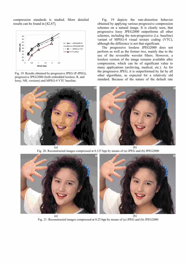
Fig. 19 depicts the rate-distortion behavior obtained by applying various progressive compression schemes on a natural image. It is clearly seen, that progressive lossy JPEG2000 outperforms all other schemes, including the non-progressive (i.e. baseline) variant of MPEG-4 visual texture coding (VTC), although the difference is not that significant.
The progressive lossless JPEG2000 does not perform as well as the former two, mainly due to the use of the reversible wavelet filters. However, a lossless version of the image remains available after compression, which can be of significant value to many applications (archiving, medical, etc.). As for the progressive JPEG, it is outperformed by far by all other algorithms, as expected for a relatively old standard. Because of the nature of the default rate
(a) (b) Fig. 20. Reconstructed images compressed at 0.125 bpp by means of (a) JPEG and (b) JPEG2000
30
32
34
36
38
40
42
44
46
0 0,5 1 1,5 2 2,5
Bitrate (bpp)
PSN
R (d
B) JPEG2000 R
JPEG2000 NR
MPEG-4 VTC
P-JPEG
Fig. 19. Results obtained by progressive JPEG (P-JPEG), progressive JPEG2000 (both embedded lossless, R, and lossy, NR, versions) and MPEG-4 VTC baseline.
(a) (b) Fig. 21. Reconstructed images compressed at 0.25 bpp by means of (a) JPEG and (b) JPEG2000

allocation algorithm in the JPEG2000 software the non-progressive variants of JPEG2000 would be practically identical to the progressive ones, hence the omission of those in the figure.
The JPEG software used is the one provided by the Independent JPEG Group (http://www.ijg.org) and the JPEG-LS software from the University of British Columbia (http://spmg.ece.ubc.ca) version 2.2. The Lossless JPEG version 1.0 of Cornell University was also used (ftp://ftp.cs.cornell.edu/pub/multimed). The MPEG-4 VTC is also included in the comparisons [43].
The superiority of the JPEG2000 can be subjectively judged with the help of Fig. 20, where part of the reconstructed image ‘woman’ is shown after compression at 0.125 bpp. Fig. 21 shows the result after compression at 0.25 bpp. Results of a compound image compressed with JPEG baseline and JPEG2000 at 1 bpp are shown in Fig. 22. It is again evident that JPEG2000 outperforms JPEG baseline.
This performance superiority of the JPEG2000 decreases as the bitrate increases. In fact, from the compression point of view, JPEG2000 will give about 10-20% better compression factors compared to JPEG baseline, for a bitrate of about 1 bpp. Visual comparisons of JPEG compressed images (baseline JPEG with optimized Huffman tables) and JPEG2000 compressed images showed that for a large category of images, JPEG2000 file sizes were on average 11% smaller than JPEG at 1.0 bpp, 18% smaller at 0.75 bpp, 36% smaller at 0.5 bpp and 53% smaller at 0.25 bpp [41]. In general, we can say that for high quality imaging applications (i.e. 0.5-1.0 bpp) JPEG2000 is 10-20% better than JPEG.
TABLE V PSNR results in dB for 200 runs of the decoded ‘cafe’ image
transmitted over a noisy channel for various bit error rates (ber) and compression rates for the JPEG baseline and the JPEG2000
bpp
↓
ber → 0 1e-6 1e-5 1e-4
JPEG2000 23.06 23.00 21.62 16.59 0.25
JPEG 21.94 21.79 20.77 16.43
JPEG2000 26.71 26.42 23.96 17.09 0.5
JPEG 25.40 25.12 22.95 15.73
JPEG2000 31.90 30.75 27.08 16.92 1.0
JPEG 30.84 29.24 23.65 14.80
JPEG2000 38.91 36.38 27.23 17.33 2.0
JPEG 37.22 30.68 20.78 12.09
TABLE VI
Bitrates for the lossless compression of ‘Lena’ and ‘cmpnd1’ images. (In parentheses the compression ratio is given).
Image lossless JPEG
JPEG-LS
JPEG2000
Lena (512x512,
24bpp)
14.75
(1.627:1)
13.56
(1.770:1)
13.54
(1.773:1) Cmpnd1
(512x768, 8bpp)
2.48
(3.226:1)
1.24
(6.452:1)
2.12
(3.774:1) Error resilience of JPEG2000 has been evaluated
in [42, 47]. A transmission channel with random errors has been simulated and the average (a) (b)
Fig. 22. Reconstructed images compressed at 1 bpp by means of (a) JPEG and (b) JPEG2000. (The images shown are parts of a compound test image of JPEG2000).
PS NR [dB] - Filter Com parison (Ho tel)
0
5
10
15
20
25
30
35
40
45
50
0,0625 bpp 0,125 bpp 0,25 bpp 0,5 bpp 1,0 bpp 2,0 bpp
Deco ded bit rate [bpp ]
PSN
R [d
B] W 9X7(Float)W 13X7CRF (Int)W 5X3(Int)W 10X18(Float)
Fig. 23. Compression efficiency results of different filters.

reconstructed image quality after decompression has been neasured (Table V). In the case of JPEG, the results were obtained by using the maximum amount
of restart markers, which amounts to an overhead of less than 1%. In the case of JPEG2000, the sensitive packet information was moved to the bitstream header (using the PPM marker [9]) and the entropy coded data had been protected by the regular termination of the arithmetic coder combined with the error resilience termination and segment symbols (the overhead for these protections is less than 1%). In both cases the bitstream header was transmitted without errors. As can be deduced from Table V, the reconstructed image quality under transmission errors is higher for JPEG2000 compared to that of JPEG. However, at low rates (0.25 and 0.5 bpp), the quality of JPEG2000 decreases more rapidly than JPEG as the error rate increases. An interesting observation is that at higher error rates (i.e. 1e-4), the reconstructed image quality in JPEG2000 is almost constant across all bitrates.
This is due to the fact that in JPEG2000 each subband block is coded by bitplanes. When the error rate is high enough almost all blocks are affected in
the most significant bit-planes, which are transmitted first. When a particular bitplane is affected in a block, lower bitplanes can not be decoded and are therefore useless. In the case of JPEG the problem is even worse: the higher the encoding bitrate the lower the decoded quality. This can be explained by the fact that when an 8x8 block is affected by a transmission error the entire block is basically lost. The higher the encoding bitrate, the more bits it takes to code a block, and therefore the probability of a block being hit by an error and lost is higher for the same bit error rate. In other words, in JPEG the density of error protection decreases with an increase in bitrate.
Results with different filters are shown in Fig. 23 for the test image ‘hotel’ of JPEG2000. The integer filters 13/7 and 10/18 are also included for comparison purposes. Evidently, the results are very close. For computational complexity issues, the 9/7 filter is included in Part I of JPEG2000 standard and the 5/3 for lossless coding. A comparison of various filters for lossless coding is shown in Fig. 24 for the 2/10, 13/7 and 5/3 integer filters. Since all of them give almost identical results, the 5/3 is included in Part I of JPEG2000 for lossless coding applications.
The lossless compression efficiency of JPEG2000 versus the lossless mode of JPEG [1, 3] and JPEG-LS [46] for a natural and a compound image are reported in Table VI. It is seen that JPEG2000 performs equivalently to JPEG-LS in the case of the natural image, with the added benefit of scalability. JPEG-LS, however, is advantageous in the case of the compound image. Taking into account that JPEG-LS is significantly less complex than JPEG2000, it is reasonable to use JPEG-LS for lossless compression. In such a case though, the generality of JPEG2000 is
Image: Gold
237500
238000
238500
239000
239500
240000
File
siz
e in
byt
es
W5X3W2X10W13X7
Fig. 24. Lossless coding efficiency of different integer filters.
TABLE VII Evaluation of the functionalities of the compression algorithms. (A plus sign indicates that the functionality is supported.
The more plus signs the greater the efficiency. A minus sign indicates that the corresponding functionality is not supported. The JPEG row refers to all modes of the standard. The parenthesis indicate that a separate mode is required.)
Algorithm Lossless comp.
Lossy comp.
Embedded bitstream
Region of
interest
Arbitrary shaped object
Error resilient
Scalable Complexity
Random access
Generic
JPEG (+) ++ - - - - (+) ++(+) + + MPEG-4 VTC - +++ +++ + ++ ++ ++ + - ++
JPEG-LS ++++ + + - - - - ++ - + JPEG2000 +++ +++ +++ ++ - ++ ++ +++ ++ +++

sacrificed. More results can be found in [43]. Comparative results of JPEG, JPEG-LS and JPEG2000 from the functionality point of view are reported in Table VII. The Verification Model 6.1 of JPEG2000 (ISO/IEC JTC1/SC29/WG1 N1580) has been used in this case. A plus (minus) sign indicates that the corresponding functionality is supported (not supported). The more the plus signs the greater the support. The parentheses indicate that a separate mode is required. As it can be deduced from Table VII the JPEG2000 standard offers the richest set of features in a very efficient way and within a unified algorithm [42, 46, 47].
MPEG-4 VTC and JPEG2000 produce progressive bitstreams. JPEG2000 provides bitstreams that are parseable and can easily be reorganized by a transcoder on the fly. JPEG2000 also allows random access (with minimal decoding) to the block-level of each subband, thus making possible to decode a region of an image without decoding the whole image. Notice that MPEG-4 supports coding of arbitrary shape objects by means of an adaptive DWT, but it does not support lossless coding.
Notice that DCT based algorithms can also achieve many of the features of JPEG2000, as ROI, embedded bitstream, etc [29, 30, 48]. However, DCT based coding schemes, due to the block-based coding nature, cannot perform well at low rates, unless postprocessing operations are involved [3]. The complexity of those schemes is increased compared to baseline JPEG and their compression performance is not better than wavelet based coding schemes (although very close). Additionally, although JPEG2000 offers better performance than JPEG, different types of artifacts appear in wavelet based coders. Some results on postprocessing of JPEG2000 compressed images for tiling and ringing artifact reduction, have already been reported [49,50].
VI. FUTURE PARTS OF THE STANDARD
The future parts of the standard are Part II, throughout Part VII. Part I describes the core coding system, which should be used to provide maximum interchange. Part II (Extensions) consists of optional technologies not required for all implementations. Evidently, images encoded with Part II technology will not be able to be decoded with Part I decoders. As an example, Part II will include Trellis Coded Quantization [51,52], possibly user defined wavelets,
packet and other decompositions, general scaling-based ROI coding method, mixed fixed length coding and variable length coding, advanced error resilience schemes, etc. Part III will define motion JPEG2000 (MJP2) and will be based on Part I of JPEG2000. MJP2 will be used in many different areas: in applications where it is desired to have a single codec for both still pictures and motion sequences (which is a common feature of digital still cameras), also for very high quality motion pictures –medical imaging (it will allow both lossy and lossless compression in a single codec) and motion picture production- and for video in error prone environments, such as wireless and the Internet. The Standard will allow one or more JPEG2000 compressed image sequences, synchronized audio and metadata to be stored in the Motion JPEG 2000 file format (MJ2). Finally, Motion JPEG2000 is targeting interoperability with the JPEG2000 file format (JP2) and the MPEG-4 file format (MP4).
Part IV of the standard will define the conformance testing. Part V will define the reference software as high quality free software. Currently, two reference software implementations do exist: The JJ2000 software (developed by Canon Research France, EPFL and Ericsson), that is a JavaTM implementation of the JPEG2000 (available at http://jj2000.epfl.ch). The JasPer software is a C implementation by Image Power and the University of British Columbia (available at http://www.ece.ubc.ca/ mdadams/jasper/). Part VI will define a compound image file format, while Part VII will result in a technical report with guidelines of minimum support function of Part I. The workplan of these parts is also shown in Table VIII.
TABLE VIII Schedule for upcoming standards of JPEG2000
Part CD FCD FDIS IS
II (Extensions) 08/2000 12/2000 04/2001 07/2001
III (Motion JPEG2000)
12/2000 03/2001 08/2001 11/2001
IV (Conformance Testing)
12/2000 03/2001 08/2001 11/2001
V (Reference Software)
07/2000 12/2000 04/2001 07/2001
VI (Compund Image File Format)
08/2000 12/2000 04/2001 07/2001
VII (Technical Report: Guideline of
(PDTR)
12/2000
(DTR)
3/2001
(TR)
07/2001

minimum support function of Part-1)
VII. CONCLUSIONS
JPEG2000 is the new standard for still image compression that is going to be in use by the beginning of next year. It provides a new framework and an integrated toolbox to better address increasing needs for compression. It also provides a wide range of functionalities for still image applications, like Internet, color facsimile, printing, scanning, digital photography, remote sensing, mobile applications, medical imagery, digital library and E-commerce. Lossless and lossy coding, embedded lossy to lossless, progressive by resolution and quality, high compression efficiency, error resilience and lossless color transformations are some of its characteristics. Comparative results have shown that JPEG2000 is indeed superior to existing still image compression standards. Work is still needed in optimizing its implementation performance.
ACKNOWLEDGEMENTS
The authors would like to thank Diego Santa Cruz from EPFL, Mathias Larsson, Joel Askelof, Niklas Björk, Daniel Berg from Ericsson, Sweden and Eugenia Christopoulou from the Univeristy of Patras for their contribution in the simulations and their valuable comments.
REFERENCES
[1] G. K. Wallace, “The JPEG Still Picture Compression
Standard”, IEEE Trans. Consumer Electronics, Vol. 38, No 1, Feb. 1992.
[2] W. B. Pennebaker and J. L. Mitcell, “JPEG: Still Image Data Compression Stndard”, Van Nostrand Reinhold, 1993.
[3] V. Bhaskaran and K. Konstantinides, “Image and Video Compression Standards: Algorithms and Applications”, 2nd Ed., Kluwer Academic Publishers, 1997.
[4] ISO/IEC JTC1/SC29/WG1 N505, “Call for contributions for JPEG 2000 (JTC 1.29.14, 15444): Image Coding System,” March 1997.
[5] ISO/IEC JTC1/SC29/WG1 N390R, “New work item: JPEG 2000 image coding system,” March 1997.
[6] ISO/IEC JTC1/SC29/WG11 N3464, “MPEG-7 Multimedia Description Schemes XM (version 4.0),” August 2000.
[7] ISO/IEC JTC1/SC29/WG1 N1359, “Information Technology – Coded Representation of Picture and Audio Information – Lossy/Lossless Coding of Bi-level Images”, 14492 Final Committee Draft, July 1999.
[8] C. Christopoulos (editor), “JPEG2000 Verification Model 8.0 (technical description),” ISO/IEC JTC1/SC29/WG1 N1822, July 21, 2000.
[9] M. Boliek, C. Christopoulos and E. Majani (editors), “JPEG2000 Part I Final Draft International Standard,” (ISO/IEC FDIS15444-1), ISO/IEC JTC1/SC29/ WG1 N1855, August 18, 2000.
[10] M. Antonini, M. Barlaud, P. Mathieu and I. Daubechies: “Image Coding Using the Wavelet Transform”, IEEE Trans. Image Proc., pp. 205-220, April 1992.
[11] D. Le Gall and A. Tabatabai, “Subband Coding of Digital Images Using Symmetric Short Kernel Filters and Arithmetic Coding Techniques”, Proc IEEE Int. Conf. ASSP, NY, pp. 761-765, 1988.
[12] M. D. Adams and F. Kossentini, “Reversible Integer-To-Integer Wavelet Transforms For Image Compression: Performance Evaluation And Analysis,” IEEE Trans. Image Processing, Vol. 9, No. 6, pp. 1010-1024, June 2000.
[13] A. R. Calderbank, I. Daubechies, W. Sweldens and B.-L. Yeo, “Lossless Image Compression Using Integer to Integer Wavelet Transforms”, Proc. IEEE Int. Conf. Image Processing, Santa Barbara, USA, Oct. 1997.
[14] W. Sweldens, “The Lifting Scheme: A Custom-Design Construction Of Biorthogonal Wavelets,” Appl. Comput. Harmonic Analysis, vol. 3, no. 2, pp 186-200, 1996.
[15] W. Sweldens, “The Lifting Scheme: Construction Of Second Generation Wavelets,” SIAM J. Math. Anal., vol. 29, no. 2, pp 511-546, 1997.
[16] J. Kovacevic and W. Sweldens, “Wavelet Families of Increasing Order in Arbitrary Dimensions”, IEEE Trans. Image Processing, Vol. 9, No. 3, pp-480-496, March 2000.
[17] M. W. Marcellin, M. Gormish, A. Bilgin, M. Boliek, “An Overview of JPEG 2000,” Proc. IEEE Data Compression Conference, Snowbird, Utah, March 2000.
[18] M. J. Nadenau and J. Reichel, “Opponent Color, Human Vision and Wavelets fir Image Compression”, Proc. Of the 7th Color Imaging Conference, pp. 237-242, Scottsdale, Arizona, November 16-19, 1999.
[19] D. Taubman and A. Zalkor, “Multirate 3-D Subband Coding of Video”, IEEE Trans. Image Processing, Vol. 3, pp. 572-578, Sept. 1994.

[20] D. Taubman, “High Performance Scalable Image Compression With EBCOT”, Proc. IEEE Int. Conference Image Processing, Vol.III, pp. 344-348, Kobe, Japan, October 1999.
[21] D. Taubman, “High Performance Scalable Image Compression With EBCOT”, IEEE Trans. Image Processing, Vol. 9, No. 7, pp. 1158-1170, July 2000.
[22] C. Christopoulos, J. Askelof and M. Larsson, "Efficient Methods For Encoding Regions Of Interest In The Upcoming JPEG2000 Still Image Coding Standard", IEEE Signal Processing Letters, September 2000.
[23] C. Christopoulos, J. Askelof and M. Larsson, “Efficient Encoding and Reconstruction of Regions of Interest in JPEG2000”, Proceedings of the European Signal Processing Conference (EUSIPCO-2000), Tampere, Finland, Sep. 2000.
[24] C. Christopoulos, J. Askelof and M. Larsson, “Efficient Region of Interest Encoding Techniques in the Upcoming JPEG2000 Still Image Coding Standard”, Proc. IEEE Int. Conference Image Processing, Invited paper in Special Session on JPEG2000, Vancouver, Canada, Sept. 2000.
[25] E. Atsumi and N. Farvardin, “Lossy/Lossless Region-Of-Interest Image Coding Based On Set Partitioning In Hierarchical Trees,” Proc. IEEE Int.Conf.Image Processing, pp. 87-91, Chicago, Illinois, Oct. 1998.
[26] D. Nister and C. Christopoulos, “Lossless Region of Interest with Embedded Wavelet Image Coding”, Signal Processing, Vol. 78, No 1, pp. 1-17, 1999.
[27] D. Nister and C. Christopoulos, "Lossless Region of Interest with a Naturally Progressive Still Image Coding Algorithm", Proc. IEEE Int. Conf. Image Processing, pp. 856-860, Chicago, Illinois, Oct. 1998.
[28] D. Santa Cruz, M. Larsson, J. Askelof, T. Ebrahimi, and C. Christopoulos, “Region of Interest coding in JPEG2000 for interactive client/server applications,” Proc. IEEE Int. Workshop Multimedia Signal Processing, p. 389-384, Copenhagen, Denmark, Sept. 1999.
[29] D. Nister and C. Christopoulos, “An Embedded DCT-based Still Image Coding Algorithm”, IEEE Signal Processing Letters, Vol. 5, No. 6, pp. 135-137, June 1998.
[30] D. Nister and C. Christopoulos, "An Embedded DCT-based Still Image Coding Algorithm", Proc. IEEE Int. Conf. ASSP, Vol. 5, pp. 2617-2620, Seattle, USA, May 1998.
[31] D. Nister and C. Christopoulos, “Progressive Lossy To Lossless Core Experiment with a Region Of Interest: Results with the S, S+P, Two-Ten Integer Wavelets and with the Difference Coding Method,” ISO/IEC JTC1/SC29/WG1 N741, Geneva, Switzerland, March 1998.
[32] J. M Shapiro, “Embedded Imaging Coding Using Zerotrees Of Wavelet Coefficients,” IEEE Trans. Signal Processing, Vol. 41, pp. 3445-3462, Dec. 1993.
[33] A. Said and W. A. Pearlam, “An Image Multiresolution Representation For Lossless And Lossy Compression,” IEEE Trans. Image Processing, Vol. 5, No. 9, pp. 1303-1310, Sept. 1996.
[34] A. Said and W. A. Pearlam, “A New Fast And Efficient Image Codec Based On Set Partitioning In Hierarchical Trees,” IEEE Trans. Circuits and Systems for Video Technology, Vol. 6, No. 3, pp. 243-250, June 1996.
[35] C. Chrysafis and A. Ortega, “An Algorithm For Low Memory Wavelet Image Compression”, Proc. IEEE Int. Conf. Image Processing, Vol. III, pp. 354-358, Kobe, Japan, Oct. 1999.
[36] C. Chrysafis and A. Ortega, “Line-Based, Reduced Memory, Wavelet Image Compression,” IEEE Trans. Image Processing, Vol. 9, No 3, pp. 378-389, March 2000.
[37] T. O’Rourke and R. Stevenson, “Human Visual System Based Wavelet Decomposition For Image Compression,” J. VCIP V. 6, pp. 109-121, 1995.
[38] Watson, G. Yang, J. Solomon, and J. Villasenor, “Visibility of Wavelet Quantization Noise,” IEEE Trans. Image Processing, vol. 6, pp. 1164-1175, 1997.
[39] J. Liang and R. Talluri, “Tools for Robust Image and Video Coding in JPEG2000 and MPEG-4 Standards,” Proceedings of SPIE Visual Communications and Image Processing Conference (VCIP), San Jose, CA, Jan. 1999.
[40] I. Moccagata, S. Sodagar, J. Liang and H. Chen, “Error Resilient Coding in JPEG-2000 and MPEG-4,” IEEE Journal of Selected Areas in Communications (JSAC), Vol. 18, No. 6, pp. 899-914, June 2000.
[41] T. Chinen and A. Chien, “Visual Evaluation of JPEG2000 Color Image Compression Performance,” ISO/IEC JTC1/SC29/WG1 N1583, March 2000.
[42] D. Santa Cruz and T. Ebrahimi: “An Analytical Study of the JPEG2000 Functionalities”, to be presented at IEEE Int. Conf. Image Processing, Invited paper in Special Session on JPEG2000, Vancouver, Canada, Sep. 2000.
[43] ISO/IEC 14496-2:1999: Information Technology - Coding of Audio-Visual Objects – Part 2: Visual, Dec. 1999.
[44] ISO/IEC JTC1/SC29/WG11 N2805, “MoMuSys VM”, Aug. 1999.
[45] ISO/IEC JTC1/SC29/WG1 N575, “JPEG-LS (14495) Final CD”, July 1997.
[46] A. N. Skodras, C. Christopoulos and T. Ebrahimi, “JPEG2000: The Upcoming Still Image Compression Standard", (Invited paper) Proc. 11th Portuguese Conf. Pattern Recognition (RECPAD 2000), pp. 359-

366, Porto, Portugal, May 2000. (also available on http://etro.vub.ac.be/~chchrist/)
[47] T. Ebrahimi, D. Santa Cruz, J. Askelöf, M. Larsson and C. Christopoulos, “JPEG 2000 Still Image Coding Versus Other Standards", SPIE Int. Symposium, Invited paper in Special Session on JPEG2000, San Diego California USA, 30 July - 4 August 2000.
[48] C. Christopoulos, D. Nister, R. Sjöberg, and A. Martensson, “Core Experiment on Improving the Performance of the DCT: Results with the Visual Quantization Method, Deblocking Filter And Pre/Post Processing", ISO/IEC JTC1/SC29/WG1 N742, Geneva, Switzerland, 23-27 March 1998.
[49] T. Wilkinson, “Post-Processing Approach To Tile Boundary Removal,” ISO/IEC JTC1/SC29/WG1 N1487, December 1999.
[50] M. Shen, “Report on CEV2: Postprocessing for Ringing Artifact Reduction,” ISO/IEC JTC1/SC29/WG1 N1354, July 1999.
[51] J. H. Kasner, M. W. Marcellin and B. R. Hunt, “Universal Trellis Coded Quantization”, IEEE Trans. Image Processing, Vol. 8, No. 12, pp. 1677-1687, Dec. 1999.
[52] M. Boliek, E. Majani, J. S. Houchin, J. Kasner, and M. Larsson (editors), , “JPEG2000 Part II Committe Draft” ISO/IEC JTC1/SC29/WG1 N1855, August 2000.
Charilaos Christopoulos was born in Patras, Greece in 1967. He obtained his B.Sc in Physics from the University of Patras in 1989, the M.Sc in Software Engineering from the University of Liverpool, UK in 1991 and his Ph.D. in Video Coding from the University of Patras in 1996. From 1993 to 1995 he was a
research fellow at the Free University of Brussels (Vrije Universiteit Brussel) under the EU 'Erasmus' and 'Human Capital and Mobility' projects. He joined Ericsson in October 95 where he contacted research in image video processing, with emphasis H.263 and MPEG-4 standards, fast motion estimation algorithms, transcoder architectures for Video coding and Region Based image and video coding. During the last years he has been actively involved and leading the research and standardization activities in JPEG2000 and MPEG-7. He has been head of Swedish delegation in ISO/SC29/WG01 (JPEG/JBIG), editor of the Verification Model of JPEG 2000 and co-editor of Part I of the JPEG 2000 standard in ISO. He holds 14 patents or pending applications in the field of image and video processing and he is author/co-author of about 40 journal and conference publications. He was the recipient of the 3rd
Place Chester W. Sall Award for the best papers published in IEEE Trans. on Consumer Electronics in 1998 (paper entitled: Transcoder Architectures for Video Coding", co-authored with Mr. Niklas Björk). Dr. Christopoulos serves as reviewer for numerous journals and conferences and he has been invited speaker of several scientific conferences and workshops. His current research interests are in the areas of image and video coding, content based access and manipulation of Audio-Visual information, mobile communications, 3D and Virtual/Augmented reality. Dr. Christopoulos is Senior Member of the Institute of Electrical and Electronics Engineers (IEEE), Associate editor of the IEEE TRANS. ON CIRCUITS & SYSTEMS II: ANALOG AND DIGITAL SIGNAL PROCESSING (area: Digital Signal Processing), member of the editorial board of Signal Processing journal and member of the European Association for Speech, Signal and Image Processing (EURASIP) and the Hellenic Society of Physicists.
Athanassios N. Skodras received the BSc degree in Physics from the Aristotle University of Thessaloniki, Greece, in 1980, the Diploma degree in Computer Engineering & Informatics, in 1985 and the PhD degree in Electronics, in 1986, both from the University of Patras, Greece. Since
1986 he has been holding teaching and research positions at the Departments of Physics and Computer Engineering & Informatics of the University of Patras, and the Computer Technology Institute, Patras, Greece. Currently he is an Associate Professor at the Electronics Laboratory of the University of Patras, Greece. During the academic years 1988-89 and 1996-97 he was a Visiting Researcher at the Department of Electrical and Electronic Engineering, Imperial College, London, UK. His current research interests include image and video coding, digital watermarking, fast transform algorithms, real-time digital signal processing and multimedia applications. He has published over 50 technical papers and holds 2 international patents. He was appointed as the Technical Program Chair for the 13th IEEE Int. Conference on Digital Signal Processing (DSP-97). He is currently serving as an Associate Editor for the IEEE Transactions on Circuits and Systems-II: Analog & Digital Signal Processing, Associate Editor for Pattern Recognition, Chair of the IEEE CAS & SSCS Chapters in Greece and Technical Coordinator of the WG6 on image and video coding of the Hellenic Organization for Standardization. He participates in national and European research and development programmes and serves as a reviewer for numerous journals and conferences. Dr Skodras is a Chartered Engineer,
Senior Member of the IEEE, and member of the IEE, EURASIP and the Technical Chamber of Greece.
Touradj Ebrahimi is a Swiss national, born on July 30, 1965, in Teheran, Iran. He received his M.Sc. and Ph.D., both in Electrical Engineering, from the Swiss Federal Institute of Technology (EPFL), Lausanne, Switzer-land, in 1989 and 1992 respectively. From 1989 to
1992, he was a research assistant at the Signal Processing Laboratory of EPFL. During the summer 1990, he was a visiting researcher at the Signal and Image Processing Institute of the University of Southern California, Los Angeles, California. In 1993, he was a research engineer at the Corporate Research Laboratories of Sony Corporation in Tokyo, where he conducted research on advanced video compression techniques for storage applications. In 1994, he served as a research consultant at AT&T Bell Laboratories working on very low bitrate video coding. He is currently Professor of Image Processing at the Signal Processing Laboratory of EPFL, where beside teaching, he is involved in various aspects of visual information processing and coding for multimedia applications and heads the Digital TV group of the same institute. In 1989 and 1997, respectively, he was the recipient of the IEEE and Swiss national ASE award, and the SNF-PROFILE grant for advanced researchers. In 1998, he was nominated for an ISO certificate for his role and contributions to the MPEG-4 standardization process. Prof. Ebrahimi has initiated more than a dozen National, European and International cooperation projects with leading companies and research institutes around the world. He is also the head of Swiss delegation to MPEG and JPEG and represents the Swiss national body at ISO/IEC JTC1/SC29. His research interests include still, moving, and 3D image processing and coding, and visual information security (watermarking and authentication). He is the author or the co-author of more than 80 research publications, and has been inventor of a dozen patents.


![Coding of Still Pictures - JPEG · Coding of Still Pictures ... or spherical videos,[2] are video recordings where a view in ... songs on the radio, ...](https://static.fdocuments.in/doc/165x107/5b71005e7f8b9abb7c8eae1f/coding-of-still-pictures-jpeg-coding-of-still-pictures-or-spherical-videos2.jpg)


![THE JPEG2000 STILL IMAGE CODING SYSTEM: AN ......compression of still images, the JPEG2000 [4 ,5]. This project, JTC2 1.29.14 (15444), was intended to create a new image coding system](https://static.fdocuments.in/doc/165x107/60406b054145f2113763c049/the-jpeg2000-still-image-coding-system-an-compression-of-still-images.jpg)
