Lossy Still Image Compression Standards: JPEG and JPEG2000 ...
16
Lossy Still Image Compression Standards: JPEG and JPEG2000 – A Survey Lossy Still Image Compression Standards: JPEG and JPEG2000 – A Survey Dr. S.N. Sivanandam 1 , Mr. A. Pasumpon Pandian 2 and Ms. P. Rani 3 1. Professor and Head, Department of Computer Science and Engineering PSG College of Technology, Coimbatore-641 004, Tamilnadu, India E-mail: [email protected] 2. Assistant Professor, Department of Computer Science and Engineering SACS MAVMM Engineering College, Madurai – 625 301, Tamilnadu, India E-mail: [email protected] 3. Senior Lecturer, Department of Electronics and Communication Engineering SACS MAVMM Engineering College, Madurai – 625 301, Tamilnadu, India E-mail: [email protected] Abstract Still Image Compression is an important issue in Internet, mobile communication, digital library, digital photography, multimedia, teleconferencing and other applications. Application areas of Image Compression would focus on the problem of optimizing storage space and transmission bandwidth. The Two Dimensional Discrete Cosine Transform (2D-DCT) is an integral part of video and image compression; which is used in both the Joint Photographic Experts Group (JPEG) and Moving Picture Experts Group (MPEG) encoding standards. Research advances in fractal and wavelet theory have created a surge of interest in image compression. This fall into two general categories: lossless and lossy image compression. The JPEG and JPEG 2000 standards are widely used for image compression that centers on the Discrete Cosine and Fast Wavelet Transform with entropy coding. The levels of distortion can be adjusted during the compression stage by applying the Scaling and quantization parameters on the still images using these standards. This paper focused on the survey of popular lossy still image compression standards JPEG and JPEG 2000. These standards achieve maximum compression ratio with optimum Root Mean Square (RMS) error. Key Words: JPEG, JPEG2000, DCT, DWT, Wavelet, Huffman Coding, Quantization, Image compression, Lossy compression. 1. Introduction The use of digital images has been increased at a rapid pace over the past decade. Photographs, printed text, and other hard copy media are now routinely converted into digital form, and the direct acquisition of digital images is becoming more common as sensors and associated electronics of very high quality are becoming available now. Many recent imaging modalities in mobile communication, digital library, digital photography, multimedia, Internet, medicine International Journal of The Computer, the Internet and Management Vol. 17.No.2 (May -August, 2009) pp 69 – 84 69
Transcript of Lossy Still Image Compression Standards: JPEG and JPEG2000 ...
Lossy Still Image Compression Standards: JPEG and JPEG2000 – A Survey
Lossy Still Image Compression Standards: JPEG and JPEG2000 – A Survey
Dr. S.N. Sivanandam1, Mr. A. Pasumpon Pandian2 and Ms. P. Rani 3
1. Professor and Head, Department of Computer Science and Engineering PSG College of Technology, Coimbatore-641 004, Tamilnadu, India
E-mail: [email protected]
2. Assistant Professor, Department of Computer Science and Engineering SACS MAVMM Engineering College, Madurai – 625 301, Tamilnadu, India
E-mail: [email protected]
3. Senior Lecturer, Department of Electronics and Communication Engineering SACS MAVMM Engineering College, Madurai – 625 301, Tamilnadu, India
E-mail: [email protected]
Abstract Still Image Compression is an important
issue in Internet, mobile communication, digital library, digital photography, multimedia, teleconferencing and other applications. Application areas of Image Compression would focus on the problem of optimizing storage space and transmission bandwidth. The Two Dimensional Discrete Cosine Transform (2D-DCT) is an integral part of video and image compression; which is used in both the Joint Photographic Experts Group (JPEG) and Moving Picture Experts Group (MPEG) encoding standards. Research advances in fractal and wavelet theory have created a surge of interest in image compression. This fall into two general categories: lossless and lossy image compression. The JPEG and JPEG 2000 standards are widely used for image compression that centers on the Discrete Cosine and Fast Wavelet Transform with entropy coding. The levels of distortion can be adjusted during the compression stage by applying the Scaling and quantization
parameters on the still images using these standards. This paper focused on the survey of popular lossy still image compression standards JPEG and JPEG 2000. These standards achieve maximum compression ratio with optimum Root Mean Square (RMS) error.
Key Words: JPEG, JPEG2000, DCT, DWT, Wavelet, Huffman Coding, Quantization, Image compression, Lossy compression.
1. Introduction
The use of digital images has been
increased at a rapid pace over the past decade. Photographs, printed text, and other hard copy media are now routinely converted into digital form, and the direct acquisition of digital images is becoming more common as sensors and associated electronics of very high quality are becoming available now. Many recent imaging modalities in mobile communication, digital library, digital photography, multimedia, Internet, medicine
International Journal of The Computer, the Internet and Management Vol. 17.No.2 (May -August, 2009) pp 69 – 84
69
S.N. Sivanandam, A. Pasumpon Pandian and P. Rani
such as Magnetic Resonance Imaging (MRI) also generate images directly in digital form. Representing images in digital form allows easy manipulation of visual information in novel ways.
If the amount of data associated with
visual information were so large, then its storage would require enormous storage capacity. Although the capacities of several storage media are substantial, their access speeds are usually inversely proportional to their capacity.
Image compression reduces redundancy
in image data in order to store or transmit only a minimal number of samples from which a good approximation of the original image can be reconstructed in accordance with human visual perception. Many compression methods have been developed, among them transform coding [1, 10], multi resolution coding [13, 18], vector quantization [9, 10], predictive coding [10, 18], entropy coding [10, 15] and wavelet image coding [1, 8, 17] are important.
1.1 Principles of Compression
In image compression, if each pixel
value represents a unique and perceptually important piece of information, it would be difficult indeed to compress an image. Fortunately, the data comprising a digital sequence of images are often redundant and/or irrelevant. Redundancy relates to the statistical properties of images, while irrelevancy relates to the observer viewing an image. Redundancy can be classified into three types,
(1) Spatial - due to the correlation between neighboring pixels in an image
(2) Spectral - due to the correlation between color planes or spectral bands and
(3) Temporal - due to the correlation between neighboring frames in a sequence of images.
Similarly, irrelevancy can be classified as spatial, spectral, and/or temporal in nature, but the key issues in this case are the limitations and variations of the Human Visual System (HVS), when presented with certain stimuli under various viewing conditions. Ideally, an image compression technique removes redundant and irrelevant information and then efficiently encodes what remains.
2. Preliminaries 2.1 Compression System Components
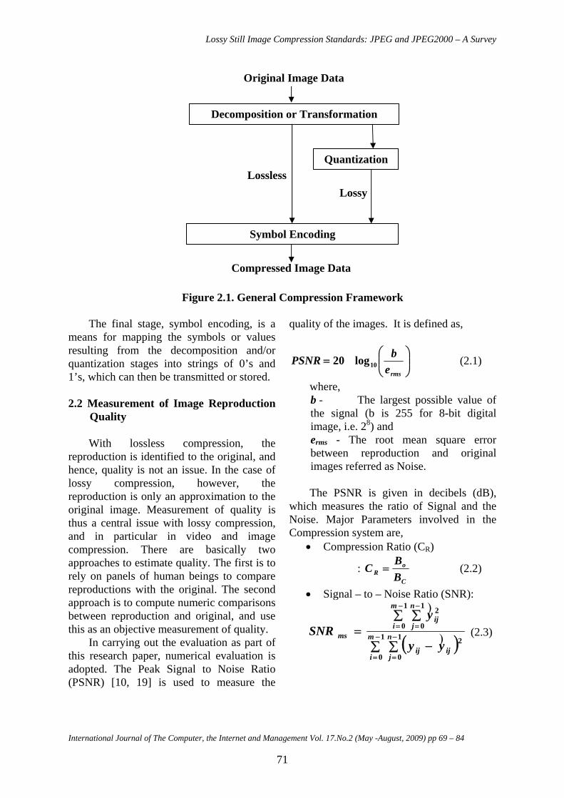
Figure 2.1 shows the general compression scheme which consists of three basic components: (1) image decomposition or transformation (2) Quantization [10, 15] and (3) Symbol encoding [10, 15]. The image decomposition or transformation is usually a reversible operation and is performed to eliminate the redundant information, or more generally, to provide a representation that is more amenable to efficient coding. Both lossless and lossy techniques are used in this stage. Next stage, quantization, is a many-to-one mapping found only in lossy techniques, and invariably leads to introduction of errors at this stage.
70
Lossy Still Image Compression Standards: JPEG and JPEG2000 – A Survey
Original Image Data
Decomposition or Transformation
Quantization
Symbol Encoding
Lossless Lossy
Compressed Image Data
Figure 2.1. General Compression Framework
The final stage, symbol encoding, is a means for mapping the symbols or values resulting from the decomposition and/or quantization stages into strings of 0’s and 1’s, which can then be transmitted or stored.
2.2 Measurement of Image Reproduction
Quality With lossless compression, the
reproduction is identified to the original, and hence, quality is not an issue. In the case of lossy compression, however, the reproduction is only an approximation to the original image. Measurement of quality is thus a central issue with lossy compression, and in particular in video and image compression. There are basically two approaches to estimate quality. The first is to rely on panels of human beings to compare reproductions with the original. The second approach is to compute numeric comparisons between reproduction and original, and use this as an objective measurement of quality.
In carrying out the evaluation as part of this research paper, numerical evaluation is adopted. The Peak Signal to Noise Ratio (PSNR) [10, 19] is used to measure the
quality of the images. It is defined as,
⎟⎟⎠
⎞⎜⎜⎝
⎛=
rmsebPSNR 10log20 (2.1)
where, b - The largest possible value of the signal (b is 255 for 8-bit digital image, i.e. 28) and erms - The root mean square error between reproduction and original images referred as Noise. The PSNR is given in decibels (dB),
which measures the ratio of Signal and the Noise. Major Parameters involved in the Compression system are,
• Compression Ratio (CR)
: C
oR B
BC = (2.2)
• Signal – to – Noise Ratio (SNR):
( )∑ ∑ −
∑ ∑= −
=
−
=
−
=
−
=1
0
1
0
2
1
0
1
0
2
m
i
n
jijij
m
i
n
jij
msyy
ySNR )
)
(2.3)
International Journal of The Computer, the Internet and Management Vol. 17.No.2 (May -August, 2009) pp 69 – 84
71
S.N. Sivanandam, A. Pasumpon Pandian and P. Rani
• Root Mean Square Error (erms):
( )∑ ∑−
=
−
=−=
1
0
1
0
21 m
i
n
jijijrms yy
mne )
(2.4)
where, Bo – Number of bytes needed to store the original image
Bc – Number of bytes needed to store the compressed image m & n – Spatial coordinate value Y - Original image Y - Reconstructed image ˆ
3. JPEG Standard This is the very well known ISO/ITU-T
standard created in the late 1980s. There are several modes defined for JPEG [14, 15, 26], including baseline, lossless, progressive and hierarchical. The baseline mode is the most popular one and supports lossy coding only. The lossless mode is not popular but provides for lossless coding, although it does not support lossy.
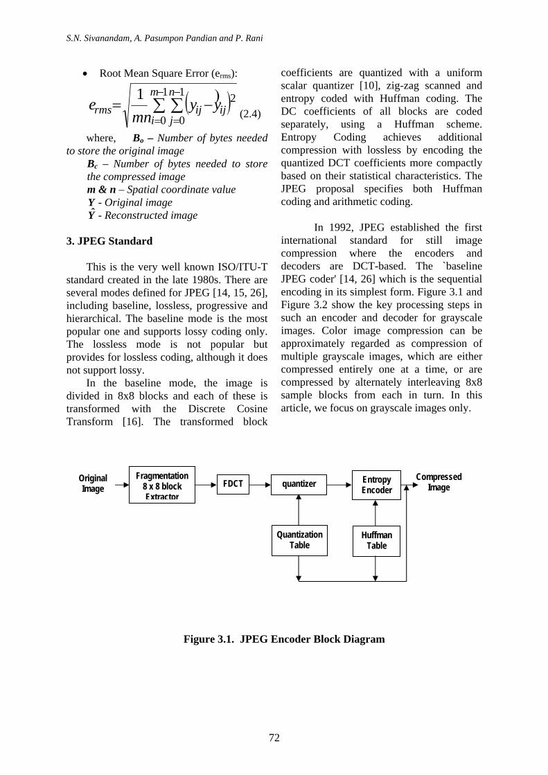
In the baseline mode, the image is divided in 8x8 blocks and each of these is transformed with the Discrete Cosine Transform [16]. The transformed block
coefficients are quantized with a uniform scalar quantizer [10], zig-zag scanned and entropy coded with Huffman coding. The DC coefficients of all blocks are coded separately, using a Huffman scheme. Entropy Coding achieves additional compression with lossless by encoding the quantized DCT coefficients more compactly based on their statistical characteristics. The JPEG proposal specifies both Huffman coding and arithmetic coding.
In 1992, JPEG established the first
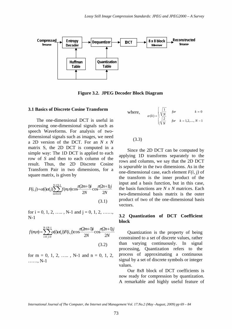
international standard for still image compression where the encoders and decoders are DCT-based. The `baseline JPEG coder' [14, 26] which is the sequential encoding in its simplest form. Figure 3.1 and Figure 3.2 show the key processing steps in such an encoder and decoder for grayscale images. Color image compression can be approximately regarded as compression of multiple grayscale images, which are either compressed entirely one at a time, or are compressed by alternately interleaving 8x8 sample blocks from each in turn. In this article, we focus on grayscale images only.
Fragmentation 8 x 8 block Extractor
FDCT quantizer Entropy
Encoder Original Image
CompressedImage
Quantization Table
Huffman Table
Figure 3.1. JPEG Encoder Block Diagram
72
Lossy Still Image Compression Standards: JPEG and JPEG2000 – A Survey
Reconstructed
Figure 3.2. JPEG Decoder Block Diagram
3.1 Basics of Discrete Cosine Transform The one-dimensional DCT is useful in
processing one-dimensional signals such as speech Waveforms. For analysis of two-dimensional signals such as images, we need a 2D version of the DCT. For an N x N matrix S, the 2D DCT is computed in a simple way: The 1D DCT is applied to each row of S and then to each column of the result. Thus, the 2D Discrete Cosine Transform Pair in two dimensions, for a square matrix, is given by
Njn
NimnmfjijiF
N
m
N
n 2)12(cos
2)12(cos),()()(),(
1
0
1
0
++= ∑∑
−
=
−
=
ππαα
(3.1)
for i = 0, 1, 2, ….. , N-1 and j = 0, 1, 2, ……, N-1
Njn
NimjiFjinmf
N
i
N
j 2)12(cos
2)12(cos),()()(),(
1
0
1
0
++=∑∑
−
=
−
=
ππαα
(3.2)
for m = 0, 1, 2, ….. , N-1 and n = 0, 1, 2, ……, N-1
where,
⎪⎪⎩
⎪⎪⎨
⎧
−=
==
1,....,2,12
01
)(Nkfor
N
kforNkα
(3.3)
Since the 2D DCT can be computed by
applying 1D transforms separately to the rows and columns, we say that the 2D DCT is separable in the two dimensions. As in the one-dimensional case, each element F(i, j) of the transform is the inner product of the input and a basis function, but in this case, the basis functions are N x N matrices. Each two-dimensional basis matrix is the outer product of two of the one-dimensional basis vectors.
3.2 Quantization of DCT Coefficient block
Quantization is the property of being
constrained to a set of discrete values, rather than varying continuously. In signal processing, Quantization refers to the process of approximating a continuous signal by a set of discrete symbols or integer values.
Our 8x8 block of DCT coefficients is now ready for compression by quantization. A remarkable and highly useful feature of
Entropy Decoder
IDCT Dequantizer 8 x 8 block Merger
Compressed Image Image
Quantization Table
Huffman Table
International Journal of The Computer, the Internet and Management Vol. 17.No.2 (May -August, 2009) pp 69 – 84
73
S.N. Sivanandam, A. Pasumpon Pandian and P. Rani
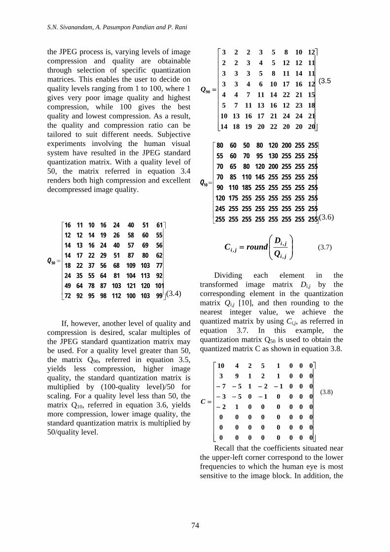
the JPEG process is, varying levels of image compression and quality are obtainable through selection of specific quantization matrices. This enables the user to decide on quality levels ranging from 1 to 100, where 1 gives very poor image quality and highest compression, while 100 gives the best quality and lowest compression. As a result, the quality and compression ratio can be tailored to suit different needs. Subjective experiments involving the human visual system have resulted in the JPEG standard quantization matrix. With a quality level of 50, the matrix referred in equation 3.4 renders both high compression and excellent decompressed image quality.
⎥⎥⎥⎥⎥⎥⎥⎥⎥⎥⎤
⎢⎢⎢⎢⎢⎢⎢⎢⎢⎢⎡
=
101120121103877864499211310481645535247710310968563722186280875129221714566957402416131455605826191412126151402416101116
50Q
⎦⎣ 9910310011298959272 (3.4)
If, however, another level of quality and
compression is desired, scalar multiples of the JPEG standard quantization matrix may be used. For a quality level greater than 50, the matrix Q90, referred in equation 3.5, yields less compression, higher image quality, the standard quantization matrix is multiplied by (100-quality level)/50 for scaling. For a quality level less than 50, the matrix Q10, referred in equation 3.6, yields more compression, lower image quality, the standard quantization matrix is multiplied by 50/quality level.
⎥⎥⎥⎥⎥⎥⎥⎥⎥⎥⎥
⎦
⎤
⎢⎢⎢⎢⎢⎢⎢⎢⎢⎢⎢
⎣
⎡
=
2020202220191814212424211716131018231216131175152122141174412161710643311141185333111212543221210853223
90Q(3.5
⎥⎥⎥⎥⎥⎥⎥⎥⎥⎥
⎦
⎤
⎢⎢⎢⎢⎢⎢⎢⎢⎢⎢
⎣
⎡
=
2552552552552552552552552552552552552552552552452552552552552552551751202552552552552551851109025525525525514511085702552552552001208065702552552551309570605525525520012080506080
10Q
(3.6)
⎟⎟⎠
⎞⎜⎜⎝
⎛=
ji
jiji Q
DroundC
,
,, (3.7)
Dividing each element in the
transformed image matrix Di,j by the corresponding element in the quantization matrix Qi,j [10], and then rounding to the nearest integer value, we achieve the quantized matrix by using Ci,j, as referred in equation 3.7. In this example, the quantization matrix Q50 is used to obtain the quantized matrix C as shown in equation 3.8.
⎥⎥⎥⎥⎥⎥⎥⎥⎥⎥⎥
⎦
⎤
⎢⎢⎢⎢⎢⎢⎢⎢⎢⎢⎢
⎣
⎡
−−−−
−−−−
=
00000000000000000000000000000012000010530001215700012193000152410
C (3.8)
Recall that the coefficients situated near the upper-left corner correspond to the lower frequencies to which the human eye is most sensitive to the image block. In addition, the
74
Lossy Still Image Compression Standards: JPEG and JPEG2000 – A Survey
3.4 Huffman Encoding & Decoding zeros represent the less important, higher frequencies that have been discarded, giving rise to the lossy part of compression. As mentioned earlier, only the remaining nonzero coefficients will be used to reconstruct the image. It is also interesting to note the effect of different quantization matrices; use of Q10 would give C significantly more zeros, while Q90 would result in very few zeroes.
Entropy Coding achieves additional
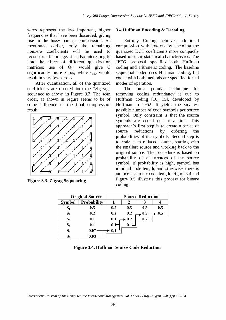
compression with lossless by encoding the quantized DCT coefficients more compactly based on their statistical characteristics. The JPEG proposal specifies both Huffman coding and arithmetic coding. The baseline sequential codec uses Huffman coding, but codec with both methods are specified for all modes of operation. After quantization, all of the quantized
coefficients are ordered into the "zig-zag" sequence as shown in Figure 3.3. The scan order, as shown in Figure seems to be of some influence of the final compression result.
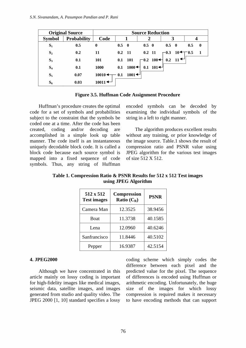
The most popular technique for removing coding redundancy is due to Huffman coding [10, 15], developed by Huffman in 1952. It yields the smallest possible number of code symbols per source symbol. Only constraint is that the source symbols are coded one at a time. This approach’s first step is to create a series of source reductions by ordering the probabilities of the symbols. Second step is to code each reduced source, starting with the smallest source and working back to the original source. The procedure is based on probability of occurrences of the source symbol, if probability is high, symbol has minimal code length, and otherwise, there is an increase in the code length. Figure 3.4 and Figure 3.5 illustrate this process for binary coding.
1 0 0 1 1 1 1 0
1 0 0 1 1 1 1 0
1 0 0 1 1 1 1 0
1 0 0 1 1 1 1 0
1 0 0 1 1 1 1 0
1 0 0 1 1 1 1 0
1 0 0 1 1 1 1 0
1 0 0 1 1 1 1 0
Figure 3.3. Zigzag Sequencing
Original Source Source Reduction Symbol Probability 1 2 3 4
S1 0.5 0.5 0.5 0.5 0.5 S2 0.2 0.2 0.2 0.3 0.5 S3 0.1 0.1 0.2 0.2 S4 0.1 0.1 0.1 S5 0.07 0.1 S6 0.03
Figure 3.4. Huffman Source Code Reduction
International Journal of The Computer, the Internet and Management Vol. 17.No.2 (May -August, 2009) pp 69 – 84
75
S.N. Sivanandam, A. Pasumpon Pandian and P. Rani
Original Source Source Reduction
Symbol Probability Code 1 2 3 4 S1 0.5 0 0.5 0 0.5 0 0.5 0 0.5 0
S2 0.2 11 0.2 11 0.2 11 0.3 10 0.5 1
S3 0.1 101 0.1 101 0.2 100 0.2 11
S4 0.1 1000 0.1 1000 0.1 101
S5 0.07 10010 0.1 1001
S6 0.03 10011
Figure 3.5. Huffman Code Assignment Procedure
Huffman’s procedure creates the optimal
code for a set of symbols and probabilities subject to the constraint that the symbols be coded one at a time. After the code has been created, coding and/or decoding are accomplished in a simple look up table manner. The code itself is an instantaneous uniquely decodable block code. It is called a block code because each source symbol is mapped into a fixed sequence of code symbols. Thus, any string of Huffman
encoded symbols can be decoded by examining the individual symbols of the string in a left to right manner.
The algorithm produces excellent results
without any training, or prior knowledge of the image source. Table.1 shows the result of compression ratio and PSNR value using JPEG algorithm for the various test images of size 512 X 512.
Table 1. Compression Ratio & PSNR Results for 512 x 512 Test images
using JPEG Algorithm
512 x 512 Test images
Compression Ratio (CR) PSNR
Camera Man 12.3525 38.9456
Boat 11.3738 40.1585
Lena 12.0960 40.6246
Sanfrancisco 11.8446 40.5102
Pepper 16.9387 42.5154
4. JPEG2000 Although we have concentrated in this
article mainly on lossy coding is important for high-fidelity images like medical images, seismic data, satellite images, and images generated from studio and quality video. The JPEG 2000 [1, 10] standard specifies a lossy
coding scheme which simply codes the difference between each pixel and the predicted value for the pixel. The sequence of differences is encoded using Huffman or arithmetic encoding. Unfortunately, the huge size of the images for which lossy compression is required makes it necessary to have encoding methods that can support
76
Lossy Still Image Compression Standards: JPEG and JPEG2000 – A Survey
storage and progressive transmission of images at a spectrum of resolutions.
JPEG 2000 is based on the discrete
wavelet transform (DWT), scalar quantization, context modeling, entropy coding and post-compression rate allocation. The DWT is dyadic and can be performed with either the reversible Le Gall (5, 3) taps filter [11], which provides for lossless coding, or the non-reversible Daubechies (9, 7) taps bi-orthogonal filter [6], which provides for higher compression but does not do lossless. The quantizer follows an embedded dead-zone scalar approach and is independent for each sub-band. Each sub-band is divided into rectangular blocks, called code-blocks in JPEG 2000, typically 64x64, and entropy coded using context modeling and bit-plane arithmetic coding.
Over the past few years, a variety of
novel and sophisticated wavelet-based image coding schemes have been developed. These include EZW [20], SPIHT [19], SFQ [27], CREW [2], EPWIC [3], EBCOT [22], SR [23], Second Generation Image Coding [8],
Image Coding using Wavelet Packets, Wavelet Image Coding using VQ [9, 10], and Lossless Image Compression using Integer Lifting [4]. This list is by no means exhaustive and many more such innovative techniques are being developed. Here we concentrate only on JPEG2000 lossy still image compression algorithm.
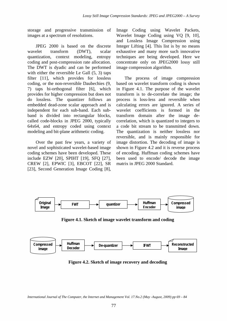
The process of image compression
based on wavelet transform coding is shown in Figure 4.1. The purpose of the wavelet transform is to de-correlate the image; the process is loss-less and reversible when calculating errors are ignored. A series of wavelet coefficients is formed in the transform domain after the image de-correlation, which is quantized to integers to a code bit stream to be transmitted down. The quantization is neither lossless nor reversible, and is mainly responsible for image distortion. The decoding of image is shown in Figure 4.2 and it is reverse process of encoding. Huffman coding schemes have been used to encode/ decode the image matrix in JPEG 2000 Standard.
Figure 4.1. Sketch of image wavelet transform and coding
Figure 4.2. Sketch of image recovery and decoding
Huffman Decoder De-quantizer IFWT Reconstructed
Image Compressed
image
FWT quantizer Huffman Encoder
Original Image
Compressed image
International Journal of The Computer, the Internet and Management Vol. 17.No.2 (May -August, 2009) pp 69 – 84
77
S.N. Sivanandam, A. Pasumpon Pandian and P. Rani
4.1 Basics of Discrete Wavelet Transform
The Discrete Wavelet Transform of a
finite length signal x(n) having N components, for example, is expressed by an N x N matrix. Wavelets [5, 7] are functions defined over a finite interval and having an average value of zero. The basic idea of the wavelet transform is to represent any arbitrary function (t) as a superposition of a set of such wavelets or basis functions. These basis functions or baby wavelets are obtained from a single prototype wavelet called the mother wavelet, by dilations or contractions (scaling) and translations (shifts).
Based on the property of separability, scalability and Translatability, the kernel of the forward transform can be represented as three separable 2-D wavelets. There exist various extensions of the one-dimensional wavelet transform to two-dimensional and indeed multi-dimensional wavelet, but separable two-dimensional wavelets are simple and effective in common use. Same as in the construction of one-dimensional wavelet, the scale function ϕ(x, y) is defined as
ϕ(x, y) = ϕ (x) ϕ (y) (4.1)
where ϕ (x), ϕ (y) are the one-dimensional scale functions. Suppose ψ(x) denotes the wavelet function related to the one-dimensional scale function, then three 2-D wavelets are defined by,
)()(),()()(),()()(),(
yxyxyxyxyxyx
D
V
H
ψψψ
ψϕψ
ϕψψ
=
=
=
are called horizontal, vertical and
diagonal wavelets respectively. Both ϕ(x) and ψ(x) can be expressed as
linear combinations of double resolution copies, i.e.,
∑
∑
−=
−=
n
n
nxnhx
nxnhx
)2(2)()(
)2(2)()(
ϕψ
ϕϕ
ψ
ϕ
where hϕ and hψ are called scaling and wavelet vectors.
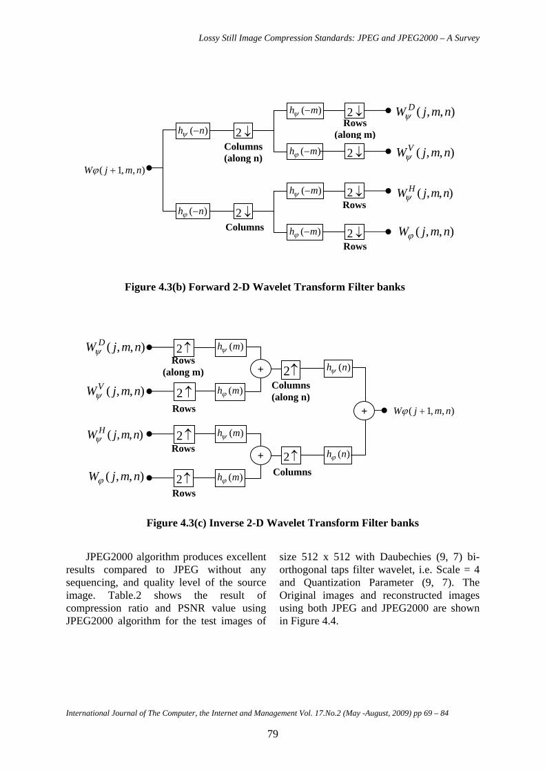
The Wϕ(j, m, n) and { Wiψ(j, m, n) for i
= H, V, D } outputs are the DWT coefficients at scale j. The series of filtering and down-sampling operations have been used to compute WH
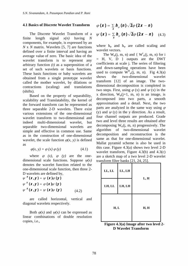
ψ(j, m, n). Fig 4.3(a) shows the two-dimensional wavelet transform [12] of an image. The two-dimensional decomposition is completed in two steps. First, using ϕ (x) and ψ (x) in the x direction, Wϕ(j+1, m, n) is an image, is decomposed into two parts, a smooth approximation and a detail. Next, the two parts are analyzed in the same way using ϕ (y) and ψ (y) in the y direction. As a result, four channel outputs are produced. Grade two and level three results are obtained after decomposing Wϕ(j, m, n) progressively. The algorithm of two-dimensional wavelet decomposition and reconstruction is the same as that for one-dimensional wavelet. Mallat pyramid scheme is also be used in this case. Figure 4.3(a) shows two level 2-D wavelet transform, Figure 4.3(b) and 4.3(c) are a sketch map of a two level 2-D wavelet transform filter banks [21, 24, 25].
LL, LL LL, LH
LH, LL
L, H
LH, LH
H, L H, H
(4.3)
(4.2)
Figure 4.3(a) Image after two level 2-D Wavelet Transform
78
Lossy Still Image Compression Standards: JPEG and JPEG2000 – A Survey
)( nh −ψ
↓2
)( nh −ϕ ↓2
)( mh −ψ ↓2
)( mh −ϕ ↓2
)( mh −ψ ↓2
)( mh −ϕ ↓2
),,1( nmjW +ϕ
),,( nmjW Dψ
),,( nmjWVψ
),,( nmjW Hψ
),,( nmjWϕ
Columns(along n)
Rows (along m)
Columns
Rows
Rows
Figure 4.3(b) Forward 2-D Wavelet Transform Filter banks
)(nhψ↑2
)(nhϕ↑2
)(mhψ↑2
)(mhϕ↑2
)(mhψ↑2
)(mhϕ↑2
),,1( nmjW +ϕ
),,( nmjW Dψ
),,( nmjWVψ
),,( nmjW Hψ
),,( nmjWϕ
Columns(along n)
Rows (along m)
Columns
Rows
Rows
Rows
+
+
+
Figure 4.3(c) Inverse 2-D Wavelet Transform Filter banks
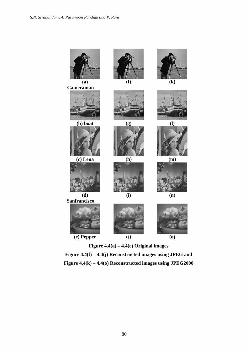
JPEG2000 algorithm produces excellent
results compared to JPEG without any sequencing, and quality level of the source image. Table.2 shows the result of compression ratio and PSNR value using JPEG2000 algorithm for the test images of
size 512 x 512 with Daubechies (9, 7) bi-orthogonal taps filter wavelet, i.e. Scale = 4 and Quantization Parameter (9, 7). The Original images and reconstructed images using both JPEG and JPEG2000 are shown in Figure 4.4.
International Journal of The Computer, the Internet and Management Vol. 17.No.2 (May -August, 2009) pp 69 – 84
79
S.N. Sivanandam, A. Pasumpon Pandian and P. Rani
Figure 4.4(a) – 4.4(e) Original images
Figure 4.4(f) – 4.4(j) Reconstructed images using JPEG and
Figure 4.4(k) – 4.4(o) Reconstructed images using JPEG2000
(a)
Cameraman (f)
(k)
(b) boat (g)
(l)
(c) Lena (h)
(m)
(d)
Sanfrancisco (i)
(n)
(e) Pepper (j)
(o)
80
Lossy Still Image Compression Standards: JPEG and JPEG2000 – A Survey
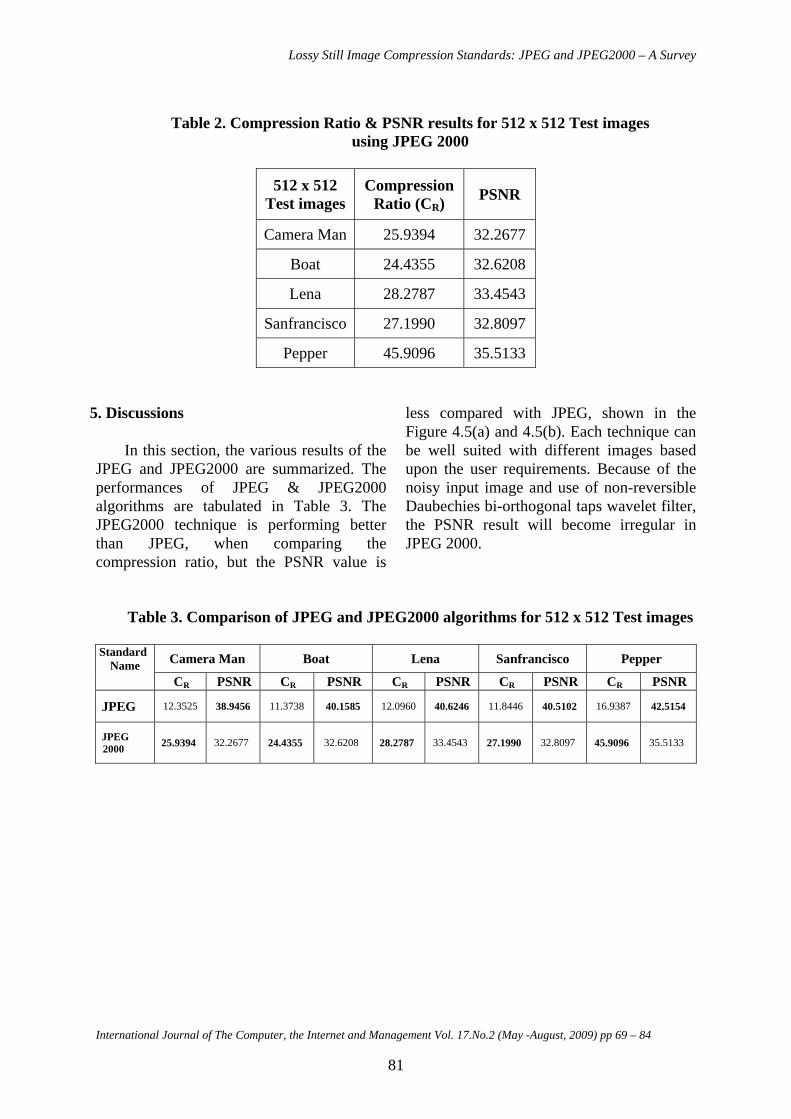
Table 2. Compression Ratio & PSNR results for 512 x 512 Test images
using JPEG 2000
512 x 512 Test images
Compression Ratio (CR) PSNR
Camera Man 25.9394 32.2677
Boat 24.4355 32.6208
Lena 28.2787 33.4543
Sanfrancisco 27.1990 32.8097
Pepper 45.9096 35.5133
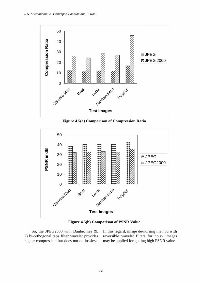
5. Discussions In this section, the various results of the
JPEG and JPEG2000 are summarized. The performances of JPEG & JPEG2000 algorithms are tabulated in Table 3. The JPEG2000 technique is performing better than JPEG, when comparing the compression ratio, but the PSNR value is
less compared with JPEG, shown in the Figure 4.5(a) and 4.5(b). Each technique can be well suited with different images based upon the user requirements. Because of the noisy input image and use of non-reversible Daubechies bi-orthogonal taps wavelet filter, the PSNR result will become irregular in JPEG 2000.
Table 3. Comparison of JPEG and JPEG2000 algorithms for 512 x 512 Test images
Standard Name Camera Man Boat Lena Sanfrancisco Pepper
CR PSNR CR PSNR CR PSNR CR PSNR CR PSNR
JPEG 12.3525 38.9456 11.3738 40.1585 12.0960 40.6246 11.8446 40.5102 16.9387 42.5154
JPEG 2000 25.9394 32.2677 24.4355 32.6208 28.2787 33.4543 27.1990 32.8097 45.9096 35.5133
International Journal of The Computer, the Internet and Management Vol. 17.No.2 (May -August, 2009) pp 69 – 84
81
S.N. Sivanandam, A. Pasumpon Pandian and P. Rani
0
10
20
30
40
50
Camera
Man
Boat
Lena
Sanfra
ncisc
o
Peppe
r
Test Images
Com
pres
sion
Rat
io
JPEGJPEG 2000
Figure 4.5(a) Comparison of Compression Ratio
0
10
20
30
40
50
Camera
Man
Boat
Lena
Sanfra
ncisc
o
Peppe
r
Test Images
PSN
R in
dB
JPEGJPEG2000
Figure 4.5(b) Comparison of PSNR Value
So, the JPEG2000 with Daubechies (9,
7) bi-orthogonal taps filter wavelet provides higher compression but does not do lossless.
In this regard, image de-noising method with reversible wavelet filters for noisy images may be applied for getting high PSNR value.
82
Lossy Still Image Compression Standards: JPEG and JPEG2000 – A Survey
6. Conclusion Image compression is the key
technology for managing images in digital format. This survey paper has been focused on the development of efficient and effective algorithms for still image compression. Fast and efficient lossy coding algorithms JPEG and JPEG2000 for image Compression/Decompression using Discrete Cosine and Fast Wavelet Transform are discussed with Huffman coding schemes. The parameters compression ratio and Peak Signal-to-Noise Ratio (PSNR) is compared for JPEG and JPEG2000 algorithms with 512 x 512 test images. JPEG2000 is providing the quality at Maximum compression ratio with optimum PSNR Value.
References
[1] Athanassios Skodras, Charilaos
Christopoulos, and Touradj Ebrahimi (2001), “The JPEG 2000 Still Image Compression Standard”, IEEE Signal Processing Magazine, 1053-5888/01, pp 36-58, Sep.
[2] Boliek M., Gormish M.J., Schwartz E.L. and Keith A. (1997), “Next Generation Image Compression and Manipulation Using CREW”, Proceedings of IEEE ICIP.
[3] Buccigrossi R. and Simoncelli E.P., “EPWIC: Embedded Predictive Wavelet Image Coder”, GRASP Laboratory, TR #414.
[4] Calderbank R.C., Daubechies I., Sweldens W. and Yeo B.L. (1998), “Wavelet Transforms that Map Integers to Integers”, Applied and Computational Harmonic Analysis (ACHA), Vol.5, No.3, pp 332-369.
[5] Chan Y.T. (1995), Wavelet Basics, Kluwer Academic Publishers, Norwell, MA.
[6] Cohen A., Daubechies I. and Feauveau J.C.(1992), “Biorthogonal Bases of Compactly Supported Wavelets”, Communication on Pure and Applied Mathematics, Vol.XLV, pp 485-560.
[7] Daubechies I. (1988), “Orthonormal Bases of Compactly Supported Wavelets”, Communication on Pure and Applied Mathematics, Vol.41, pp 909-996, Nov.
[8] Froment J. and Mallat S. (1992), “Second generation compact image coding with wavelets”, in Wavelets - A Tutorial in Theory and Applications, New York, Academic Press, pp. 655-678, January.
[9] Gersho A. and Gray R.M. (1991), Vector Quantization and Signal Compression, Kluwer Academic Publishers.
[10] Khalid Sayood (2006), Introduction to Data Compression, 3/e, Morgan Kaufmann Publishers, Elsevier Inc., San Francisco, CA.
[11] Le Gall D. and Tabatabai A. (1988), “Sub-band coding of digital images using symmetric short kernel filters and arithmetic coding techniques”, Proceedings of the IEEE International Conference on Acoustics, Speech and Signal Processing, New York, USA, pp 761-765.
[12] Lewis A.S. and Knowles G. (1992), “Image Compression Using the 2-D Wavelet Transform”, IEEE Transaction on Image Processing, Vol.1, No.2, pp 244-250, Apr.
[13] Mallat S.G. (1989), “A Theory for Multiresolution Signal Decomposition: The Wavelet Representation”, IEEE Transaction on Pattern Analysis and Machine Intelligence, Vol.11, No.7, pp 674-693, Jul.
[14] Pennebaker W.B. and Mitchell J.L. (1993), “JPEG - Still Image Data Compression Standards”, Van Nostrand Reinhold.
International Journal of The Computer, the Internet and Management Vol. 17.No.2 (May -August, 2009) pp 69 – 84
83
S.N. Sivanandam, A. Pasumpon Pandian and P. Rani
[15] Rafael C. Gonzalez and Richard E.
Woods (2002), Digital Image Processing, 2/e, Prentice Hall.
[16] Rao K.R. and Yip P. (1990), Discrete Cosine Transforms - Algorithms, Advantages, Applications, Academic Press.
[17] Saha S. and Vemuri R. (1999), “Adaptive Wavelet Coding of Multimedia Images”, Proceedings of ACM Multimedia Conference, Nov.
[18] Said A. and Pearlman W.A.(1993), “Reversible image compression via multi resolution representation and predictive coding, in: Visual Communications and Image Processing”, Proceedings of the SPIE, Cambridge, MA, USA, Vol. 2094, pp 664–674, Nov.
[19] Said A. and Pearlman W.A. (1996), “A New, Fast, and Efficient Image Codec Based on Set Partitioning in Hierarchical Trees”, IEEE Transaction on Circuits and Systems–Video Technology, Vol.6, No.3, pp 243-250, June.
[20] Shapiro J.M. (1993), “Embedded Image Coding Using Zerotrees of Wavelet Coefficients”, IEEE Transaction on Signal Processing, Vol.41, No.12, pp 3445-3462, Dec.
[21] Strang G. and Nguyen T. (1996), “Wavelets and Filter Banks”, Wellesley-Cambridge Press, Wellesley, MA.
[22] Taubman D. (1999), “High Performance Scalable Image Compression with EBCOT”, IEEE Transaction Image Processing, March.
[23] Tsai M.J., Villasenor J.D. and Chen F. (1996), “Stack-Run Image Coding”, IEEE Transaction on Circuits and Systems-Video Technology, Vol.6, No.5, pp 519-521, Oct.
[24] Vaidyanathan P.P. (1993), Multirate Systems and Filter Banks, Prentice Hall, Englewood Cliffs, N.J.
[25] Vetterli M. and Herley C. (1992), “Wavelets and Filter Banks: Theory and Design”, IEEE Transaction on Signal Processing, Vol.40, No.9, pp 2207-2232, September.
[26] Wallace G. K. (1991), “The JPEG Still Picture Compression Standard”, Communication of ACM, Vol.34, No.4, pp 30-44, Apr.
[27] Xiong Z., Ramachandran K. and Orchard M. T. (1997), “Space-Frequency Quantization for Wavelet Image Coding”, IEEE Transaction on Image Processing, Vol.6, No.5, pp 677-693, May.
84


![Chapter 1 CUDA-Accelerated HD-ODETLAP: Lossy High ...wrf/p/165-2013-hdodetlap.pdf · For example, JPEG 2000 [24] uses irreversible and reversible wavelet transform for its lossy and](https://static.fdocuments.in/doc/165x107/5e7bc4b2142228718b5a0653/chapter-1-cuda-accelerated-hd-odetlap-lossy-high-wrfp165-2013-for-example.jpg)


![Image and Vision Computing Recognition... · JPEG2000 [15] being the obvious choice for compression standards. We feel that common image compression standards, such as JPEG and JPEG2000,](https://static.fdocuments.in/doc/165x107/5ffb188cbb2de95845748969/image-and-vision-computing-recognition-jpeg2000-15-being-the-obvious-choice.jpg)