The Inverse Kinematics approach in the FOOT experiment La presente tesi si propone di fornire una...
70
Alma Mater Studiorum · Universit ` a di Bologna Scuola di Scienze Dipartimento di Fisica e Astronomia Corso di Laurea in Fisica The Inverse Kinematics approach in the FOOT experiment Relatore: Prof. Antonio Zoccoli Correlatore: Dott. Roberto Spighi Presentata da: Celeste Ottaviani Anno Accademico 2017/2018
-
Upload
truongxuyen -
Category
Documents
-
view
215 -
download
0
Transcript of The Inverse Kinematics approach in the FOOT experiment La presente tesi si propone di fornire una...

Alma Mater Studiorum · Universita di Bologna
Scuola di Scienze
Dipartimento di Fisica e Astronomia
Corso di Laurea in Fisica
The Inverse Kinematics approach
in the FOOT experiment
Relatore:
Prof.
Antonio Zoccoli
Correlatore:
Dott.
Roberto Spighi
Presentata da:
Celeste Ottaviani
Anno Accademico 2017/2018

2

Sommario
La presente tesi si propone di fornire una descrizione approfondita dell’approccio della Cinema-tica Inversa applicata all’esperimento FOOT (FragmentatiOn Of Target). Tale esperimento estato sviluppato con lo scopo di migliorare la conoscenza dell’efficacia biologica degli ioni impie-gati nella cura delle neoplasie tramite la misura delle sezioni d’urto differenziali dei processi diframmentazione nucleare che si verificano nei trattamenti di adroterapia. Tuttavia, nella praticasperimentale si presenta l’impossibilita di ottenere queste misure; i frammenti generati nella di-sintegrazione dei nuclei nei tessuti del paziente hanno energia cinetica molto bassa e rimangonointrappolati nel bersaglio senza poter essere rivelati dall’apparato. Una possibile soluzione con-siste nell’impiegare un bersaglio a bassa densita (al limite gassoso), con spessore micrometrico.Questo, pero, comporterebbe una drastica riduzione della probabilita di interazione e lunghitempi di presa dati. FOOT utilizza, invece, un approccio di cinematica inversa che permettel’inversione dei ruoli di fascio e bersaglio; la frammentazione del bersaglio viene infatti studiatautilizzando fasci di nuclei pesanti contro bersagli ricchi di idrogeno e applicando successivamenteuna trasformazione di Lorentz ai frammenti prodotti. Questa stessa tecnica si estende anche alcaso in cui il proiettile sia costituito da nuclei pesanti che, invece, favoriscono la frammentazionesia del fascio che del bersaglio.Lo scopo del lavoro di tesi consiste, pertanto, nel fornire un resoconto completo e dettagliatodella Cinematica Inversa sopperendo alla mancanza di documentazione sull’argomento. Sonostati delineati i problemi sperimentali, i vantaggi derivanti dall’applicazione di questa tecnica esi e accennato alla struttura matematica di base. Si e mostrata inoltre la validita dell’approccioconfrontando plot di distribuzione di energia cinetica di frammenti ottenuti da simulazioni incinematica diretta ed inversa.
3

4

Abstract
This thesis is intended to provide an in-depth description of the Inverse Kinematics approachapplied to the FOOT (FragmentatiOn Of Target) experiment. This experiment was developedwith the goal of improving the knowledge of the biological effectiveness of ions employed in theneoplasms treatment through the measurement of the differential cross section of the nuclearfragmentation processes that take place during hadrontherapy. However, in the experimentalpractice arises the inability of obtaining these measurements; the fragments produced in thepatient’s tissues disintegration have a really low kinetic energy and remain trapped inside thetarget without possibility of being detected. A possible solution consists in the employment ofa low density target (even gaseous), with a micrometric thickness; however, this would causea drastic reduction of the interaction probability and the required times for the data takingwould be extremely long. Therefore, FOOT takes advantage of an Inverse Kinematic approachin which the projectile and target roles are switched; this way the target fragmentation can bestudied with the use of heavy ions beams against enriched Hydrogen targets and successivelyapplying a Lorentz boost on the produced fragments. This same approach can be extended tothe case in which the beam is made up of heavy nuclei that, in the collision, cause the productionof both beam and target fragments.The present thesis therefore supplies a complete and detailed report of the Inverse Kinematicsproviding for the lack of a good formulation of this topic. In this work, the experimental problemsand the advantages deriving from the application of this method were delineated along with thebasic mathematical structure. It has been shown the validity of this approach through the com-parison of kinetic energy distributions for the fragments, obtained from simulated interactionsin direct and inverse kinematics.
5

6

Contents
Introduction 9
1 Ionizing radiations in medical treatments 11
1.1 Biological effects of Radiation . . . . . . . . . . . . . . . . . . . . . . . . . . . . . 11
1.1.1 Radiation induced damage . . . . . . . . . . . . . . . . . . . . . . . . . . 11
1.1.2 Absorbed Dose . . . . . . . . . . . . . . . . . . . . . . . . . . . . . . . . . 13
1.1.3 Linear Energy Transfer . . . . . . . . . . . . . . . . . . . . . . . . . . . . 13
1.1.4 Relative Biological Effectiveness . . . . . . . . . . . . . . . . . . . . . . . 14
1.1.5 Oxygen Enhancement Ratio . . . . . . . . . . . . . . . . . . . . . . . . . 15
1.2 Interaction of Heavy Charged Particles with Matter . . . . . . . . . . . . . . . . 17
1.2.1 The Bethe-Bloch formula and Stopping Power . . . . . . . . . . . . . . . 17
1.2.2 Range . . . . . . . . . . . . . . . . . . . . . . . . . . . . . . . . . . . . . . 19
1.2.3 Multiple Scattering . . . . . . . . . . . . . . . . . . . . . . . . . . . . . . . 20
1.2.4 Nuclear Fragmentation . . . . . . . . . . . . . . . . . . . . . . . . . . . . . 21
1.3 Application in Cancer Treatment . . . . . . . . . . . . . . . . . . . . . . . . . . . 24
1.3.1 Radiotherapy . . . . . . . . . . . . . . . . . . . . . . . . . . . . . . . . . . 24
1.3.2 Hadrontherapy . . . . . . . . . . . . . . . . . . . . . . . . . . . . . . . . . 26
1.4 Proton RBE . . . . . . . . . . . . . . . . . . . . . . . . . . . . . . . . . . . . . . . 30
2 The FOOT Experiment 33
2.1 The aim of the experiment . . . . . . . . . . . . . . . . . . . . . . . . . . . . . . . 34
2.1.1 Target fragmentation and RBE variability . . . . . . . . . . . . . . . . . . 34
2.1.2 Projectile fragmentation for Carbon beams . . . . . . . . . . . . . . . . . 34
2.1.3 Projectile fragmentation for Oxygen beams . . . . . . . . . . . . . . . . . 34
2.1.4 Projectile fragmentation for Helium beams . . . . . . . . . . . . . . . . . 34
2.1.5 Radioprotection in Space . . . . . . . . . . . . . . . . . . . . . . . . . . . 35
2.2 The experimental setup . . . . . . . . . . . . . . . . . . . . . . . . . . . . . . . . 36
2.2.1 Start Counter . . . . . . . . . . . . . . . . . . . . . . . . . . . . . . . . . . 36
2.2.2 Beam Monitor . . . . . . . . . . . . . . . . . . . . . . . . . . . . . . . . . 37
2.2.3 Fragments detection setup . . . . . . . . . . . . . . . . . . . . . . . . . . . 39
2.3 Experimental goals and requirements . . . . . . . . . . . . . . . . . . . . . . . . . 46
2.4 Fragments identification and measured quantities . . . . . . . . . . . . . . . . . . 46
7

CONTENTS
3 Inverse Kinematics 49
3.1 Abrasion/Ablation Model for Nuclear Fragmentation . . . . . . . . . . . . . . . . 49
3.1.1 Fragmentation Cross Sections . . . . . . . . . . . . . . . . . . . . . . . . . 50
3.2 Projectile and Target fragmentation . . . . . . . . . . . . . . . . . . . . . . . . . 52
3.3 Target material . . . . . . . . . . . . . . . . . . . . . . . . . . . . . . . . . . . . . 53
3.4 Mathematical Formulation of the Inverse Kinematics . . . . . . . . . . . . . . . . 55
3.4.1 Application . . . . . . . . . . . . . . . . . . . . . . . . . . . . . . . . . . . 57
3.5 Fragments characteristics in Direct and Inverse Kinematics . . . . . . . . . . . . 58
Conclusions 67
Bibliography 69
8

Introduction
The word cancer is derived from the Latin word for crab because this pathology shares withthis animal the capability of grabbing and being persistent; in fact, this disease shows a high en-durance to therapies and medical treatments. It is one of the major widespread health problemsand a leading cause of death worldwide. The cancer is a neoplasm, an abnormal growth of cellsthat exhibits a functionality variation and an abnormal differentiation. It causes a more rapiddevelopment of the cells compared to the normal behavior and induces a continuous spreadingof the anomaly. During their growth, neoplasms have the ability to invade surrounding tissuescausing metastasis, expansions of the tumor from the primary site of development to a secondarysite [1].There are numerous therapies involved in cancer treatment, but this thesis will address speci-fically the Hadrontherapy, also called Ion Beam Therapy. It takes advantage of high-energybeams of charged particles, protons (60-250 MeV) and heavier ions (100-400 MeV per nucleon),to reach deep tumors.Hadrontherapy had a rapid development and diffusion in recent years due to the progresses intechnology and radiation oncology techniques. It represents a valid alternative to the conven-tional radiotherapy that uses photons or, more rarely, electrons.Comparing these therapies, the main advantage of the hadrontherapy with respect to the radio-therapy lies in the different energy loss mechanism. The dose release profile of radiation withphotons presents a dose peak at short distance from the patient’s skin followed by a decrea-sing release of the radiation in accordance with the absorption law. Since tumors are usuallylocated in depth, the peak does not coincide with the cancer position and, consequently, thehealthy tissues absorb a high faction of the released dose and are subjected to an increased riskof damages. Hadrontherapy, on the other hand, presents a low dose profile at the beginningof the path and a sharp maximum - Bragg peak - near the end, whose depth depends on thebeam energy. This treatment provides a high irradiation accuracy of the tumor volume anda reduced damage to the surrounding healthy tissues. The particles involved in this therapypresent a high biological effectiveness, the capability of inducing a direct damage to the DNAof cancerous cells, that is even more enhanced in the case of beams of heavy ions (Carbon,Oxygen, . . . ). However, unfortunately, when using these beams, there is a major increase in thepresence of fragments derived from the nuclear interactions of the beam and the patient tissues.Consequently, there is the release of a non-negligible dose in the entry region and beyond theBragg peak, still not completely studied. Proton treatments are the most widespread but even intheir employment occurs the problem of the fragmentation, that, in this specific case, concernsthe target nuclei. This effect is relevant in the assessment of the correct biological effective-ness, influenced by the unevenness of the dose release; a precise knowledge of the fragmentationprocess is required to avoid an underestimation of the deposited dose in the healthy tissue region.
The FOOT (FragmentatiOn Of Target) experiment was designed with the purpose of pro-viding for the lack of experimental measurements of nuclear reaction cross sections for fragmentsproduced in the interaction between tissue nuclei and charged particles of the beam. One ofits tasks is the study of both projectile and target fragmentation where the latter was almostcompletely neglected by previous experiments. These processes hold a great importance inthe correct radiobiological characterization of hadrons and in the precise evaluation of induced
9

INTRODUCTION
damage in the patient tissues.Important issue of the target fragmentation is the low range (order of tens of microns) of theproduced fragments that leaves them without any probability of escaping the target and, hence,to be detected. The solution of this problem, adopted in the FOOT experiment, is the applica-tion of the Inverse Kinematic approach in which the role of the projectile and target are reversed.
The Inverse Kinematics approach represents the central point of this thesis that is intendedto deepen this topic that covers a relevant role in the study of nuclear fragmentation in the caseof a beam of light particles impinging on a target of heavy nuclei.This method switches the roles of the projectile and the target, presupposing a beam made upof elements representative of the human body and a target composed of protons; in this way it ispossible to have fragments with almost the same velocity of the incident beam and a detectablerange. In order to have an enriched proton target, while avoiding managing a pure Hydrogenone, FOOT has implemented a double target made of carbon and polyethylene, respectively,from which the fragmentation cross section, on protons, is obtained through subtraction.The employment of the inverse kinematics and the use of a double target requires a high preci-sion level on measurements.
A relevant part of this thesis is represented by the analysis of simulated data of nuclearinteractions and by the consecutive evaluation of the kinematics distributions, in direct andinverse kinematics, of the produced fragments.
This thesis, in Chapter 1, will expose the biological and physical aspects of hadrontherapyincluding a comparison with radiotherapy.Chapter 2 will present the FOOT experiment thoroughly: all the detectors will be shown withtheir design, material and function. The expected goals and the experimental requirements ofthe experiment will also be underlined.Chapter 3 will deepen the Inverse Kinematics approach knowledge introducing the process ofnuclear fragmentation, explaining the roles of the projectile and target and presenting the mathe-matical formulation behind the method. In conclusion, some simulated plots representing thekinetic energy distribution of the expected produced fragments will be shown in order to effec-tively display the advantages of this experimental technique.
10

Chapter 1
Ionizing radiations in medical
treatments
Cancer is one of the major widespread health problems and a leading cause of death worldwide.Different techniques were developed over the years in the search for a valid way to fight thisenduring disease. Among the different options to contrast cancer, surgery is the standard choiceof treatment in trying to remove or reduce the solid tumor. Other methods that can act as asupport treatment to surgical operation are chemotherapy, immunotherapy, radiotherapy andhadrontherapy.This thesis and, in particular, this first chapter, will focus on the understanding of the onco-logical side of the last two mentioned therapies and on the effects arising from radiation exposure.
The Section 1.1 will cover the biological side of radiotherapy and handrontherapy, the dam-ages caused to the DNA and the quantities relevant in the evaluation of effects induced on thehuman tissues. Section 1.2, on the other hand, will deepen the understanding of the physicalaspects of the interaction of radiations with matter.In Section 1.3 radio and hadrontherapy will be presented and confronted with the aim of under-lining the advantages and disadvantages of one over the other. Section 1.4, in conclusion, willintroduce the foundamental problem of the current state of hadrontherapy: the use of a fixedRBE value.
1.1 Biological effects of Radiation
1.1.1 Radiation induced damage
Radiotherapy and hadrontherapy are medical procedures that consist in radiating canceroustissues with the goal of killing malignant tumor cells making impossible for them to reproduce,“reproductive death”. In order to avoid this cell proliferation, radiations are used to target theDNA inside the cellular nucleus. In fact, a radiation crossing an organic tissue damages the cellmolecules by interacting with the matter and causing the ionization of its atoms. Therefore,they start ejecting electrons that initiate a cascade of ionizations as they collide with othermolecules. These electrons can also induce chemical interactions, which may break the chemicalbonds, leading to major functional and/or structural damages to the DNA. Moreover, when theincident radiation is constituted of heavy particles, secondary ionization is usual.The majority of lesions, usually, are successfully repaired, but, in some cases, a permanentdamage can occur and be lethal for the cell. Furthermore, sometimes, late reactions can takeplace damaging healthy cells and leading to the formation of secondary tumours. Therefore, thekey problem, in this kind of therapy, is to deliver the dose in such a way that the planned target
11

1.1. BIOLOGICAL EFFECTS OF RADIATION CHAPTER 1
volume receives the totality of the needed dose while sparing surrounding tissues.The damage caused by radiation can be of two kinds: direct or indirect. In the first case, theDNA is directly ionized by the incoming radiation and the double helix, that constitutes theDNA, is affected by it and a strand break is induced. Many structural alterations can happen,but the two most probable are SSB (Single Strand Breaks) and DSB (Double Strand Breaks)[2]. Their effect is shown in Figure 1.1.
Figure 1.1: Graphic representation of a Single Strand Break (on the left) and of a Double Strand Break (on the right).
The SSB (Single Strand Break) takes place when only one chain is damaged, while the otherremains unaffected. It is easy to repair because the spoiled piece is removed and replaced basedon the information carried by the complementary chain. On the other hand, the DSBs (DoubleStrand Breaks) are more likely to happen when heavy ions interact with matter, because ionizedelectrons, created in this process, have a mean free path of the order of few nanometers providinga high probability of ionizing the DNA opposite strands. They cause permanent damage to theDNA because both chains are broken on the same spot and it is not possible to retrieve thegenetic information. This means that heavy ions have a higher damage capability than photons,which, instead, are involved in the SSB (Fig. 1.2).
Figure 1.2: Simulation with the Montecarlo Code of the interaction between carbon ions and protons with matter inproximity of the range end, where particles slow down and their energy is of few MeV per nucleon. The graph shows thetracks of single secondary electrons. Carbon ions produce more tracks than protons, increasing the probability of having
direct damage to the DNA.
12

CHAPTER 1 1.1. BIOLOGICAL EFFECTS OF RADIATION
The second type of damage occurs when the radiation has an indirect effect on molecules.In this process, radiolysis takes place inducing the production of free radicals, highly reactivemolecules with a free orbital electron. They are created by the dissociation of water due tothe incident ionizing radiation breaking the chemical bonds of molecules and leaving them withan odd unpaired electron. These free radicals interact with nearby molecules causing spreaddamage that can reach the DNA. Since there is a high concentration of water in the humanbody, the development of radicals is a non-negligible process [3].
1.1.2 Absorbed Dose
Every physical or biological effect induced in the tissue is a consequence of the energy depositedin the matter by radiation, thus the most important physical quantity in radiotherapy is theabsorbed dose. It is defined as the mean energy E deposited by the ionizing radiation in a masselement dm:
D =dE
dm(1.1)
It is measured in Gray [1 Gy = 1 J/Kg]. The absorbed dose is proportional to the energydeposited in the tissue crossed by radiation, but in case of organic tissues, it is not related tothe effective biological damage. For example, a dose of 1 Gy released by a photon beam, causesa biological damage that is a lot lower than that due to the same dose released by a beam ofparticles with a higher charge.
1.1.3 Linear Energy Transfer
A similar related quantity is the Linear Energy Transfer, LET, which refers to the energydeposited by a ionizing particle, for unit distance dx, along the particle path and it is measuredin keV/µm:
LET =dE
dx(1.2)
It is important to note that LET is inversely proportional to the squared velocity, dE/dx ∼1/v2 (see the Bethe-Bloch equation, Section 1.2.1.1, Formula 1.5)). Therefore, it has not aconstant value because depends on charge, it increases with it, and, as said, it is related to thevelocity of the radiation. The LET shows also a dependence on depth.When evaluating the LET, only the energy released by primary particles is considered, whileother emissions, that are far from the beam trajectory and caused by secondary particles, areneglected. In order to do that, it is possible to impose an upper threshold, ∆, for the energy ofsecondary electrons in order to consider only the energy deposited locally, hence excluding theinteractions that carry energy far away from the original track. So, for example, Bremsstrahlungphoton’s deposits or highly energetic δ rays are ignored.This physical quantity is the first step to evaluate the biological damage. In fact, since theLET value is proportional to the energy transferred by the radiation, it is directly related to theionization density and, therefore, to biological effects. Heavy charged particles have high LETand produce clustered lesions because of their higher energy deposition density along the trackpath; in particular, protons with an energy of 2 MeV, have a LET of 16 keV/µm and Helium at5 MeV has a LET of 100 keV/µm. Photons are considered, instead, as low LET radiations dueto their sparse ionization, leading to a lower biological effectiveness. They show a LET value of3 keV/µm when X rays have an energy of 200 keV and a LET of 0.3 keV/µm with a beam of 3MeV. Technically, photons do not have a LET, hence the LET of secondary electrons, createdby photoelectric, Compton Effect or pair production is associated with them.
It is important to note that radiation damage is not necessarily proportional to the absorbeddose.
13

1.1. BIOLOGICAL EFFECTS OF RADIATION CHAPTER 1
1.1.4 Relative Biological Effectiveness
The linear energy transfer alone is not adequate to describe all the biological effects arising fromradiation exposure. Different radiations lead to different local dose densities and diverse DNArepair responses. Therefore, another parameter is necessary: the Relative Biological Effective-ness, RBE. This factor is used to calculate and forecast the biological damage and it is usefulin comparing the effectiveness of different ionizing particles.The RBE is defined as the ratio of a reference radiation dose (Dref ), that is needed to kill a givenfraction of cells, to the dose of the considered radiation (D), that is necessary to kill the samefraction of cells (isoeffect). The test radiation was historically chosen to be X rays. Therefore,the RBE is formulated as:
RBE =Dref
D(1.3)
It depends on numerous parameters among which are the particle type, the dose, the en-ergy value and the radiosensitivity of the tissue. Consequently, this parameter can change evenwithin the tumor itself.It has been shown that the RBE can range from 1.5 to 2.1, but there are some exceptions as forcarbon which has an assumed value of about 3 and protons to which is associated a RBE valueof 1.1.
RBE shows also a dependence on LET; in fact, to a higher LET corresponds a greater numberof ionizations along the path inducing a more important damage and this, as mentioned before,is associated with a high RBE value.
Figure 1.3: RBE as a function of linear energy transfer for human kidney T1 cells irradiated with four beams ofmono-energetic alpha particles [4].
Analyzing Figure 1.3 it can be seen that the RBE increases slowly with LET up to a maximumvalue at about 100 keV/µm. The peak is caused by the overkill effect that happens when thedose deposited in the cell is so high that the quantity in excess does not comport any additionaleffect. The maximum value is optimal to produce irreparable biological damage. After this, forhigher LET values, the RBE decreases because fewer particles are required to achieve the samedose and, as a consequence, the interaction probability reduces significantly.Considering different particles (Fig. 1.4), the dependence of RBE on LET shows the maximumvalue shifted to higher LET for heavier particles because, for a given LET value, heavier ionare slower than lighter particles, leading to a higher ionization density and higher biological
14

CHAPTER 1 1.1. BIOLOGICAL EFFECTS OF RADIATION
effectiveness.
Figure 1.4: Dependence of RBE on LET and particle type.
1.1.5 Oxygen Enhancement Ratio
The presence of Oxygen in a tissue enhances the damaging effect caused by the radiation becauseit is a radiosensitizer and promotes the creation of free radicals. This behavior is called theOxygen Effect. Therefore, an important parameter to consider in evaluating the treatmenteffectiveness is the oxygenation rate of the tissue. When cells have a low oxygenation rate aredefined as hypoxic, meaning that they are more resistant to radiation and, hence, a higher doseis needed to destroy them. This kind of cells are usually located within the cancer becausesolid tumours can outgrow their blood supply, causing a low-oxygen state. The parameter thatquantifies the influence of the Oxygen presence, in the efficiency of the cancer treatment, is theOxygen Enhancement Ratio (OER) which is defined as follows:
OER =Dhypox
D(1.4)
where Dhypox is the dose necessary to kill cancerous cells in hypoxic tissue and D the iso-effective dose needed to stop the cell proliferation in an oxygenated environment. Usually, theOER assumes values between 1, when the damage caused by the radiation is not influenced byoxygen, and 3, when the radiation effect is strictly related to the oxygen presence.
Figure 1.5: Relation between OER and RBE.
15
1.1. BIOLOGICAL EFFECTS OF RADIATION CHAPTER 1
In Figure 1.5, is visible that the OER value depends on what kind of radiation is employedbecause it is inversely proportional to the Linear Energy Transfer. Particles with a high LET,as in the case of charged hadrons, are not influenced by oxygen levels because they have a greationizing power and release energy in a localized way making impossible for the cells to restore.Whereas low LET radiations have a weak impact on the cells that can easily recover from thedamage, therefore, the lack of oxygen negatively affects the radiation effect.
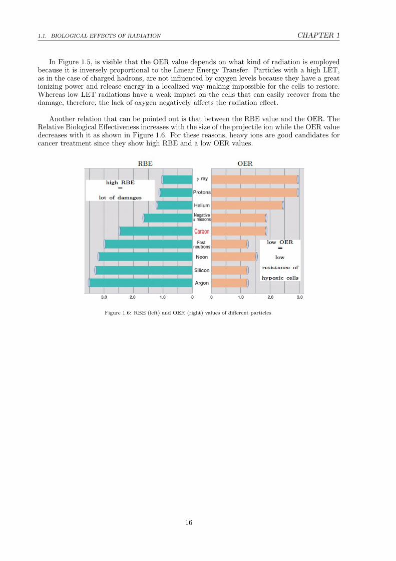
Another relation that can be pointed out is that between the RBE value and the OER. TheRelative Biological Effectiveness increases with the size of the projectile ion while the OER valuedecreases with it as shown in Figure 1.6. For these reasons, heavy ions are good candidates forcancer treatment since they show high RBE and a low OER values.
Figure 1.6: RBE (left) and OER (right) values of different particles.
16

CHAPTER 1 1.2. INTERACTION OF HEAVY CHARGED PARTICLES WITH MATTER
1.2 Interaction of Heavy Charged Particles with Matter
Heavy charged particles are really important in this discussion because they are the centralelement in the therapy with hadrons. In passing through a material, they undergo two differentprocesses: they can either lose energy or be deflected from their incident direction. Those areconsequences of the collisions with the atomic electrons or are caused by the elastic scatteringwith the nuclei of the atoms. Between these two electromagnetic processes, the first one domi-nates almost entirely the loss of energy because the probability of interaction, given by the crosssections, is σel = 1010σnucl. Another important process responsible for the particle energy lossis the nuclear fragmentation. All these processes will be explored in the next paragraphs.
1.2.1 The Bethe-Bloch formula and Stopping Power
1.2.1.1 Heavy Charged Ions
The energy loss rate is mainly ruled by inelastic collisions with target electrons. To betterformulate this mechanism, it is possible to apply some approximations; for example, if theparticle velocity is greater than the electron orbital velocity, the bound atomic electron can betreated as a free particle initially at rest. The momentum transfer can be assumed to be small,thus not causing the deflection of the particle trajectory and not inducing the recoiling electronto shift during the interaction. It is also necessary to neglect the particles magnetic interaction,since the electron is basically at rest. After these assumptions, the ionization process for unit ofpath length can be well described by the Bethe-Bloch formula:
−dEdx
= 2πNar2emec
2ρZ
A
z2
β2
[ln(2meγ
2v2Wmax
I2
)− 2β2 − δ − 2
C
Z
](1.5)
where:
2πNar2emec
2 ≈ 0.1535 MeV cm2/g
r2e classical electron radius = 2.817·10−13cm
me electron mass = 0.510998 MeV
Na Avogadro number = 6.022·1023
Z atomic number of absorbing material
A atomic weight of absorbing material
ρ density of absorbing material
z charge of incident particle
β v/c of the particle
γ 1√1−β2
Lorentz factor
Wmax maximum energy transfer in a single collision
I mean ionization potential
δ density correction
C shell correction
The quantity −dEdx is also called linear Stopping Power and describes the ratio of the differ-
ential energy loss to the corresponding differential traversed thickness.The formula 1.5 includes several correction terms due to the necessity of taking into account thequantum mechanical effects arising in dealing with light particles (z<10), such as protons. Acrucial term in the equation is I, the mean ionization energy of the material, since it rules theenergy loss of the projectile and its range.
17

1.2. INTERACTION OF HEAVY CHARGED PARTICLES WITH MATTER CHAPTER 1
At high energies, the density effect correction δ arises because the electric field of the incidentparticle tends to polarize the atoms along its path; as a consequence, the polarization shieldsouter electrons from the electric field, hence, collisions with these electrons account less to thetotal energy loss. This factor depends on the density of the crossed material because the inducedpolarization is greater when the material is denser.At low energies is the shell effect correction C/Z that becomes relevant; in fact, the electronin the target cannot be considered free anymore because the velocity of the incident particle iscomparable or smaller than the orbital velocity of the bound electron. In the low energy region,the incident particle tends also to pick up electrons along its path, lowering its effective chargeand stopping power.However, at the energies used in hadrontherapy, the terms δ and C are negligible.Lowering the energies even more, below ∼10 MeV/u, z has to be replaced by an effective chargeZeff because the ionization starts to interplay with the recombination process.
The energy loss rate increases as the particle slows down inside matter and reaches themaximum in correspondence of the Bragg-Peak, when the particle velocity is:
vp ∼ z2/3v0 (1.6)
where v0 = e2/h is the Bohr velocity. For 12C ions the the maximum occurs at a specificenergy of 350 keV/u. Beyond this point, in the last few µm of the particle path, the energydrops down to less than 10 keV/u and elastic collisions with target nuclei begin to contributesignificantly to the energy loss and dominate the stopping process. This is the Nuclear StoppingPower.
Figure 1.7: The stopping power as a function of the kinetic energy, for different particles. The minimum dEdx
value isapproximately the same for particles of same charge.
In Figure 1.7 the stopping power is plotted as a function of the particle’s energy. At non-relativistic velocities, dE
dx is dominated by the factor 1/β2, hence, it is inversely proportional tothe velocity. When v ∼ 0.96c, the stopping power reaches a minimum (similar for every chargedparticle); beyond this point 1/β2 becomes basically constant while dE
dx slowly rises because of thedependence on the logarithm of the Bethe-Bloch formula. Therefore, it is shown that a chargedparticle, crossing a medium, loses most of its energy at low kinetic energy values and that slowsdown with depth. Hence, there is a greater energy release, for unit of path length, at the end ofthe path rather than at the beginning. This behavior, shown in Figure 1.8, is described by thecharacteristic function named Bragg curve.
18

CHAPTER 1 1.2. INTERACTION OF HEAVY CHARGED PARTICLES WITH MATTER
Figure 1.8: Representation of a Bragg curve.
1.2.1.2 Electrons and Positrons
When considering electrons and positrons, the Bethe-Bloch formula has to be modified becausethese particles interact with orbital electrons that have the same mass. The total energy lossthey undergo is expressed as the sum of the loss of energy due to radiation’s emission and theloss of energy due to ionization:
−(dEdx
)tot
= −(dEdx
)rad−(dEdx
)ion
(1.7)
Coulombian interaction is the main process involved in the energy loss and its contributionis expressed by the ionization term in Formula 1.7).In addition, because of the small mass of these particles, another energy dissipation mechanismbecomes relevant: bremsstrahlung. It consists in the scattering of the particle in the nucleuselectric field (radiation term in Formula 1.7); it is negligible for low energies but becomes pre-dominant for energies of the order of some MeV. It also entails a great angular deviation thatdoes not occur with heavy ions.Moreover, the radiative energy loss is linear, hence, for a given energy value, it will exceed theionization energy loss that, instead, tends to acquire a constant value. The value in which thishappens is called critic energy EC :
−(dEdx
)rad
= −(dEdx
)ion
when E = EC (1.8)
1.2.2 Range
The distance that a particle travelling through a medium covers, before losing all its kineticenergy, is an important physical quantity called range. It is related to the characteristics ofthe tissue, particle type and energy. Its accurate estimation is relevant in performing precisionexposures of tumorous volumes reducing the damage to healthy tissues.The mean range is mathematically formulated as:
R(E0) =
∫ E0
0
(dEdx
)−1dE (1.9)
where dE/dx is the mean rate of energy loss and E0 is the energy of the incident particle. Itis calculated in the “Continuous Slowing Down Approximation” that assumes that the particlefollows a simplified straight path that does not take into account multiple Coulomb scattering.
19

1.2. INTERACTION OF HEAVY CHARGED PARTICLES WITH MATTER CHAPTER 1
This approximation is realistic and efficient for heavy charged particles since the effect of multiplescattering (Section 1.3.3) is generally small and the range corresponds to the position of theBragg peak.The slowing down process is not the same even for identical particles because the energy lossis affected by statistical fluctuations due to the large number of collisions. This means that thestopping point of the particle is distributed as a casual variable; this, in the case of heavy ions,generates the broadening of the Bragg peak as it is shown in Figure 1.9. Therefore, there is theeffect of range straggling, meaning that the values spread out in a Gaussian distribution centredon the mean range (Fig.1.10).
Figure 1.9: Example of Bragg curve vs penetration depth for an α particle with an initial energy of 7 MeV. Both singleparticle track and the average behaviour of a parallel beam of α particles of the same initial energy, are shown. The
difference between the two plots is due to the straggling effect.
Figure 1.10: Experimental representation of the Gaussian distribution of a beam of identical particles around the meanrange.
For heavy charged particles, this distribution approximation fails at large angles because isalso necessary to take into account the effect of nuclear interactions that generates a tail in thedistribution, behind the Bragg peak.
1.2.3 Multiple Scattering
The main process, that a charged particle crossing a medium undergoes, is the inelastic electro-magnetic interaction with electrons that causes energy loss by ionization. However, the particlecan also interact with the target nuclei elastically, in a process called multiple Coulomb scat-tering. It induces great angular deflections that have the overall effect of deviating the particle
20

CHAPTER 1 1.2. INTERACTION OF HEAVY CHARGED PARTICLES WITH MATTER
from the initial beam trajectory.In this diffusion process, the main mechanism of energy loss is that of bremsstrahlung that con-sists in the slowing down of the particle and the consequent emission of a photon, as depictedin Figure 1.11 .
Figure 1.11: Bremsstrahlung produced by an electron deflected in the electric field of an atomic nucleus.
1.2.4 Nuclear Fragmentation
Another important phenomenon to take into account in the stopping process of high energy ions(energy of the order of hundreds of MeV), in a tick absorber, is that of nuclear interactions (Fig.1.12).
Figure 1.12: Stopping power curves for protons and 12C ions in water. For protons, the inelastic collision with electrons isthe dominant process for all energies. For 12C ions the same process dominates almost all the dose release, except for the
last few micrometers of path where the nucleus-nucleus interactions become dominant.
Although less probable than multiple scattering, nuclear interactions lead to significant effectscausing the projectile or the target to fragment into lighter ions. In fact, when the energies arehigh enough, the projectile can overcome the coulombian barrier of target nuclei and interactdirectly with the nucleons.This fragmentation process influences significantly the released dose map, generating, in case
21

1.2. INTERACTION OF HEAVY CHARGED PARTICLES WITH MATTER CHAPTER 1
of projectile fragmentation, the characteristic tail beyond the Bragg peak that becomes morerelevant with increasing ion mass number A (Fig.1.13).
Figure 1.13: Differences in the relevance of the nuclear fragmentation process in the dose profile of protons and Carbonions. In proton irradiation the dose beyond the peak is really small, while in Carbon irradiation there is the formation of a
dose-release tail.
Nuclear interactions can be elastic or inelastic. If the incident particle undergoes an elasticinteraction the kinetic energy is conserved and this leads to an angular deviation of the projectile.When, on the other hand, an inelastic collision takes place, the produced effect is more relevantbecause the kinetic energy is not conserved and the interaction may result in the fragmentationof the incident particle and/or of the target nuclei. Consequently, this leads to a build-up oflighter and less charged fragments that are moving at about the same speed as the beam (Fig.1.14). The angular distribution of secondary fragments around the initial direction causes alsoa broadening of the lateral spreading of the deposited dose, therefore, inducing a deteriorationof the longitudinal and lateral dose profile (Fig. 1.15). The impact of this effect intensifies withdepth in the medium and beam energy.
Figure 1.14: Energy spectrum of secondary particles, Hydrogen (a) and Helium (b), produced in the fragmentation of a12C beam at 400 MeV/u in a water absorber 27.9 cm deep. Distinct curves correspond to different emission angles (0, 4
and 6 on the left and 0, 1, 2, 4, 6 on the right).
Is important to take into account the fragmentation process because, for instance, in a 40MeV/u C ions beam on water, 70% of the primary particles do not reach the Bragg peak,undergoing nuclear reactions. A more detailed explanation of this phenomenon will be given inChapter 3.
22

CHAPTER 1 1.2. INTERACTION OF HEAVY CHARGED PARTICLES WITH MATTER
Figure 1.15: Energy spectrum of secondary particles produced in the fragmentation of a 12C beam at 400 MeV/u in awater absorber. Curves correspond to an emission angle of 2 around the initial direction. Four different depth in thecharacteristic Bragg curve are considered: (a) entrance channel, (b) plateau region, (c) Bragg peak, (d) distal edge.
23
1.3. APPLICATION IN CANCER TREATMENT CHAPTER 1
1.3 Application in Cancer Treatment
1.3.1 Radiotherapy
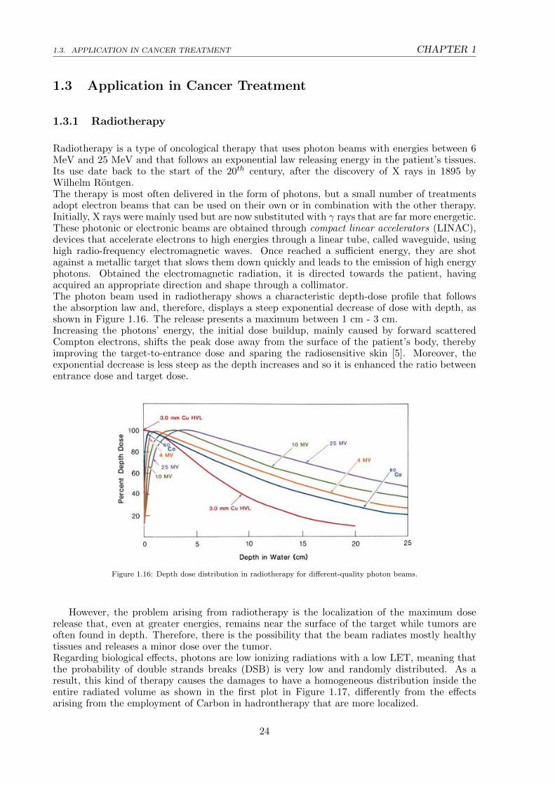
Radiotherapy is a type of oncological therapy that uses photon beams with energies between 6MeV and 25 MeV and that follows an exponential law releasing energy in the patient’s tissues.Its use date back to the start of the 20th century, after the discovery of X rays in 1895 byWilhelm Rontgen.The therapy is most often delivered in the form of photons, but a small number of treatmentsadopt electron beams that can be used on their own or in combination with the other therapy.Initially, X rays were mainly used but are now substituted with γ rays that are far more energetic.These photonic or electronic beams are obtained through compact linear accelerators (LINAC),devices that accelerate electrons to high energies through a linear tube, called waveguide, usinghigh radio-frequency electromagnetic waves. Once reached a sufficient energy, they are shotagainst a metallic target that slows them down quickly and leads to the emission of high energyphotons. Obtained the electromagnetic radiation, it is directed towards the patient, havingacquired an appropriate direction and shape through a collimator.The photon beam used in radiotherapy shows a characteristic depth-dose profile that followsthe absorption law and, therefore, displays a steep exponential decrease of dose with depth, asshown in Figure 1.16. The release presents a maximum between 1 cm - 3 cm.Increasing the photons’ energy, the initial dose buildup, mainly caused by forward scatteredCompton electrons, shifts the peak dose away from the surface of the patient’s body, therebyimproving the target-to-entrance dose and sparing the radiosensitive skin [5]. Moreover, theexponential decrease is less steep as the depth increases and so it is enhanced the ratio betweenentrance dose and target dose.
Figure 1.16: Depth dose distribution in radiotherapy for different-quality photon beams.
However, the problem arising from radiotherapy is the localization of the maximum doserelease that, even at greater energies, remains near the surface of the target while tumors areoften found in depth. Therefore, there is the possibility that the beam radiates mostly healthytissues and releases a minor dose over the tumor.Regarding biological effects, photons are low ionizing radiations with a low LET, meaning thatthe probability of double strands breaks (DSB) is very low and randomly distributed. As aresult, this kind of therapy causes the damages to have a homogeneous distribution inside theentire radiated volume as shown in the first plot in Figure 1.17, differently from the effectsarising from the employment of Carbon in hadrontherapy that are more localized.
24

CHAPTER 1 1.3. APPLICATION IN CANCER TREATMENT
Figure 1.17: Microscopical dose distribution for different radiations. The average dose is 2 Gy.
25
1.3. APPLICATION IN CANCER TREATMENT CHAPTER 1
1.3.2 Hadrontherapy
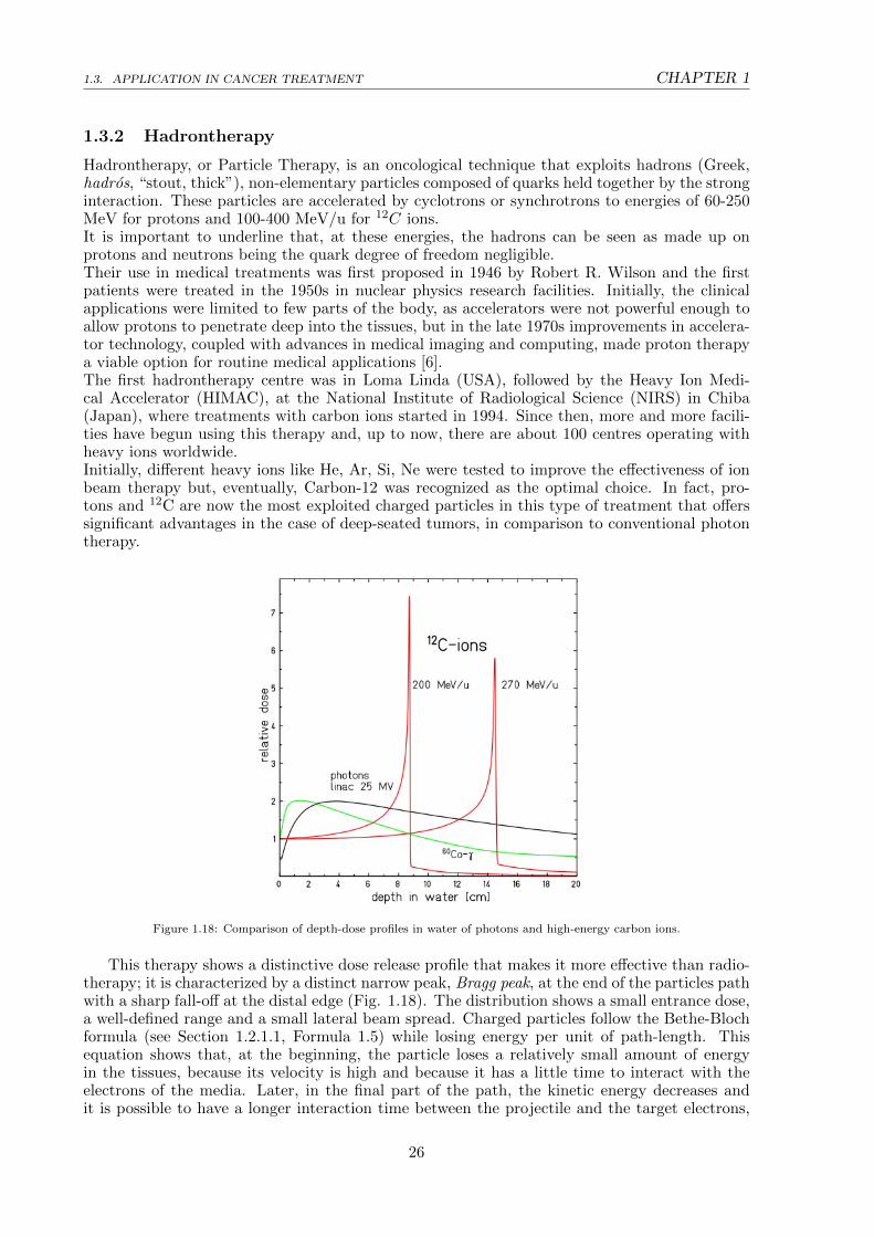
Hadrontherapy, or Particle Therapy, is an oncological technique that exploits hadrons (Greek,hadros, “stout, thick”), non-elementary particles composed of quarks held together by the stronginteraction. These particles are accelerated by cyclotrons or synchrotrons to energies of 60-250MeV for protons and 100-400 MeV/u for 12C ions.It is important to underline that, at these energies, the hadrons can be seen as made up onprotons and neutrons being the quark degree of freedom negligible.Their use in medical treatments was first proposed in 1946 by Robert R. Wilson and the firstpatients were treated in the 1950s in nuclear physics research facilities. Initially, the clinicalapplications were limited to few parts of the body, as accelerators were not powerful enough toallow protons to penetrate deep into the tissues, but in the late 1970s improvements in accelera-tor technology, coupled with advances in medical imaging and computing, made proton therapya viable option for routine medical applications [6].The first hadrontherapy centre was in Loma Linda (USA), followed by the Heavy Ion Medi-cal Accelerator (HIMAC), at the National Institute of Radiological Science (NIRS) in Chiba(Japan), where treatments with carbon ions started in 1994. Since then, more and more facili-ties have begun using this therapy and, up to now, there are about 100 centres operating withheavy ions worldwide.Initially, different heavy ions like He, Ar, Si, Ne were tested to improve the effectiveness of ionbeam therapy but, eventually, Carbon-12 was recognized as the optimal choice. In fact, pro-tons and 12C are now the most exploited charged particles in this type of treatment that offerssignificant advantages in the case of deep-seated tumors, in comparison to conventional photontherapy.
Figure 1.18: Comparison of depth-dose profiles in water of photons and high-energy carbon ions.
This therapy shows a distinctive dose release profile that makes it more effective than radio-therapy; it is characterized by a distinct narrow peak, Bragg peak, at the end of the particles pathwith a sharp fall-off at the distal edge (Fig. 1.18). The distribution shows a small entrance dose,a well-defined range and a small lateral beam spread. Charged particles follow the Bethe-Blochformula (see Section 1.2.1.1, Formula 1.5) while losing energy per unit of path-length. Thisequation shows that, at the beginning, the particle loses a relatively small amount of energyin the tissues, because its velocity is high and because it has a little time to interact with theelectrons of the media. Later, in the final part of the path, the kinetic energy decreases andit is possible to have a longer interaction time between the projectile and the target electrons,
26
CHAPTER 1 1.3. APPLICATION IN CANCER TREATMENT
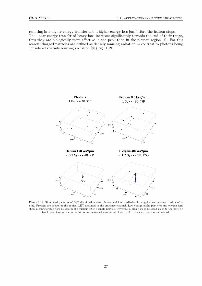
resulting in a higher energy transfer and a higher energy loss just before the hadron stops.The linear energy transfer of heavy ions increases significantly towards the end of their range,thus they are biologically more effective in the peak than in the plateau region [7]. For thisreason, charged particles are defined as densely ionizing radiation in contrast to photons beingconsidered sparsely ionizing radiation [8] (Fig. 1.19).
Figure 1.19: Simulated patterns of DSB distribution after photon and ion irradiation in a typical cell nucleus (radius of ≈µm). Protons are shown at the typical LET assumed in the entrance channel. Low energy alpha particles and oxygen ionsshow a considerable dose release in the nucleus after a single particle traversal; a high dose is released close to the particle
track, resulting in the induction of an increased number of close-by DSB (densely ionizing radiation).
27

1.3. APPLICATION IN CANCER TREATMENT CHAPTER 1
The peak’s width depends on longitudinal and lateral energy dispersion of the beam andon the amount of matter crossed. For instance, the carbon peak is narrower than protons’ onebecause heavier ions are less influenced by multiple scattering.In addition, the position of the peak can be adjusted to the desired depth in tissue by changingthe kinetic energy of the incident ions (initial beam parameters) (Fig. 1.20 - Fig. 1.21).
Figure 1.20: 12C beams attenuation in water (upper plot) and corresponding Bragg peaks (lower plot).
Figure 1.21: Bragg peak position for different kinetic energies.
Protons and carbon ions, despite being both employed in the therapy, have different featuresfor what concerns the biological effects and the dose tail. Protons have a similar biologicalresponse to photons, considering the same absorbed dose, while heavy ions show higher effec-tiveness. In addition, heavy ions, unlike protons, exhibit a distinctive dose tail beyond the Braggpeak, caused by secondary fragments produced in nuclear reactions along the stopping path ofthe ions, resulting in a non-negligible amount of dose deposited in healthy tissues located beyondthe tumor.
28

CHAPTER 1 1.3. APPLICATION IN CANCER TREATMENT
Hadrontherapy of deep-seated tumors requires ion beams with great ranges in tissue that canreach depths up to 30 cm. They need specific energies that go up to 220 MeV/u (MeV pernucleon) for protons and helium ions and up to 430 MeV/u for carbon ions.
1.3.2.1 Spread Out Bragg Peak
A custom practice, in the clinical application of hadrontherapy, is the superimposition of differention beams with different energies, hence, various penetration distances in the patient body. Itis essential since the width of the Bragg peak is too narrow to cover all the tumour volume. Inorder to obtain a broader irradiation profile, this technique is applied and an extended Braggpeak is achieved. It is called Spread Out Bragg Peak (SOBP) and it is displayed in Figure 1.22.
Figure 1.22: Dose profile as a function of depth for a proton mono-energetic beam (red line). From the overlapping ofdifferent energy proton beams (black lines), the SOBP is obtained (blue line).
29

1.4. PROTON RBE CHAPTER 1
1.4 Proton RBE
Among all the charged particles of which hadrontherapy makes use, protons are one of themost employed. Despite the fact that nowadays proton therapy is a common technique to treatneoplastic diseases, there is still a lot to study about the biological response of the tissues. Sincethe beginning, the dose specification in proton radiation therapy has been based upon a genericRBE, a single value that is applied to all proton beam treatments independently of dose/fraction,position in the Spread Out Bragg Peak (SOBP), initial beam energy or the particular tissue.The value was assumed to be 1.1 along all range, but it’s important to consider fragmentationprocesses when studying proton therapy in order to develop a much more effective weightedRBE. When the incident beam interacts with the target in an inelastic-type collision, a non-negligible amount of fragments is produced outside of the planned area. They can derive fromthe target or from the projectile disintegration, according to the different conditions in whichthe fragmentation takes places (see Chapter 3, Section 3.2). Moreover, both these processes areassociated with different produced fragments behaviours.In the case of a proton beam the one to fragment is the target and the contribution due tonuclear interactions might be especially relevant in the entrance region (Fig. 1.23). Sincesecondary particles are expected to have high RBE values because of their small ranges, thiscould result in a variable RBE that can lead to an alteration in local dose deposition and anunder or overestimation of RBE along the path.
Figure 1.23: Cell killing caused by ionization or target fragmentation in tissue sections of 1 mm2. Red dots represent cellskilled by nuclear fragments interaction, while green dots are the cells killed by electron inelastic scattering.
This is apparent in Figure 1.23 which shows that the ratio, in the entry channel, betweenthe damage induced by fragmentation (red dots) and the one caused by ionization (green dots)is 1/8. In correspondence of the peak, on the other hand, the ratio drastically reduces to 1/40.Concerning heavy ions, the projectile fragments are mainly produced in the forward directioncausing the delivery of harmful radiation to tissues beyond the Bragg peak (Fig. 1.24).Therefore, the fragments play an important role in spreading collateral damage to the healthytissues crossed by the incident particles. Chapter 3 will examine in depth this collision productsand it will be shown that since the fragments have higher range and different directions, theycannot be neglected in treatment planning and that is extremely important to improve knowledgeof this effect in the energy range relevant for hadrontherapy.
30

CHAPTER 1 1.4. PROTON RBE
Figure 1.24: Dose release as a depth function for a 12C beam at 400 MeV/u, on water. Contributions from incident beamparticles (red line) and secondary fragments (black line) are shown.
The importance of a precise RBE in clinical treatment can be understood by looking atFigure 1.25: the distal end of the curve presents a delayed fall off in the case of a weighted RBEunlike with a constant RBE value. This means that neglecting the RBE variability may lead tothe exposure of organs at risk (OARs) located behind the tumor. Therefore, a proper knowledgeof this biological difference is very much needed.
Figure 1.25: Distal fall off in the case of a weighted RBE and of a constant RBE.
31

32

Chapter 2
The FOOT Experiment
An open question in hadrontherapy concerns the lack of experimental results on the nuclearfragmentation due to the interaction of the incident beam with the human tissue. For thispurpose, the FOOT (FragmentatiOn Of Target) experiment was developed to measure thesefragmentation cross sections. The knowledge of these data will help provide a better under-standing of nuclear interactions between the beam and the patient tissues during the therapyand will enhance the accuracy of the treatment plan thanks to the calculations of the fragmentsdistributions obtained from cross sections. In fact, the target fragmentation generates a spec-trum of low energy, heavy fragments that are one of the causes behind the variability of protonRBE (see Section 1.4).
The FOOT experiment is a project supported by INFN and implemented with the collab-oration of the Italian laboratories of CNAO (National Centre of Oncological Hadrontherapy),sited in Pavia, and TIFPA (Trento Institute for Fundamentals Physics Applications), along withother international institutions like the GSI (Gesellschaft fur Schwerionenforschung) center andHIT (Heidelberg Ion-Beam Therapy Center) in Germany.
The data taking will take place using beams of protons, Carbon and Oxygen in the 150-400MeV/u energy range and with the appropriate resolution for the hadrontherapy treatment. Tothis end, possible candidate sites for the experimental application, equipped with beams thatsatisfy the mentioned requirements, are the experimental halls of CNAO, HIT, GSI and TIPFA(for the calibration phase).The need to fit the space limitations set by the different experimental and treatment rooms,has shaped the design of the apparatus that has to be easily movable - table top setup – andmust have a length of about 2 m along the beam line while still covering the fragments angularspread.Test beam data taking have been performed since 2017, while physical runs are foreseen for theend of 2020 and for all 2021.
This Chapter will cover, in Section 2.1, the purposes of the FOOT experiment concerningthe influence of the target fragmentation in the RBE evaluation, the fragmentation of Carbon,Oxygen and Helium beams and the possibility of employing the experimental setup to gaindata useful for the radioprotection in space missions. Moving on, section 2.2 will provide adetailed description of the experimental setup focusing on the two different setups implementedfor the detection of heavy charged particles (electronic setup) and light fragments (emulsionspectrometer). In section 2.3 will be listed the goals set for FOOT and the experimental re-quirements. Moreover, section 2.4 will conclude showing the measurements that are required forthe fragments identification.
33

2.1. THE AIM OF THE EXPERIMENT CHAPTER 2
2.1 The aim of the experiment
2.1.1 Target fragmentation and RBE variability
The FOOT experiment was proposed to fix the lack of measurements of the nuclear cross sectiondata for the production of heavy recoils after proton and Carbon irradiation in the energy rangeof interest, up to 250 MeV and 400 MeV/u, respectively.At the moment, the biological effectiveness does not take into account all the possible nuclearinteractions between the beam ions and the nuclei of the human body that can cause variousside effects.This study of nuclear fragments spectra has a great importance in the search for accuratetreatment planning systems (TPS) that aim at accounting as much as possible the biologicaleffects arising from the fragments irradiation of tissues. The goal is to obtain a highly accuratedescription of the relative biological effectiveness (RBE-weighted) to supply the adequate dose.Other experiments have directed their research towards the study of projectile fragmentation,due to nuclear interaction, for different types of ions and, in particular, for 12C, but the energyrange addressed is still narrow [9,10]. In addition, until now, the process of target fragmentationhas been almost completely neglected despite is importance, hence, the challenge will be thecharacterization of target fragment production cross sections for proton beams.FOOT will also provide data for the fragmentation of high LET ions like Carbon, Oxygen andHelium beams.
2.1.2 Projectile fragmentation for Carbon beams
Carbon nuclei have an important role in cancer therapy motivated by their therapeutic advan-tages over proton beams as a very precise high LET radiation [11].The knowledge of their fragmentation in the interaction with the human body is important toevaluate the spatial profile of the deposited dose and the damage to the tissues neighbouringthe tumour.
2.1.3 Projectile fragmentation for Oxygen beams
In the last chapter was underlined the importance of the presence of Oxygen in cancerous tissuein promoting the biological effectiveness of radiations. To this end, Oxygen beams have startedbeen considered as an effective tool against hypoxic tumours [12]. They are selected for theirfeatures similar to those of Carbon ions, but, most importantly, for their high LET value that, asalready established, is associated with a low OER. However, in normal conditions, these beamsshow a larger fragmentation in the target and entrance channel, making their use less convenientas compared to lighter ions, such as C, producing a worse peak-to entrance ratio.
2.1.4 Projectile fragmentation for Helium beams
The FOOT experiment will also focus is attention on Helium beams because they seem to be apromising alternative to protons and higher LET ions [13]. The advantage of introducing Heliumions over protons consists in the lower impact of multiple Coulomb scattering that allows a higherresolution in close lateral proximity of organs at risk (Fig. 2.1) [14]. Moreover, compared toCarbon ions, these beams have a much lower impact of nuclear fragmentation in critical regionslike the tail after the peak. In conclusion, Helium has an increased biological effectiveness inthe target and a more affordable implementation cost that makes it an optimal candidate formedical therapy.
34

CHAPTER 2 2.1. THE AIM OF THE EXPERIMENT
Figure 2.1: Comparison of treatment plans, on a skull cancer, showing the little lateral diffusion of Helium ions, muchmore convenient as compared to protons and Carbon ions.
2.1.5 Radioprotection in Space
The measurements performed by FOOT are not only suitable for therapeutic purposes but forother applications too, like radioprotection in space [15]. With the same experimental methodit is possible to assess the risk for astronauts in perspective of long duration space missions forwhat concerns the radiation sources that can be found in space. It is important to quantify theradiation field within the vessel and, thus, the cumulative dose received by the human inside.However, knowing accurately the composition and energy spectrum of space radiation parti-cles is not sufficient because the radiation outside the spacecraft is modified by the interactionwith its walls and its shielding material. Therefore, atomic and nuclear interactions occurringbetween the incoming particles and the material of the vessel need to be characterized. Withfragmentation process data is possible to design and optimize the spacecraft shielding in orderto consider lighter fragments with a higher penetrating power. This study is really importantbecause some of these radiations have the capacity of inflicting a lethal dose to the astronautsas in the case of protons emitted from the sun during coronal mass ejections and solar flares(SPEs – Solar Particle Events). Other harms could arrive from Galactic Cosmic Rays (GCR)and geomagnetically trapped particles that are considered to be among the most significanthazards for humans in space. Typical energies are of the order of GeV and can be measured byFOOT.
Despite the differences, there is a common ground between pursuing radioprotection againstthe harmful effects of space radiation and providing tumor therapy to patients using ions. Infact, the particle species of interest to medical therapy, such as protons, Carbon ions, Heliumand Oxygen are among the most abundant in space, as well. In addition, the energy range fortumor therapy is not far from the typical energies of space particles that, on average, can reachvalues in the GeV range. In addition, as in the case of therapy-oriented analysis, measurementson hydrogen targets will be required also for radioprotection, because hydrogen-rich materialsare among the best shielding options. Therefore, these shared interests allow the interchange ofcross sections data. FOOT will carry out measurements of the fragmentation cross section ofH, 4He and 12C beams with kinetic energy extended up to 1 GeV/u with the main focus of Zidentification.
35
2.2. THE EXPERIMENTAL SETUP CHAPTER 2
2.2 The experimental setup
The design of the setup is driven by the necessity of detecting very short range (order of tens ofmicrons) and very low energy (few MeV) fragments produced by the target fragmentation due tothe interaction with the proton beam. It is necessary to take advantage of an inverse kinematicsapproach that switches the roles of projectile and target in order to have secondary fragmentswith boosted velocity and a dose deposition outside the planned target region. Therefore, FOOTwill study the fragmentation of different ions beams (C, O, . . . ) onto hydrogen-enriched targetwhere secondary fragments have more energy and a much longer range, making their detectioneasier. Chapter 3 will focus entirely on this fundamental technique.
Another major point to take into consideration when designing the apparatus, it is thatthe setup has to be built so that is assured a good balance between the production cost, theportability and the necessity for the largest possible geometrical acceptance for the fragments.The setup will analyze the produced fragments and obtain their trajectory, momentum, kineticenergy, Time Of Flight (TOF) and dE
dx .
The first region that the incident beam encounters, in its path inside the apparatus, is repre-sented by the upstream region. This has an important role in the experiment because provides acounter for the rate of the ion beam, the trigger signal to start the TOF measurement and a trackof the beam position and direction. All these data are fundamental for the application of theinverse kinematics that uses the Lorentz transformation in order to switch back, mathematicallyspeaking, projectile and target that, otherwise, are inverted in the actual setup.
2.2.1 Start Counter
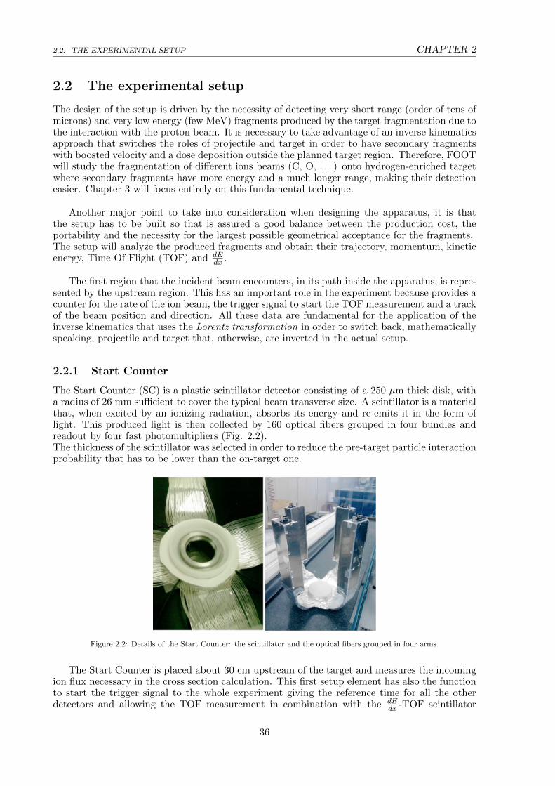
The Start Counter (SC) is a plastic scintillator detector consisting of a 250 µm thick disk, witha radius of 26 mm sufficient to cover the typical beam transverse size. A scintillator is a materialthat, when excited by an ionizing radiation, absorbs its energy and re-emits it in the form oflight. This produced light is then collected by 160 optical fibers grouped in four bundles andreadout by four fast photomultipliers (Fig. 2.2).The thickness of the scintillator was selected in order to reduce the pre-target particle interactionprobability that has to be lower than the on-target one.
Figure 2.2: Details of the Start Counter: the scintillator and the optical fibers grouped in four arms.
The Start Counter is placed about 30 cm upstream of the target and measures the incomingion flux necessary in the cross section calculation. This first setup element has also the functionto start the trigger signal to the whole experiment giving the reference time for all the otherdetectors and allowing the TOF measurement in combination with the dE
dx -TOF scintillator
36
CHAPTER 2 2.2. THE EXPERIMENTAL SETUP
detector. In the case of Carbon ions at 400 MeV/u, it is possible to reach a time resolution of70 ps.
2.2.2 Beam Monitor
The Beam Monitor (BM) is a drift chamber detector employed to measure the space coordinatesof the trajectory of a charged particle (Fig. 2.4). The detection of the particle signal can bedivided in three stages.The first mechanism that takes place is the ionization process during which charged particlesionize the gas colliding with one of the atoms and producing an electron-ion pair. Particlescrossing matter lose energy following the Bethe-Bloch theory and can be detected analyzing thehomogeneously distributed ionization clusters that they leave behind. It is possible for extractedelectrons to cause secondary ionizations that induce a signal in the drift chamber and leads tobackground events.The second stage of the particle tracking is the transport phase. The electron-ion pairs, previ-ously generated, are subjected to the effect of an electric field and of thermal diffusion that causethe migration of pairs towards the electrodes of opposite polarity. Moreover, in this process,the particles are subjected to multiple collisions with the gas molecules. It is possible to definea macroscopic average velocity, drift velocity, which characterizes such migration processes. Incase of a constant electric field, the inelastic collisions randomize the particles trajectory leadingto a constant velocity that allows to track down the position of initial ionization exploiting thedrift time interval.The last process is the multiplication cascade that starts when the electrons approach the elec-trodes. The strong electric field increases their velocity and induces a great amount of ionizationsthat generates an ”avalanche”. This electron avalanche generates a fast current pulse that islater digitized and read. It allows to reconstruct the coordinate along the drift direction byconsidering the time difference with respect to a trigger signal.
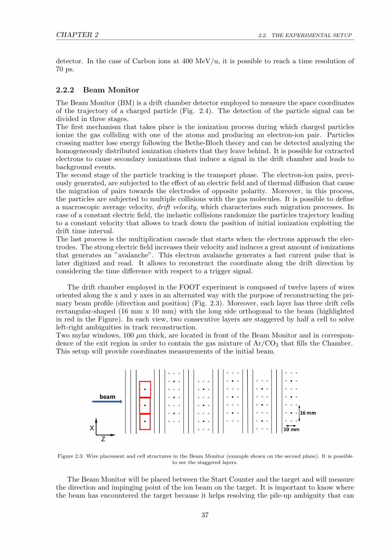
The drift chamber employed in the FOOT experiment is composed of twelve layers of wiresoriented along the x and y axes in an alternated way with the purpose of reconstructing the pri-mary beam profile (direction and position) (Fig. 2.3). Moreover, each layer has three drift cellsrectangular-shaped (16 mm x 10 mm) with the long side orthogonal to the beam (highlightedin red in the Figure). In each view, two consecutive layers are staggered by half a cell to solveleft-right ambiguities in track reconstruction.Two mylar windows, 100 µm thick, are located in front of the Beam Monitor and in correspon-dence of the exit region in order to contain the gas mixture of Ar/CO2 that fills the Chamber.This setup will provide coordinates measurements of the initial beam.
Figure 2.3: Wire placement and cell structures in the Beam Monitor (example shown on the second plane). It is possibleto see the staggered layers.
The Beam Monitor will be placed between the Start Counter and the target and will measurethe direction and impinging point of the ion beam on the target. It is important to know wherethe beam has encountered the target because it helps resolving the pile-up ambiguity that can
37
2.2. THE EXPERIMENTAL SETUP CHAPTER 2
appear in the following vertex detector (VTX). In fact, if there is a good alignment between BMand VTX, the positions of the vertices reconstructed by the VTX for each event can be comparedwith the position of the BM track, and only the closest vertex to the BM extrapolation is selectedas a matching vertex. Thanks to the fast read-out time (order of 1 s or less), compared to theVTX read-out time (=187 µs), the BM can ensure that tracks belonging to different eventscannot be mixed.Another purpose of the BM is to reject the events in which the primary beam undergoes anuclear inelastic interaction before the target.
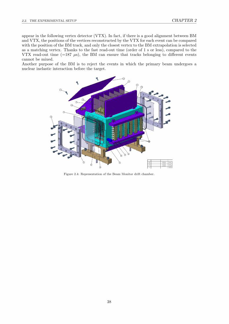
Figure 2.4: Representation of the Beam Monitor drift chamber.
38

CHAPTER 2 2.2. THE EXPERIMENTAL SETUP
2.2.3 Fragments detection setup
Studying previous nuclear fragmentation experiments and analyzing models elaborated throughMontecarlo simulations it is clear that is not possible to detect all secondary fragments with anapparatus of limited size. Lower mass fragments (Z ≤ 2), such as protons and deuterons, in fact,display a wider emission angle than that of heavier nuclei that, instead, are ejected in a forwarddirection. Therefore, the setup needs to be extended in order to appreciate both kind of ions;however, the necessary size and weight of an apparatus capable of doing this, would becomeimpracticable considering the spatial limitations already mentioned. To solve this problem, theFOOT experiment will implement two different setups for the two fragments mass intervals.
Heavier fragments (Z > 2) will be detected with a setup covering an angular acceptance of10 (Fig. 2.5), with respect to the beam axis, while lighter particles will be revealed with anemulsion chamber capable of extending the angular acceptance up to about 70.
Detection of Heavy charged particles
Figure 2.5: Schematic view of the FOOT apparatus for heavy particles.
2.2.3.1 Target
After the Start Counter and the Beam Monitor, the target can be found. It is composed of twolayers of polyethylene C2H4 and carbon C, respectively, thanks to which it is possible to performmeasurements of the proton cross section that is obtained from the subtraction of the two layerscross sections, as will be thoroughly discussed in Chapter 3.The thickness of the target is chosen to be about 2 mm in order to prevent the possibility of
39

2.2. THE EXPERIMENTAL SETUP CHAPTER 2
trapping the fragments, as would happen with a thicker target, but to also avoid the excessivedrop in the interaction rate that, on the contrary, happens when employing a thin target.
2.2.3.2 Magnetic Spectrometer
The magnetic spectrometer represents the tracking system of FOOT. It is arranged in threemeasuring stations: two upstream stations of monolithic pixel sensors and a telescope of siliconmicrostrip detectors for the downstream station. In between, two permanent magnets providethe required field and perform the function of bending the fragments produced in the target.
A magnetic spectrometer is an apparatus composed of a magnet that produces a magneticfield B and one or more detectors designated to track the particle trajectory. Thanks to the
Lorentz force (~FB = q~v × ~B , where q is the charge, ~v is the particle velocity and ~B is themagnetic field), particles are deflected from the incident beam direction and knowing the radiusof curvature (r) is possible to deduce the particles momentum. In fact, since the velocity of thebeam is perpendicular to the magnetic field B, the momentum is defined as p = rqB.
Vertex Pixel Tracker (VTX) Immediately after the target, is placed a telescope of pixeltrackers providing the vertex reconstruction and the initial tracking of the produced fragments.There are four layers of silicon detectors (Fig. 2.6) arranged in such a way that an accep-tance level of about ± 40 degrees is guaranteed for the fragments produced in the target. Eachsensor layer consists of a matrix composed by 928 (rows) × 960 (columns) pixels with a sidelength of 20.7 µm meaning an overall size of the chip of 20.22 mm × 22.71 mm. Every sensorshave a reduced thickness of 50 µm in order to minimize the multiple scattering and nucleusre-fragmentation like in the Vertex. The sensors will be arranged in two sub-stations separatedby a gap of about 10 mm and will consist of two sensors each at a distance of 3 mm to oneanother.This setup will ensure a reconstruction efficiency of about 95% (excluding the geometrical ac-ceptance); the measured cluster position resolution is better than 10 µm and the vertex spatialresolution is 10 µm in the plane orthogonal to the beam direction and 60 µm along the beamdirection.
Figure 2.6: Target (green) and vertex tracker (brown) geometrical scheme.
Permanent Magnet The setup involves the use of two permanent magnets with Halbachgeometry meaning that the dipolar magnetic field is obtained with magnets of cylindrical shapewhere the internal cylindrical hole presents a rather uniform magnetic field of 0.8 T (Fig. 2.7).The magnets are arranged to leave a central aperture of 4.5 cm in radius and are made of twelve
40

CHAPTER 2 2.2. THE EXPERIMENTAL SETUP
single pieces of SmCo (Samarium-Cobalt) or NeFeB (Neodymium-Iron-Boron) (with a width of10 cm). It is important to choose wisely the material, dimensions and thickness of the magnetsbecause they affect the produced field and contribute to the achievable strength. Simulationshave shown that the required level of performances can be achieved with a total weight and sizethat is compatible with the inspiring concept of portability.
Figure 2.7: Halbach configuration for the double magnet design.
Figure 2.8: Magnetic field amplitude (Gauss) along the axis of the two magnets system. A not uniform magnetic field isapproximated by the convolution of two Gaussian distributions each relative to a single magnet.
Inner Tracker Station Between the two magnets there is the second silicon pixel trackerthat consists of two planes of pixel sensors to improve the trajectory and momentum measure-ment. Inside the two layers is placed a 2 mm thick plate of SiC (a low density foam) as a spacer.Therefore, this detector has the same structure of the VTX but covers a larger area of about 8cm x 8 cm.In the region occupied by the inner tracker the residual magnetic field is not negligible (∼ 0.6T)(Fig. 2.8) but the sensor outcomes should not be significantly affected. The only flaw is that theperformances will be slightly influenced by the mechanical arrangement that needs some morematerial to hold the sensors, now covering a larger area, and to fix the distances between thetwo planes. The cost will also increase due to the need for more material.
Outer Tracker The last tracker downstream the magnetic volumes is a Microstrip SiliconDetector (MSD). It is used to perform a global tracking with the other silicon detectors and tomatch the reconstructed tracks with the hits in the TOF scintillator and the calorimeter. It
41

2.2. THE EXPERIMENTAL SETUP CHAPTER 2
will also provide a redundant measurement of dEdx that is relevant for the improvement of the
reliability of the experiment.
The Microstrip Silicon Detector covers an area of 9 × 9 cm2 according to the 10 openingangle needed to detect heavy ions. Each component microstrip is as long as the entire detector.It is a p-n junction tracking detector (Ionization Detector) where the electron-hole pairs, pro-duced by the incident particle, are collected in the electrodes. This induced current generates asignal that is later amplified thanks to a Low Gain Avalanche Diode (LGAD). From the obtainedsignal is possible to reconstruct the fragments trajectory inside the detector.
A benefit of this kind of detector is that it requires a reduced amount of material meaningthat the impact of multiple scattering and of secondary fragmentation is minimized.It is made of three x-y planes with a 2 cm gap between them, along the beam direction. Eachplane has a thickness of about 150 µm obtained by two silicon planes of 70 µm glued togetherusing a 30 µm thick bi-adhesive giving an equivalent silicon thickness of ∼ 155 µm.The MSD allows to achieve stopping power measurements with high level precision, in a widekinetic energy range, useful for hadrontherapy and radioprotection in space studies.
2.2.3.3 Identification Region
Scintillator Downstream the magnetic spectrometer region, there is a Plastic Scintillatorwith the task of providing the stop to the TOF measurement, began in the Start Counter, andto measure the energy release in a thin slab of plastic scintillator, dE
dx , to identity the charge ofthe crossing fragment.Scintillators are detectors that exploit the light (photons) emitted by an ionized atom in thetransition between an excited state and the fundamental level.In this specific case, it is made of two orthogonal layers of 20 plastic (polystyrene) scintillatorbars, each 2 cm large and 40 cm long. These dimensions are suitable to achieve a coverage of theangular distribution of the fragments 1 m far from the target. With optical glue, the scintillatorbars are coupled, at both ends, to silicon photomultipliers that detect the light signal (photons),generated during ionization and collected by the rods, transforming it in an amplified electronicsignal. The orthogonal arrangement is intended to identify the two-dimensional interactionposition of the particle in the detector. Moreover, the spatial resolution in the two directions isgiven by the bar section, 20 mm, which matches the calorimeter pixel size. Each scintillator rodhas a thickness of 3 mm (6 mm for the double FOOT layer) that is a compromise between thesearch for an improved resolution of dEdx and TOF and the necessity of reducing re-fragmentation.
Calorimeter The Calorimeter is positioned at a distance of about 100 cm from the targetand has the task of measuring the energy of the produced fragments.The fragments that reach the Calorimeter need to have a high enough energy to prompt a showerof photons and, therefore, to generate a proportional signal.The chosen material is a dense crystal like BGO (bismuth germanate). The calorimeter needsto cover a circular surface with a radius of about 20 cm, dictated by the emission angle of theheavy fragments, meaning that about 350 individual BGO crystals with 2 × 2 cm2 transversesize will be used. This crystals granularity is requested to keep the events with multiple frag-ments impinging in one crystal below the percent level.The overall crystal thickness is about 24 cm to allow containing fragments of the already dis-cussed energy range.
An open question is represented by the energy not recovered after the nuclear interactionof the fragments with the calorimeter material, due to the neutrons production. Typically,these produced neutrons travel for an unpredictable length before undergoing any other inter-action and have a non-zero probability to escape from the calorimeter leading to a systematicunderestimation of the kinetic energy of the fragments.
42

CHAPTER 2 2.2. THE EXPERIMENTAL SETUP
Detection of Light charged particles
The study of low Z fragments requires the use of an Emulsion Spectrometer (ES) differentlyfrom the electronic setup employed for heavier particles. The apparatus will be positioned rightafter the Start Counter and the Beam Monitor. It takes advantage of nuclear emulsions and itis very effective in achieving the highest spatial resolution when tracking ionizing particles orshort-lived particles.In this setup, target and detector are integrated in the compact arrangement of the emulsionchamber that can provide an accurate reconstruction of the interactions occurring inside thetarget (Fig. 2.9). The emulsion setup requires neither power supply nor readout electronics.
Figure 2.9: Schematic view of the FOOT apparatus for light particles.
The chamber is made of alternating passive materials, as Carbon and Lead, and nuclearemulsions films acting as both high-resolution tracking devices and ionization detectors. Eachnuclear emulsion film can be divided in two sensitive layers, 50 µm thick, that are made of AgBr(Silver bromide) crystals dispersed in a gelatin binder. These layers are then deposited on thesides of a 200 µm plastic base, resulting in a total thickness of 300 µm. The crystals in thereactive layers record the particle trajectory and through the chemical process of development,grains are grown around the latent image centers and become visible through an optical micro-scope. Scanning the emulsion and then analyzing the acquired image, it is possible to associatedark pixels to the grains and to reconstruct the track of the penetrating particle recognizingclusters of aligned pixels.Analyzing the grain density along the particle track it is possible to evaluate the fragmentcharge with a high efficiency (above 99%) while various elements are discerned comparing thetrack length of the detected particles.
The emulsion chamber will be divided in three sections (visible in Figure 2.10): vertexand tracking detector, ionization detector for charge identification and tracking detector formomentum measurements.
43

2.2. THE EXPERIMENTAL SETUP CHAPTER 2
Figure 2.10: Scheme of the Emulsion Spectrometer composition.
Vertex and Tracking Detector The first section of the emulsion chamber (Fig. 2.10)will be made of Carbon or C2H4 layers (1 mm) cells, that work as targets, and emulsion films(300 µm) (Fig. 2.11). These layers will interact with the incident beam, originating secondaryfragments that will be tracked by the detector and used to reconstruct the interaction vertexposition. It is important to achieve a significant number of reactions in this section, hence, afteran accurate event probability estimation, the length needed for the region has been estimatedto be of 39 mm, corresponding to 60 layers.
Figure 2.11: Scheme of the Vertex and Tracking detector.
Ionization Detector for charge identification The second section is designated forparticles charge identification (Fig. 2.10); this can be achieved through the combination of filmsonly, which are properly treated with different refreshing procedure after exposure. This portionof the Emulsion Chamber will be composed of several elementary cells, each containing threeemulsion films.
44

CHAPTER 2 2.2. THE EXPERIMENTAL SETUP
Particles passing through a nuclear emulsion leave a trajectory, proportional to the energy lossover a certain range, which is observed as a thin track due to the specific ionization. Thistrack is proportional to the grain density and the sum of the grain pixels belonging to the sametrack, normalized to a given track length, is a variable - track volume - sensitive to the specificionization, hence to the particle charge. To highlight these tracks, three different treatmentsneed to be applied to the film triplets denoted as R0, R1 and R2. They are treated at differenttemperatures and relative humidity after the radiation exposure and then they are chemicallydeveloped in such a way that every film shows some peculiarities. This way, after every process,a track is characterized by three volume variables, referred to as VR0, VR1 and VR2. Lookingat the correlations between appropriate pairs of variables, it is possible to distinguish differentparticles and properly identify the fragments.
Tracking Detector for momentum measurement The last section of the emulsionchamber is designed for the momentum measurements. It consists of emulsion films alternatedwith 1 mm thick lead plates used as passive material (Fig. 2.12). The number of lead platescould vary, ranging between 10 and 50, with the section length that has to be set accordinglyto the incident beam energy.
Figure 2.12: Scheme of the last section of the Emulsion Spectrometer, dedicated to the momentum measurement.
45
2.3. EXPERIMENTAL GOALS AND REQUIREMENTS CHAPTER 2
2.3 Experimental goals and requirements
The goal of the FOOT experiment is to measure the differential cross section of the nuclearfragmentation between the incoming beam and the target, to correctly identify the producedparticles and introduce a new proton RBE model. In order to do that, the fragments character-istics measurements have to reach the precision levels listed in the following points:
• cross section of heavy fragments with a maximum uncertainty of ∼ 5%;
• energy differential cross section resolution ((dσ)/(dE)) of the order of ∼ 1 MeV/u;
• charge identification at the level of 2% - 3%.;
• isotopic identification at the level of ∼ 5%.
To reach these goals, the FOOT experiment must fulfill some requirements about the detectorperformances. The quantities involved in the identification are the momentum p, the kineticenergy Ek, the energy released in a limited path dE
dx and Time Of Flight (TOF) and have toreach this resolution:
• momentum resolution σ(p)/p at the level of 4%;
• time of flight (TOF) resolution at the level of 70 ps;
• energy resolution σ(Ek)/(Ek) at the level of 2%;
• σ(dEdx )/(dEdx ) at level of 2%;
For what concerns the emission angle of the fragments, the adoption of the inverse kinematicsapproach requires an accurate measurement of the particle angle in the laboratory frame, eventhough it is negligible for the application of heavy fragments in proton therapy. In fact, theyhave short ranges and release all the energy extremely close to the production site regardlessof the initial angle. However, to correctly apply the inverse boost transformation, the emissionangle resolution, with respect to the beam, should be of the order of few mrad. To achievethis resolution, the beam particles direction, before the target, and the fragment emission angle,after the target, must be tracked with an angular accuracy at the mrad level.
For light fragment measurements (Z ≤ 2), on the other hand, it should be quite simpleto achieve all the requirements due to the extremely high tracking precision that the nuclearemulsions can offer.
2.4 Fragments identification and measured quantities
Performing the inverse kinematic approach requires a high level of accuracy on measurementsachieved through the experimental setup for heavy ion particles. To this end, the previouslyseen detecting devices are used in combination with each other to provide high precision andhigh granularity measurements.In order to estimate as accurately as possible the parameters, FOOT adopts a global trackingreconstruction algorithm : the Kalman filter. This is a recursive algorithm method that allowsthe highest performances in track reconstruction and vertex reconstruction thanks to which ispossible to determine the position, direction, momentum of the particles and the location oftheir production points.Moreover, the high resolution required on the measurements is necessary in view of the appli-cation of the Lorentz boost.
The first step before the cross section evaluation is the identification of atomic (Z) and mass(A) numbers that define the fragment univocally.
46
CHAPTER 2 2.4. FRAGMENTS IDENTIFICATION AND MEASURED QUANTITIES
Momentum and trajectory measurement The momentum and trajectory measure-ment is performed combining the information retrieved by the three tracking detectors “enclos-ing” the permanent magnets.
Kinetic Energy measurement The kinetic energy Ek of the fragments is reconstructedfrom the energy deposited while crossing all the heavy materials, typically the plastic scintillatorand the calorimeter.
TOF measurement The Time Of Flight (TOF) of the particles is obtained from theinterval time between the scintillator signal and the trigger-time supplied by the start counter.Moreover, the time necessary to the beam to cover the distance between the Start Counter andthe target should be subtracted from the time measurement.
Velocity and β measurement The velocity (β) of the fragment is obtained from themeasured particle’s TOF and from the length of the track (L), through the equation:
β =v
c=
1
c
L
TOF(2.1)
Charge measurement The detector dedicated to the charge (Z) identification is theplastic scintillator that provides the measurement of the particle energy loss dE/dx, expressedby the Bethe-Block equation (formula 1.5) that depends on the particle charge:
dE
dx∝ z2f(β) (2.2)
where f(β) is function of the fragment velocity β.
Mass measurement Thanks to all these ”primary” quantities it is possible to determinethe mass m of the fragments and, consequently, the mass number A necessary, together withthe Z, to identify unequivocally the fragments type.The values of m and A are proportional through the relation:
m = A · u (2.3)
where u is the atomic mass unit and is equal to 9,3828 ×10² MeV/c2.
FOOT is a redundant setup because it allows to reconstruct more quantities than necessary.For this reason, the evaluation of the mass number A can be performed in three different ways:
• using TOF and momentum:
A1 =m
u=
1
u
p
βcγ(2.4)
where γ = 1/√
1− β2 is the Lorentz factor related to β.
• using TOF and kinetic energy:
A2 =m
u=Eku
1
c2(γ − 1)(2.5)
where Ek is the kinetic energy.
47

2.4. FRAGMENTS IDENTIFICATION AND MEASURED QUANTITIES CHAPTER 2
• using momentum and kinetic energy:
A3 =p2c2 − E2
k
2 · u · c2Ek(2.6)
48
Chapter 3
Inverse Kinematics
The peculiar aspect of the FOOT experiment is the cross section determination that is obtainedwith the employment of the Inverse Kinematics approach; this requires a precise measurementof the kinematic quantities in order to obtain a good resolution when considering the inverseframe (Section 2.3-2.4).Another crucial aspect is a reliable fragment identification that is needed in order to distinguishthe contributions arising from different isotopes.
Therefore, this chapter will deepen the fundamental aspects of this approach starting, inSection 3.1, with the presentation the fragmentation process by means of the ablation/abrasionmodel. Section 3.2 will face the different problems arising from the target and the projectilefragmentation, while the choice of the target material will be presented in Section 3.3.In Section 3.4 the mathematical formulation of the Inverse Kinematics approach will be shown.Section 3.5 will describe the kinematic characteristics of the produced fragments in the direct andinverse kinematics, respectively, and will underline the differences between the two approachesthrough the confrontation of plots of the fragments energy distribution.
3.1 Abrasion/Ablation Model for Nuclear Fragmentation
When beams have energies of several hundred MeV/u, nuclear fragmentation occurs in thecollision with atomic nuclei and partial or total disintegration of the particles results from thebeam/matter interaction [18].Depending on the value of the impact parameter, the collisions can be central head-on, causinghigh fragment multiplicity of both projectile and target, or peripheral. For geometrical reasonsthe latter type, where the beam particle loses one or several nucleons, is the most frequent. It ischaracterized by a relatively small energy and momentum transfer, because not all the nucleonsinteract effectively, and only few fragment are produced.In the peripheral collision, secondary particles can derive from the fragmentation of the incidentparticle that is caused by the projectile de-excitation after the collision, or can be produced bythe target evaporation that follows the collision.These nuclear interactions are well described by the two-step approach proposed by Serber [19],also called the Abrasion/Ablation model.
It is a simplification of the nucleus-nucleus collision and is divided in two stages with differenttime scales (Fig. 3.1). In the first phase, the abrasion, the nucleons, that are in the overlappingzone of the projectile trajectory and the target nuclei, interact and light particles are promptlyemitted. In this process there is the formation of an excited quasi-projectile (colored in yellowin the figure) that follows the initial trajectory without relevant change of velocity, an excitedquasi-target (blue) that slowly recoils and several excited light particles, collectively called fire-
49

3.1. ABRASION/ABLATION MODEL FOR NUCLEAR FRAGMENTATION CHAPTER 3
ball (red). Other nucleons act like spectators and are only slightly affected by the collision. Theabrasion process has a time scale typical of the strong interactions (≈ 10−23 s).The second stage, described in this approach, is the ablation and it corresponds to the phase inwhich the fragments de-excite going through various possible reactions that depends on energyand atomic number: nuclear evaporation, fission, Fermi-breakup or by mean of gamma emis-sions. The characteristic time scale for the ablation step varies between 10−16 s for excitationenergies of 10 MeV and 10−21 s for energy values of 200 MeV.
Figure 3.1: Schematic representation of the Abrasion/Ablation model for the nuclear fragmentation due to peripheralcollisions of projectile and target nuclei.
Usually, target fragmentation gives a small contribution to the number of secondary particlesproduced in the collision when Z> 2, while is the only source of fragments when the beam ismade out of protons.On the other hand, considering Carbon ions, the major effects are due to the break up of theprojectile particles.
3.1.1 Fragmentation Cross Sections
These kind of reactions are called charge-changing reactions because fragments of lower chargeare produced in the collision [20].The total reaction cross section σR, represents the probability that a collision takes place withinthe target. It is possible to quantify this probability within a certain covered distance x in thematerial and at a specific energy E, considering the cross section for inelastic collisions σinel andits correspondence to the difference between the total cross section and the elastic cross section(σel(E)):
σR = σinel(E) = σtot − σel(E) (3.1)
Moreover, being N0 the initial number of incoming particles, it is possible to evaluate thenumber of particles (N(x)) that survive after traversing a thickness x, through the formula:
N(x) = N0e−x/λ (3.2)
where λ represents the mean free path for a given cross section and is expressed as:
λ =Mmol
NAρσR(3.3)
with Mmol molecular mass, ρ density of the medium and NA Avogadro’s number.The total reaction cross section, for a proton-nucleus reaction, is proportional to the area “seen”by the incoming projectile (πR2); since the nucleus radius R is proportional to A1/3, the relation
between the cross section and the area is: σR ∝ A2/3. In the case of a nucleus-nucleus reaction,
50

CHAPTER 3 3.1. ABRASION/ABLATION MODEL FOR NUCLEAR FRAGMENTATION
on the other hand, it is possible to use the expression proposed by Bradt and Peters [21]:
σR = πr20(A1/3
p +A1/3t − b0)2 (3.4)
where Ap and At are the mass numbers of the projectile and the target, respectively, b0 isthe overlap or transparency parameter and r0 is the nucleon radius.From this expression is possible to deduct that given a projectile, for greater values of At anhigher cross section is expected and an increase in the fragments production is foreseen.
In the specific case of Carbon-12 [9], the cross section for the production of a fragment AZX,
of atomic number Z and mass number A, is defined as:
dσ
dΩ(AZX) =
NAZX·Atarget
N12C · Ω · ρ · th ·NA(3.5)
where NAZX
is the number of AZX fragments detected, N12C is the number of incident carbon
nuclei, Ω is the solid angle of the detector, ρ·th is the target area density (density (ρ) × thickness(th)) and, in conclusion, Atarget the target mass.
51

3.2. PROJECTILE AND TARGET FRAGMENTATION CHAPTER 3
3.2 Projectile and Target fragmentation
In hadrontherapy beams of protons or heavy charged ions like 12C are shoot against the tumor,within the patient tissues.The human body is made up, for almost 99%, of Oxygen, Carbon, Hydrogen, Nitrogen, Cal-cium, and Phosphorus, and water constitutes ∼ 65% of the body mass. For this reason, waterhad been in use as a human soft tissue equivalent since the beginning of radiation applicationsfor treatment and research; experimental studies of the fragmentation of light ions in wateror tissue-substitute materials already began being carried out in 1971 at Princeton. MedicalPhysics dosimetry protocols usually recommend the use of water phantoms to simulate scatter-ing conditions in the patient body and to have an insight of what happens in the human tissues[22].
Since the main goal of the FOOT experiment is to achieve a precise evaluation of the protonRBE, some simulations of the collision between protons and water molecules were performed inorder to estimate the ranges of the produced fragments [8]:
Figure 3.2: Expected average physical parameters for target fragments produced in water by a 180 MeV proton beam.
Due to kinematic reasons, the fragments produced by the target fragmentation have a lowenergy and, consequently, a small range. On the contrary, the fragments derived from the pro-jectile disintegration have high energy and long ranges.This is confirmed by the data shown in Figure 3.2 from which is possible to see that the targetfragments have a range of order of magnitude of micrometers and a low kinetic energy that causeall the secondary particles energy to be deposited locally. Therefore, it is not possible to analyzethe outcomes of the collision between protons and a body-like target, since the fragments releaseall their energy within the target itself. Particles remain trapped within it and are not able toreach the opposite surface of the medium and interact with the rest of the setup. Therefore, itis not allowed any chance of detection.A possible way to solve this problem would be the implementation of a thin target to facilitatethe fragments emission, but this choice would introduce mechanical problems and, moreover, therate of fragmentation would decrease greatly and would be very difficult to achieve a significantamount of data.For this reason it was necessary to find an alternative approach to study the collision productsand measure their dose deposition in the patient body. The opted solution was that of followingthe inverse kinematics approach, a reverse geometry technique showed for the first time in thework of Artemov [23].
When working with a light beam and a target composed of heavier particles, the projectileaffects minimally the target nuclei and causes the creation of quasi-target products at rest
52
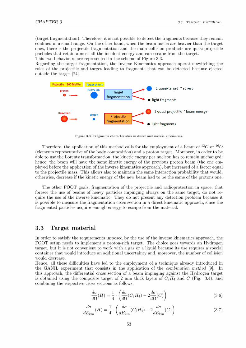
CHAPTER 3 3.3. TARGET MATERIAL
(target fragmentation). Therefore, it is not possible to detect the fragments because they remainconfined in a small range. On the other hand, when the beam nuclei are heavier than the targetones, there is the projectile fragmentation and the main collision products are quasi-projectileparticles that retain almost all the incident energy and can escape from the target.This two behaviours are represented in the scheme of Figure 3.3.Regarding the target fragmentation, the Inverse Kinematics approach operates switching theroles of the projectile and target leading to fragments that can be detected because ejectedoutside the target [24].
Figure 3.3: Fragments characteristics in direct and inverse kinematics.
Therefore, the application of this method calls for the employment of a beam of 12C or 16O(elements representative of the body composition) and a proton target. Moreover, in order to beable to use the Lorentz transformation, the kinetic energy per nucleon has to remain unchanged;hence, the beam will have the same kinetic energy of the previous proton beam (the one em-ployed before the application of the inverse kinematics approach), but increased of a factor equalto the projectile mass. This allows also to maintain the same interaction probability that would,otherwise, decrease if the kinetic energy of the new beam had to be the same of the protons one.
The other FOOT goals, fragmentation of the projectile and radioprotection in space, thatforesee the use of beams of heavy particles impinging always on the same target, do not re-quire the use of the inverse kinematic. They do not present any detection problem because itis possible to measure the fragmentation cross section in a direct kinematic approach, since thefragmented particles acquire enough energy to escape from the material.
3.3 Target material
In order to satisfy the requirements imposed by the use of the inverse kinematics approach, theFOOT setup needs to implement a proton-rich target. The choice goes towards an Hydrogentarget, but it is not convenient to work with a gas or a liquid because its use requires a specialcontainer that would introduce an additional uncertainty and, moreover, the number of collisionwould decrease.Hence, all these difficulties have led to the employment of a technique already introduced inthe GANIL experiment that consists in the application of the combination method [9]. Inthis approach, the differential cross section of a beam impinging against the Hydrogen targetis obtained using the composite target of 2 mm thick layers of C2H4 and C (Fig. 3.4), andcombining the respective cross sections as follows:
dσ
dΩ(H) =
1
4·(dσ
dΩ(C2H4)− 2
dσ
dΩ(C)
)(3.6)
dσ
dEkin(H) =
1
4·(
dσ
dEkin(C2H4)− 2
dσ
dEkin(C)
)(3.7)
53
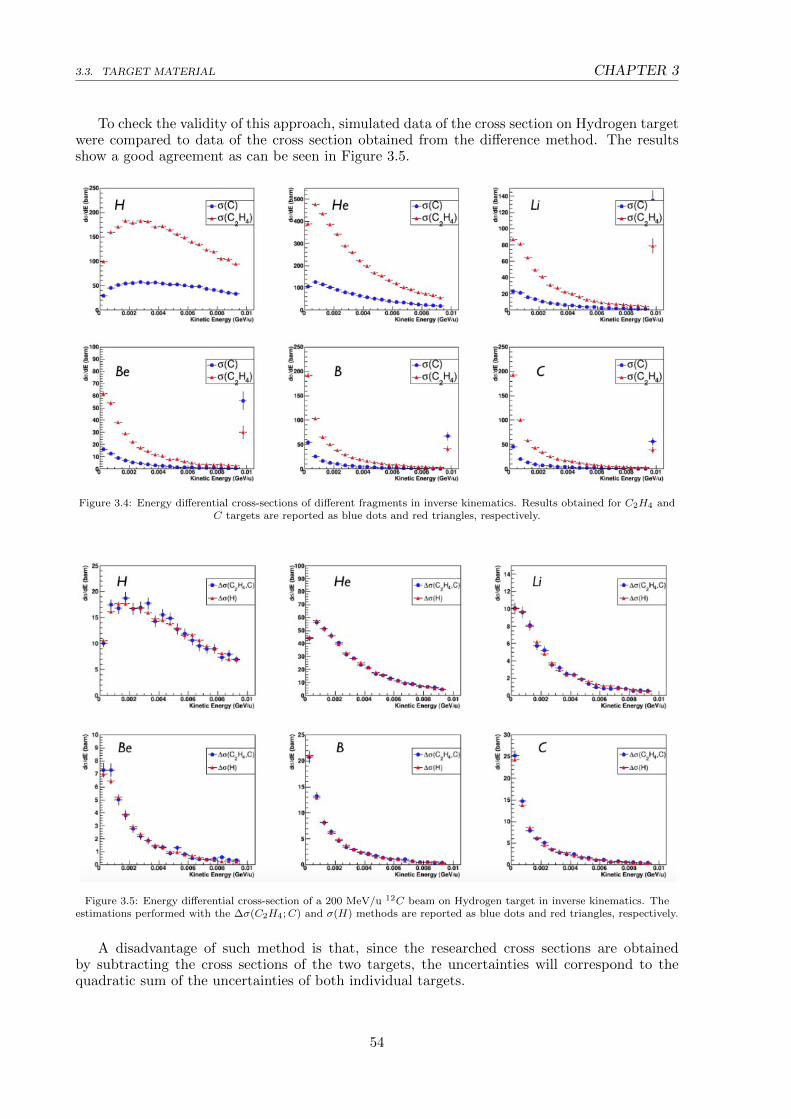
3.3. TARGET MATERIAL CHAPTER 3
To check the validity of this approach, simulated data of the cross section on Hydrogen targetwere compared to data of the cross section obtained from the difference method. The resultsshow a good agreement as can be seen in Figure 3.5.
Figure 3.4: Energy differential cross-sections of different fragments in inverse kinematics. Results obtained for C2H4 andC targets are reported as blue dots and red triangles, respectively.
Figure 3.5: Energy differential cross-section of a 200 MeV/u 12C beam on Hydrogen target in inverse kinematics. Theestimations performed with the ∆σ(C2H4;C) and σ(H) methods are reported as blue dots and red triangles, respectively.
A disadvantage of such method is that, since the researched cross sections are obtainedby subtracting the cross sections of the two targets, the uncertainties will correspond to thequadratic sum of the uncertainties of both individual targets.
54

CHAPTER 3 3.4. MATHEMATICAL FORMULATION OF THE INVERSE KINEMATICS
3.4 Mathematical Formulation of the Inverse Kinematics
The projectile particles employed in Hadrontherapy proceed at relativistic velocities and, con-sequently, the interaction with the target takes place in the same relativistic condition. To usethe inverse kinematics approach is necessary to apply the Lorentz transformation that allows toswitch from the laboratory frame to the “patient frame”.It is a linear transformation that converts the coordinates between two inertial reference framesmoving at constant velocity relative to each other. This mathematical tool may also include a ro-tation of space; in the absence of rotations the transformation is called a Lorentz boost (Fig. 3.6).
Figure 3.6: Scheme of the Lorentz transformation between the two reference frames.
The first step in the development of a relativistic kinematics is to determine the new coor-dinates transformation. To do so, it is necessary to consider two frames S and S’ moving withconstant relative velocity along the positive z axis, and such that their origins coincide at t = 0.S indicates the laboratory frame in which the incident beam, of heavy charged ions, impingeson the stationary hydrogen target. S’, instead, represents the patient frame in which target andprojectile material are switched, meaning that the beam is made of protons and the target iscomposed of elements that constitutes the human body. Therefore, the coordinates that can befound experimentally are the one within the laboratory frame, while the coordinates denotedwith a prime are measured in the patient frame.
Considering A as a generic four-vector in the laboratory frame, it is defined as an object offour components:
A = [a0, a1, a2, a3] = [a0,~a] (3.8)
where the first component is the temporal one and the other three indicate the spatial terms.Taken two inertial frames, S with x,y,z coordinates and S’ with x’, y’, z’, is possible to applythe Lorentz transformation to the four-vector A, in the S reference frame, and transform it inthe four-vector A’ expressed in the “boosted” S’ system (the patient frame where the targetfragmentation takes place). The transformation can be written as:
A′ = ΛA (3.9)
where Λν is a 4 × 4 matrix.
55

3.4. MATHEMATICAL FORMULATION OF THE INVERSE KINEMATICS CHAPTER 3
In the particular case of FOOT, the two reference frames motion is along a specific directionthat can be identified with the z axis and the transformation is expressed as:
a′0
a′1
a′2
a′3
=
γ 0 0 −βγ0 1 0 0
0 0 1 0
−βγ 0 0 γ
·a0
a1
a2
a3
=
γa0 − βγa3
a1
a2
−βγa0 + γa3
(3.10)
where β = v/c and v (it corresponds to vz) indicates the velocity of the S’ system in relation
to S, and γ = 1/√
1− β2.
The matrix Λ of the transformation has the property that:
Λ−1(β) = Λ(−β) (3.11)
therefore, the inverse transformation is defined as:
a0
a1
a2
a3
=
γ 0 0 βγ
0 1 0 0
0 0 1 0
βγ 0 0 γ
·a′0
a′1
a′2
a′3
=
γa0 + βγa3
a1
a2
+βγa0 + γa3
(3.12)
Replacing the generic four-vector with the position one, the relations obtained from thedirect approach can be written as:
ct′ = γ(ct− βz) (3.13)
x′ = x (3.14)
y′ = y (3.15)
z′ = γ(z − βct) (3.16)
Considering the momentum P it is also a four-vector, defined as:
P = [E/c, ~p] = [mγc,mγ~v] (3.17)
and its transformation is:
E′/c = γ(E/c− βpz) (3.18)
p′x = px (3.19)
p′y = py (3.20)
p′z = γ(pz − βE/c) (3.21)
In the laboratory reference frame S, the four-vectors of the beam P1 and the target P2 are:
P1 = [E1/c, ~p1] (3.22)
P2 = [E2/c,~0] = [m2c,~0] (3.23)
56
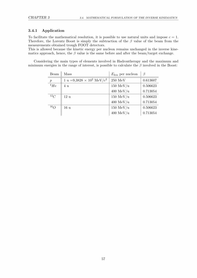
CHAPTER 3 3.4. MATHEMATICAL FORMULATION OF THE INVERSE KINEMATICS
3.4.1 Application
To facilitate the mathematical resolution, it is possible to use natural units and impose c = 1.Therefore, the Lorentz Boost is simply the subtraction of the β value of the beam from themeasurements obtained trough FOOT detectors.This is allowed because the kinetic energy per nucleon remains unchanged in the inverse kine-matics approach, hence, the β value is the same before and after the beam/target exchange.
Considering the main types of elements involved in Hadrontherapy and the maximum andminimum energies in the range of interest, is possible to calculate the β involved in the Boost:
Beam Mass Ekin per nucleon β
p 1 u =9,3828 × 10² MeV/c2 250 MeV 0.6136074He 4 u 150 MeV/u 0.506623
400 MeV/u 0.71305412C 12 u 150 MeV/u 0.506623
400 MeV/u 0.71305416O 16 u 150 MeV/u 0.506623
400 MeV/u 0.713054
57

3.5. FRAGMENTS CHARACTERISTICS IN DIRECT AND INVERSE KINEMATICS CHAPTER 3
3.5 Fragments characteristics in Direct and Inverse Kinematics
The necessity for the application of the Inverse Kinematics approach arises from the requirementto measure nuclear fragmentation cross sections of the target. The employment of protontherapyin actual medical treatments demands for the precise knowledge of the effect caused by thesefragments in order to delineate an adequate treatment planning system. As mentioned in Section3.2, it is not possible to detect the produced fragments because of their low velocity (hence, lowkinetic energy) that prevents them to escape the target setup without any possibility of beingdetected.In order to study the interaction of a proton beam with the human tissue (made up of heavynuclei, typically C or O) it is necessary to switch the beam/target roles by analyzing the collisionof a C or O beam on a proton target. Obviously, the method is valid only if the β (or, equivalently,the kinetic energy per nucleon) of the beams (protons in direct kinematics and C or O ions inthe inverse kinematics) is the same. This request is necessary because the transformation matrix(see Section 3.4) depends only on the parameter β of the beam. In this way it is assured that theresults obtained with a proton beam on a heavy nuclei target, in direct kinematics, is exactlythe same of a heavy beam impinging on a proton target, in the inverse kinematics approach.
Direct Kinematics
Considering a simulated interaction of an Oxygen-16 beam of 200 MeV/u on a C2H4 target, 2mm thick, the fragments are emitted with a slightly lower velocity than the incident beam andthe kinetic energy distribution per nucleon appears to be peaked around the incident velocityvalue (Fig. 3.7).The kinetic energy distribution becomes narrower with increasing number of nucleons, whilelighter fragments present a smeared configuration. This behaviour is caused by the fragmentsmass that decreases and becomes more similar to that of the protons within the target; conse-quently, the fragments are more likely to interact with the target resulting in a change of thefragments velocity.
Figure 3.7: Fragments kinetic energy distribution per nucleon, obtained through a simulated interaction between anOxygen-16 beam of 200 MeV/u and a C2H4 target.
58

CHAPTER 3 3.5. FRAGMENTS CHARACTERISTICS IN DIRECT AND INVERSE KINEMATICS
The most recurring fragments produced in the collision are: 1H, D, T, 3He, 4He, 7Li, 9Be,11B, 12C, 14N, 16O. The Figure 3.8 shows their kinetic energy; it increases when the number ofnucleons becomes greater.The energies of the fragments can reach the order of some GeV.
Figure 3.8: Kinetic energy distribution of fragments, obtained through a simulated interaction between an Oxygen-16beam of 200 MeV/u and a C2H4 target. The kinetic energy is expressed in GeV.
59

3.5. FRAGMENTS CHARACTERISTICS IN DIRECT AND INVERSE KINEMATICS CHAPTER 3
The plots for each fragment are shown in Figures 3.9 and 3.10 and they confirm what tolduntil this point. The peak appears in correspondence of 200 MeV × the number of nucleons,while the distributions are narrower for heavier fragments.
Figure 3.9: Kinetic energy distribution of 1H, D, T, 3He, 4He, 7Li in direct kinematics (obtained through a simulatedinteraction between an Oxygen-16 beam of 200 MeV/u and a C2H4 target). The kinetic energy is expressed in GeV.
60

CHAPTER 3 3.5. FRAGMENTS CHARACTERISTICS IN DIRECT AND INVERSE KINEMATICS
Figure 3.10: Kinetic energy distribution of 9Be, 11B, 12C, 14N, 16O in direct kinematics (obtained through a simulatedinteraction between an Oxygen-16 beam of 200 MeV/u and a C2H4 target). The kinetic energy is expressed in GeV.
61
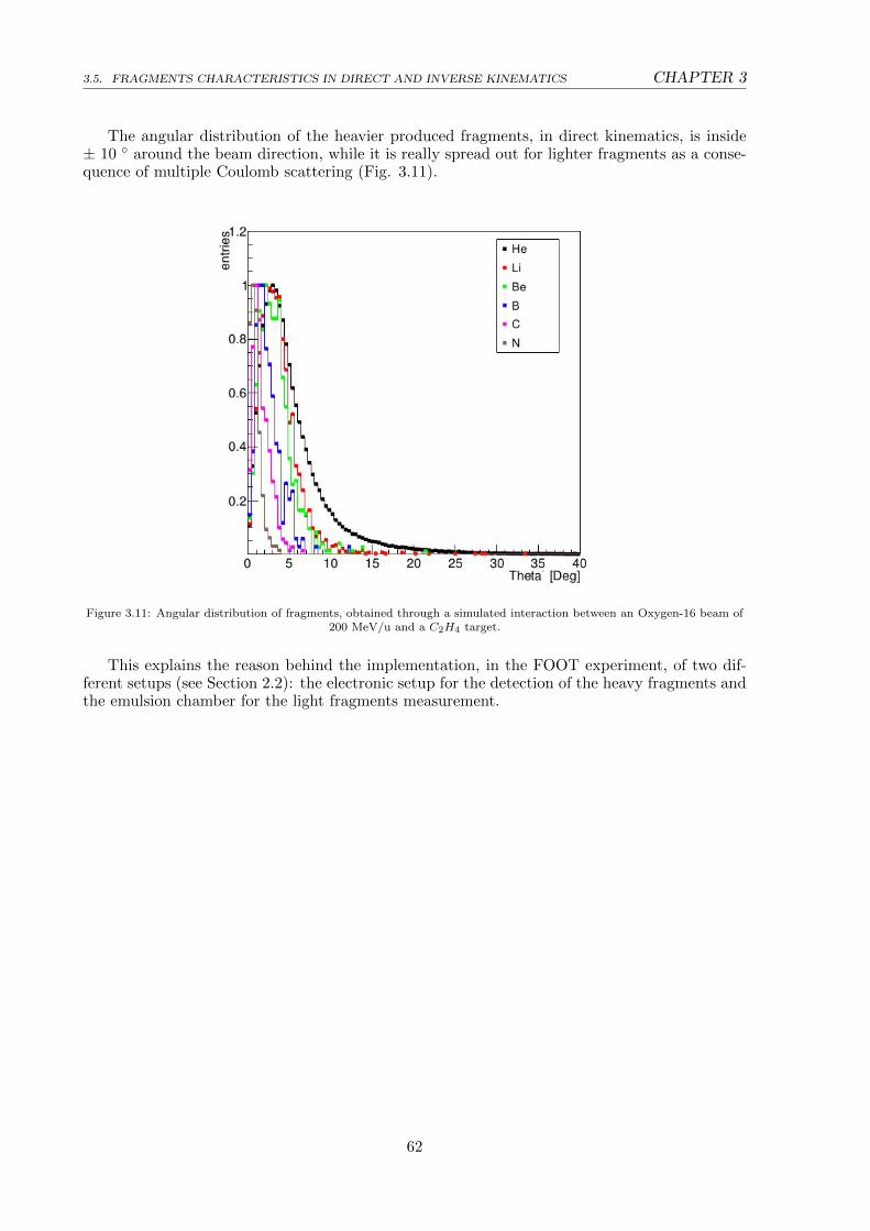
3.5. FRAGMENTS CHARACTERISTICS IN DIRECT AND INVERSE KINEMATICS CHAPTER 3
The angular distribution of the heavier produced fragments, in direct kinematics, is inside± 10 around the beam direction, while it is really spread out for lighter fragments as a conse-quence of multiple Coulomb scattering (Fig. 3.11).
Figure 3.11: Angular distribution of fragments, obtained through a simulated interaction between an Oxygen-16 beam of200 MeV/u and a C2H4 target.
This explains the reason behind the implementation, in the FOOT experiment, of two dif-ferent setups (see Section 2.2): the electronic setup for the detection of the heavy fragments andthe emulsion chamber for the light fragments measurement.
62

CHAPTER 3 3.5. FRAGMENTS CHARACTERISTICS IN DIRECT AND INVERSE KINEMATICS
Inverse Kinematics
As expected, the kinetic energy distribution of the fragments in inverse kinematics is limited toa range of few MeV (Fig. 3.12) that prevents the fragmentation products to escape the targetand to be detected.The lighter fragments have a different distribution that extends to higher energies as a conse-quence of the smeared distribution that they had in direct kinematics. In fact, it is crucial tohave high resolutions on the kinematic quantities in order to appreciate small differences in thedistribution in the inverse kinematics approach. If the measurements in direct kinematics arenot precise enough, the inaccuracy propagates in the inverse kinematics case affecting most ofthe results.In order to obtain cross section measurements with a resolution at the level of 5%, the precisionrequired for the kinetic energy has to be of 1-2 MeV in the inverse kinematics approach.
Figure 3.12: Fragments kinetic energy distribution per nucleon, obtained through a simulated interaction, in inversekinematics, between an Oxygen-16 beam of 200 MeV/u and a C2H4 target.
63
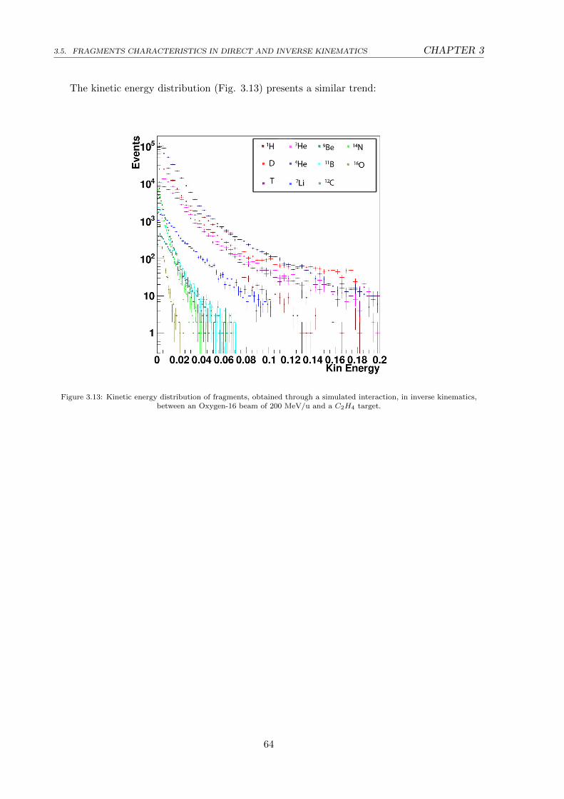
3.5. FRAGMENTS CHARACTERISTICS IN DIRECT AND INVERSE KINEMATICS CHAPTER 3
The kinetic energy distribution (Fig. 3.13) presents a similar trend:
Figure 3.13: Kinetic energy distribution of fragments, obtained through a simulated interaction, in inverse kinematics,between an Oxygen-16 beam of 200 MeV/u and a C2H4 target.
64

CHAPTER 3 3.5. FRAGMENTS CHARACTERISTICS IN DIRECT AND INVERSE KINEMATICS
Considering each single fragment (Fig. 3.14- Fig. 3.15) the distributions are:
Figure 3.14: Kinetic energy distribution of 1H, D, T, 3He, 4He, 7Li in inverse kinematics (obtained through a simulatedinteraction between an Oxygen-16 beam of 200 MeV/u and a C2H4 target). The kinetic energy is expressed in GeV.
65

3.5. FRAGMENTS CHARACTERISTICS IN DIRECT AND INVERSE KINEMATICS CHAPTER 3
Figure 3.15: Kinetic energy distribution of 9Be, 11B, 12C, 14N, 16O in inverse kinematics (obtained through a simulatedinteraction between an Oxygen-16 beam of 200 MeV/u and a C2H4 target). The kinetic energy is expressed in GeV.
In the inverse kinematics approach the angular distribution of the produced fragments losesall its meaning. In fact, due to the very low value of the kinetic energy distribution and, conse-quently, to the very small range in the human tissue, it has, from a therapeutic point of view,a negligible influence on the fragments path since it changes it of only few micrometers.
66
Conclusions
The goal of the FOOT (FragmentatiOn Of Target) experiment is to improve the knowledge ofthe nuclear processes that take place during the beam/patient interactions in the hadrontherapytreatments. The collisions of the therapeutic beams with the nuclei of the human body causethe production of fragments that can release their energy outside of the tumor volume. Theexperiment was designed to measure the fragmentation cross section in order to accuratelyevaluate the dose deposition in the patient’s body.The kinematic characteristics of the produced fragments depend on the nuclear fragmentationprocess. In particular, if the fragments derive from the beam fragmentation, they acquire almostall the initial kinetic energy of the beam and can reach the detectors. On the contrary, if theyare produced by the target fragmentation, their kinetic energy and, consequently, their rangesare small (tens of micrometers), preventing the possibility of overstepping the target thicknessand to be detected.In order to study the target fragmentation the strategy of the FOOT experiment is to usethe Inverse Kinematics approach. With this technique is possible to exchange the roles ofbeam and target causing the beam fragmentation (instead of the target) and promoting thecreation of secondary fragments with high kinetic energy and longer ranges. In this way it ispossible to study the fragmentation of the human nuclei, caused by a proton beam, through theimplementation of an enriched hydrogen target and using Carbon or Oxygen beams.This approach, despite being used in few experiments in the past, has guaranteed satisfactoryresults. The validity of this method has been faced in this thesis analyzing simulated data andgenerating the kinematics quantities of the most produced fragments in both inverse and directapproaches. From the comparison of the kinetic energy distributions in the two approaches, itis evident the importance of achieving precise measurements in direct kinematics in order tonot affect the results in the inverse one. Therefore, to obtain cross section measurements with aresolution level of 5%, the precision required for the kinetic energy has to be of 1-2 MeV in theinverse kinematics approach.
67

68

Bibliography
[1] http://pathology.jhu.edu/pc/BasicTypes1.php?area=ba
[2] A. Schipler, G. Iliakis, DNA double-strand–break complexity levels and their possible contri-
butions to the probability for error-prone processing and repair pathway choice, Nucleic Acids
Research, vol. 41, no. 16, pp. 7589–7605, 2013.
[3] O. Desoukya, G. Zhouba, Biophysical and radiobiological aspects of heavy charged particles,
Journal of Taibah University for Science, no. 10, pp. 187-194, 2016.
[4] H. Song, S. Senthamizhchelvan, R. F. Hobbs, G. Sgouros, Alpha Particle Emitter Radiolabeled
Antibody for Metastatic Cancer: What Can We Learn from Heavy Ion Beam Radiobiology?,
Antibodies, no. 1, pp. 124-148, 2012.
[5] D. Schardt, T. Elsasser, D. Schulz-Ertner, Heavy-ion tumor therapy: Physical and radiobio-
logical benefits, Reviews of Modern Physics, vol. 82, pp. 383-425, 2010.
[6] http://enlight.web.cern.ch/what-is-hadron-therapy
[7] O. Jakel, C. P. Karger, J. Debus, The future of heavy ion radiotherapy, Med Phys., vol. 35,
no. 12, pp. 5653-63, 2008.
[8] F. Tommasino, M. Durante, Proton Radiobiology, Cancers, no. 7, pp. 353-381, 2015.
[9] J. Dudouet, D. Juliani, J.C. Angelique, B. Braunn, J. Colin et al., Double differential frag-
mentation cross-section measurements of 95 MeV/u 12C on thin targets for hadrontherapy,
Phys. Rev. C, American Physical Society, vol. 88, no. 2, 2013.
[10] M. Toppi et al., Measurement of fragmentation cross sections of 12C ions on a thin gold
target with the FIRST apparatus, Phys. Rev. C, vol. 93, no. 6, p. 064601, 2016.
[11] G. De Lellis et al., Measurement of the fragmentation of Carbon nuclei used in hadron-
therapy, Nucl. Phys. A, vol. 853, no. 1, pp. 124–134, 2011.
[12] F. Tommasino et al., New ions for therapy, Int. J. Part. Ther., vol. 2, no. 3, pp. 428–438,
2015.
[13] B. Knausl et al., Can particle beam therapy be improved using helium ions? - a planning
study focusing on pediatric patients, Acta Oncol., vol. 55, no. 6, pp. 751–759, 2016.
69
BIBLIOGRAPHY CHAPTER 3
[14] R. Grun et al., Assessment of potential advantages of relevant ions for particle therapy: A
model based study, Med. Phys., vol. 42, no. 2, pp. 1037–1047, 2015.
[15] M. Durante, F. Cucinotta, Physical basis of radiation protection in space travel, Rev. Mod.
Phys., vol. 83, no. 4, p. 1245, 2011.
[16] G. De Lellis et al., Nuclear emulsions, Elementary Particles: Detectors for Particles and
Radiation, vol 21B, Springer, 2011.
[17] G. De Lellis, S. Buontempo, Emulsion Cloud Chamber technique to measure the fragmen-
tation of a high-energy carbon beam, J. Instrum, vol 2, p P06004, 2007.
[18] G. J. Russell, Spallation Physics - An Overview, ICANS - XI International Collaboration
on Advanced Neutron Sources, KEK, Tsukuba, October 22-26, 1990.
[19] R. Serber, Nuclear Reactions at High Energies, Phys.Rev., vol. 72, no. 11, pp. 1114-1115,
1947.
[20] I. Schall, D. Schardt et al., Charge-changing nuclear reactions of relativistic light-ion beams
(5 ≤ Z ≤ 10) passing through thick absorbers, Nuclear Instruments and Methods in Physics
Research B, 117, pp. 221-234, 1996.
[21] L. Sihver, C. H. Tsao et al., Total reaction and partial cross section calculations in proton-
nucleus (Zt ≤ 26) and nucleus-nucleus reactions (Zp and Zt ≤ 26)., Phys. Rev. C, vol. 47,
pp. 1225–1236, 1993.
[22] R. Ravichandran, Artificial body fluid as tissue substitute for radiotherapy beam analysis:
A theoretical evaluation of its electron density information, J. Med. Phys., vol. 42(3), pp.
191–193, Jul-Sep 2017.
[23] K. P. Artemov et al., Effective method of study of α cluster states, Sov. J. Nucl. Phys., vol
52, no. 3, pp. 408-411, 1990.
[24] J Walshe et al., The thick target inverse kinematics technique with a large acceptance silicon
detector array, Journal of Physics: Conference Series, no. 569, 2014.
70