the ideal sprinkler from 4’ strips to 30’ · PDF file> new systems —...
8
MPR US — 7/09 THE IDEAL SPRINKLER from 4’ strips to 30’ radius
Transcript of the ideal sprinkler from 4’ strips to 30’ · PDF file> new systems —...

MPR US — 7/09
the ideal sprinklerfrom 4’ strips to 30’ radius

removable inlet filter keeps
sprinkler free from internal
debris
The MP Rotator. A revolutionary sprinkler setting a new standard for water efficiency in the turf & landscape industry. It is a multi-stream rotor the size of a spray nozzle. It fits any conventional spray head body or shrub adapter, transforming it into a high uniformity, low precip-itation rate sprinkler with matched precipitation even after arc and radius adjustment.
A wATeR conSeRvATion Tool·�� Multiple rotating streams provide superior uniformity·�� Automatic matched precipitation even after arc & radius adjustment·�� Low precipitation rate reduces runoff on slopes & tight soils
A flexible deSign Tool ·�� Ideal for 4’ strip - 30’ spacings — any model
can be combined on the same zone ·�� Eliminates the uncertainty associated
with nozzle trees and rotor nozzling
PRoven dURAbiliTy & ReliAbiliTy�·�� Rotator® Technology proven in demanding
agricultural conditions since 1987·�� One moving part·�� “Double-pop” flushes on start-up and shut-down
SiMPle And qUick AdjUSTMenTS ·�� Easy arc adjustment ·�� Easy radius adjustment — up to 25%·�� No nozzle to change
2
MP Rotator shown popped up, in operating mode; when watering cycle ends MP Rotator pops down before spray head retracts
color-code system for identifying models (see page 4)
patented “double pop”
keeps sprinkler free from
external debris
male threadalso available
inleT ScReen CAUTION: Do not run the MP Rotator without the inlet screen provided!
lefT edge indicAToRarc is clockwise from this mark
ARc AdjUSTMenT** Ringclockwise to increase the arc
RAdiUS AdjUSTMenT* ScRewclockwise to decrease radius
*Built-in slip clutch prevents damage from over adjustment. **While water is on, use orange tool to engage built-in ratchet; move past the left or right stop until left edge is aligned.
MP MATchSTickSAveS yoUR
bAck & kneeS
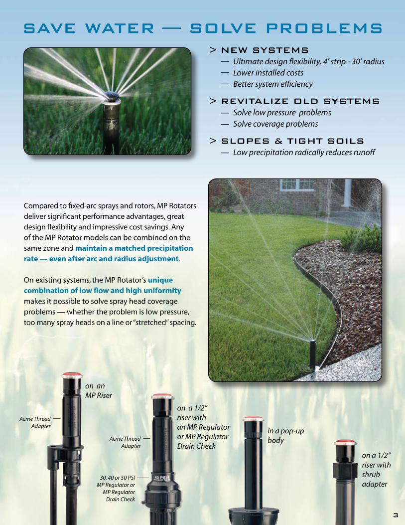
> new systems — Ultimate design flexibility, 4’ strip - 30’ radius — Lower installed costs — Better system efficiency
> revitalize old systems — Solve low pressure problems — Solve coverage problems
> slopes & tight soils — low precipitation radically reduces runoff
save water — solve problems
3
Compared to fixed-arc sprays and rotors, MP Rotators deliver significant performance advantages, great design flexibility and impressive cost savings. Any of the MP Rotator models can be combined on the same zone and maintain a matched precipitation rate — even after arc and radius adjustment.
On existing systems, the MP Rotator’s unique combination of low flow and high uniformity makes it possible to solve spray head coverage problems — whether the problem is low pressure, too many spray heads on a line or “stretched” spacing.
in a pop-up body
on a 1/2”riser with an MP Regulator or MP Regulator Drain Check
on anMP Riser
30, 40 or 50 PSI MP Regulator or
MP RegulatorDrain Check
Acme ThreadAdapter
on a 1/2” riser with shrubadapter
Acme ThreadAdapter

4
Specify Model & Arc. Add “T” to Model Name to specify Male Thread.
210-270° 360°
adJUstable radiUs mp1000
mp2000
mp3000
adJUstable arCModel Arc
Example: MP2000 90-210
8‘ 15’RADIUS REDUCTION
stream height @ 30 PSI = 16”
13’ 21’RADIUS REDUCTION
stream height @ 30 PSI = 40”
22’ 30’RADIUS REDUCTION
stream height @ 40 PSI = 79”
8‘RADIUS REDUCTION
stream height @ 30 PSI = 10”
15’
45-105°
MP Corner
Turquoise
The MP Corner is designed for tight corners that are difficult to irrigate properly with conventional sprinklers. It has an adjustable arc from 45° to 105°, maintains MPR at any arc, any radius and can be placed on the same zone with any other MP Rotator model.
Maintain Matched Precipitation — Any Model, Any Arc, Any Radius
mp Corner
exAMPle @ 45°
90-210°
MP1000 90-210 MP1000 360
Olive
MP2000 90-210
Red
MP2000 360MP2000 210-270
Green
MP3000 90-210
Blue
Black
MP3000 210-270
Yellow
MP3000 360
Gray
The three new MP Strip models of the MP Rotator family offer an exciting alternative to conventional spray heads to meet the challenges of irrigating strip areas. Strip models offer improved uniformity and excellent wind-fighting ability. The reduced flow rate compared to conventional sprays makes longer runs and/or fewer zones possible.
s EXAMPLE WITH TRIANGULAR SPACING
15’ 15’ 15’ 15’
5’MP Left Strip
MP Side Strip
MP Side Strip
MP Side Strip
MP Right Strip
mp strip MP LEFT STRIP MP RIGHT STRIPMP SIDE STRIP
CopperIvory Brown
Maroon Light Blue
MP1000 210-270

5
*To obtain full radius reduction for the MP1000 and MP2000, operate at a maximum of 30 PSI. ** When operating the MP3000 at full radius reduction maintain a minimum pressure of 40 PSI to assure reliable operation. Radius measured on a 4” high riser. Precipitation rates are based on head-to-head throw coverage.
Arc Setting
90°
180°
210°
270°
360°
in/hr. ▲0.49
0.45
0.45
0.43
0.45
0.47
0.50
0.51
0.48
0.48
0.45
0.48
0.50
0.53
0.51
0.48
0.48
0.45
0.48
0.50
0.53
0.52
0.48
0.48
0.45
0.48
0.50
0.53
0.51
0.48
0.48
0.45
0.48
0.50
0.53
GPM
0.69
0.74
0.80
0.86
0.91
0.96
1.01
1.44
1.58
1.70
1.82
1.93
2.04
2.13
1.68
1.84
1.99
2.12
2.25
2.37
2.49
2.19
2.37
2.55
2.73
2.89
3.06
3.22
2.88
3.15
3.40
3.64
3.86
4.07
4.27
in/hr. ▲0.43
0.39
0.39
0.37
0.39
0.41
0.43
0.44
0.42
0.42
0.39
0.41
0.44
0.46
0.44
0.42
0.42
0.39
0.41
0.43
0.46
0.45
0.42
0.42
0.39
0.41
0.44
0.46
0.44
0.42
0.42
0.39
0.41
0.44
0.46
PSI
25
30
35
40
45
50
55
25
30
35
40
45
50
55
25
30
35
40
45
50
55
25
30
35
40
45
50
55
25
30
35
40
45
50
55
Rad. Ft.
25
27
28
30
30
30
30
25
27
28
30
30
30
30
25
27
28
30
30
30
30
25
27
28
30
30
30
30
25
27
28
30
30
30
30
mp3000**
blU
e =
90-2
10°
gray =
360°
yello
w =
210-2
70°
mp1000*
mar
oo
n =
90-2
10°
-
0.50
0.47
0.46
0.45
0.44
0.43
-
0.65
0.71
0.75
0.80
0.84
0.87
-
0.43
0.40
0.39
0.39
0.38
0.37
25
30
35
40
45
50
55
oliv
e =
360°
in/hr. ▲-
0.50
0.46
0.45
0.45
0.43
0.43
-
0.50
0.46
0.45
0.45
0.43
0.43
-
0.50
0.46
0.45
0.45
0.43
0.43
-
0.50
0.46
0.45
0.45
0.43
0.43
GPM
-
0.16
0.18
0.19
0.20
0.21
0.22
-
0.32
0.35
0.37
0.40
0.41
0.43
-
0.37
0.41
0.43
0.46
0.48
0.50
-
0.48
0.54
0.57
0.60
0.63
0.66
Rad. Ft.
-
12
13
14
14
14
15
-
12
13
14
14
15
15
-
12
13
14
14
15
15
-
12
13
14
14
15
15
PSI
25
30
35
40
45
50
55
25
30
35
40
45
50
55
25
30
35
40
45
50
55
25
30
35
40
45
50
55
in/hr. ▲-
0.43
0.40
0.39
0.39
0.38
0.37
-
0.43
0.40
0.39
0.39
0.38
0.37
-
0.43
0.40
0.39
0.39
0.38
0.37
-
0.43
0.40
0.39
0.39
0.38
0.37
-
12
13
14
14
15
15
in/hr. ▲0.48
0.45
0.46
0.44
0.42
0.40
0.43
0.50
0.49
0.47
0.45
0.43
0.41
0.43
0.50
0.49
0.47
0.45
0.43
0.41
0.43
0.50
0.49
0.47
0.45
0.43
0.41
0.43
0.50
0.49
0.47
0.45
0.43
0.41
0.43
GPM
0.31
0.33
0.37
0.40
0.42
0.44
0.47
0.58
0.63
0.69
0.74
0.78
0.83
0.85
0.68
0.74
0.80
0.86
0.92
0.97
1.01
0.87
0.95
1.03
1.10
1.17
1.23
1.30
1.16
1.27
1.37
1.47
1.56
1.64
1.70
in/hr. ▲0.41
0.39
0.39
0.39
0.37
0.35
0.37
0.44
0.42
0.41
0.39
0.38
0.36
0.37
0.44
0.42
0.41
0.39
0.38
0.36
0.37
0.44
0.42
0.41
0.39
0.38
0.36
0.37
0.44
0.42
0.41
0.39
0.38
0.36
0.37
PSI
25
30
35
40
45
50
55
25
30
35
40
45
50
55
25
30
35
40
45
50
55
25
30
35
40
45
50
55
25
30
35
40
45
50
55
Rad. Ft.
17
18
19
20
21
22
22
16
17
18
19
20
21
21
16
17
18
19
20
21
21
16
17
18
19
20
21
21
16
17
18
19
20
21
21
mp2000*
blaC
k =
90-2
10°
gr
een
= 2
10-2
70°
lt. b
lU
e =
210-2
70°
red
= 3
60°
Arc Setting
45°
90°
105°
mp Corner
tU
rq
Uo
ise =
45-1
05°
GPM
-
0.17
0.18
0.19
0.21
0.22
0.23
0.31
0.34
0.36
0.39
0.41
0.43
0.46
0.36
0.39
0.42
0.45
0.48
0.51
0.53
Rad. Ft.
-
12
13
14
14
15
15
11
12
13
14
14
15
15
11
12
13
14
14
15
15
PSI
25
30
35
40
45
50
55
25
30
35
40
45
50
55
25
30
35
40
45
50
55
PSI Unadjusted Reduced Precip.*** Radius Radius Rate in/hr GPM GPM n
30 .19 .14 .49 35 .21 .15 .49 40 .22 .16 .48 45 .23 .17 .48 50 .25 .18 .48 55 .26 .19 .48
PSI Unadjusted Reduced Precip.*** Radius Radius Rate in/hr GPM GPM n
30 .19 .14 .49 35 .21 .15 .49 40 .22 .16 .48 45 .23 .17 .48 50 .25 .18 .48 55 .26 .19 .48
PSI Unadjusted Reduced Precip.*** Radius Radius Rate in/hr GPM GPM n
30 .38 .27 .49 35 .41 .30 .49 40 .44 .32 .48 45 .47 .34 .48 50 .49 .36 .48 55 .51 .38 .48
mp right stripmp left strip mp side strip
30 psi15’
5’ .19 GPM
12’
4’ .14 GPM
24’
4’
30’
5’
30 psi
.38 GPM
.27 GPM
30 psi15’
5’.19 GPM
12’
4’ .14 GPM
17’
6’
14’
5’
50 psi
.25 GPM
.18 GPM
28’
5’
34’
6’
50 psi
.49 GPM
.36 GPM
17’
6’
14’
5’
50 psi
.25 GPM
.18 GPM
***The slightly higher precipitation rate of the MP Strips is intentional. It compensates for the significant proportion of edge watering in strip applications.

6
Based on well known pop-up body technology, the MPR40 body provides 40 psi pressure regulation and a check valve. This delivers the water saving function of a drain check valve at a pressure that will give full range performance from the MP Rotator. The MPR40 body and the non-regulated or checked MPR body are high-quality sprinkler bodies made specifically to complement the MP Rotator.
ModelS MPR40 SPRinkleR body* wiTh 40 PSi RegUlAToR & check vAlve (gRAy cAP) MPR40-00 Shrub MPR40-04CV 4” Pop-up MPR40-06CV 6” Pop-up MPR40-12CV 12” Pop-up
MPR SPRinkleR body* wiThoUT RegUlAToR & check vAlve (blAck cAP) MPR-04 4” Pop-up MPR-06 6” Pop-up MPR-12 12” Pop-up
diMenSionS• Overall height: 4” = 5 7⁄8” 6” = 8 3⁄4” 12” = 16 1⁄8” • 1⁄2” female inlet NPT• Exposed diameter: 2 1⁄4”
oPeRATing SPecificATionS• Recommended pressure range: for MPR model 15-100 PSI; for MPR40 model 45-100 PSI • flow-by: 0 at 10 PSI or greater; 0.1 GPM otherwise• check height: Up to 14’ elevation head
oPTionS AvAilAble• Field-installed black rubber cover • Field-installed reclaimed water identification snap-on cover
10
20
20 30 40 50 70 80 90
30
40
50
MP3000 @ 360
MP2000 @ 180
MP1000 @ 90
Optimum pressurefor the MP Rotator
(40 PSI)
Inlet Pressure (PSI)
Pres
sure
at N
ozzl
e (P
SI)
S P E C I F I C A T I O N G U I D E
EXAMPLE: MPR40 - 04 - CV - MP200090
MODELMPR40 = MPR40 (Includes factory-installed 40 PSI pressure regulator)
POP-UP HEIGHT00 burhS = 04 pu-poP "4 = 06 = 6" Pop-up12 pu-poP "21 =
OPTIONSCV = Factory-installed check valve (Pop-up models only)
MP ROTATORSSee MP Rotator Speci� cation Guide for details
mpr40 & mpr pop-Up bodies
The MPR40 SPRINkleR BOdy• Built-in regulator set at 40 psi • New easy-to identify gray cap • Factory-installed check valve
Two-piece ratchet design facilitates quick and easy adjustability for both the MPR40 and the MPR sprinkler bodies.
7
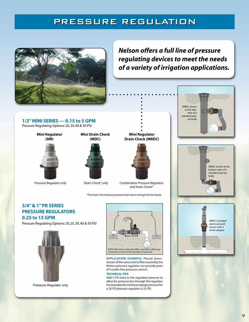
pressUre regUlation
Combination Pressure Regulator and Drain Check*
MRDC (installed above ground) shown with a shrub adapter
FLOW
APPlicATion exAMPle: Placed down-stream of the valve and/or filter assembly, the Nelson pressure regulator can provide years of trouble-free pressure control.
TechnicAl TiPSAdd 5 PSI extra to the regulated pressure to allow for pressure loss through the regulator. For example, the minimum design pressure for a 20 PSI pressure regulator is 25 PSI.
NOTE: Add unions to the valve/filter assembly to allow easy maintenance of any of the assembly components.
1/2” Mini SeRieS — 0.15 to 5 gPMPressure Regulating Options: 20, 30, 40 & 50 PSI
3/4” & 1” PR SeRieS PReSSURe RegUlAToRS0.25 to 15 gPMPressure Regulating Options: 20, 25, 30, 40 & 50 PSI
Pressure Regulator only
Pressure Regulator only
Mini Regulator(MR)
Drain Check* only
Mini drain check (Mdc)
Mini Regulatordrain check (MRdc)
MRDC shown at the bottom-inlet of a standard pop-up body
Nelson offers a full line of pressure regulating devices to meet the needs of a variety of irrigation applications.
MRDC shown at the side-
inlet of a standard pop-
up body
*The Drain Check feature prevents drain down through the low heads.

8
we TAke ThiS clAiM veRy SeRioUSly The water savings potential is real ...
it is big ... and the MP Rotator® is the future.
the mp rotator® saves water compared to
conventional sprays & rotors
The multi-trajectory, rotating streams of the MP Rotator apply water more slowly and uniformly than conventional sprays and rotors — especially after arc and radius adjust-ment. independent water audits now document water savings of 30% when conventional sprays are replaced with MP Rotators. Additional water-saving advantages include better wind-resistance, less misting and virtually no run-off.
wARRAnTy And diSclAiMeR: Nelson Irrigation Corporation MP Rotators® are warranted for one year from date of original sale to be free of defective materials and workmanship when used within the working specifications for which the products were designed and under normal use and service. The manufacturer assumes no responsibility for installation, removal or unauthorized repair of defective parts. The manufacturer’s liability under this warranty is limited solely to replacement or repair of defective parts and the manufacturer will not be liable for any crop or other consequential damages resulting from defects or breach of warranty. THIS WARRANTy IS EXPRESSLy IN LIEU OF ALL OTHER WARRANTIES, EXPRESS OR IMPLIED, INCLUDING THE WARRANTIES OF MERCHANTABILITy AND FITNESS FOR PARTICULAR PURPOSES AND OF ALL OTHER OBLIGATIONS OR LIABILITIES OF MANUFACTURER. No agent, employee or representative of the manufacturer has authority to waive, alter or add to the provisions of this warranty, nor to make any representations or warranty not contained herein. THE SELLER UNDERTAkES NO RESPONSIBILITy FOR THE qUALITy OF THE GOODS EXCEPT AS OTHERWISE PROVIDED IN THIS CONTRACT, AND THE SELLER ASSUMES NO RESPONSIBILITy THAT THE GOODS WILL BE FIT FOR ANy PARTICULAR PURPOSE FOR WHICH yOU MAy BE BUyING THESE GOODS, EXCEPT AS OTHERWISE PROVIDED IN THIS CONTRACT.
This product may be covered by one or more of the following U.S. Patent nos. 4842201, 4867379, 4898332, 4967961, 5058806, 5288022, 6244521, 6499672, 6651905, 6688539, 6736332, 7032836 and other U.S. Patents pending or corresponding issued or pending foreign patents.
848 Airport RoadWalla Walla, WA 99362-2271, U.S.A.
Tel: +1 509-525-7660Fax: +1 509-525-7907