The I-8-C of Desalting. Departgent of .the'Intexicr ... · electro dialysis, transport depletion,...
35
ED 156 497 TITLE INSTITUTION PUB DATE NOTE AVAILABLE FROM EBBS PRIOR . DESCRIPTORS IDENTIFIERS ABSTRACT DOCOMINT EISOE1 . The I-8-C of Desalting. Departgent of .the'Intexicr, Washington, D.C. Office of Water Research and lechnclegy. It SE024 472 77 35p.; Color-coded dratargs may not reproduce well Superintendent of Documents, U.S. Government Printing Office, Vashingto4, D.C. 20402 (Stock Numler 024-000-00836-3; No pticeiguoted)" . BF-S0.83 HC-$2. 06 Plus Postage. Chemistry; *Environment; *Guides; *Natural Besourceg; *Oceanology; Physical Sciences;,,Sciences;,Technic)a Reports; Utilities; *Water Resources Desalination This publicktion provides a' simple explanation Of how various processes convert sea or brackish water to fresh pater./ Included are descriptions of the embrane processes (reverse osmosis, electro dialysis, transport depletion, and piezodialysis); th4/ distillation propesses (multistage flash distillation, vextiCal tube distillation, ultieffect Multistage distillaticn, vapor coikession distillation, and solar humidification); the"crystaliziticniprocesses (vacuum freeze-vapor compression, secondary refrigerant freezing, eutectic freezing, and hydrate formaticn); and a chemical process (ion exchange). (BB) .1 . 0 A A .' , . 44, **********************************************4i*****************4,*** !P. ReprOductions supplied by EDRS axe the beste:,that can b4 made '- * .* from the original document. ', j * *********************************************************************** 1 , 4
Transcript of The I-8-C of Desalting. Departgent of .the'Intexicr ... · electro dialysis, transport depletion,...

ED 156 497
TITLEINSTITUTION
PUB DATENOTEAVAILABLE FROM
EBBS PRIOR .
DESCRIPTORS
IDENTIFIERS
ABSTRACT
DOCOMINT EISOE1.
The I-8-C of Desalting.Departgent of .the'Intexicr, Washington, D.C. Officeof Water Research and lechnclegy.
It
SE024 472
7735p.; Color-coded dratargs may not reproduce wellSuperintendent of Documents, U.S. Government PrintingOffice, Vashingto4, D.C. 20402 (Stock Numler024-000-00836-3; No pticeiguoted)"
.
BF-S0.83 HC-$2. 06 Plus Postage.Chemistry; *Environment; *Guides; *Natural Besourceg;*Oceanology; Physical Sciences;,,Sciences;,Technic)aReports; Utilities; *Water ResourcesDesalination
This publicktion provides a' simple explanation Of howvarious processes convert sea or brackish water to fresh pater./Included are descriptions of the embrane processes (reverse osmosis,electro dialysis, transport depletion, and piezodialysis); th4/distillation propesses (multistage flash distillation, vextiCal tubedistillation, ultieffect Multistage distillaticn, vapor coikessiondistillation, and solar humidification); the"crystaliziticniprocesses(vacuum freeze-vapor compression, secondary refrigerant freezing,eutectic freezing, and hydrate formaticn); and a chemical process(ion exchange). (BB)
.1. 0
A
A
.',
.
44,
**********************************************4i*****************4,***!P. ReprOductions supplied by EDRS axe the beste:,that can b4 made '- *
.* from the original document. ', j *
***********************************************************************
1 ,
4

U S DEPARTMENT OF HEALTH,EDUCATION I WELFARENATIONAL INSTITUTE OF
EDUCATION
THIS DOCUMENT HAS BEEN REPRO.DUCED EXACTLY AS RECEIVED FROMTHE PERSON OR ORGANIZATION ORIGIN-ATING IT POINTS OF VIEW OR OPINIONSSTATED DO NOT NECESSARILY REPRE-SENT OFFICIAL NATIONAL INSTITUTE OFEDUCATION POSITION OR POLICY,,,
U.S. DEPARTMENT OF THE INTERIOROffice of Water Research and Technology
Technoloyy TransferWashington. D.C.
2

O
.1
This publication has been prepared to provide a simplified explanationof how various.processes convert sea or brackish water to fresh for thepurpose.of conserving and increasing the water resources of the nation.
0110%.".0%.011.0111400%.01%.0%.0%.01.1%~%/%0111014.0%.",05,0%,
N
For sale by the Superintendent or Documjajg, U.S. Golernment Printing OfficeWashington, not.C. 20402
Stock No. 024-000-00061

CONTENTS
The Water Problem 1
The Conversion rocesses 2
Membrane rocas s 3
Reverse OsmosisElectrodialysis
4
10
Transport Depletion 11
Piezodialysis 12
Distillation 13
'Multistage Flash Distillation . t . . 15
Vertical Tube Distillation , 16
JYlultieffect Multistage Distillation
c
I
Vapbr Compression Distillation 18
Solar Humidication 19
Crystallization 21
.,;,'Vacuum Freezing-Vapor Compression . 23
Secondary Refrigerant Freezing 23
Eutectic Freezing 25
Hydrate Formation 25
Chemical Processes 27
Ion Exchange 27
Saline Water Conservation Plants 29
Glossary
-#N

THE WATER PROBLEMTHE UNITED STATES is currently withdrawing freshwater at a rate of approximately 360 billion gallons a dayalmost three times the rate of 30 years ago. Populationgrowth and the increasing need for fresh water for munici-pal, industrial, and agricultural uses indicate there will beno letup in the increasing demand for water in the years tocome.
These factors account for the concern over water short-ages that exist now in some areas of the country and overthe more serious shortages that are projected for the nearfuture. Many localities are forced to impose restrictions onthe use of water when rainfall is only slightly below normal.It has been apparent in , recent times that, , unless newsources of fresh water are developed, more. and more com-munities will have to face up to water shortages. The Fed-eral Government is sRonsoring many programs to developand conserve this impottaat resource in order to ensure anadequate supply of frep water for our present and 'futureneeds. Because three-fourths of the earth's surface iscovered by' salt water, it is'ohvious that some4of the watershortages could be eliminated by development of effectivemeans of obtaining- fresh water from oceans and otherbodies of saline water.
The Department of the Interior has been conducting a
)
research progam for the development of processes for eco-nornically converting saline water into fresh water since1952.
Thertrare many ways to produce fresh water from salinesources, buJ to do it at low cost is extremely difficult.. Thecommercial price of fresh water is generally very low. Tobe economically feasible, fresh water obtained from seaWater must be produced at a cost that is' comparable to,thecost of water from alternative sources of supply.
In some of the more arid .areas of the world, naturalfresh water is not vailable in sufficient quantities to),meetminimum dem ds, nd in some cases it is not available atall. Desalting plants w n use in arid locations range incapacity fro a few th and- to 40 million gallons per day.These plant produce a combined total of- more than 525million gall ns of. fresh ater daily. However, the cost ofwater produced by the plants ranges upward from 850'per thousand gallons, wicept where Nei is available at verylow cost.
Several factors influence the cost ,of. water produced bydesalting plants. TIley include the size ot, the plant, the costof energy, and the concentration of salt in the water beingdemineralized.
5

Conversion Processes
Ittembrane:Reverse OsmosisElectrodialysis
Distillation:Multi sage Flash DistillationVertical Tube DistillationMulti9ffect Multistage DistillationVapof Compression DistillationSolar idumidificatioh
Crystallization:Vacuum Freezing-Vapor CompressionSecondary Refritipsant FreezingEutectic FreezingHydrate- Formation
Chemical;Ion Exchange
(
THE CONVERSION PROCESSES
Transport De?letionPiezodialysis
2
A
SALINE-WATER CONVERSION can be accomplishedin many ways. Some methods have been known in conceptfor centuries while others have been developed only inrecent years. The Office of Water Research and Tech-nology has seriously studied the development of fourteendifferent conversion processes, and it sponsors a coittinuingresearch and development program to disc6ver and developnew methods. Some processes/are now being used com-mercially, some haN;e pro'ed to the pilot-plant stage dfdevelopment, and others are still under study in laboratories.
-
The effectiveness of the various processes. varies widely'insofar as cost and rate of conversion are concerned. Themajor cost considerations are the capital investment, thecost of energy dsed in the conversion process, and the costof- operating and maintaining the conversion plant. Thereare variations in the importance of each of the cost factors,just as there are variations in the conversion-process re-quirements.

MEMBRANE PROCESSESr
THIS SECTION PRESENTS background information toaid is understanding the four membrane conversion proc-esses discussed below There are a number of importantdifferences between the four processes; however, theyhave in common the use of a thin, film-like sheet, or mem-brane. In general, a membrane may be considered to be aselective separatorsome substances pass through it rela-tively freely under certain conditions but for other sub-stances the membrane acts as an effective barrier.
The application of mebrane processes to brackish water\presents a problem not usually associated with sea-water_
conversion. The chemical composition of sea water is rela-tively constant, whereas that of brackish water varies greatly.Variations in the mineral content of the brackish water re-.quire that a membrane unit be designed for the partAularwater to be demineralized, or pretreatments be used. Forexample, the amount and type of -itonstituents present influ-ence the pretreatment needed, scale-forming tendencies,limits in brine concentration, and number of stages required.
Ions
Ordinary salt is the principal solid dissolved in sea water.It is a good-example of an ionic substance. Salt; or sodiumchloride,' is made up of charged atoms (ions) of sodiumand chlorine. The electric charge is positive for the sodiumatom and negative for the chlorine atom. Electricallycharged atoms I5ehave differently from uncharged atomsand are called ions. The sodium ion is given the symbol-Na', and the chloride (from chlorine) ion, the symbol CI-.In the crystal form, sodium and chloride ions arrange them-
Figure 1
3

MION4M1.1.
selves alternately in a three-dimensional arrangement calleda crystal lattice.
When salt is. placed in water, the ions disperse amongthe water molecules. .
'Ions and Conductivity41
,Three of the four membrane processes described heredepend on the electrical charge 'of ions. Figure 1 ,shows A
. simple demonstration of the effect of an electrical currenton an ionic solution. If .two metal electrodes are placed in
'a vessel of very pure water water and connected to a bat-tery, there will be only a very small flow of current. Thisis because water exists mainly as 1-12Q molecules which haveno electrical charge. If an ionic substance, such as sodiumchloride, is added to the water, a much larger current flows.The current is carried by the electrically charged ions which
4
MEMBRANE 11 t.
sem-mum
FRESH
wtrERLimWATER
,
(EQUILIBRIUM
b
.
. .
migrate toward the electrode of opposite charge. The so-dium ions, Na4.,are attracted at the negative electrode(cathode) and.the chloride ions, Cl, are attracted to thepositive electrode (anode). This effect, called ion .transport,obviously offers promise for desalting if the equipment canbe designed to operate efficiently. .
REVERSE OSMOSISWhen pur,e water and a salt solution are on opposite sides.
/ of a' semipermeable membrane, the .pure water diffusesthrough the membrane and dilutes the salt solution. Thisphenomenon is known as osmosis. Because of the differ-ence in salt concentration, pure v*ter flows through themembrane as though a pressure were being applied to: it.The effective driving force causing the flow is called os-motic pressure. The magnitude of the osmotic pressure.de-
Figure 2
,f

$
Figurepends on the concentration .of the salt solution, and he'temperature of the water. By 'exerting pressure on e salt
'Solution, the osmosis process can be reversed. en the -pressure on the salt solution is greater than the oticpressure, water diffuses through the membrane in theopposite direction to normal osmotic flow.
The principle of, reverse _osmosis is illustrated in figure2. It can readily be seen how this principle can be apiztlin the conversion of saline' water.
A. diagram of the reverse-osmosis process-Ts-shown infigure 3. The salt water is first passed through a filterwhere suspended solids..that would foul the membranesare removed. The salt Water is then raised to Opeiatingpressure by a second pump and then introduced into thedesalination ,unit. A portion of the water permeates themembranes and is collected as product water at the bottoniOW the unit: The brine is discharged at the top of the unit.
Process Ddsigns
Operating plants carry out the reverse-osMosis principlein several different process designs such as the plate andframe, tubular, spiral-wound membrane module, and hol-
e low-fiber designs. All are based' on the common principle- -
that tht membrane, a flexible plastic film,. usually no morethan 4 to 6 mils in thickness, must have a firm support towithstand the very high pressure drop across' it. The pre>(erred materials currently being used for membranes in theseproc s designs are cellulose acetate and polyamides whichhave een specially processed to make them reject salt an ,at the same time pass water at a reasonable rate. Researchis underway on the development of a number of new non-cellulosic membranes with superior properties. It is antici-pated that these new membranes will eventually supplant'.current materials for a number of desalting applications.
9 5
(.

CONCENTRATE
SIDE SPACER
.PRODUCT WATER SIDE
BACKING WITH MEMBRANES
ON EACH MOE
Figure 5
Plate and Frame
This design makes -use of 'a rigid plate-with the ,mem-'branes mounted on opposite sides and sealed to the plate.The pressure is applied to the salt wat r on the outer sidesof the plate, and the product water is forced through themembranes into the interior of the pl e, which is at lowpressure. The interior of the plate Mtvt Therefore be eitherporous or hmie hollOw channels throe i which the productwater can flow to a collecting point' where it passes to theoutside, of the pressure vessel. Plate materials may consistof solid plastic Oates with grooved channels, porous fiber-glass materials, or reinforced, porous paper. Figure 4illustrates the process with cfrtcurar plates inside a cylin-
,drical vessel.
10
r

.1 ,
ri
Spiral-WoLiQd Membrdpe Module. ,
This process design is so named because thk membraneis wound into a spiral unit before being placed into thepressure vessel. This has the advantage that the membraneand the,support'between the high- and low-pressure sidesof the membrane can be formed into an ordinary commer-cial pipe so that a special pressure vessel is not required. ,
This spiral is formed as shown in figure 5. One may thinkof the spiral as being a flat envelope made up of the mem-brane with three sides. sealed and one end left open to
.
.
OA.
SALT
WATER I.IN
r1
4 '
PRESSURE VESSEL
(4 N. COMMERCIAL
STEEL PIPE)
(transfer the product water to a collector tube attached atthe open end. Within the envelope is placed a plastic orglass fabric Material whith is capable of withstanding thehigh pressures on. the outside of ti.e,envelope but is suffi-ciently porous to carry the Product water to the collectortube. To form the spiral, the envelope is wrapped into aroll around the central product-collecting tube. A coarsely.woven fabric is rolled with the membrane envelope to forma path for the salt weer to flow through the module from,end to end over the membrane surface, A, schematic of ar5operating unit is shown in figure.6.
.
.. .
PRODUCT
COLLECTION
TUBE
MGR PRESSURE PUMP
BOO - 1500 PSO
III
4
SPR4.1. MODULE
(1 TO i FT. LONG) ..
PRESSURE
Figure 6
1 1 1
./
REGULATOR
.er."
BRINE
CONCENTRATE
OUT

SALT .WATER
LA
IMIT
gitill (17:41 , 1 ' * .
4
I 4
4 FRESH Met
I SALT WATER
PAENIBRNIE
F1118 GLASS MBE
PUMP, 44141
4
i i 4 r - a1 i
1` . I i 1 ,
I 1
A 4 iI.
i ir
I 1 4 t ) s:i it lia a,
I i L.I i ' t i a BRINE-
a i / i ' i i alfICENTRATE
v
k iii
i
a a Ai OUT,,1
1
ii . 4 t i i , II
. 1.
Tubular I .
The tubular design combines two functions in our in thatit uses the gtIrace of the tube as a suppoit for the m-brane and the tube wall as a pressure vessel. Normally, themembrane is placed on the inner wall of the tube, and thesalt weal; under pressure, flows inside the tube. Productwater pasSes through the membrane to the tube wall, wherearrangements are made to transfer the product water, nowat low 'pressure, to the. outside of the tube. This may bedone by using a, tube which is porous over its full length,permitting direct flow of. the product water to the outsidecif, the tube. When a solid tube is employed, small holesare placed at intervals along the tube, and a porous fabricmaterial is placed between the membrane and the pressuretribe to provide a path for the product water to the outletparts. Porous 'fiber-glass tubes lh inch in diameterare apopular material for this purpose. Figure' 7 illustrates theoperation of the tubular process.
,Hollow Fiber- .
Newest of the process design! is the hollow fine fiber.Modern technology has madepossible the production ofhollow plastic'fibers from membrane materials which maymeasure from t5 to 250 microns in outside diameter(approximAelj, 0r:001 to 0.01 inch). These fibers fabricatedfrom cellulose acetate or polyamide, have the unique fea-ture that, in these very small diameters, they can withstandenormous pressUres and can, therefore, provide their ownvessute support. Closely packed fibers of this type canalso provide a very large membrane surface area in asmall volume of pressure-vessel. Product flow for a squarefoot of fiber surface is less than for the 'seine area of flatmembrane, but the difference in area Within a given volume
of.
.1'%A
A

compensates for this differerice in flow rate. In a hollow-fiber process, the fibers' are placed in a pressure vessel withone end sealed and the other end extending to the out-side of the vessel through a plastic seal in which the fibersare embedded. The s/lt Water, under pressure, is on theoutside of the fibers, and the produc( water flows insidethe tiny fibers to the open end on the outside of the vessel.Figure 8 illustrates the operation of the process.
Advantages and limitationsSome of the important advantages of the reverse-osmo-
sis process are:
Low energy consumption. Because no change of phaseis involved, the only energy consumed is the electricalenergy needed to drive the pumps.
PRODUCT
WATER'
' OUT 7
2. The processing equipment is relatively simple, result-ing in low equipment Costs.
3 The operation of the process at normal temperaturesminimizes scale and corrosion problems.
At the present time this process is limited in that onlybrackish water concentrations an be handled efficiently.
however, research and development is being conducted toincrease its effectiveness for sea water.
Nit
Mem loomentT. s application of the reverse-osmosis process
depen.s s membrane development. In general, develop;ment of Membranes ins aimed at obtaining -long life withhigh rates ;of fresh-water diffusion through the membraneat a reasonable cost.
MASTIC SEAL
AROUND FIBERS
Figure 8
BRINE
CONCENTRATE
OUT
.9

. ELECTRODIALY
From a standpoint of research and de elopment. accom-plished to date, electrodialysis is the most advanced of themembrane processes. An electrodialysis gip nversion assem-bly is essentially a cell containing two different types ofion-selective membranes. One .of the meinbrane types al-lows passage of positive ions, or cations, and the otherallows passage of the negative ions, or anions. The electric,
,current imposed on the electrodialysis cell provides thedriving, force for the ions. A basic electrodialysis cell isshown in figure 4. The cation-permeable membrane al-lows passage of the ppstive sodium ions, and the anion--permeablg. membrane allows passage of the negativechloride ions, leaving fresh water between the membranes.
The amount of electric current required in a unit whichcontains Many sets of memprAnes between the electrodesdepends on the amount of a'issolved salt to be removed.Therefore, the cost of the energy consumed in the processdepends on the concentration of dissolved minerals in thefeed water. The relationship between electric current re-quirements and:dissolved salts is the main reason that elec-trodialysis is more economical for brackish water conver-sion. However, if the cost of membranes and processingequipment can be reduced sufficiently, electrodialysis Maybecome economically feasible for sea-water conversion.Research is currently being conducted to investigate thefeasibility of operating the electrodialysis . ess at ele-vated temperatures. High temperatures edu the electrical. resistence of the electrolyte and lower e c ric power. re-quirements. High- temperature operation shows promise ofreducing power' requirements sufficiently to make. electro-dialysis attractive for sea-water conversion.
10
A
14
i
4
SALT WATERt. .,
CATHODEOW'
I' Figure 9
9

Membrane Development
The membranes used in an electrodialysis unit are pro-duced by chemically treating a polymeric material such aspolystyrene or' polyethylene. A number of fabrication tech-niques have been investigated. Some of the techniques givelow cost membranes, while others give membranes oflonger life and high cost. The development program isdirected toward obtaining membranes that give the bestcompromisi between life, ion selectivity, and hydraulic andelectrical characteristics.,
TRANSPORT DEPLETION
Transport depletion is a variation of the electrodialysisprocess. In this process, Nonselective membranes are usedin place of the anion permeable membranes. The anion-permeable membranes tend to deteriorate more rapidlyunder operational condititons, and their elimination repre-sents a considerable saving in membrane costs, but powercosts are increased. ,
A transport-depletion cell is shown in figure 10. Salinewater enters at the top and passes into two comparthientsseparated by a non-selective membrane and each boundedby a cation-permeable membrane. The passage of an elec-tric current causes cations to pass through the cation,-permeable membranes and anions tc{ pass through thenonselective membranes-Ole net result s that one compart-ment becomes depleted of ions and the other becomesenriched. The ion-depleted ptoduct water anal the ion-enriched brine are removed at the bottom.
The process would be similar if anion-permeable mem-branes were used instead of the cation-permeable mem-branes. However, the operational difficulties favor the
Figure 10elimination of anion-permeable membranes.
CATHODE
,ye
Process Characteristics
The advantages and limitations of this process in generalare those that apply to electrodialysis. As in the electro-dialysis, process, the success of transport depletion isclosely tied to the membrane development program.'Thepower consumed in the transport depletion proc-mN is fame-what ,greater than in electrodialysis; bowever,4since onlyone-half as ,many ion-selective cnembtianes are used, themembrane cost savings can possibly 'compensate for thedifference in tower consumption.
1 5
4 PI0401ALYS' S
Piezodialysis is a new membrane desalting process in theresearch'stage using pressure as a driving force. It has in-trinsic theoretical advantages tompared to other desaltingprocessts and appeari to offal great promise: In contrastto reverse osmosis, which transmits potable water througha membrane, in piezodialysis a concentrated brine is driventhrough the membrane leaving behind, the fresh productwater. This means less matErial must be permeated throughthe membtanes to p/coduce potable water (since salt wateris mostly water rather than salt), and one can achieve veryhigh production rates with only ktodest permeation (flux)rates. Membrane imperfections or leaks only result in some
cj
-CA
4
12
A
lo
of the feed watEr being rejected with the brine, rather thancontaminating file product water.
The membrane used in piezodialysis is called a "charge-mosaic" membrane This is a single membrane made up ofdiscrete cation-permeable and_ anion-permeable segmentswhich are, analogous to the two types of ion-selective mem-branes used in electrodialysis. Since these segments are inthe same membrane, it is possible for both cations andanions to move through the membrane, i.e., concentratedsalt is transported under pressure.
At the present time the process has been demonstratedon a bench scale unit which has operated very successfully.Further, development is required, however, before theprocess can realize the full potential inherent in the intrinsic
)theoretical advantages which it pOssesess.

DIS.TILCATION ISseparating fresh watersalt water/is boiled, thefresh-water vapor isthe watertistrst boilis cooled.. This cooliaga4. See figure 11.energy, salt water i
oving the heat eto fresh water.
reit
DISTILLATIONE of the oldest ways known of
rom a salt-water solution. Whenissolved salerevains behind as the
led away. In a distillation process,and then the steam, or water vapor/g condenses the steam into waterus, distillation involves adding heat
order to vaporize,,the water arid thenergy;from the steam to condense it
Heat of Vaporization
When water is heated, its temperature increases until thebaling point,is reached. While water is boiling, the steamand the boiling water are at the same temperature. How-ever. raising water to its boiling point is not enough tocause it to boil. More h'eatInust be added to change thewater into steam. The amount of heatrequircd to changeliquid water into steam at the same temperature is calledheat of vaporization of water. The heat of vaporization is ofmajor importance in. d' The amount of heat. re-,quired, to vaporize witt4 into steam is approximately fivetimes greater than The `heat needed.to raise water from itsfreezing point to,its boiling point.
COLD WATER OUT
COLD WATER IN.
17Figuie 11
'FRESH WATER
13

Boiling PointAt ordinary sea-level pressure (14.7 psi), water boils at
212° F. At low pressuressuch as those that exist at ,high'altitudes or that can be created in closed vacuum vessels,water boils at lower temperatures. The opposite is alsiotrue. At higher pressures, such as are developed in or-dinary pressure cookers, the temperature must be raisedabove 212° F. ,before boiling will occur. See- figure 12.
F
Heat Recovery and Sca/e.controlBecause distillatTOn is a two-step process involving both
evaporation and condensation, heat must be .4dded in onestep and removed in the other. If these two steps y:ere ac-complished independently, the 'prOcess would be inefficientand costly. In all the distillation processes discussed in thefollowing pages, the steam is condensed by transferring
WATER BOILS@11! F
O
heat froM the steam to salt water as part of the heat sourcerequired to convert more water into steam. In this waysome of the heat energy used in one step is recovered andused in the other step.
A common method of transferring heat from steam tothe salt water .is having the steam come in contact withmetal tubes through which, the cool incoming salt water isflbwing. One of the major technological bafriers faced byall distillation processes is preventing scale from formingon the heat-transfer urfaces Sea water is a very "hard"water due to the presce of calcium salts such as calciumsulfate. Unlikeimost other salts in sea water, which becomemore soluable at higher temperatures, calcium sulfate be-cotnes less soluable as the, temperature increases. Whenthe solubility limit of a falcium salt is exceeded (at about160° F.), a calcium scale-begins to precipitate on the wallsof the vessel or pipe in 1;ihich the sea water is heated. This
e
WATER BOILS@21? F WATER BORS@24? F
'14
MT. MC1ONLEY PRESSURE -
50% OF SEA-LEVEL PRESSURE
SEA-MYR. PRESSURE
143 PST.
Figure 12
18`'
PRESSURE C001031 PgISSURI.
TY/ICE SEA-LEYII PRESURE
CONDENSER'
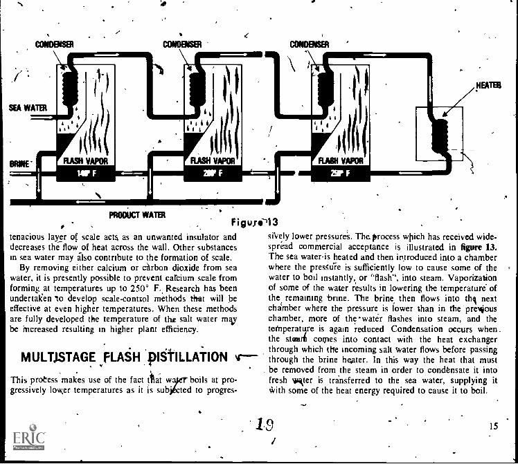
, . Figule13tenacious layer of scale acts as an unwanted insulator anddecreases the flow of heat across the wall. Other substancesin sea water may also contribute to the formation of scale.
By removing either calcium or carbon dioxide from seawater, it is presently possible to prevent carcium scale fromforming ,at temperatures up to 250° F. Research has beenundertaken 'to develop scale-control methods that will beeffective at even higher temperatures. When these methodsare fully developed the temperature of the salt water maybe increased resulting in higher plant efficiency.
srvely lower pressure's. The.process which has received wide-spread commercial acceptance is illustrated in figure 13.The sea water-is heated and then introduced into a chamberwhere the presSuTe k sufficiently low to cause some of thewater to boil instantly, or 'flash", into steam. Vaporizationof some of the water results in lowering the temperature" ofthe remaining 'brine. The brine, then flows into till nextchamber where the pressure is lower than in the'previouschamber, more of thewater flashes into steam, and thetemperature is again reduced Condensation occurs when_the steari comes into contact with the heat exchanger
, . through which the incoming salt Water flows before passing
..MULTISTAGE FLASH DISTILLATION 44"--- through the brine hexer. In this way the heat that must
4_ be removed from the steam in order to condensate it into
This process makes use of the fact itat w boils at pro- fresh loiter is transferred to the sea water, supplying itgressively low,er temperatures as it is sub' ted to progres- with some of the heat energy required to cause it to boil.
I15

VERTICAL TUB DISTILLATION
figure 14 indicates hoyv this process received its name.Thesalt "water falls through a bundle of vertical tubes locatedinside a large chamber. As tht salt Water falls through thetubes, it,is heated by steam that surrounds the tubes. Thisheat- exchange operation converts sow of the water fromthe saline solution inside the tubes into steam and at the,same time condenses some of the steam that surrounds thetubes into fresh water.
To obtain high efficiency in the recovery of heat energy,the process is repeated in several chambers which are ar-ranged in series. The steam for the first chamber is suppliedby a steam-generator plant, and the condensed water fromthe first chamber is returned to the steam-generator plantto be reconvektoti Into steam Steam generated inside thetubes of the first chamber flows to thd second chamberwhere it surrounds the second bundle of tubes. The brinethat'did not vaporize in the first chamber is pumped to the
16
HEATER
BRINE
1st EVAPORATOR
250' F. ilk1.111
SEA WATER INTAKE
STEAM
top of second chamber and flows dOwnward throughthe second tube bundle The steam that surrounds the tubesheats the brine as it falls, converting some of the water le-side of the tubes into steam, and condensing some of thesteam outside the tubes into fresh water.
This process is repeated through several chambers untilmost of the heat energy supplied in the first chamber is re-covered. The temperature of the saline water drops as itprogresses through the series of chambers. In an experi-mental plant at Freeport, Tex., the salt water entered thefirst chamber at 250° F and entered the twelfth, andchamber at approximately .90° F. Tfie pressure in eachchamber was also progressively reduced to psrmit vapor-ization to occur at lower temperatures, The brine that .
rn' collected.at the bottom of the last chamber was returnedto the sea.. Each separate chamber in which distillation occurscalled an "effect'''. Thus, this process is sometimes calledthe ".vertical tube, muitiple-effect distillation process'.
3rd EVAPORATOR2nd EVAPORATOR 42Ih EVAPORATOR
APPROX.
90° F.
WATER= LOW PRESSURE STEAM
Figure 14
20
BRINE TO SEA
FRESH WATER

I a
I STAGESHEAT REJECT
RECYCLE LOOP
21 STAGES
HEAT RECOVERY
3 STAGES ' OEAERATOR
HEAT REJECT
RECYCLE LOOP
loimmirmippmwmgmniwooaromiai sumsHEAT RECOVERY =OM
COOLANT OUTLET.
2 STAGESHEAT REJECT
IKET
ZO STAGES
HEAT RECOVERY
COIDENSATE
FIRST EFFECT SECOND EFFECT
Figure 15
. MULTIEFFECT MULTISTAGE
44 -4 ,,,,, DISTILLATJONThe multistage flash oCess discusied previously is alsodesignated,"SEMS", fo single-effect multistage". The mul-tieffect multistage (MEMS) process is an advancement overthe SEMS process. Up to a rim; the flash process becomesmore efficient as the number of,stages used for vaporiziniand preheating increases. The ava. able pressure diaitliceneeded to move the brine froM c mber to chamber at thelow-temperature, lour-pressure en of the cycle is the limit- *ing factor in the quantity of water circulated and the num-ber of stages that can be employed in a SEMS plant. Thetemperature changes are usually limited about 4° F. perstage, because of the low pressure differential available atthe bigh vacuum conditions that gist in the final few stages.The MEMS process makes it possible to add more stagesfor each temperature interval as pressure differences in-crease by breaking up the conventional single circulating
J
21
BRINE,
THIRD EFFECT
path into a number of circulat4sloops. The increasingcirculation rates in the higher temperature effects, combinedwith more stages in a given temperature interval, providegreater economy.
Separating the process into a number of effects, eachoperating at a different temperature,. permits better controlof scale. A multiple-effect unit separatekthe recirculationof brine and produces low brine concentr4on in the high-rmpeiature effects.
A diagram 'of the MEMS procIss is shown in figure 15.The salt water is preheated in two stages and is then treatedwith acid to prevent the precipitation of scale from the feedsalt water. Preheating continues through a number of stagesuntil the first effect is reached. From the first effect, someof the brine s recirculated through the brine eater, andsome is passed to the second effect. Thepartial recircula-tion and paitial progression to succeeding stages continuesuntil the final effect, where the highly concentrated brineis either discharged or passed to a byproduct-recovery unit.
17

VAPOR COMPRESSION DISTILLATIONWhen a r is compresled, its temperature and pressureincrease and its volume decreases.
In each effect, brine is pumped upward through a tubebundle into a large spherical chamber. As the brine travelsupwjd, it is heated by the steam that'surrounds the tubes.ThRtransfer of heat causes some of the water to vaporizeafter it leaves the tuM A mixture of vapor and brine entersthe spherical chamber. Some of the brine is returned to thebottom of the tube bundle and recirculated, some of thebrine is discharged The vapor from the second effect, whichis on the right in figure 16;is drawn off by 'the compressorand the higher temperature vapor that leaves the comprq-sor is transferred to the first effect. The vapor ditchargedftiom the compressor surrounds the tube bundle in the firstreffect, and supplies heat to the brine that`: is traveling up-
-
18
ward in the tubes. The vapor that forms in the sphericalchamber in the first effect is transferred to the second ef-fect where it supplies heat to the brine that is being pumpedthrough the second-effect tube bundle. As the vapor in botheffects loses heat to the brine. some of the vapor condenses.The condensate falls to the bottom of the effects and ispumped off as product water.
, The primary difference between this process, and other .
distillation processes is in the method by which heat isadded to the system In other processes, saline water ishe4d v,)ith steam in order to cause some of it to boil. Inthis process, however, heat is added"to the. vapor by con-verting mechanical work into heat of comprzssion.
Most of the energy is consumed by the motor that drivesthe compressor. Steam heat is added directly only during
sfartup
PRODUCT WAITE
Figure 16-SECOND EFFECT

Preconditionidg
In addition to the main processing equipment, auxiliaryequipment is used to treat incoming salt water before itenters the evaporators. In the auxiliary prOcessing steps,'chemicals are mixed with the salt water to prevent forma-tion of scale on\the heat-transfer surfaces. The salt wateralso passes thro6gh heat exchanger, before it enters thetubes. The brine that is being discharged and the productwater are used-to preheat the incoming salt water. By pre-'heating in this manner, the salt water is raised almost tothe boiling temperature before it reaches the evaporator,and the product water leaves the system at a temperaturethat is only about 15' F. above the temperature of the in-coming salt water. -
SOLAR HUMIDIFICATION.. ,
The solar-humidification process makes use of the fact thatwater will evaporate from a free -surface, even though thewater is at a temperature belqw its boiling point. The rateof evaporation of the water depends largely on two factorthe temperature of the water and the relative humidity ithe space above the free surface of the water. The conVer-sion process takes place in an. apparatus called a solar still.The operation, of a solar still is illustrated in figure 17. Asolar still utilizes the same principles that keep a green-house warm on winter days. The sun's rays pass throughthe glass top without" giving up any significant amount ofenergy. The sun's energy is absorbed by the black surfaceon thlbottom of the still. The temperature of the water inconta with the heated black surface increases, and thewater evaporates.
Because the glass top of the solar still is not heated ky ..rSLACK SURFACE
. Figure 17.
io
FRESH WATER
19

I
the sun's rays as !Mich as the black surface, the temperatureof the top remains lower than that of the vapor. Because ofthis temperature difference, the water vapor that comes incontact with the fop condenses and runs down into thecollecting trough. As some of the vapor is removed fromthe space above the water surface by condensation, the rela-tive humidity decreases, tending. to increase the- rate ofevaporation
Conversion rateThe obvious advantage of this process is that the energy
required for' conversion is free. Furthermore, labor andmaintenance are minimal HoweVer, the-disadvantages areequally obvious. The conversion rate depends on the inter[-say of the sun's rays, which varies according to geography
ical location, time of year, and the extent of cloudines.'fog, or haze Even under ideal solar-transmission conditions,only about I pint of fresh water can be obtained each dayfor each square foot of surface that absorbs the solarenergy
T,he evaporation rate depends on the depth of the waterbeing heated by ,tle absorbing surface. Because the rate of
s,
20 7
evaporation depends also on relative humidity, t conver-sion rate is highest when the temperature of the lass topis lowest, because at low temperature condensation occursmore rapidly
Even though the conversion energy is free, efficiency isan important. factor in solar humidification because or therelationship between surface area and conversion quantity.
When' solar energy contacts any surface., the energydivides in three ways. Some of the energy is absorbed bythe some is reflected away, and some is transmittedthrough the surface. Black surfaces absorlythe most energy,white or polished metal surfaces reflect the most energy,and transparent surfaces transmit the most ,energy. Thus,selection of materials is important not only from a cost ofmaterials standpoint but also from a sfrandpoint of utilization of solar energy, which determines the efficiency of sur-face utilization. Insulation is often used to reduce heatlosses into fhe ground. For shallow basin stills, which op-erate at relatively high temperatures,, insulation is an im-portant consideration in obtaining economic advantages.All joints must be carefully sealed to prevent escape of theheated vapor.
24
CRYNALLIZATIONr
IT IS WELL KklOVV,N THAT a salt solution cooled to itsfreezing temperature will deposit ice crystals of pure water.This principle forms the basis for desalting water by thefreezing process.i
Heat of Fusion
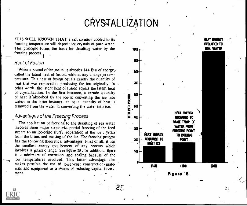
When a pound of -ice melts, it absorbs 144 Btu of energy,-called the latent heat of fusion, without any changejn tem-perature, This heat of fusion equals exactly the quantity ofheat that was removed in producing the ice originally. Inother words, the latent heat of fusion equals the latent heatof crystallization. In the first instance, a certain quantityof heat is'absorbed by the ice in converting the ice intowater; in the latter instance, an equal quantity of heat isremoved from the water in converting the water into ice. 500
Advantages of the Freezing Process 1 400
The application of freezing*
to the desalting of sea waterinvolves three major steps: viz, partial freezing of the feedstream to an ice-brine slurry, separation of the ice crystalsfrom the brine, and melting of the ice. The freezing processhas the following theoretical advantages: First of all, it hasthe smallest energy requirement of any process whichinvolves a phase-change. See figure 18 In addition, thereis a minimum -of corrosion and scaling because of thelow temperatures involved. This latter advantage alsomakes possible the use of lower-cost construction mate-rials and equipment as a means of reducing capital invest-ment. . -
1000
900
800
700
MO
I"LI
MO
200
WO
0
I
HEAT ENERGY
MEW TOMELT ICE
.HEAT ENERGY
REOUIRED TO
RAISE TB/P. OF
WATER FROM
FREIMING PONT
TO BOILING
POINT -
HEAT ENERGY
REQUIRED TO
OK WATER
ON OE
Figure 18
MIN
21

AIR BUT
SFA jltWATER E
k FRESHal""°' R WATER
E
A
.
MR REMOVAL
.
FRESH WASH WATER IN r
ICE
iHEAT ,
EXCHANGER' KAILIII
WASTE BRINE,
.-/ . . UNIT V,'-,-,
1 54
1
REFRIGERATION
SEA WATER
BRINE
FRESH WATER'
)
22
, ,
N
-BRINE
SLURRY
11111311000NVEITTER
. *F ii; re 19
26 t
1
i
COUNTERWASHER
0
SCREENS

To preserve the inherent economic advantages of freez-ing, .direct contact methods. of refrigeration are employed;the 'need for expensive heat-transfer surrices for heat re-moval, or recovery is therefore avoided.,
Variations of the Freezing Pr. essFreezing may be accomplished b the flash evaporation
.9f sea water at a low pressure (3 mm g) of by vaporizinga refrigerant such as butane in direc ontact with the seawater. The process variations are, described in the)91low-mg sections.
VACUUM Ir6ING-VAPOR, COMPRESSION
4.1n the vacuum, freezing-vapor compression processP thelatent heat of fusiOn is given up when precooled sea wateris introduced into a chamber at a very low pressure. Anadvantage of the process is that no cooling medium orheat-transfer surfaces are used to accomplish freezing. Theprocess is illustrated in figure 19. -The sea water is pastedthrough a dearator to remove* air and noncondensablegases. The,deaerated water is then cooled by heat exchangewith the product-water and waste-brine streams. This cold,deaerated sea water is then introduced into the lower sec-
on.of the chamber,. known as the hydroconverter, whichis maintained at a low pressure (3 mm Hg). This lowpres-sure causes a portion of the water to vaporize, thus re-moving heat from' the sea water. Approximately one-halfof the sea water is frozen into ice crystals.
the mixture of ice crystals and brine, Called a slurry,is pumped to the bottom of a separation column, or coun-terwasher. The slurry rises within the column anl the ice
111
27
crystals are compacted to form a porous bed of ice. Thebed is moved upward by a slight positive. pressure causedby the brine flowing through the bed and outward throughscreens positioned approximately at the middle of the col -umn. The rising ice re'ci- is washed countercurrently with,less than 5 percent of the total fres water product of theplant. The ice is then remoyed by m ans of a mechanicalscraper at the top of the kceumn, a d the scrapings aredumped into the melter, or upper section of the hydrocon-verter.
When sea water enters, the lower section of the hydro-converter, some of the water1flashes t6 a vapor. Thisvapor is then compressed by a specially designed com-pressor located at the top of the hydroconverter. Thecompressed vopor is then condensed on the washed iceentering the melter, or upper sectiou. of the hydrocon-verter. Because the compressed vapor contains the heatoriginally removed from the Sea water in the freeze*the s melted to fresh water. Waste brine from the washc mn and product water from the melter are dischargedfTm t process, one to waste disposal and the other, tothe umer.
SECONDARY REFRIGERANT FREEZING
The secondary-refrigerant freezing process differs from thevacuum-freezing process principally in the met* by whichfreezing is accomplished. In the former method a refrig-erant, such as butane, is evaporated in direct contact withthe sea water to remove the latent heat of crystallization(144 Btu/lb) in order to partially freeze the sea water.
The process is illustrated in figure 20. Sea water is pre-cooled by heat exchange with the product-water and waste-brine streams. The sea water enters the freezer where liquid
23
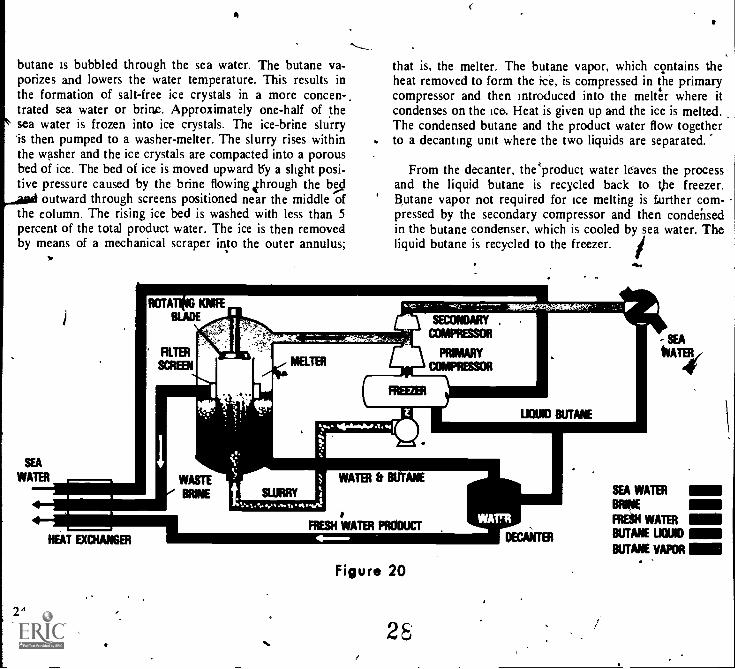
butane is bubbled through the sea water. The butane va-porizes and lowers the water temperature. This results inthe formation of salt-free ice crystals in a more concen-.trated sea water or brine. Approximately one-half of thesea water is frozen into ice crystals. The ice-brine slurry'is then pumped to a washer-melter. The slurry rises withinthe washer and the ice crystals are compacted into a porousbed of ice. The bed of ice is moved upward 15y a slight posi-tive pressure caused by the brine flowing Through the bed
outward through screens positioned near the middle ofthe column. The rising ice bed is washed with less than 5percent of the total product water. The ice is then removedby means of a mechanical scraper into the outer annulus;
that is, the melter. The butane vapor, which contains theheat removed to form the ice, is compressed in the primarycompressor and then introduced into the melter where itcondenses on the ice. Heat is given up and the ice is melted.The condensed butane and the product water flow togetherto a decanting unit where the two liquids are separated.
From the decanter, the'product water leaves the processand the liquid butane is recycled back to the freezer.Butane vapor not required for ice melting is Luther com-pressed by the secondary compressor and then condensedin the butane condenser, which is cooled by sea water. Theliquid butane is recycled to the freezer.
24
Figure 20
28
SEA WATER
BRINE
FRESH WATER
BUTANE UOUID
BUTANE VAPOR

Q
EUTECTIC FREEZING
When the freezing process is operated to increase the brineconcentrationjn the freezer, a point is eventually reached,where both ialP crystals and salt crystals .are formednul-taneously. At that point the concentration of disc f: led
solids and therefore the freezing point of the solution re-main constant. Operation of a freeze desalting processudder these conditions' has been termed ",eutectic freezing".Using sodium chloride as an exargple, the eutectic freezingpoint would be 6° F. at a constant co' centration of 23.3percent dissolved solids.
It has been found to be technically feasible to continu-ously separate ice and salt crystals individually from thebrine thereby reducing the effluent steins from the desalt-ing plant to fresh water and wet salt. The secondary refrig-erant type process would normally be used for .eutecticfreezing with at least two stages of frfezing to reduce powerconsumption. The low temperature eutectic stage freezerwould require a mere powerful iefrigeraitt compressor be-cause of the large temperature difference between the
`'freezer (-6° F.) and the melter (32° F.). The bulk of thefresh water product.wOuld, therefore be produced from afirst stage freezer operating at a lower, brine concentrationand correspondingly higher freezing temperature. '
HYDRATE FORMATION
The hydrate process is based on the formation of a crystal-line substance by the combination of low-molecular-weighthydrockbons or their derivatives with water. The resultingcrystalline compounds are known generally as solid cla-thrate substances. Specifically, a clathrate is an inclusion
1--
I,1
2
Figure 21
3 4 $
I I 'I
complex in which the molecules of substance are con-tained or enclosed within th rystal lattice of anothercomponent. ,Like ice crystals clathrate hydrates reject saltions and water molecules enclose a guest,. bydrocartfon,within their lattice (Fig. 21).
29 25

In the hydrate process, sea water and a hydrating agentsuch' as propane are brought into intimate contact in avcrystallizr When, the,, temperature and- pressure are ad-justed to" oiler levels, hydrate crystals form. The,crystalsare separated from the brine and then washed with smallportion of fresh water. This step is accomplished irkaves-sel-known as a wash-separator. The crystals in slurry formare pumped to the melter-condenser where they are de-composed by melting. he latter step is accomplished bycondensing compressed ropane vapor on Ike crystals, thusproviding the neces heat to melt the crystals. Becausepropane is insoluable 'iii water, two immiscible .liquids(water and propane) tesult when the hydrate crystals aremelted. The two hip have different densities and thtre-fore may be separate, in much the same way that %Vaterand oil are separated. viz, by decantation. The two liquids
r
26
are collected in the decanting vessel, the propane separat-ing out and floating on top of the water layer. The wateris drawn off into a suitable storage container, and the liquidpropane is pumped back to the crystallizer to continue theprocess of hydrate formation. As is evident, the operationalsteps involved in the hydrate process are basically the sameas those used_in_the_secondary-rekigerant free'zing process.Therefore, an individual Pow ditgram has not been in-cluded for the hydrate process..
An ideal hydrating agent would be nontoxic, nonflam-mable, available in large quantities at low cost, and wouldnot impart an objectionable taste to the product water.Fundamentally, it is also desirable that the crystals have alow heat of fusion so that decomposition may be accom-plished with relatively little energy exchange.
30

CHEMICAL PROCESSES'SALINE WATER MAY BE SEP TED into purewater and salt or concentrated brine chemical methods.Either the salts or the water may be made' to undergo achemical,reaction to form a substance thatireadily sepa-rated.
In the ion-exchange process the salts react with speciallyfermulated resins that are reactive but insoluble. One kiof resin takes up sodium ions and other cations and telea
/ hydrogen ions. A second type of resin takes up chlorideions 'and other anions and releases hydroxyl ions. Thehydrogen ions and hydroxyl ions combine to form small
imounts of water. The original saline water is deionized,that is. it freed of dissolved salts.
ION EXCHANGE.
n ion exchanfer lea porous bed of certain resin materialsthat have the ability to exchange ions held in the resin with..
those in a solution that contacts the bed. Minerals andiesins are available which exchange ions with either cationsor, anions. Inthe former case, the process is called cation-exchange, and in .the latter case, anion exchange. When asolution containing cations is passed through a cation ex-changer, the cations from the solution are exchanged withcations from the bed material: The cations from the in-coming solutions remain bound to the exchanger, and thosefrom the bed material leave With the outgoing solution: Asimilar exchange of anions occurs in flow through an anionexchanger. . ,
Numerous substances of both natural and synthetic or- 'igin possess ion-exchanging properties. The materials of in-4 .,,
-J
Figure 22terest in saline water conversion are synthetic resins. The.synthetic resins are plastics chemically prepared for specificion-exchange properties.
In the ion-exchange conversion process, both cation andanion exchangers are used. The ion-exchange beds are us-
31.27 .

"ually placed in series, although mixed feeds may be used,and the saline solution passes first tIhrough the cation ex-changer and then through the anion exchanger. An exampleof the ion-exchange process is illustrated.in figure 22. Thecatron exchagger is an acidic resin that exchanges its hy-drogen ions for the sodium ions in the incoming solution.The., anion exchanger is a basic resin that exchanges its OH-'Ohs for the chloride ions in the solution. The OH- ion isalle4 the hydroxide ion. In the arrangement shown in fig-
ure 14;Th saline solution corv,aining. sodium and chlorideions enterf at the top of the conversion unit. -
When the solution contacts the cation exchanger, thesodium ions are exchanged for the hydrogen ion, and thechloride ions pass through unaffected. Thus, the sodiumchloride solution is converted into a gOlution of hydrogenand chloride ions, which is actually a dilute solution ofhydrochloric acid. As the acid solution flows through the
*VP
28
32
anion exchanger the chloride ions are exchanged for hy-droxide ions When the hydroxide ions are released, theycombine with the hydrogen ions, forming molecules ofpure water.
As the conversion process continues, the resins are pro-gre,ssively saturated until finally they lose their ability toremove sodium or chloride 'ions. When \ this point isreached, the. conversion process must be hdlted while theresins are regenerated. Regeneration is accomplished bywashing the resin beds with acids or bases that restore theoriginal ion-exchange properties to the exchangers.
Regeneration costs have limited ion exchange to applic-a-tions where salts are in low concentrations, less than 2-3000mg I. The process can be used to obtain small amounts offresh water from sea water'in cases where energy sourcesare not available. Emergency 'kits for liferafts are one ex-ample of this application..

,
SALINE WATER CONVERSION PLANTSTEST PROGRAMS have been conducted for each of thesaline-water conversion processes discussed above. Someof the processes have been tested on a laboratory scale, andsome have adyanced to the test-bed-plant stage.'The ob-jective of the testing has been to obtain information on thechemical and physical feasibility of various processes. Theobjective of the test-bed-plant operations, has been td obtainand confirm information on equipment design and operat-ing procedures for application to large-scale conversionplants.
Experience to date indicates thatthere is a need for anumber of conversion processes. Factors such as type andquantity of available energy, production capacity required,and concentration of feed water alLtombine to determinewhich process is 'the most suitable and economical for agiven geographical location.
Dual-Pqrpose PlantsCombining saline water conversion' with electric-power
generation shows promise as let econonfiical method ofproducing large quantities of fresh water. in a dual-purposeplant the heat energy that remains in the steam qtter itpasses through a steam turbine is used as the heat-sourcefpr a distillation conversion process. High-temperature,
-00r '
t,
high-pressure steafn is used to power a turbine that drivesan electric generator. The turbine exhaust steam is fed toA saline-Water conversion plant where it condenses as itgives up more of its heat energy, and the condensate isthen returned to the steam generator. .
,Tripurpose PlantsWhen the capacity of the saline water conversion unit
is relatively high, a third function, byproduct recovery, maybe incorporated in the plant with improved overall econ-omy.,in a tripurpose plant, 'the brine is routed to a by-product-recovery unit where minerals of significantconcentrations with commercial value are extracted. Thethree minerals of greatestseconotnic p-Otefitiallein sea water(excluding fresh water) are salt,inagnesia, and potash. Onesea water desalination plant producing 50 gallonspet, day of fresh water and operating at a brine s tra-tion faCtor of 3:1 could also produce about 20 pe t ofthe U.S. annual salt requirements, 25 percent s mag-nesia, and 1 percent of the gotash. More salt and magnesiacould be produced than utilized at a given location; how-ever, this is not true for potash. The' plant could produce150 tons per day of potash (W) which would have avalue of $6,000v$10,000 depending on whether it wasrecovered as the chloride or sulfate.
29

DESALTINGAPPLICATIONS '
,
DESALTING PLANTS INVENTORY REPORT NO.5*, prepared for the Office of Water Research and Tech-nology by the National Water Supply Improvement Asso-biation, provides the following data for land based desaltingplants in operation or under construction of 25,000 gallonsper dgy or larger as of January 1, 1975.
PLANTCAPACITYMILLION
f* NUMBER GALLONSREGION OF PLANTS PER DAY
United States and territories 372. 88 ANorth America (except U.S. 41 12South America & Caribbean 63 38Europe 218 84Africa 104 57Arabian -Peninsula Iran 153 146Asia & Indon 68 68Australia and 10 2Union of Sovi
Republics 7 301036 525
This publication may be chased through WIS. Springfield,Virginia Order number PB 3556
30 34* U.S. 07/1111111UNT PIENTIINI OFFICII !HIV 0-24121
,.-
.
t
1.

I
GLOSSARYAnion - -a negatively charged ion.
Brackish waterwater ranging from 1,000 to 35,000 partsper million of total dissolved solids.,
Briaeany concentrated water solution containing dis-solved salts.
Cadoaa positively charged ion.Corrosiona chemical attack on a metallic surface, often
causing a structural weakening of the metal.EleciA process such as distillation may be performed at
one temperature and pressure or it may be. performedin a series of steps at graduated temperatures. Each com-plete step in such a process is called an effect.
Fresh wrierwater containing less than 500 parts of dis-solved salts per million parts of water. Water containingmore than 1000 parts of dissolved salts per million partsof water should pot be used for human consumption.
Hest of fusion--* amount of heat which must be addedto unit mass of a solid substance as its melting point toconvert- the substance into liquid at the same tempera-ture and pressure..
I
Heat of vaporizationthe' amount of heat which must 1 ieadded to a liquid at its bOiling point in order to convertthe suilstance into vapor at ,the- same temperature andpress e.
Hydratea crystallized substance formed by the ocia-tion of water molecules with certain chemical compo ds.
loaan electrically charged atom or group of atoms.Membrane -4 thin sheet of plastic ,or other material. If
has the ability to permit certain substances to palsthrough it and exclude others, it is called a semipermeablemembrane.
Osmosisthe diffusion through a semipermeable mem-brane separating two solutions which tendi to equalizethe concentration of the solutions.
Saline waterbrackish water, sea water, or brine, contain-ing more than 1,000 ppm of total dissolyed solids.
Scalea 'hard incrustation that( forms inside a vessel inwhich water is heated. SCale is objectionable because itreduces heat transfer.
Stagea part of a process which is being undertaken inprogressive similar steps.
35