The hydraulic jump in circular jet impingement and in other thin - MIT
9
Experiments in Fluids 15, 108-116 (1993) Exl riments in Fluids Springer-Verlag 1993 The hydraulic jump in circular jet impingement and in other thin liquid films X. Liu, J. H. Lienhard V Department of Mechanical Engineering, Massachusetts Institute of Technology, Cambridge, MA 02139 USA Received: 8 September 1992/Accepted: 1 March 1993 Abstract. The circular hydraulic jump exhibits behavior quite differ- ent from that commonly observed in planar jumps. Here we examine experimentally some of the causes and consequences of those differ- ences. We suggest that surface tension plays a dominant role in establishing the shape of the circular jump for impinging jets. The importance of surface tension is a direct result of the thinness of the liquid films normally encountered in circular jump configurations. A sequence of instabilities appears in the jump's structure as the subcritical liquid film becomes thicker and surface tension effects decrease. These conclusions are corroborated by experiments on thin planar films which result in unusual jump structures, like those seen in circular jumps. In addition, we show that the standard momentum balance for the circular jump is effective only at relative- ly low supercritical Froude numbers or at low ratios of downstream to upstream depth. Typical values of those parameters for circular jumps are often quite large relative to the usual values for planar open-channel flows. List of Symbols d jet diameter D fictitious downstream drag force Era jet Froude number, us/xf~ Frh supercritical film Froude number, uyd2/8rjx/~ 3 Fr~ subcritical film Froude number, ufd2/8rsx~ g gravitational body force h local thickness of liquid sheet p hydrostatic pressure r radius measured from jet stagnation point rj radius at which hydraulic jump begins r~ radius at which subcritical depth equals s R radius of curvature of jump interface Red Reynolds number of the jet, usd/v. s liquid sheet thickness after hydraulic jump u(r,y) radial velocity distribution in liquid film uy velocity of impinging jet tih depth average velocity for sheet of thickness h, usd2/8rh y distance normal to the wall We Weber number of jump, sx/pg/a Greek letters v liquid kinematic viscosity p liquid density ~r surface tension 1 Introduction Jet impingement cooling systems sometimes operate with a hydraulic jump downstream of the region of impinge- ment (Fig. 1). The slow-moving liquid in the sub-critical region presents degraded heat transfer characteristics, which makes prediction and control of the jump location important in thermal design. This paper examines the difficulties that have been found in using simple jump theory to predict the jump's radial location in jet impinge- ment. The open-channel hydraulic jump of undergraduate textbooks is usually manifested as a roiling turbulent free surface connecting the supercritical and subcritical re- gions of the flow. For plarrar flow, application of a one-dimensional momentum balance describes the rela- tionship between upstream and downstream depth and velocity with an accuracy of about 1% over conditions ranging from laboratory flumes to hydroelectric power plants (Peterka, 1963). In such situations the jump prob- lem is both classical and well understood. In contrast, Fig. 1 shows a liquid surface that is very smooth, with a sharply defined and relatively steady hy- draulic jump. In addition, the upstream (supercritical) liquid film is very thin, with a minimum thickness of about 100 tam for the 5 mm diameter jet shown. Apart from these obvious differences in flow field, this jump differs from the usual open channel jump by the range of the supercritical Froude number. For the impinging jet, the upstream Froude number can be as much as several hundred, while typical open-channel flows have supercritical Froude numbers of no more than 20 or 30. Each of these factors contributes to unexpected deviations from the standard theory of the hydraulic jump. 1.1 Experimental tests of the theory Direct adaptation of the momentum balance theory to impinging jet jumps was first made by Watson (1964), and
Transcript of The hydraulic jump in circular jet impingement and in other thin - MIT

Experiments in Fluids 15, 108-116 (1993)
Exl riments in Fluids �9 Springer-Verlag 1993
The hydraulic jump in circular jet impingement and in other thin liquid films
X. Liu, J. H. Lienhard V
Department of Mechanical Engineering, Massachusetts Institute of Technology, Cambridge, MA 02139 USA
Received: 8 September 1992/Accepted: 1 March 1993
Abstract. The circular hydraulic jump exhibits behavior quite differ- ent from that commonly observed in planar jumps. Here we examine experimentally some of the causes and consequences of those differ- ences. We suggest that surface tension plays a dominant role in establishing the shape of the circular jump for impinging jets. The importance of surface tension is a direct result of the thinness of the liquid films normally encountered in circular jump configurations. A sequence of instabilities appears in the jump's structure as the subcritical liquid film becomes thicker and surface tension effects decrease. These conclusions are corroborated by experiments on thin planar films which result in unusual jump structures, like those seen in circular jumps. In addition, we show that the standard momentum balance for the circular jump is effective only at relative- ly low supercritical Froude numbers or at low ratios of downstream to upstream depth. Typical values of those parameters for circular jumps are often quite large relative to the usual values for planar open-channel flows.
List of Symbols
d jet diameter D fictitious downstream drag force Era jet Froude number, us/xf~ Frh supercritical film Froude number, uyd2/8rjx/~ 3 Fr~ subcritical film Froude number, ufd2/8rsx~ g gravitational body force h local thickness of liquid sheet p hydrostatic pressure r radius measured from jet stagnation point rj radius at which hydraulic jump begins r~ radius at which subcritical depth equals s R radius of curvature of jump interface Re d Reynolds number of the jet, usd/v. s liquid sheet thickness after hydraulic jump u(r,y) radial velocity distribution in liquid film uy velocity of impinging jet ti h depth average velocity for sheet of thickness h, usd2/8rh y distance normal to the w a l l We Weber number of jump, sx/pg/a
Greek letters
v liquid kinematic viscosity p liquid density ~r surface tension
1 Introduction
Jet impingement cooling systems sometimes operate with a hydraulic jump downstream of the region of impinge- ment (Fig. 1). The slow-moving liquid in the sub-critical region presents degraded heat transfer characteristics, which makes prediction and control of the jump location impor tant in thermal design. This paper examines the difficulties that have been found in using simple jump theory to predict the jump's radial location in jet impinge- ment.
The open-channel hydraulic j ump of undergraduate textbooks is usually manifested as a roiling turbulent free surface connecting the supercritical and subcritical re- gions of the flow. For plarrar flow, application of a one-dimensional momen tum balance describes the rela- t ionship between upstream and downstream depth and velocity with an accuracy of about 1% over conditions ranging from laboratory flumes to hydroelectric power plants (Peterka, 1963). In such situations the jump prob- lem is both classical and well understood.
In contrast, Fig. 1 shows a liquid surface that is very smooth, with a sharply defined and relatively steady hy- draulic jump. In addition, the upstream (supercritical) liquid film is very thin, with a minimum thickness of about 100 tam for the 5 mm diameter jet shown. Apar t from these obvious differences in flow field, this j ump differs from the usual open channel j ump by the range of the supercritical Froude number. For the impinging jet, the upstream Froude number can be as much as several hundred, while typical open-channel flows have supercritical Froude numbers of no more than 20 or 30. Each of these factors contributes to unexpected deviations from the standard theory of the hydraulic jump.
1.1 Experimental tests of the theory
Direct adapta t ion of the m o m e n t u m balance theory to impinging jet jumps was first made by Watson (1964), and

109
Fig. 1. Hydraulic jump for an impinging jet: Single-roller condition, d=4.96 ram, rj=4.78 cm, Red,~22000.
several subsequent investigators modified his theory slightly; the basic result is generally a prediction of the radial position of the jump. Experimental tests of these models, however, have not been entirely satisfactory. Wat- son himself presented data showing both good agreement and relatively poor agreement, and subsequent compari- sons have been numerous: Olsson and Turkdogan (1966), Ishigai et al. (1977), Nakoryakov et al. (1978), Bouhadef (1978), Craik et al. (1981), Errico (1986), and Vasista (1989) have each tested Watson's model. Some of these investiga- tions have reported rough agreement with the model, some have found good agreement for a limited range of parameters, and others have found relatively poor agree- ment. Craik et al., for example, reported that Watson's model works best when the jump radius is more than ten times the supercritical depth, with larger disagreements for smaller radii. Errico's data often showed poor agree- ment with Watson's prediction, an effect he attributed to his own lower flow rates (thus smaller jump radii) and deeper jumps. Vasista's measurements showed increasing- ly poor agreement with Watson's model as downstream depth increased and as jet diameter increased. These studies did not systematically vary dimensionless groups, and most do not clearly distinguish an upstream Froude number. However, to focus on the trends of disagreement, we note that decreasing the jump radius and increasing the jet diameter both tend to raise the supercritical Froude number by supplying faster moving liquid to the jump. We surmise that Watson's model is less accurate when the downstream flow is too deep or when the upstream Froude number is too high.
A clue to the cause of this behavior lies in the velocity profile behind the jump. The experimental studies have shown that the flow just behind the jump can separate,
creating a recirculating eddy attached to the wall. This separation is a result of the abrupt increase in hydrostatic pressure at the jump, an effect that is clearly worsened when the downstream flow is deeper. Measurements by Errico (1986) and by Craik et al. (1981) show that the separated region can be quite long and that its length changes significantly with flow conditions. Further, the supercritical film is deflected upwards and travels over the separated region while maintaining a high speed. Clearly, the complex flow field behind the jump has a serious effect on any one-dimensional momentum conservation model. Velocity profile effects thus account for some of the dis- agreements reported.
A second complication is that the shape of the jump surface has been observed to have several forms, variously being smooth, curved, showing standing or radiating waves, and showing outright instability (the latter being reminiscent of the usual open channel jump). The para- meters reported to be responsible for these changes in- clude increasing downstream depth (Craik et al., 1981), increasing volume flow (Errico, 1986; Thomas et al., 1991), and increasing upstream Froude number (Ishigai et al.,' 1977). Typically, the changes reported are described as some form of instability in the smooth free surface of Fig. 1. These successive changes in the jump surface have a controlling influence on the velocity profile beyond the jump and may affect the breakdown of the jump radius
' predictions. In this light, previous studies have generally concluded
that the failure of the standard jump momentum balance results from the nonuniform velocity profile and perhaps from the presence of wall drag beneath the jump. These factors are clearly linked to the shape and stability of the jump interface, but the latter have generally been implied to be primarily a property of the axisymmetric geometry. Apart from the apparent Froude number dependence reported by lshigai et al., no consideration has been given to the variables that control the stability of the jump surface.
Our purpose hereinafter is to describe new experi- mental results on the stability of the jump's free surface. We argue that the stability is primarily dependent on the liquid surface tension, which can play a significant role only when the subcritical fluid layer is relatively thin. The thinness of the downstream flow is a condition that has seldom been met in planar jump experiments but which is a regular feature of axisymmetric hydraulic jumps, even those that are described as deep in the preceding dis- cussion. In addition, our data show that a large super- critical Froude number (or equivalently a large ratio of downstream to upstream depth) is the other key factor in the failure of standard jump theory as applied to the circular jump. Both observations show that the thinness of the upstream and downstream films, rather than axisym- metry per se, is responsible for the failure of one-

110
dimensional theories of the jump. This conclusion is cor- roborated by an experiment on a thin planar film.
1.2 Predictions based on the momentum theorem Knowledge of the upstream and downstream flow vari- ations together with control volume mass and momentum conservation are sufficient for predicting the jump radius, provided that: (i) the wall drag in the region beneath the jump can be neglected; and (ii) the flow exiting the control volume satisfies the one-dimensional or uniform velocity profile usually assumed (Watson, 1964). The momentum balance is merely an extension of that for plane flow:
2nrj(flhpu(rj, y)2dy+ ; p dy)
=2rrr~(ffpu(r, y) 2dy+ ffp dy) (1)
where the terms are as shown in Fig. 2 and in the list of symbols. One particular feature of this balance is that viscous drag steadily slows the thin upstream film, causing the supercritical thickness and velocity profile to vary strongly with the radius and the jet Reynolds number. Thus, the supercritical Froude number is a strongly de- creasing function of radius, and the lefthand side of Eq. 1 is strongly dependent on Reynolds number and jump radius, r j.
Equation 1 was evaluated in dimensional form by Watson (1964) who used his solutions for the supercritical velocity distribution to obtain equations for the jump radius. Subsequent investigators have used other profiles or procedures (e.g. Bouhadef, 1978), but all models express the same general dependence of the jump position on upstream Reynolds and Froude numbers and a down- stream Froude number or depth.
We may cast these results into the form of classical jump theory by defining the supercritical Froude number at radius rj just ahead of the jump as:
tih (2) F r h -- ~ - h
where h is the film thickness and/~h is the average velocity
h [
rj . ~ D - - - - ~
F- rs ~
Fig. 2. Control volume and terminology for the jump momentum balance.
1 f~ l l fd 2 Uh = ~ u(rj, y) dy = 8r~h (3)
Assuming that the outflow velocity is also unidirectional and neglecting curvature effects in the jump region, mass and momentum conservation lead to the following equa- tion for the ratio of downstream to upstream depth:
s 1 . ~ = -~ (~/1 + 8 Fr~ - 1) (4)
The various circular jump formulae proposed by previous investigators, including Watson, can generally be ex- pressed by the above equation, apart from minor vari- ations related to the assumed velocity distributions and the method of calculating the supercritical liquid sheet thickness.
2 Experiments
Experiments were performed using both laminar imping- ing water jets and thin planar water films. In each case, an obstruction was introduced downstream to create a sub- critical region and, thus, a hydraulic jump.
The circular jets issued vertically downward from a small sharp-edged orifice at the base of a large plenum. Such orifices produce a uniform velocity profile across the jet a few diameters beyond the orifice. The plenum flow was carefully damped with honeycomb near the inlet to ensure that the jets were laminar. The main components of the apparatus are a water reservoir, a pump, the plenum, and a target plate in which the jumps were formed. Water is pumped from the reservoir to the pressurized plenum from which it exits as a free jet. The jet strikes the target plate normally and flows radially outward and over the plate's edge. The flow rates were varied by adjusting two globe valves on the supply line; the flow rate was deter- mined from the pressure in the plenum and the orifice discharge coefficient (taken as 0.611). The brass orifice plates at the lower end of the plenum are interchangeable; orifice diameters of 3.2 mm and 6.3 mm were used along with a plenum of 152 mm diameter. Further details of this apparatus are given by Vasista (1989).
The target plate was supported on adjustable screws that allowed the target to be horizontally levelled so that an even, axisymmetric flow was obtained. The target was a circular aluminium plate of 1.9cm thickness and 30.5 cm outer diameter. A 29.8 cm diameter circular de- pression was milled into the center of the plate, leaving an outer lip with a height of 1.3 cm. Circular plexiglas sheets of various thicknesses were inserted into the depression to vary the effective lip height, thus allowing the subcritical (downstream) depth of the jumps to be varied. The liquid depths were determined by using a micrometer point gauge. The radial position of the jump was measured from radial graduations on the target plate's surface.

Each test consisted of recording the pressure, the liquid thickness ups t ream and downs t ream of the jump, the j u m p radius, the insert height, the orifice size, and the distance from the orifice to the plate. In addit ion, the j u m p surface condi t ion was noted. The measured values are shown in Tables 1, 2, and 3.
Some tests were also conducted using a surfactant (detergent) to reduce the surface tension of the water. The resulting surface tension was measured using a ring gauge. ' The results of these tests are given in Tables 4 and 5.
The p lanar jet experiment used a cons tant head tank to supply water to a cylindrical p lenum having a horizon- tal axis. One endplate of the p lenum included a rectangu- lar slot; at the lower edge of the slot, a rectangular plexiglas sheet extended horizontal ly from the p lenum perpendicular to the end plate. An adjustable gate cover- ing the upper edge of the slot allowed variat ion of the height of the gap above the plexiglas sheet. Water issued through this gap as a thin p lanar film that flowed along the upper surface of the plexiglas sheet. Rectangular obst ruct ions were placed downst ream on the sheet to produce hydraulic j umps in the water films. Ensur ing two- d imens ional flow along the sheet required several pre-
Table 1. Hydraulic jump data for water
We rj /d s/h r~/d Fr h Form
Ren = 5.24 x 10⁴; Fr d = 54.1
6.09 6.08 105.7 18.0 196 4.77 11.37 94.8 20.7 129 4.67 12.32 89.5 21.2 112 4.61 14.0 51.3 22.0 43.8 4.24 14.96 45.0 22.5 38.1 3.97 16.49 39.0 23.2 30.8 3.83 16.0 38.5 23.0 32.9 3.61 17.13 34.3 23.6 28.2 3.39 18.73 29.7 24.4 22.9 3.13 18.25 28.1 24.1 24.4 2.86 19.53 24.1 24.8 20.7 3.00 19.69 25.1 24.8 20.3 2.66 18.57 23.5 24.3 23.4 2.08 17.00 19.9 23.5 28.7 2.52 19.21 21.6 24.6 21.6
Re a = 6.46 x 10⁴; Fr d = 66.7
unsteady unsteady unsteady unsteady unsteady double + unsteady double + unsteady double double double single + double single + double single single single
6.18 7.86 127.7 18.9 243 5.15 13.71 60.5 21.9 59.8 4.83 14.82 53.8 22.4 51.0 4.53 15.93 47.8 23.0 43.7 4.51 15.73 48.0 22.9 44.9 4.18 17.14 41.5 23.6 37.1 3.83 18.55 35.4 24.3 30.9 3.82 18.45 35.5 24.2 31.3 3.53 20.07 30.4 25.0 25.6 3.28 21.89 25.9 25.9 20.6 3.22 22.08 25.2 26.0 20.2 2.98 22.97 22.4 26.5 18.3 2.86 23.19 21.3 26.6 17.9 2.59 24.20 18.5 27.1 16.0
unsteady unsteady unsteady unsteady unsteady double + unsteady double + unsteady double + unsteady double single + double single + double single single single
l l l
cautions. Two moveable plexiglas walls were put on either side of the plexiglas sheet; the leading edges of these walls were posi t ioned just at the posi t ion of the j u m p to help ma in ta in the subcritical flow and prevent it from roll ing off the edges of the sheet. Ups t ream of the jump, however, the edges of the plexiglas sheet were left open so as to
Table 2. Hydraulic jump data for water
We r J d s/h rs/d Fr h Form
Re d = 7.49 x 10⁴; Frn = 77.3
5.51 8.97 124.3 19.5 279 unsteady 5.41 13.7 65.32 21.9 72.2 unsteady 4.88 14 .72 56.14 22.4 62.5 unsteady 4.52 17 .14 46.21 23.6 45.0 double + unsteady 4.58 1 6 . 9 4 47.28 23.5 46.2 double+unsteady 4.31 17.24 43.85 23.6 44.4 double + unsteady 3.91 19.16 36 .24 24.6 34.7 double + unsteady 3.91 1 8 . 5 6 37.31 24.3 37.4 double 3.68 2 0 . 6 7 31.77 25.3 28.9 double 3.58 2 1 . 5 8 29.64 25.8 26.0 double 3.18 2 2 . 2 9 25.50 26.1 24.0 single + double 3.01 2 3 . 5 9 25.78 26.8 20.8 single
Re a = 8.39 x 10⁴; Fr a = 86.6
5.36 8.64 121.2 19.3 328 unsteady 4.90 14 .65 57.78 22.3 73.0 unsteady 4.65 16 .96 4 8 . 7 6 23.5 53.4 unsteady 4.65 16.65 49.49 23.3 55.6 unsteady 4.42 17 .05 46.44 23.5 52.8 double+unsteady 4.29 18 .24 42.57 24.1 45.3 double + unsteady 3.81 19.53 35.56 24.8 38.6 double+unsteady 3.70 19 .84 34.03 24.9 37.1 double 3.54 20 .01 3 2 . 3 0 25.0 36.4 double 3.41 2 1 . 3 3 29.27 25.7 31.1 double 3.39 2 3 . 3 7 26.58 26.7 24.8 single+double 3.11 2 3 . 2 7 24.49 26.6 25.1 single 2.86 24 .81 21.08 27.4 21.3 single
Table 3. Hydraulic jump data for water
We r j d s/h rs/d Fr h Form
Re d = 9.39 x 10⁴; Fr d = 97.0
5.76 8.87 134.6 19.4 376 5.14 15.5 59.49 22.8 75.1 4.92 17.75 51 .16 23.9 55.9 4.51 18.35 45.58 24.2 51.8 4.07 19 .66 38.67 24.8 44.1 3.79 2 0 . 1 6 35.19 25.1 41.5 3.79 2 2 . 0 8 32 .25 26.0 33.2 2.90 2 4 . 1 5 22.55 27.1 26.6
Re d = l l . 0x l04 ;F r d = 113
unsteady unsteady double + unsteady double + unsteady double double double single
6.10 9.67 152.4 19.8 445 4.70 17 .84 50.23 23.9 67.6 4.54 19 .14 45.67 24.6 57.6 4.16 2 2 . 0 9 37.77 25.7 44.2 4.16 2 1 . 3 8 36.61 26.0 40.8 3.70 2 3 . 3 7 30.80 26.7 35.5
unsteady double + unsteady double + unsteady double double double
112
Table 4. Hydraulic jump data for water with reduced surface tension
We rj /d s/h r , /d Fr h Form
Re a = 5.24• 104; Fr a = 54.1
6.11 8.27 108.2 19.1 180 unsteady 5.90 1 0 . 4 8 105.7 20.2 144 unsteady 5.36 1 2 . 5 0 89.74 21.3 109 unsteady 4.71 14.92 44.10 22.5 38.4 unsteady 4.68 15.12 43.46 22.6 37.3 unsteady 4.47 16.13 39.43 23.1 32.4 double + unsteady 4.04 1 7 . 3 4 33.51 23.7 27.5 double + unsteady 4.01 1 7 . 7 4 32.58 23.9 26.0 double+unsteady 3.94 1 8 . 5 5 30.80 24.3 23.4 double 3.28 18.95 25.23 24.5 22.3 double 3.24 20.16 23.38 25.1 19.2 single+double 2.86 20.56 20.25 25.3 18.2 single 2.80 22.78 17.87 26.4 14.1 single 2.21 23.59 13.61 26.8 12.9 single
Re d = 6.46 x 10⁴, Fr a = 66.7
7.02 4.64 88.37 17.3 237 unsteady 5.81 12.50 108.1 21.3 157 unsteady 5.56 14.31 55.89 22.2 54.8 unsteady 5.17 15.73 48.48 22.9 44.9 unsteady 4.84 16.33 44.07 23.2 41.3 double + unsteady 4.83 16.94 42.67 23.5 38.1 double+unsteady 4.31 17.34 37.27 23.7 36.1 double 4.05 18.15 33.72 24.1 32.5 double 3.58 18.95 28.63 24.5 29.4 single+double 3.24 1 9 . 7 6 24.95 24.9 26.6 single 2.84 21.57 20.08 25.8 21.4 single 2.37 22.98 15.70 26.5 18.3 single
avoid the wall-generated capillary waves that otherwise proved to severely distort the jump.
For both the circular and planar jumps, the hydrogen bubble technique was used to visualize the jump flow field. Details of the hydrogen bubble apparatus are given by Liu (1992). We do not present photographs of those visuali- zations because the curved geometry of the jump made lucid pictures difficult to obtain.
The variables and dimensionless groups of interest were calculated from the measurements of the circular jump (the planar jump experiments were primarily quali- tative). The 2a uncertainty for the Weber number is be- tween 1.6% and 3.1% and that for the Froude number is less than 4%. For the jump height the uncertainty is about 1.5% to 3%; this uncertainty is primarily the result of surface disturbances that tended to increase with increas- ing jet velocity.
3 Discussion
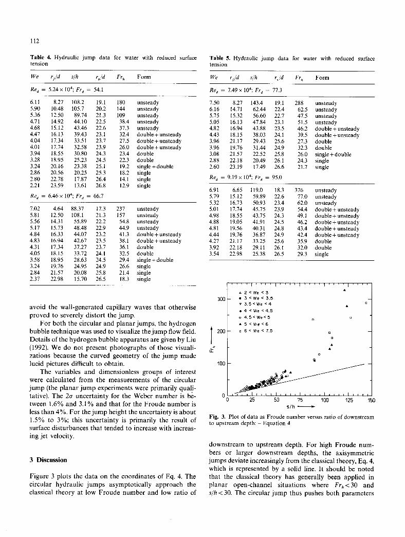
Figure 3 plots the data on the coordinates of Eq. 4. The circular hydraulic jumps asymptotically approach the classical theory at low Froude number and low ratio of
Table 5. Hydraulic jump data for water with reduced surface tension
We rj /d s/h rs/d Fr h Form
Re d = 7.49 x 10⁴; Fr d = 77.3
7.50 8.27 143.4 19.1 288 unsteady 6.16 14.71 62.44 22.4 62.5 unsteady 5.75 1 5 . 3 2 56.60 22.7 47.5 unsteady 5.05 16.13 47.84 23.1 51.5 unsteady 4.82 1 6 . 9 4 43.88 23.5 46.2 double+unsteady 4.43 18.15 38.03 24.1 39.5 double + unsteady 3.96 21.17 29.43 25.6 27.3 double 3.96 1 9 . 7 6 31.44 24.9 32.3 double 3.08 21.57 22.52 25.8 26.0 single + double 2.88 22.18 20.49 26.1 24.3 single 2.60 23.19 17.49 26.6 21.7 single
Re a = 9.19 x 10⁴; Fr d = 95.0
6.91 6.65 119.0 18.3 376 unsteady 5.79 1 5 . 1 2 59.89 22.6 77.0 unsteady 5.32 16.73 50.93 23.4 62.0 unsteady 5.01 17.74 45.75 23.9 54.4 double + unsteady 4.98 18.55 43.75 24.3 49.1 double + unsteady 4.88 19.05 41.91 24.5 46.2 double + unsteady 4.81 19.56 40.31 24.8 43.4 double+unsteady 4.44 1 9 . 7 6 36.87 24.9 42.4 double+unsteady 4.27 21.17 33.25 25.6 35.9 double 3.92 22.18 29.11 26.1 32.0 double 3.54 22.98 25.38 26.5 29.3 single
s
300
200
100
. . . . I ' ' ' ' I ' ' ' ' I ' ' ' ' I ' ' ' ' I ' ' ' '
=, 2 < W e < 3 �9 5 < W e < 3 . 5
v 3 . 5 < W e < 4
o 4 < W e < 4 . 5
o 4 . 5 < W e < 5
�9 5 < W e < 6
= 6 < W e < 7 .5
O O
O
O
O
O
0 0 25 50 75 100 125 150
s / h -
Fig. 3. Plot of data as Froude number versus ratio of downstream to upstream depth: - Equation 4
downstream to upstream depth. For high Froude num- bers or larger downstream depths, the axisymmetric jumps deviate increasingly from the classical theory, Eq. 4, which is represented by a solid line. It should be noted that the classical theory has generally been applied in planar open-channel situations where Frh<30 and s/h < 30. The circular jump thus pushes both parameters

well 15eyond the established range of the theory. The trends of Fig. 3 are consistent with the failures of Watson's theory reported by other investigators for large down- stream depths and small jump radii (the latter correspond- ing to higher supercritical Froude number).
Let us examine these departures in the context of the shape of the hydraulic jump and in relation to surface tension forces.
3.1 Observations of the jump's form
Several forms of circular jump appeared sequentially in the experiments as the downstream depth was increased (Fig. 4). For small differences between supercritical and subcritical depths, a smooth jump occurs in which the depth increases gradually and without any flow reversal. As the downstream depth increases, the hydrostatic pres- sure along the sloped jump surface becomes larger; this finally results in a backward flowing roller on the free surface, giving a cusped jump interface. This single-roller jump is the case shown in Fig. 1. The single-roller jump has a very abrupt transition in liquid depth, and this sharp change in hydrostatic pressure creates a separated eddy on the wall just behind the free surface roller; the main flow travels at high speed between the two vortices. Both the surface roller and the wall vortex were confirmed by our hydrogen bubble experiments (although the surface roller can be seen with the naked eye). The flow immedi- ately after the jump was not unidirectional and showed very complex patterns.
With a further increase in downstream depth, the single roller on the jump surface becomes lower than the downstream flow, giving the surface the appearance of a double jump (Fig. 5). This double structure is less smooth and steady than the single roller, and shows unsteady azimuthal variations on the free surface. The distance between the two "jumps" varies with jet velocity, diminishing at lower velocity. If the downstream depth is decreased, the double jump reverts to a single jump.
If instead the downstream depth is increased further, the double jump becomes unstable, and entrains increas- ing amounts of air. Finally, all semblance of order is lost (Fig. 6), and the jump becomes entirely unstable. The liquid surface is turbulent, traps air bubbles, and tesselates radially with no appearance of axisymmetry. This condi- tion is similar to the usual picture of an open-channel hydraulic jump.
The edge of the single and double jumps is basically circular for stable laminar incoming jets. On this circle, a pronounced azimuthal wave pattern can sometimes be seen. For very stable incoming jets and small jet velocities the wave pattern is very regular and periodic. This azimuthal instability is different from the sequence of vertical instabilities just described, and it appears to be a type of Taylor instability produced by the density differ-
113
\ \ \ \ \ \ ~ \ \ ' \ \ \ \ \ ' \ ' \ \ \ \
a
\ \ \ \ , ~ ,, \ \ x \ \ x x ~ \ \ \ \
b
\ \ ,~ ' \ x \ \ \ \ \ \ \ \ \ \ \ \ \ k
e
\ ' \ \ x \ \ \ ' ~ \ \ \ x \ \ \ \ \ x \
d
Fig. 4a-d. Instabilities of the circular jump: a jump without roller; b jump with single roller; c jump with double roller; d unstable jump with turbulent flow and air entrainment
Fig. 5. Jump with double roller: Re a = 51,500, d=4.96mm, r~ = 90.3 mm, s = 9.2 mm
ence between the air and the water. The wave pattern disappears as the flow rate increases. This azimuthal insta- bility is similar to that reported by Craik et al. (1981).
3.2 The role of surface tension
Open channel hydraulics has long been focused on large scale jumps as found in dam spillways. In that literature (e.g., Peterka, 1963) the supercritical liquid sheet is typi- cally several centimeters thick and the subcritical sheet is thicker still. Surface tension forces are entirely negligible

114
Fig. 6. Unstable jump: Re d =45,500, d=4.96 mm, s= 13.2 mm
~- ' ' ' I . . . . I ' ' ' ' I . . . . I . . . . I . . . .
~ t L ~ ~ / / c~ 12<Frh<22_ t-~ [ ~ ~ ~,~'o o / o . / o 22 < Fr h < 2 8 %a ~ x / v /
L ~ o q~ / v v 0 / v 2 8 < F r h < 3 5 ,
I ..~.~ ~ ~'-~?" o oo / o 35< ~,, <43 ,~nl r a / a / o V O / o 4 5 < Fr h < 5 5 - LUF-- ~ , o o o v o / o o / - ~
l '~ / ,4" v v / �9 o / �9 ~: : ' - Frh < I00 . I - ? 9 " - ~ q~ '~ ~ 1 7 6 " Y I IO0 < Frh - ] / -~ ~ I .q ~ / oOooc~/o �9 t 1 6 F . ~ . ~ ...~ ./~, '~ 4 - ~
1 2 [ - ~ ; ~ " ,-o /- ..
I <>~ ,~* .... 8~ ,, �9 "
Ot-/~,,, , I , , L, I , , , , t . . . . I , , , , I 3 & 5 6 7 8
We -~
Fig. 7. Circular jump data (dimensionless jump radius versus Weber number) showing regions of jump forms
for such thicknesses, and they cannot suppress the surface turbulence observed. For the circular jumps shown here, the thickness of the subcritical liquid sheet is only millimeters and the surface tensiorI is dynamically impor- tant. Balancing the hydrostatic pressure force behind the jump and the surface tension force along the surface of the jump gives
pgs ~ a/R (5)
where R is the radius of curvature of the surface roller. Our observations show that the radius of curvature at the jump is about one half of the jump height, s. Hence, surface tension can balance the hydrostatic pressure be- hind the jump if
s ~ / 2 a (6) ~/ Pg
For water, the thickness s is on the order of millimeters when the pressure and surface tension forces are in bal- ance. Surface tension stabilizes the surface of the axisym- metric jump primarily because the subcritical film is thin.
One principal result of the stabilization of the free surface is an increase in the adverse pressure gradient along the wall, because the change in liquid height can occur more abruptly than for the more spread-out, unstable surface. As noted earlier, the adverse gradient produces a separation vortex beneath the jump. The sep- arated region along the wall may therefore be regarded as a consequence of surface tension stabilization, rather than a consequence of axisymmetry.
We may examine the role of surface tension in stabil- izing the jump by introducing a jump Weber number that characterizes the ratio of the hydrostatic force to the restraining surface tension force:
We=s ~ (7) ~ a
In Fig. 7 the form of the jump is shown as a function of Weber number and dimensionless jump radius for various values of the Froude number and of the surface tension. If the shape of the jump were solely determined by the Weber number, then the different regions of jump form would be divided by the lines normal to the horizontal axis. The figure shows that this is not the case. The borders of different types of jump are at some angle to the Weber number axis and thus depend on both Weber number and the jump radius. This implies that the type of jump is not only a function of the Weber number, but also of the factors defining r/d. Nevertheless, the controlling influence of the Weber number is apparent. In particular, the single roller jump occurs only in the range of smallest Weber number.
If the preceding arguments are correct, it follows that similar phenomena should occur in a planar jump if the liquid sheet has a thickness that is of the order of millimeters. Such a flow should differ from the classical planar jump through the strong influence of surface ten- sion on the jump surface. Fig. 8 is a photo of such a thin planar jump. The liquid issued from a gate with a gap of about 1.9 mm from the bottom wall. The free surface is smooth and a cusp can be seen at the jump. For the planar jump there is not only a surface roller, but also a hump upstream of it. Hydrogen bubble visualization showed that this hump was in fact a recirculating vortex beneath the film, over which the supercritical flow travelled (Fig. 9). As in the circular jump, this vortex probably results from boundary layer separation caused by the adverse hydrostatic pressure gradient. In contrast to the circular jump, the separation vortex has moved from the subcriti- cal region into the supercritical region. The backflowing surface roller now sits somewhat behind it. However, these

115
Fig. 9. Flow field for the hydraulic jump in a thin planar flow
Fig. 8. Planar hydraulic jump in a thin water film issuing from a 1.9 mm high gate. Fr h ~ 26.2, s/h~8.6, We~3.63
observations confirm the peculiar behavior to result from the thinness of the liquid sheet and the effects of surface tension, rather than from an axisymmetric geometry.
3.3 The departure from the standard theory
To quantify the extent of the departure from the standard control volume momentum balance, we may introduce a fictitious drag force that corrects for the velocity nonuniformity of the separation, as well as for any wall drag beneath the separated region. We locate the up- stream end of the control volume just before the jump and the downstream end at some point in the subcritical region. In this case, the momentum balance (Fig. 2) becomes
(;o ;o ) = -- D + 27zr, pu(r~, y)2dy + p dy (8)
where D is a drag force exerted on the liquid control volume in the downstream direction. Using the depth average velocity to evaluate the integrals and introducing the upstream (supercritical) Froude number as before
Fr h -- uyd~2 (9) 8r j Jgh 3
as well as the downstream (subcritical) Froude number
ufd2 (10) Fr~- 8 r ~ x / ~
we can rearrange the above equation to obtain:
1 2 (11) ( F r s ~ ' / 3 ( l _ t _ F r 2 ) = ( ~ q _ F r s ) D
1.0
0.8 E c-
G)
o E 0.6 E
--. 0./.
0.2
I l l L [ J l , l [ n l l q l ~ ] ] u ] n ] l l l l ~ l n I ,
o �9 �9 v o v
~Q
�9 ~ vnl
�9 z~ 0 o 0
�9 ~ �9 ~ A ~ O~ 'gl~O �9 V Re d �9 �9 �9 v � 9 Oo0 8 � 9 0 ~ � 9 ~ 5 , 2 4 x 1 0 4 0,074
z~ao 0 �9 o ~ v o �9 �9 u 6 . 4 6 x l O 4 0 .074 v v � 9 �9 VT. 4 9 x l O 4 0 . 0 7 4
o ~ �9 0 8 . 3 9 x 1 0 4 0 .074 �9 v ~ o �9 �9 �9 0 9 . 5 9 x 1 0 4 0 ,074
a ~, '~ : ~ ~, ~ & l l .O x lO 4 0 .074 o ,~ �9 �9 �9 5 . 2 4 x 10⁴ 0 .057
oo ~ �9 6 . 4 6 x lO 4 0 ,057
�9 �9 7 . 4 9 x 1 0 4 0 .057
�9 o 9 . 2 0 x 1 0 4 0 .057
2 3 ~ 5 6 7 8 We
Fig. 10. Plot of dimensionless total momentum loss as a function of Weber number for various Reynolds numbers.
The drag term itself is likely to depend on the Reynolds number, the Weber number, and a term characterizing jump length, such as (rs-rj)/d.
Figure 10 shows the dimensionless momentum deficit,
which is - ~ divided by the terms on the lefthand side of pgs ~
equation. Here, the highest depth in the subcritical region was taken as the downstream depth, s, and the velocity was assumed positive in the radial direction. The figure shows that the fictitious momentum loss can be a very large portion of the total momentum. The loss increases with jet Reynolds number. The loss curves for constant Reynolds number each seem to have a minimum at a Weber number between 3 and 4, a region typically corresponding to the double jump. The loss grows steadily as the Weber number rises beyond this, in the region of unstable jumps. As the Weber number decreases below 3, the single jump region, the loss also grows. While this may imply a greater viscous loss for the single jump structure, it must also be realized that these jumps occur nearer to the lip of the target plate (which is at a radius of 30.5d; cf. Tables 1-5), a situation that may influence the subcritical flow.
Finally, we note that a full prediction of the circular jump radius will in fact depend on six dimensionless

116
groups (for details of the dimensional analysis, see Liu, 1992). If the initial condit ions are set at the jet nozzle, an appropr ia te functional equat ion is
( ~=F _Red, Frd, Wea, d' d f (12)
Here, the dimensionless j u m p radius, r/d, is a function of: the jet Reynolds and Froude numbers, Red=uyd/v and
Frd = U y / ~ , which together describe the radial evolu- tion of the local supercritical Froude number; the jump Weber number, which controls the jump shape; and the dimensionless downst ream depth, s/d, and the dimension- less radius, r~/d at which that depth occurs. Previous studies have accounted for only some of these parameters, which may explain some of the difficulties they reported.
4 Conclusions
Hydraul ic jumps in thin liquid sheets are stabilized by surface tension, resulting in very smooth jumps for low values of an appropr ia te Weber number. As this Weber number increases, the j u m p surface undergoes a series of instabilities, finally reaching a turbulent condit ion similar to that seen in classical open-channel hydraulic jumps. The surface tension stabilization promotes separation of the flow along the wall in the vicinity of the jump, leading to a wall vortex in the subcritical region. In addition, a smooth backflow can occur on the front surface of a stable hydraulic jump. While these effects are most easily seen in circular hydraulic jumps, similar phenomena occur in planar flows when they are sufficiently thin.
Circular hydraulic jumps can show large disagree- ments with simple (uniform subcritical flow) models for jump. These disagreements are worse when the ratio of downst ream to upstream depth is large or when the super- critical Froude number at the jump radius is large. A full
theory of the circular hydraulic j ump must include both parameters describing upstream and downstream flow evolution a n d parameters describing the stability of the jump surface.
Acknowledgements The authors are grateful to Mr. Vittal K. Vasista for his help in building the circular jet apparatus and in running initial experiments with it. This work was supported by the US National Science Foundation under grant no. CBT-8858288.
References
Bouhadef, P. M. 1978: l~talement en couche mince d'un jet liquide cylindrique vertical sur un plan horizontal. Journal de Mathematiques et de Physique appliqu6es (ZAMP) 29
Craik, A. D. D.; Latham, R. C.; Fawkes, M. J.; Gribbon, P. W. F. 1981: The Circular Hydraulic Jump. J. Fluid Mech. 112, 347-362
Errico, M. 1986: A Study of the Interaction of Liquid Jets with Solid Surfaces. PhD Diss., University of California at San Diego
Ishigai, S.; Nakanishi, S.; Mizuno, M.; Imamura, T. 1977: Heat Transfer of the Impinging Round Water Jet in the Interference Zone of Film Flow along the Wall. Bull. JSME 20 (139), 85-92
Liu, X. 1992: Liquid Jet Impingement Heat Transfer and its Poten- tial Applications at Extremely High Heat Fluxes. PhD Diss., Massachusetts Institute of Technology
Nakoryakov, V. E.; Pokusaev, B. G.; Troyan, E. N. 1978: Impinge- ment of an Axisymmetric Liquid Jet on a Barrier. Int. J. Heat Mass Transfer 21, 1175-1184
Olsson, R. G.; Turkdogan, E. T. 1966: Radial spread of a liquid stream on a horizontal plate. Nature 211 (5051), 813-816
Peterka, A. J. 1963: Hydraulic Design of Stilling Basins and Energy Dissipators. U. S. Dept. Interior, Bur. Reclamation, Engr. Mono- graph 25
Thomas, S.; Faghri, A.; Hankey, W. 1991: Experimental Analysis and Flow Visualization of a Thin Liquid Film on a Stationary and Rotating Disk. J. Fluids Engineering 113, 73-80
Vasista, V. K. 1989: Experimental Study of the Hydrodynamics of an Impinging Liquid Jet. S. B. Thesis, Massachusetts Institute of Technology
Watson, E. J. 1964: The radial spread of a liquid over a horizontal plane. J. Fluid Mech. 20, 481 499