Conjugate Jet Impingement Heat Transfer Investigation via ...

Entropy generation due to jetimpingement on a surface: effectof annular nozzle outer angle
S.Z. Shuja, B.S. Yilbas and M.O. BudairME Department, KFUPM, Dhahran, Saudi Arabia
Abstract
Purpose – The purpose of this paper is to examine entropy generation rate in the flow field due jetemanating from an annular nozzle and impinging on to a flat plate. Since the flow field changes withthe geometric configuration of the annular nozzle, the influence of nozzle outer cone angle on theentropy generation rate is considered.
Design/methodology/approach – The steady flow field pertinent to jet impingement on to a flatplate is modeled with appropriate boundary conditions. A control volume approach is introduced todiscretize the governing equations of flow and to simulate the physical situation numerically. Entropygeneration rate due to heat transfer and fluid friction is formulated. The resulting entropy equationsare solved numerically.
Findings – Thermodynamic irreversibility, which is quantified through entropy generation rate,gives insight into the thermodynamics losses in the flow system. Entropy generation rate is highlyaffected by the nozzle outer cone angle. In this case, increasing nozzle outer cone angle enhances theentropy generation rate, particularly due to fluid friction.
Research limitations/implications – The predictions may be extended to include the nozzle arearatio and mass flow rate variation.
Practical implications – The paper is a very useful source of physical information for improvingnozzle design, particularly that which is used in a laser thick material cutting operation. Itdisseminates information for those working on both laser machining applications and entropygeneration in flow systems.
Originality/value – This paper discusses the physical issues related to the entropy generation rateand offers practical help to an individual starting out on an academic career.
Keywords Thermodynamic properties, Fluid phenomena, Jets, Substrates
Paper type Research paper
NomenclatureD ¼ nozzle exit diameter (m)H ¼ enthalpyK ¼ thermal conductivityk ¼ turbulent kinetic energyKeff ¼ effective thermal conductivity (W/mK)Kl ¼ bulk thermal conductivity (W/mK)Kt ¼ turbulent thermal conductivity
(W/mK)
p ¼ pressureP ¼ rate of productionRij ¼ Reynolds stressRe ¼ Reynolds No.r ¼ distance in the radial direction_S 000
gen ¼ volumetric entropy generation rate(W/m3K)
t ¼ time
The current issue and full text archive of this journal is available at
www.emeraldinsight.com/0961-5539.htm
The authors acknowledge the support of King Fahd University of Petroleum and Minerals,Dhahran, Saudi Arabia, for this work.
Entropygeneration due tojet impingement
677
Received 12 June 2006Revised 10 October 2006
Accepted 16 November 2006
International Journal of NumericalMethods for Heat & Fluid Flow
Vol. 17 No. 7, 2007pp. 677-691
q Emerald Group Publishing Limited0961-5539
DOI 10.1108/09615530710777958

T ¼ temperatureu * ¼ friction velocityU ¼ arbitrary velocityV ¼ axial velocity componentW ¼ radial velocity component; ¼ volumez ¼ distance in the axial direction
Greeka ¼ thermal diffusivityG ¼ arbitrary diffusion coefficient1 ¼ energy dissipationl ¼ turbulence intensitymeff ¼ effective viscosity (Ns/m2)mt ¼ turbulent viscosity (Ns/m)ml ¼ laminar viscosity (Ns/m2)n ¼ kinematic viscosityr ¼ density (function of temperature and
pressure for gas)s ¼ variable Prandtl No.u ¼ nozzle cone angle
F ¼ viscous dissipationf ¼ arbitrary variableP ¼ energy transport due to pressure
excluding strain interactionsPw ¼ energy transport due to wall
reflectionL ¼ energy transport by diffusion
Subscriptamb ¼ ambienti, j ¼ arbitrary directionjet ¼ gas jet at inletl ¼ laminarmax ¼ maximump ¼ a typical node in the computational
gridt ¼ turbulentv ¼ viscous sub-layerw ¼ wallv ¼ viscous sublayer
1. IntroductionAnnular nozzles can be used to improve laser deep penetrated processing of metallicsubstrates. In this case, gas emerging from the nozzle impinges onto the surface ofthe workpiece. Flow structure around the surface of the workpiece influencessignificantly heat transfer rates from the surface. Moreover, flow structure in thisregion is influenced by the nozzle geometric configurations. Thermodynamicirreversibility associated with flow field gives insight into the flow structureof the impinging jet. Entropy generation in the flow system provides information inthermodynamic irreversibility. Consequently, investigation into entropy generationduring jet emerging from annular nozzle and impinging onto a flat plate surfacebecomes essential.
Considerable research studies were carried out to examine jet impingement ontosurfaces. The effect of nozzle diameter on heat transfer characteristics from theimpinging surface was studied by Lee et al. (1995). They showed that local Nusseltnumber increased with increasing jet diameter in the stagnation region, which wasattributed to an increase in the jet momentum and turbulence intensity level with thelarge nozzle diameter. Effect of nozzle geometry on flow characteristics and heattransfer from impinging surfaces was examined by Dano (2005). They indicatedthat the flow development from the cusped ellipse nozzle affected the wall region flowmore than the circular nozzle; in addition, the overall heat transfer for the uniform heatflux boundary condition was found to increase when the cusped ellipse nozzle wasused. The effects of nozzle configuration on cooling rates from concave surfaces wereinvestigated by Yang et al. (1999). They showed that average heat transfer rates forimpingement on the concave surface was more than the flat plate. Heat transfer ratesfrom impinging surface due to annular jet were studied by Hiroshi and Akira (1989).They showed that the flow pattern of the annular impinging jet was divided in threeregions and that the Nusselt number in the stagnation region had a weak dependency
HFF17,7
678

on the Reynolds number. The effect of nozzle geometry on local convective heattransfer due to a confined impinging air jet was investigated by Colucci and Viskanta(1996). They indicated that the local heat transfer coefficients for confined jet weremore sensitive to Reynolds numbers and nozzle-to-plate spacing than those forunconfined jets. Jet impingement and heat transfer due to low nozzle-plate spacing wasexamined by Lytle and Webb (1994). They showed that the outer peak in local Nusseltnumber was found to move radially outward for large nozzle-to-plate spacings andhigher jet Reynolds numbers. Heat transfer due to an impinging jet on a flat plate wasstudied by Huang and El-Genk (1994). They showed that maximum Nusselt numberwas strong function of nozzle-to-plate spacing and nozzle diameter. Heat transfer fromimpinging surface due to a round jet was examined by Mohanty and Tawfek (1993).They introduced functional relation between the nozzle effective area and heat transferrates from the surface. The influence of nozzle geometric configurations on flowstructure and heat transfer rates in the stagnation region were examined by Shuja et al.(2005). They showed that nozzle configuration had significant effect on the heattransfer rates from the flat surface and complex flow structure was formed in thestagnation region. However, thermodynamic analysis for irreversibility in the flowsystem was left obscure.
Thermodynamic irreversibility analysis provides process optimization andimproved design configurations of thermal systems (Bejan, 1982). The rate ofentropy generation can be used to quantify thermodynamic irreversibility in the flowsystem. Considerable research studies were carried out to examine entropy generationin flow systems. Entropy generation and minimization in thermal systems forimproved operation and design was examined by Bejan (1982). He showed that entropygeneration rate could be used as an effective tool for optimum design of thermalsystems. The second law analysis in convective heat transfer problems wasinvestigated by Mahmud and Eraser (2003). They developed an analytical expressionfor Bejan number due to different flow situations. Entropy generation in developingand fully developed flows was studied by Carrington and Sun (1992). They formulatedentropy production rate in terms of flow properties. Second law analysis in swirlingflow was carried out by Mukherjee et al. (1987). They determined local Nusselt numberand rate of entropy production. Entropy generation in pipe flow due to restrictions wasexamined by Yilbas et al. (1999). They developed relation between entropy productionrate, Swirl and Merit numbers.
In the present study, entropy generation in the flow system due to jet emerging froman annular nozzle and impinging onto a flat plate is considered. Effect of nozzlegeometric con-figurations on entropy generation rate is examined. A numerical schemeemploying a control volume approach is introduced in the simulations and air is usedas impinging gas.
2. Flow analysisIn laser gas assisted processing, the impinging jet conditions are mainly steady;consequently, a steady flow conditions are considered in the analysis, provided that thecompressibility effect and variable properties are accommodated. The jet impingingonto a uniformly heated flat plate is simulated. The heat source with a constant heatflux is considered at the plate surface. The geometric arrangements of the annular
Entropygeneration due tojet impingement
679

Figure 1.Cross-sectional view ofconical nozzle:(a) boundary conditions;and (b) grid used in thesimulations. The coneangle of the nozzle is 258
r/D
x/D
012345
0
4
8
12
16
(a)
Inlet Boundary
Sym
met
ry A
xis
SOLID
Heated PlateA
Wal
l
r/D
x/D
012345
0
4
8
12
16
(b)
Nozzle No. Cone angle (u8)
1 252 353 454 55
Table I.Geometry configurationof annular conical nozzle
HFF17,7
680
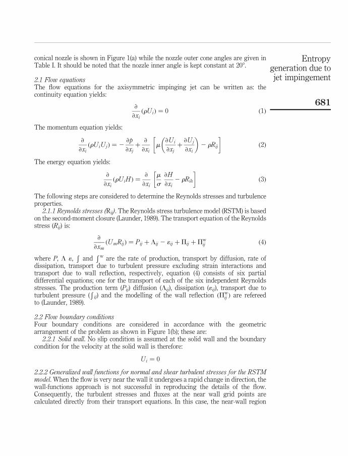
conical nozzle is shown in Figure 1(a) while the nozzle outer cone angles are given inTable I. It should be noted that the nozzle inner angle is kept constant at 208.
2.1 Flow equationsThe flow equations for the axisymmetric impinging jet can be written as: thecontinuity equation yields:
›
›xiðrUiÞ ¼ 0 ð1Þ
The momentum equation yields:
›
›xiðrUiUjÞ ¼ 2
›p
›xjþ
›
›xim
›Ui
›xjþ
›Uj
›xi
� �2 rRij
� �ð2Þ
The energy equation yields:
›
›xiðrUiH Þ ¼
›
›xi
m
s
›H
›xi2 rRih
� �ð3Þ
The following steps are considered to determine the Reynolds stresses and turbulenceproperties.
2.1.1 Reynolds stresses (Rij). The Reynolds stress turbulence model (RSTM) is basedon the second-moment closure (Launder, 1989). The transport equation of the Reynoldsstress (Rij) is:
›
›xmðUmRijÞ ¼ Pij þ Lij 2 1ij þPij þPw
ij ð4Þ
where P, L 1,R
andRw are the rate of production, transport by diffusion, rate of
dissipation, transport due to turbulent pressure excluding strain interactions andtransport due to wall reflection, respectively, equation (4) consists of six partialdifferential equations; one for the transport of each of the six independent Reynoldsstresses. The production term (Pij) diffusion (Lij), dissipation (1ij), transport due toturbulent pressure (
Rij) and the modelling of the wall reflection ðPw
ij Þ are refereedto (Launder, 1989).
2.2 Flow boundary conditionsFour boundary conditions are considered in accordance with the geometricarrangement of the problem as shown in Figure 1(b); these are:
2.2.1 Solid wall. No slip condition is assumed at the solid wall and the boundarycondition for the velocity at the solid wall is therefore:
Ui ¼ 0
2.2.2 Generalized wall functions for normal and shear turbulent stresses for the RSTMmodel. When the flow is very near the wall it undergoes a rapid change in direction, thewall-functions approach is not successful in reproducing the details of the flow.Consequently, the turbulent stresses and fluxes at the near wall grid points arecalculated directly from their transport equations. In this case, the near-wall region
Entropygeneration due tojet impingement
681

lying between the wall and the near-wall computational node at xp can be represented
by two layers: the fully viscous sublayer, defined by Rev ¼ xv
ffiffiffiffiffikv
p=v ø 20; and a fully
turbulent layer. The wall shear stress near the wall is employed, i.e. vwjzv¼ tw=r;
which serves as the boundary condition for the vw transport equation.In relation to normal stresses, the turbulence energy must decrease quadratically
towards a value of zero at the wall (Benocci, 1991) therefore a zero-gradient conditionfor the normal stresses is physically realistic. This situation is insufficient to ensure anaccurate numerical representation of near-wall effects. An improved approach forinternal cells is needed in respect of evaluating volume-integrated production anddissipation of normal stresses (these are normally evaluated at cell centres, using linearinterpolation, and then multiplied by the cell volume). Considering v2 as an example,the volume-integrated production of v2 between the wall and the P-node may beapproximated by Hogg and Leschziner (1989), i.e:Z
Dr
Z zp
0
P22 d; øZDr
Z xp
xv
2 2vw›V
›xd; ¼ 2tw
V p 2 V v
xp 2 xv
� �xpDr ð5Þ
where Vp and Vv follow from the log-law. No contribution arises from the viscoussublayer since vw ¼ 0 in this layer. An analogous integration of the dissipation ratewith the assumptions:
1 ¼2vkv
x2v
0 # x # xv
1 ¼C3=4m k
3=2p
kxvxv # x , xp
leads to:
ZDr
Z xp
0
1 d; ø2vkp
xvþ
C3=4m k
3=2p
kln
xp
xv
� �" #er ð6Þ
an analogous treatment is applied to___
v 2, while the production of___
w 2 in the viscous andturbulent near wall layers region is zero (Versteeg and Malalasekera, 1995).
The values resulting from equations (5) to (6) are added, respectively, to thevolume-integrated generation and dissipation computed for the upper half of thenear-wall volume.
It should be noted that for the wall-law approach, the near-wall dissipation (1p) is notdetermined from its differential equation applied to the near-wall cell surrounding thenode. Instead, and in accordance with the log law, this value is obtained via the lengthscale from 1p ¼ C3=4
m k3=2p =kzp; which serves as the boundary conditions for inner cells.
2.2.3 Inlet conditions. The boundary conditions for temperature and mass flow rateneed to be introduced at nozzle inlet:
T ¼ specified ð300 KÞ and _m ¼ specified ð0:0084 kg=sÞ
The mass flow rate of the annular conical nozzles corresponding to the differentconfigurations is kept the same.
HFF17,7
682

Similarly, the mass flow rate of the pipe is kept the same as the annular nozzles.It should be noted that the pipe length is extended to secure the fully developedturbulent flow in the pipe before emerging from the pipe exit and impinging on to thecavity.
The values of k and 1 are not known at the inlet, but can be determined fromturbulent kinetic energy, i.e.:
k ¼ l�u 2 ð7Þ
where �u is the average inlet velocity and l is a percentage.The dissipation is calculated from: 1 ¼ Cmk
3=2=aD; where D is the diameter. Thevalues l ¼ 0.03 and a ¼ 0.005 are commonly used and may vary slightly in theliterature (Elkaim et al., 1992).
2.2.4 Outlet. The flow is considered to be extended over a long domain; therefore,the boundary condition (outflow boundaries – Figure 1(b)) for any variable f is:
›f
›xi¼ 0 ð8Þ
where xi is the normal direction at outlet.2.2.5 Symmetry axis. At the symmetry axis, the radial derivative of the variables is
set to zero, i.e.:
›f
›r¼ 0 ð9Þ
except:
V ¼ vw ¼ vh ¼ wh ¼ 0
2.2.6 Solid wall (flat plate surface): uniform heat flux boundary. A uniform heatflux boundary is considered at the flat plate surface. The magnitude of the heat fluxis set 1 W/m2.
2.3 Gas propertiesThe equation of state is used for air and the properties employed are given in Table II.
3. Entropy analysisThe non-equilibrium phenomenon in a flow system causes a continuous generation ofentropy in the flow field. The heat flux is driven by the temperature gradient and theflux of momentum is driven by the velocity gradient. The point-size control volumeformulation of the second law gives (Bejan, 1995):
Property Air
Density r (kg/m3) p/RTThermal conductivity K (W/mK) 0.0242Specific heat capacity cp (J/kgK) 1006.43Viscosity v (kg/m s) 1.7894 £ 10-5
Table II.Air properties used
in the simulation
Entropygeneration due tojet impingement
683
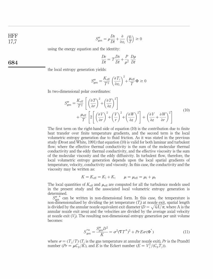
S000gen ¼ r
Ds
Dtþ
›
›xi
qiT
� �$ 0
using the energy equation and the identity:
De
Dt¼ T
Ds
Dtþ
P
r 2
Dr
Dt
the local entropy generation yields:
S000gen ¼
Keff
T 2
›Ti
›xi
� �2
þmeff
TF $ 0
In two-dimensional polar coordinates:
S000gen ¼
Keff
T 2
›T
›r
� �2
þ›T
›z
� �2" #
þmeff
T2
›V
›r
� �2
þV
r
� �2
þ›W
›z
� �2" #
þ›V
›zþ
›W
›r
� �2" # ð10Þ
The first term on the right-hand side of equation (10) is the contribution due to finiteheat transfer over finite temperature gradients, and the second term is the localvolumetric entropy generation due to fluid friction. As it was stated in the previousstudy (Drost and White, 1991) that equation (10) is valid for both laminar and turbulentflow; where the effective thermal conductivity is the sum of the molecular thermalconductivity and the eddy thermal conductivity, and the effective viscosity is the sumof the molecular viscosity and the eddy diffusivity. In turbulent flow, therefore, thelocal volumetric entropy generation depends upon the local spatial gradients oftemperature, velocity, conductivity and viscosity. In this case, the conductivity and theviscosity may be written as:
K ¼ Keff ¼ K l þ K t m ¼ meff ¼ ml þ mt
The local quantities of Keff and meff are computed for all the turbulence models usedin the present study and the associated local volumetric entropy generation isdetermined.
S000gen* can be written in non-dimensional form. In this case, the temperature is
non-dimensionalized by dividing the jet temperature (Tj) at nozzle exit, spatial lengthis divided by the annular nozzle equivalent exit diameter (D ¼
ffiffiffiffiffiffiffiffiffiffiffiffi4A=p
p, where A is the
annular nozzle exit area) and the velocities are divided by the average axial velocityat nozzle exit (Vj). The resulting non-dimensional entropy generation per unit volumebecomes:
S000*gen ¼
S000genD
2
K¼ s 2ð7T*Þ2 þ Pr Es ðF
*Þ ð11Þ
where s ¼ ðTj=TÞ (Tj is the gas temperature at annular nozzle exit), Pr is the Prandtlnumber ðPr ¼ mCp=KÞ, and E is the Eckert number ðE ¼ V 2
i =ðCpTjÞÞ.
HFF17,7
684

The volumetric averaged dimensionless entropy generation can be written as:
_S*gen ¼
Z;
S000genD
2
Kdu dzr dr ð12Þ
4. Numerical method and simulationA control volume approach is employed when discretizing the governing equations.The discretization procedure is given in Patankar (1980) The problem of determining thepressure and satisfying continuity may be overcome by adjusting the pressure field soas to satisfy continuity. A staggered grid arrangement is used in which the velocities arestored at a location midway between the grid points, i.e. on the control volume faces. Allother variables including pressure are calculated at the grid points. This arrangementgives a convenient way of handling the pressure linkages through the continuityequation and is known as semi-implicit method for pressure-linked equations (SIMPLE)algorithm. The details of this algorithm is given in Patankar (1980).
The computer program used for the present simulation can handle a non-uniformgrid spacing. In each direction, fine grid spacing near the gas jet impinging point andthe cavity is allocated while gradually increased spacing for locations away from thecavity is considered. The number of grid planes used normal to the x and r directionsare 220 and 272, respectively, for the pipe and the conical annular nozzle (Figure 1(b)).The grid independence tests were conducted and it is observed that the grid selectedresults in the grid independent solution.
Nine variables are computed at all grid points; these are: two velocity components,local pressure, five turbulence quantities and the temperature.
5. Results and discussionsEntropy generation due to flow emerging from an annular conical nozzle andimpinging onto a flat plate is considered. The influence of annular nozzle outer angleon the entropy generation rate is examined. Since, the flow field is turbulent, RSTM isemployed to account for the turbulence.
Figure 2 shows contours of non-dimensional volumetric entropy generation rate dueto fluid friction for four outer angles of annular nozzles. Entropy generation rate is highin the region of nozzle existing and in the vicinity of the plate surface. Since, the nozzleexit velocity profile is non-symmetric due to annular flow, in which case, the rate offluid strain changes across the nozzle exit vicinity. This in turn results in significantviscous dissipation in this region. Entropy generation rate increases in the region ofstagnation due kinetic energy loss. Once the pressure builds up in this region, radialflow is generated along the plate vicinity towards the outlet boundary. This situationresults in viscous dissipation in this region, which is more pronounced in the regionwhere flow acceleration is high, i.e. next to stagnation region. Streamline curvature ofthe impinging jet enhances the frictional losses in the radial direction, since radialmomentum dominates the axial momentum in this region. In this case, rate of fluidstrain in the region next to the plate surface increases due to increased radialmomentum of the jet. The influence of the nozzle outer angle on entropy generation ratebecomes high in the region of nozzle exit and stagnation region. Increasing nozzle outerangle modifies the radial distribution of the jet velocity at nozzle exit. In this case,
Entropygeneration due tojet impingement
685
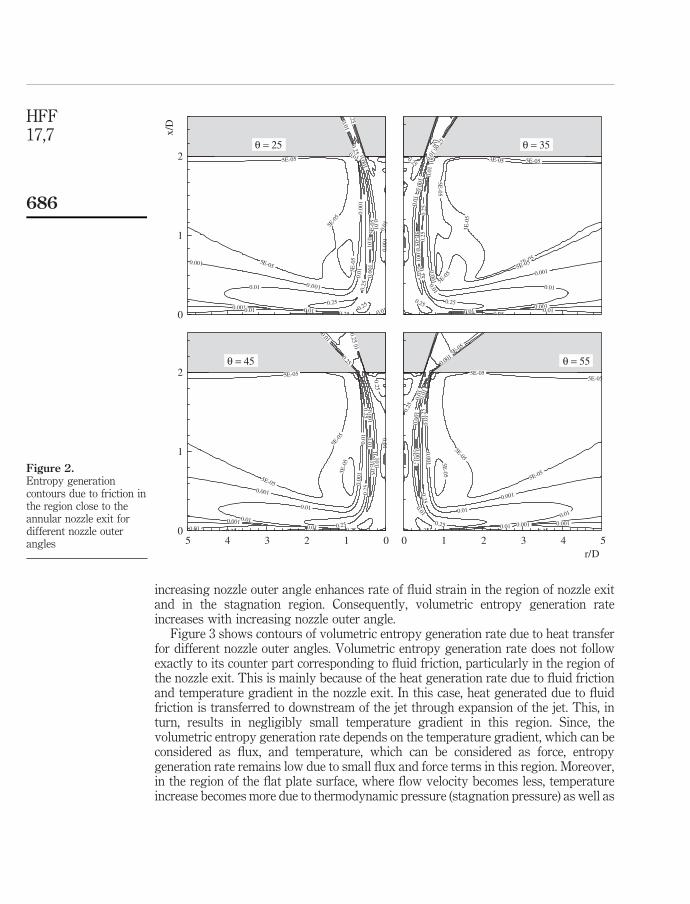
increasing nozzle outer angle enhances rate of fluid strain in the region of nozzle exitand in the stagnation region. Consequently, volumetric entropy generation rateincreases with increasing nozzle outer angle.
Figure 3 shows contours of volumetric entropy generation rate due to heat transferfor different nozzle outer angles. Volumetric entropy generation rate does not followexactly to its counter part corresponding to fluid friction, particularly in the region ofthe nozzle exit. This is mainly because of the heat generation rate due to fluid frictionand temperature gradient in the nozzle exit. In this case, heat generated due to fluidfriction is transferred to downstream of the jet through expansion of the jet. This, inturn, results in negligibly small temperature gradient in this region. Since, thevolumetric entropy generation rate depends on the temperature gradient, which can beconsidered as flux, and temperature, which can be considered as force, entropygeneration rate remains low due to small flux and force terms in this region. Moreover,in the region of the flat plate surface, where flow velocity becomes less, temperatureincrease becomes more due to thermodynamic pressure (stagnation pressure) as well as
Figure 2.Entropy generationcontours due to friction inthe region close to theannular nozzle exit fordifferent nozzle outerangles
5E-05
5E-0
5
5E-05
5E-0
5
5E-0
50.
001
0.001
0.001
0.001
0.00
1
0.001
0.00
1
0.01
0.010.01
0.01
0.01
0.01
0.01
0.01
0.010.01
0.25.25
0.250.25
0.25
0.25
x/D
0
1
2θ = 25
3E-05
3E-0
5
3E-05
5E-05
5E-05
5E-0
55E-05
5E-05
0.00
1
0.0010.001
0.001
0.001
0.001
0.00
10.
01
0.01
0.01
0.01
0.01 0.01
0.01 0.01
0.25
0.25
0.25
0.25
0.25
0.25
0.25
0.25
5E-05
5E-0
5
5E-05
5E-055E
-05
0.00
1
0.001
0.001
0.001
0.00
10.01
0.01
0.01
0.01
0.010.01
0.01
0.010.010.01
0.250.25
0.25
0.250.25
0.25
0.25
0.250
1
2
5E-05
5E-055E-05
5E-05
5E-05
5E-05 5E
-05
0.001
0.001
0.001
0.001
0.00
1
0.001
0.001
0.01
0.01
0.01
0.01
0.010.01
0.01
0.25
0 25 0 25
0.25
0.25
0.25
θ = 35
θ = 45 θ = 55
012345r/D
0 1 2 3 4 5
HFF17,7
686
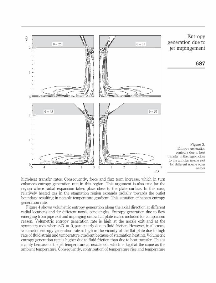
high-heat transfer rates. Consequently, force and flux term increase, which in turnenhances entropy generation rate in this region. This argument is also true for theregion where radial expansion takes place close to the plate surface. In this case,relatively heated gas in the stagnation region expands radially towards the outletboundary resulting in notable temperature gradient. This situation enhances entropygeneration rate.
Figure 4 shows volumetric entropy generation along the axial direction at differentradial locations and for different nozzle cone angles. Entropy generation due to flowemerging from pipe exit and impinging onto a flat plate is also included for comparisonreason. Volumetric entropy generation rate is high at the nozzle exit and at thesymmetry axis where r/D ¼ 0, particularly due to fluid friction. However, in all cases,volumetric entropy generation rate is high in the vicinity of the flat plate due to highrate of fluid strain and temperature gradient because of stagnation heating. Volumetricentropy generation rate is higher due to fluid friction than due to heat transfer. This ismainly because of the jet temperature at nozzle exit which is kept at the same as theambient temperature. Consequently, contribution of temperature rise and temperature
Figure 3.Entropy generation
contours due to heattransfer in the region closeto the annular nozzle exitfor different nozzle outer
angles
1E-0 7
1E-0
71E-07
1E-071E-07
1E-07
1E
-071
E-07
1E
- 07
5E-07
5E-0
7
5E-07
5E-07
5E
-07
5E
-07
5E-07
5E-07 5E-07
1E-06
1E
-06
1E
- 06
1E-06
1E-06
1E-0
6
1E-06
1E-061E-06
1E-0
6
1E-06
5E-06
5E-06
5E-0
6
5E-06 5E
-06
5E-06
5E 06
5E
-06
5E-06
5E-05
5E-0
5
5E-05
5E-05
5E 05
1E-0
71E
-07
1E-07
1E-07
1E-0
7
1E
-07
5E-0
7
5E-07
5E-0
7
5E-07
5E-07
5E
-07
5E
-07
1E-0
6
1E
-06
1E-0
6
1E-0
1E-0
6
1E-0
6
1E-06
1E-061E-06
5E
-06
5E-06
5E
-06
5E-0
6
5E-06
5E 06
5E-0
6
5E-0
5
5E-05
5E-0
5
5E-0
5
5E-055E-05
1E-0
71E
-07
1E-07
1E-071E-07
1E-07 1E-07
1E-0
7
5E-07
5E-07
5E-075E-07
5E
-07
5E-0
7
5E-07
1E-06
1E-0
6
1E
-06
1E-0
6
1E-0
6
1E-061E-06
5E
-06
5E-06
5E
-06
5E-06
5E-0
6
5E-06
5E-0
6
5E-0
5
5E-0
5
5E-05
5E-05
5E-05
0 001
1E-07
1E-07
1E-07
1E-0
7
1E-07
1E-07
5E-0
7
5E
- 07
5E-07
5E-07 5E-07
5E-0
7 5E-0
7
5E-07
1E-0
6
1E-0
61E
-06
1E-06
1E-0
6
1E-06
1E-061E-06
1E-0
6
1E
-06
1E-0
6
1E-06
5E-0
6
5E-06
5E-06
5E
-06
5E-0
6
5E
-06
5E-06
5E-0
65
E-0
6
E-065E-06
5E
-05
5E-05
5E-0
5
5E-0
5
5E-050 001
θ = 25 θ = 35
θ = 55θ = 45
x/D
0
1
2
0
1
2
012345r/D
0 1 2 3 4 5
Entropygeneration due tojet impingement
687

Figure 4.Volumetric entropygeneration rate for annularnozzles and pipe atvarious r/D locations anddifferent outer angles
r/D
= 0
.5
S''' g
en, f
rict
ion
r/D
= 4
.0r/
D =
1.0
r/D
= 0
.5r/
D =
2.5
S''' g
en, h
eat t
rans
fer
r/D
= 4
.0r/
D =
2.5
r/D
= 1
.0
x/D
0.0
0.5
1.0
1.5
2.0
25˚
35˚
45˚
55˚
pipe
r/D
= 0
.0
x/D
10–8
10–6
10–4
10–2
10–8
10–6
10–4
10–2
100
10–1
210
–10
10–8
10–6
10–1
010
–810
–610
–410
–12
10–1
010
–810
–610
–410
–12
10–1
010
–810
–610
–410
–12
10–1
010
–810
–610
–410
–410
–12
10–8
10–6
10–4
10–2
100
10–8
10–6
10–4
10–2
100
10–8
10–6
10–4
10–2
100
100
0.0
0.5
1.0
1.5
2.0
25˚
35˚
45˚
55˚
pipe
r/D
= 0
.0
HFF17,7
688

gradient on the entropy generation is due to heat generated during fluid friction andthermodynamic pressure rise because of the stagnation point flow. When comparingvolumetric entropy generation rates due to flow exiting the pipe and annular nozzle,they behave similarly along the axial direction, except along the symmetry axis wherer/D ¼ 0. In this case, annular nozzle generates high rate of entropy generation. This isdue to complex flow structure generated in the jet emerging from the nozzle, i.e. rate offluid strain increases at nozzle exit resulting in high rate of entropy generation.
Figure 5 shows total entropy generation rate due to heat transfer ad fluid frictionwith different nozzle outer angle as well as pipe. Entropy generation due to heattransfer and fluid friction is less for flow emerging from the pipe exit. This can beexplained in terms of rate of fluid strain developed in the flow field, which is less for thecase of pipe. Increasing nozzle cone angle enhances entropy generation due to bothfluid friction and heat transfer effects. This indicates that increasing nozzle outer coneangle increases the kinetic energy dissipation in the fluid. It should be noted thatincreases in temperature in the flow system is because of heat generated across theshear layers in the fluid. This is the indication of higher rate of entropy generationdue to fluid friction than that of heat transfer. Consequently, complex-flow structureenhances the kinetic energy loss in the flow system without significantly increasingtemperature.
6. ConclusionsEntropy generation in the flow system due to jet emerging from an annular nozzle andimpinging onto a flat plate is examined. The annular nozzle outer cone angle is variedin the simulations in order to investigate the effect of nozzle geometry on the entropygeneration. A jet emerging from a pipe and impinging onto a flat plate is also simulatedfor comparison reason. It is found that volumetric entropy generation rate increases atnozzle exit due to velocity distribution of flow emerging from the nozzle and complexflow structure generated in the vicinity of the nozzle exit. Entropy generation rate
Figure 5.Total entropy generationrate due to fluid friction
and heat transfer0.E+00
2.E–07
4.E–07
6.E–07
8.E–07
Pipe 25 35 45 55
NOZZLE ANLGE
S TO
TA
L D
UE
TO
HE
AT
TR
AN
SFE
R
0
0.002
0.004
0.006
0.008
0.01
S TO
TA
L D
UE
TO
FL
UID
FR
ICT
ION
Due to heat transferDue to fluid friction
Entropygeneration due tojet impingement
689

increases in the region of flat plate surface due to radial jet development from thestagnation zone. Volumetric entropy generation rate is higher due to fluid friction thanits counterpart corresponding to heat transfer. This is mainly because of the kineticenergy loss which is high in the flow system and heat generated by the shear flow,which is transferred to down stream by jet expansion. This in turn lowers thetemperature gradient and temperature rise in the fluid, particularly in the upstreamflow. Increasing nozzle outer angle enhances kinetic energy dissipation; consequently,nozzle geometry has significant effect on entropy generation rate.
References
Bejan, A. (1982), “Second-law analysis in heat transfer and thermal design”, Advances in HeatTransfer, Vol. 15, pp. 1-58.
Bejan, A. (1995), Entropy Generation Minimization, 1st ed., CRC Press, New York, NY.
Benocci, C. (1991), Introduction to the Modeling of Turbulence, 1991-02, Von Karman Institute forFluid Dynamics, Sint-Genesius-Rode, March.
Carrington, C.G. and Sun, Z.F. (1992), “Second law analysis of combined heat and mass transferin internal flow and external flows”, International Journal of Heat and Fluid Flow, Vol. 13No. 1, pp. 65-70.
Colucci, D.W. and Viskanta, R. (1996), “Effect of nozzle geometry on local convective heattransfer to a confined impinging air jet”, Experimental Thermal and Fluid Science, Vol. 13No. 1, pp. 71-80.
Dano, B.P.E. (2005), “Flow characteristics and heat transfer performances of a semi-confinedimpinging array of jets: effect of nozzle geometry”, International Journal of Heat and MassTransfer, Vol. 48, pp. 691-701.
Drost, M.K. and White, M.O. (1991), “Numerical predictions of local entropy generation in animpinging jet”, Journal of Heat Transfer, Vol. 113, pp. 823-9.
Elkaim, D., Reggio, M. and Camarero, R. (1992), “Simulating two-dimensional turbulent flowby using the k-e model and the vorticity-stream function formulation”, InternationalJournal for Numerical methods in Fluids, Vol. 14, pp. 961-80.
Hiroshi, M. and Akira, Y. (1989), “Heat transfer by the annular impinging jet”, ExperimentalHeat Transfer, Vol. 2, pp. 1-12.
Hogg, S. and Leschziner, M.A. (1989), “Second-moment-closure calculation of strongly swirlingconfined flow with large density gradients”, International Journal of Heat and Fluid Flow,Vol. 10 No. 1, pp. 16-27.
Huang, L. and El-Genk, M.S. (1994), “Heat transfer of an impinging jet on a flat surface”,International Journal of Heat and Mass Transfer, Vol. 37 No. 13, pp. 1915-23.
Launder, B.E. (1989), “Second-moment closure and its use in modelling turbulent industrialflows”, International Journal for Numerical Methods in Fluids, Vol. 9, pp. 963-85.
Lee, D., Greif, R., Lee, S.J. and Lee, J.H. (1995), “Heat transfer from a flat plate to a fully developedaxisymmetric impinging jet”, ASME Journal of Heat Transfer, Vol. 117, pp. 772-6.
Lytle, D. and Webb, B.W. (1994), “Air jet impingement heat transfer at low nozzle-platespacings”, International Journal of Heat and Mass Transfer, Vol. 37 No. 12, pp. 1687-97.
Mahmud, S. and Eraser, R.A. (2003), “The second law analysis in fundamental convective heattransfer problems”, International Journal of Thermal Sciences, Vol. 42, pp. 177-86.
Mohanty, A.K. and Tawfek, A.A. (1993), “Heat transfer due to a round jet impinging normal to aflat surface”, International Journal of Heat and Mass Transfer, Vol. 36 No. 6, pp. 1639-47.
HFF17,7
690

Mukherjee, P., Biswas, G. and Nag, P.K. (1987), “Second-law analysis of heat transfer in swirlingflow through a cylindrical duct”, ASME Journal of Heat Transfer, Vol. 109, pp. 308-13.
Patankar, S.V. (1980), Numerical Heat Transfer, McGraw-Hill, New York, NY.
Shuja, S.Z., Yilbas, B.S. and Budair, M.O. (2005), “Influence of conical and annular nozzlegeometric configurations on flow and heat transfer characteristics due to flowimpingement onto a flat plate”, Numerical Heat Transfer, Part A, Vol. 48, pp. 917-39.
Versteeg, H.K. and Malalasekera, W. (1995), An Introduction to Computational Fluid Dynamics.The Finite Volume Method, Longman Scientific and Technical, Harlow.
Yang, G., Choi, M. and Lee, J.S. (1999), “An experimental study of slot jet impingement cooling onconcave surface: effects of nozzle configuration and curvature”, International Journal ofHeat and Mass Transfer, Vol. 42 No. 12, pp. 2199-209.
Yilbas, B.S., Shuja, S.Z. and Budair, M.O. (1999), “Second law analysis of a swirling flow in acircular duct with restriction”, International Journal of Heat and Mass Transfer, Vol. 42,pp. 4027-41.
Corresponding authorB.S. Yilbas can be contacted at: [email protected]
Entropygeneration due tojet impingement
691
To purchase reprints of this article please e-mail: [email protected] visit our web site for further details: www.emeraldinsight.com/reprints