CATALOGING NON- TRADITIONAL (MOSTLY ONLINE) MATERIALS The Whys and Hows.

The Hows and Whys of Ethernet Networks in Substations
Darold Woodward Schweitzer Engineering Laboratories, Inc.
Presented at the 3rd Annual Western Power Delivery Automation Conference
Spokane, Washington April 10–12, 2001

1
THE HOWS AND WHYS OF ETHERNET NETWORKS IN SUBSTATIONS
Darold Woodward, PE Schweitzer Engineering Laboratories
Pullman, WA USA
This paper provides an introduction to Ethernet networking in electrical substations. In addition to basic Ethernet network terms and concepts, it addresses specific issues related to Ethernet networks in substations.
ETHERNET Robert Metcalfe and several other research partners invented Ethernet networking in the Xerox Palo Alto Research Center (Xerox PARC) [1]. In 1972 they constructed the Alto Aloha Network connecting several Xerox Alto computers. Metcalfe, David Boggs, Charles Thacker, and Butler Lampson filed the patent for the Ethernet network in 1975. The drawing shown in Figure 1 is similar to one Metcalfe used in a presentation explaining the Ethernet network concept.
Terminator
Tap
Transceiver
I CInterface Cable
InterfaceController
Station
DWG: 6115001
The Ether
Figure 1 Ethernet Network Illustration
Similar to the luminiferous ether used by early investigators to explain how light and other electromagnetic waves travel across a vacuum, the network acts as the ether allowing transmission of messages among computers.
Today Ethernet is the dominant networking technology used in office and home environments. Because Ethernet networks are inexpensive and fairly well understood, their use is quickly becoming popular for industrial and utility applications including substation automation networks.
Ethernet networks were not developed specifically for operation in substations and other harsh environments. Why is there so much interest in applying Ethernet networks in these locations? The answer is similar to why personal computers are now used in many industrial and power

2
system applications. Ethernet is so popular in other applications that it is simpler to employ and enhance Ethernet than to create something new.
Only 15 years ago, most Human Machine Interfaces (HMIs) operated on dedicated mainframe computers with terminals rather than the legion of personal computers that is used today. Early personal computer HMIs used custom operating systems dedicated to HMI operation. While dedicated systems are more stable and reliable, today�s systems often cost from 10 to 1 percent of the expense of dedicated single-purpose systems.
Both industrial and utility networking experts are moving forward accepting the limitations of Ethernet networks and solving the problems associated with Ethernet networks. Advances in computing power and network technology allow us to take advantage of the popularity and availability of Ethernet networking equipment and solutions.
There are two excellent resources on the Internet [1], [2] where you can get an introduction to Ethernet networks.
OSI SEVEN-LAYER MODEL No discussion of networking technology would be complete without an introduction to the International Standards Organization (ISO) Open Systems Interconnect (OSI) seven-layer model. The model represents networking (both software and hardware) in an individual network node by dividing tasks into layers that perform specific functions. The OSI model provides a good way to organize this discussion of Ethernet networking. The OSI model for network operation on two network nodes is shown in Figure 2.

3
Application
Presentation
Session
Transport
Network
Data Link
Physical
Logical Connection Application
Presentation
Session
Transport
Network
Data Link
Physical
Logical Connection
Logical Connection
Logical Connection
Logical Connection
Logical Connection
Physical Connection
LayerNumber
7
6
5
4
3
2
1
NetworkNode 1
NetworkNode 2
DWG: 6115002 Figure 2 OSI Seven-Layer Model
In the OSI model, each layer (for example, the data link layer) communicates via a logical connection with the same layer in the other device. Network operation is more complex. Application data, such as characters in a Telnet terminal session or UCA2 GOMSFE model data, pass down through the layers and then across the physical medium. Each layer adds some information to the message and forwards it down to the next layer.
Ultimately, the message reaches the lowest (physical) layer, and is sent across the physical connection to the second network node. Here the process operates in reverse. Each layer removes and uses the layer-specific information, and passes the remaining information up the chain until the original data become available to the application user.
As long as there is a defined interface between layers, one layer can be replaced by another that conforms to the interface specification. For example, Ethernet networks can operate over many different media, from wire cables, to fiber-optic cables, to wireless radio connections. The physical layer can be replaced as long as the interface remains unchanged.
Initially codified in the Dec-Intel-Xerox (DIX) standard, Ethernet networking standards are now defined by the Institute of Electrical and Electronic Engineers (IEEE) standard 802.3. Ethernet networks are defined by the lowest two layers of the OSI model, physical and data link. Ethernet by itself is not capable of moving data among devices without the upper layers.

4
ETHERNET PHYSICAL AND DATA LINK LAYERS Each standard physical layer and corresponding data link layer has a designator (e.g., 10BASE-T) that identifies the layer specifications. The most popular physical and data link layer combinations for Local Area Networks (LANs) within a single building are fiber optics (10BASE-FL and 100BASE-FX) and twisted-pair metallic (10BASE-T and 100BASE-TX). For general use networks, 10 Mbps and 100 Mbps are the most popular data transmission speeds.
As data demands on networks have increased, 100 Mbps networks have become more popular. The actual network loading for a given offered load is about 10 times lower on 100 Mbps networks than on 10 Mbps networks, reducing collisions and network latencies.
Coaxial Cable
The original Ethernet network developed at Xerox PARC was a 2.94 Mbps network that used heavy coaxial cable (coax), commonly called Thicknet. Later developments of a lighter, less expensive coax wiring were called Thinnet. Coax networks are true multidrop networks. The main trunk cable connects each node to the next. A tap device at each node provides a place for the node to access the trunk cable. While multidrop networks are simple to imagine, they have two principal drawbacks.
First, multidrop cable systems can fail if a single section of the trunk cable is damaged or severed. Second, it is difficult and expensive to add new nodes. The tap length, for example, is limited. If you want to add a new node 100 feet from the existing trunk cable, you may have to run 100 feet of trunk cable to the new node and 100 feet of trunk cable back to the existing trunk cable. The resulting configuration is shown in Figure 3.
... ...Tap Cable
Trunk Cable
DWG: 6115003
New Node
Figure 3 Adding a Node to a Multidrop Network
Coax is expensive and is not available unless you add it to the building (a messy and expensive effort) or install it during building construction. As stated above, adding a node to an existing multidrop coax network is expensive if you forget one and add it later.
5
Twisted-Pair Cable
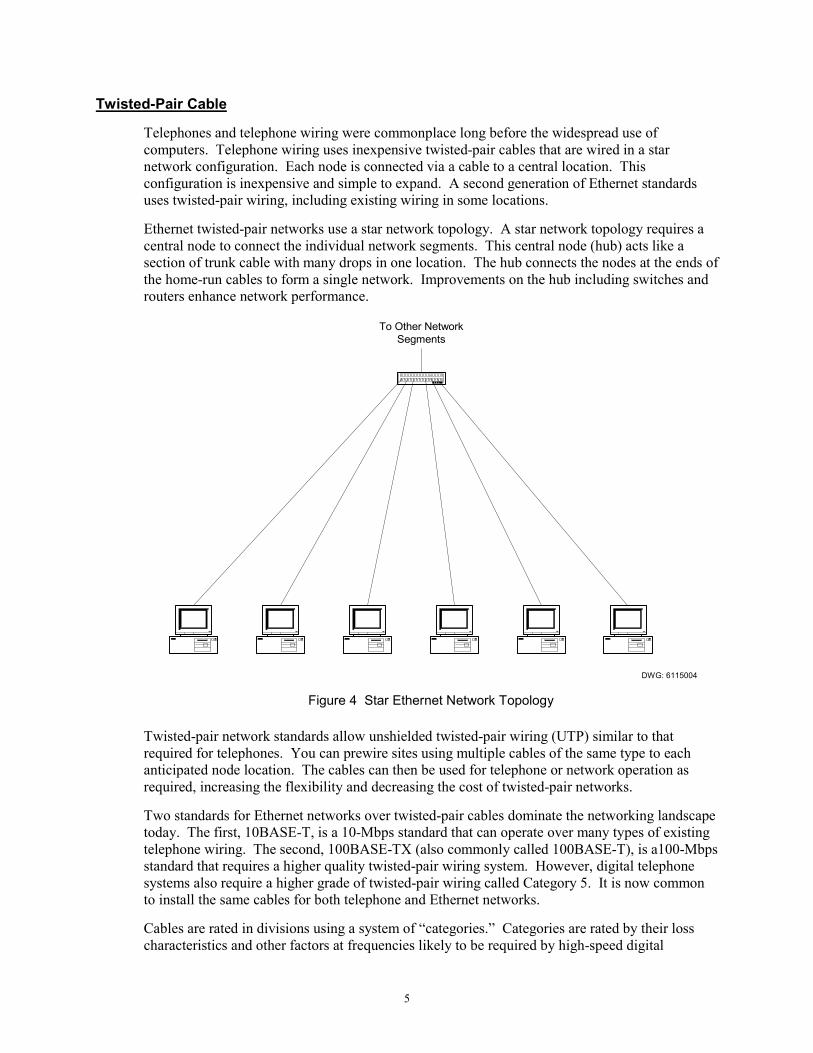
Telephones and telephone wiring were commonplace long before the widespread use of computers. Telephone wiring uses inexpensive twisted-pair cables that are wired in a star network configuration. Each node is connected via a cable to a central location. This configuration is inexpensive and simple to expand. A second generation of Ethernet standards uses twisted-pair wiring, including existing wiring in some locations.
Ethernet twisted-pair networks use a star network topology. A star network topology requires a central node to connect the individual network segments. This central node (hub) acts like a section of trunk cable with many drops in one location. The hub connects the nodes at the ends of the home-run cables to form a single network. Improvements on the hub including switches and routers enhance network performance.
To Other NetworkSegments
DWG: 6115004 Figure 4 Star Ethernet Network Topology
Twisted-pair network standards allow unshielded twisted-pair wiring (UTP) similar to that required for telephones. You can prewire sites using multiple cables of the same type to each anticipated node location. The cables can then be used for telephone or network operation as required, increasing the flexibility and decreasing the cost of twisted-pair networks.
Two standards for Ethernet networks over twisted-pair cables dominate the networking landscape today. The first, 10BASE-T, is a 10-Mbps standard that can operate over many types of existing telephone wiring. The second, 100BASE-TX (also commonly called 100BASE-T), is a100-Mbps standard that requires a higher quality twisted-pair wiring system. However, digital telephone systems also require a higher grade of twisted-pair wiring called Category 5. It is now common to install the same cables for both telephone and Ethernet networks.
Cables are rated in divisions using a system of �categories.� Categories are rated by their loss characteristics and other factors at frequencies likely to be required by high-speed digital

6
networks. Category 3 is the lowest category that will support 10BASE-T. Category 5 is required for the 100-Mbps data speeds of 100BASE-TX and is also acceptable for typical digital telephone networks. Standards for Category 6 and beyond are under development and are intended to support future networking applications at speeds of 1 Gbps and above.
Unfortunately, while UTP cables are inexpensive and simple to apply in an office environment, they can be a problem in other environments. For example, offices typically do not contain strong sources of radio frequency interference (RFI) because of the shielding provided by office buildings and the lack of strong RFI sources within the building.
Utility and industrial installations, however, often contain strong internal sources (hand-held radios, variable frequency drives, welders, etc.) and may not be well shielded from external sources including radio transmitter towers. Substations also include control wiring that typically is not shielded and can induce voltages in adjacent wiring.
You can mitigate many of the problems associated with UTP cables by enclosing them in conduit or other fully enclosed ferrous raceways. Conduits, however, change the impedance characteristics of the cable, increasing delay and signal loss [3]. Another strategy sometimes employed in industrial installations is to use shielded twisted-pair (STP) cables.
STP cables include an overall shield that reduces RFI and helps protect equipment connected to the cable from electrostatic discharge (ESD). While Ethernet network STP cabling is considered rare overall, it is relatively common in industrial and other high-noise environments where UTP cables are not acceptable.
You should never run any type of metallic communications cable from the substation control house to equipment in the substation yard. The ground potential differences experienced during a fault in the substation can subject your equipment to damaging voltages and currents, especially in cables with shields that are grounded at both ends.
In a substation control house, many of these risks are decreased, but the noise from control and instrumentation circuits and circuit breakers in metal-enclosed switchgear can disrupt networks. Even with shielding and physical separation from other cables and wiring, metallic cables with shields provide paths for current to flow from ground potential differences, DC faults, and other stray electricity. The only sure protection from these problems is a cable system that is unaffected by electrical and electromagnetic interference.
Fiber-Optic Cable
Fiber-optic cable systems provide two principal benefits. First, the signals within fiber-optic cables are immune to RFI and electrostatic interference that can disrupt communication on metallic cables. Second, fiber-optic cables can have an all-dielectric (nonconducting) construction. This means that you can run fiber-optic cables outside of the control house to provide robust and reliable communication without the threat of damaging critical equipment at the ends of the communications circuit.
Where twisted-pair wiring uses two pairs, one for transmit and one for receive, fiber-optic cable systems use a pair of fibers, one for transmit and one for receive. Fiber-optic cable systems also require a central node or hub that combines the point-to-point fiber-optic cable segments into one logical network. The most popular fiber-optic Ethernet network standards are 10BASE-FL and 100BASE-FX, 10 Mbps and 100 Mbps, respectively.

7
Fiber-optic cable is more expensive than metallic cable. However, shielding measures for twisted-pair cables and installation labor are significant construction costs. You must consider the installed cost of the network to properly evaluate the impact of your choice of network physical medium.
Hubs, network adapters, and other fiber-optic networking equipment are more expensive than equipment used for twisted-pair networks. In applications where high reliability is required and protection of mission-critical equipment is essential, fiber-optic cable systems are often worth the added expense.
Cost Comparison of Cable System Components
Table 1 compares the cost of fiber-optic cable and accessories that would be required in a typical substation Ethernet network.
Table 1 Comparison of Twisted-Pair and Fiber-Optic Network Component Cost
Component Twisted-Pair Fiber-Optic
1-meter patch cable $7.00 UTP $35.00
5-meter patch cable $12.00 UTP $45.00
Bulk indoor cable $0.12 per foot $0.60 per foot (single pair)
Cable termination connector $1.60 $12.00
Substation hardened Ethernet adapter for protective relay
$1100.00 $1500.00
PC Ethernet adapter $73.00 $340.00
Industrially hardened hub (8 port) $800.00 $3400.00
Ethernet Frames
All data exchanged on Ethernet networks travel within Ethernet frames. The Ethernet frame is the outer wrapper for all of the upper-layer information and application data sent across the network. All Ethernet traffic travels within Ethernet frames that include a source address, destination address, data payload (as many as 1500 bytes), and a checksum.
There is a slight difference between the frames defined in Ethernet II (evolved from DIX standard) and IEEE 802.3 frames. The frames can coexist on the same network, but all devices must include compatibility with Ethernet II frames and should be compatible with IEEE 802.3 frames.
Media Access
With Ethernet networks, the time required for data to move across the network is not guaranteed. The Ethernet network interface of a device may drop data packets if network traffic is too high. This nondeterministic timing performance must be considered for time-critical applications such as peer-to-peer protection and control messages. In a deterministic system, all events occur with completely predictable timing and sequence. A basic understanding of Ethernet media access rules is important for understanding why Ethernet networks are not deterministic.

8
High-speed bus and multidrop networks can operate over many different physical connections or media (for example, fiber-optic cable or twisted-pair cable). Network operation requires that all devices be connected to a common medium. All network nodes use the same signaling method.
Because only one node at a time can send data successfully, multidrop and bus networks must have media access rules to move data effectively across the network. In networks similar to Modbus® there is a single master device. All network traffic is either the master requesting information or a response to the master.
A second method of media access control is token rotation. A special message, or token, is controlled by a master or forwarded from each peer to the next. Each node gets the token, acts as the network master, and sends messages to other devices. For lightly loaded networks, token rotation is inefficient because nodes that have no pending network operations still receive the token. A network error may also corrupt or destroy the token message, causing the network to generate a new token. Token generation is very slow compared to normal network operations.
In order to overcome the drawbacks of both master-based and token rotation media access control, Ethernet networks use a system called Carrier Sense Multiple Access/Collision Detection (CSMA/CD). In this system, any node can send data at any time. In order for a node to send data, it must first listen for a carrier to determine that no other node is transmitting. Collisions occur when two nodes find the network available and transmit data at the same time. Ethernet network nodes have mechanisms to detect collisions and take additional steps to resolve the collision and transmit messages.
When a collision occurs on an Ethernet network, the sending nodes stop transmitting and insert a delay before listening and starting the transmission sequence again. This process is called back-off. If collisions persist (more than 16 times), the node eventually will abandon the outgoing message and upper protocol layers must cope with the loss of data.
Because of CSMA/CD operation, communication transmission times on an Ethernet network are not deterministic. Ethernet networks do not have guaranteed delivery times or guaranteed performance. For small, lightly loaded networks, CSMA/CD is efficient and fast. For large networks or during periods of sustained high network traffic, data transport times can become longer, highly variable, and data packets may be lost.
If you look closely at CSMA/CD operation, you will also find that it does not give priority to the oldest, or most delayed, information. If several nodes are contending for network access and a new node attempts to send data, the odds favor the message from the new node going out first. This has been termed �channel capture� and in extreme cases leads to the �packet starvation effect� (PSE) [4].
In heavily loaded networks, as the channel is captured, the older messages eventually may be abandoned when the maximum of 16 retires is consumed. This leads to more application layer messages as lost data are repeated. The collisions and retransmissions lead to increased network loading. The high loading and PSE lead to excessive network latencies or complete network breakdown.
One study [4] found that message delays for highly loaded networks became unacceptable for data that required deterministic, low latency delivery. For example, a network with 40 nodes and an offered load (requested network loading of traffic among nodes) of 71.9 percent (much higher than normal network operation) had an average latency of 3.4 ms. The average is acceptable for protection control messages, but the variation in latency is unacceptable. The standard deviation was 12.6 ms with many observed delays of over 100 ms and a maximum approaching 1000 ms.

9
While these tests were performed at what some would call unrealistically high loading levels, it is important to note that Ethernet does not include mechanisms to limit loading. The test conditions include three streaming video channels (65.4 percent offered load) and data traffic among nodes (6.5 percent offered load). The test case could easily represent what happens when you (as an experiment) attempt to use the Ethernet network to send security camera video across the network to the SCADA control center as well as real-time monitoring data.
For most measurement and status data collection, the nondeterministic performance of Ethernet networking is not a cause for concern. For time-sensitive data such as peer-to-peer protection and control, Ethernet network performance, loading, and architecture are important network design considerations. An Ethernet switch, for example, can greatly improve Ethernet determinism and performance for heavily loaded networks. See Ethernet Network Components for more discussion on the components of Ethernet networks.
Network Data Transfer Rate vs. Throughput
It is also very important to recognize that the data transfer rate on your network does not directly equate to an increase in performance or throughput. If you are used to a 9600 bps dial-in connection, you might expect a 10 Mbps Ethernet network to transfer data over 1000 times faster. In reality, high-speed data transmission also includes an increase in message overhead, and throughput is limited by the message processing capabilities of the network nodes.
Testing performed for a paper presented at the 2000 Western Power Delivery Automation Conference [5], compared a 9600 bps multidrop Modbus network to a 10 Mbps UCA2 network. The manual open command from an operator at an HMI reached the output contacts of an IED in 1.446 seconds over the Modbus network and 0.021 seconds over the UCA2 network, less than 70 times faster on Ethernet. The round-trip time from operator input to display on the HMI screen was 3.106 seconds and on the UCA2 Ethernet network it was 0.389 seconds, less than 8 times faster on Ethernet.
PROTOCOL STACKS The upper-layer functions are gathered together and known as a protocol stack. Most of the protocol stack services are in Layers 3 and 4, but protocol stacks are often part of a protocol suite that includes services for higher layers. The most popular protocol suite is TCP/IP and UDP/IP (often called just TCP/IP).
TCP/IP and UDP/IP
TCP/IP and UDP/IP are the network stacks that have gained fame as the foundation of the Internet. Figure 5 is a diagram of the Internet protocol suite and components. TCP/IP, UDP/IP, and application layer protocols (FTP, SMTP, Telnet, etc.) are collectively known as the Internet protocol suite.

10
RIP OSPF ICMP
SNAP
LLC
ARPRARP
IP
UDPTCP
NetBIOS
SMB RCMD CMOT SNMP DNSTFTP
FTPTelnetSMTP
Application
Presentation
Session
Transport
Network
Logical Link
Ethernet�Token RingPhysical
DWG: 6115005 Figure 5 TCP/IP and UDP/IP Diagram [6]
TCP/IP and UDP/IP are separate stacks, but the common IP foundation tends to keep them together. Most stack software that supports TCP or UDP supports both. Internet Protocol (IP) is a layer that provides basic packet transmission through addressing, fragmentation of packets, packet time-outs, and several other features.
User Datagram Protocol (UDP) consists of layers above IP and completes a simple protocol for exchanging packets of information between network nodes. UDP adds port numbers and checksums to IP. Unlike TCP, UDP does not use connections, which avoids the handshaking required to verify that the receiving node is available or the message has reached its destination.
Transmission Control Protocol (TCP) adds streams, reliable delivery, network adaptation, and flow control to IP to create a fairly robust connection-oriented protocol for exchanging packets on the network. Because TCP includes routing and connections, it is used for most point-to-point data exchange tasks.
11
OSI
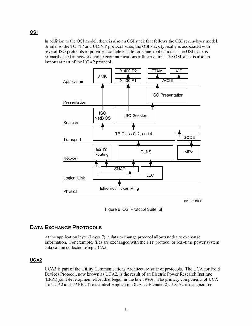
In addition to the OSI model, there is also an OSI stack that follows the OSI seven-layer model. Similar to the TCP/IP and UDP/IP protocol suite, the OSI stack typically is associated with several ISO protocols to provide a complete suite for some applications. The OSI stack is primarily used in network and telecommunications infrastructure. The OSI stack is also an important part of the UCA2 protocol.
ES-ISRouting CLNS
ISODETP Class 0, 2, and 4
ISONetBIOS
Session
Transport
Network
Logical Link
Ethernet�Token RingPhysical
DWG: 6115006
SNAP
ISO Session
ISO Presentation
Application
Presentation
SMB
<IP>
LLC
X.400 P2
X.400 P1
FTAM VIP
ACSE
Figure 6 OSI Protocol Suite [6]
DATA EXCHANGE PROTOCOLS At the application layer (Layer 7), a data exchange protocol allows nodes to exchange information. For example, files are exchanged with the FTP protocol or real-time power system data can be collected using UCA2.
UCA2
UCA2 is part of the Utility Communications Architecture suite of protocols. The UCA for Field Devices Protocol, now known as UCA2, is the result of an Electric Power Research Institute (EPRI) joint development effort that began in the late 1980s. The primary components of UCA are UCA2 and TASE.2 (Telecontrol Application Service Element 2). UCA2 is designed for

12
communication with substation IEDs. TASE.2, also known as ICCP (Inter-control Center Communication Protocol), is designed to move data between real-time databases.
All of the UCA protocols are designed in a layered approach with complete network independence at the highest modeling layer. To speed implementation and aid in interoperability, the demonstration projects and specifications incorporate specific stack and network layers.
Both TASE.2 and UCA2 are based on an underlying communications protocol, Manufacturing Messaging Specification (MMS). MMS is an industrial automation protocol developed largely by General Motors which has served as a research and development center for advanced technologies in industrial automation. While MMS is no longer in wide use in the industrial automation environment, it is a capable protocol that serves as the foundation for both UCA2 and TASE.2.
UCA2 is a profile for object-oriented communication with substation IEDs using MMS. Common Application Service Models (CASM) defines how objects interact with network services (MMS). GOMSFE is the object model specification for UCA2. Figure 7 illustrates how the components of UCA2 work and how network stack and physical network layers combine as a complete UCA2 protocol.
CASM
GOOSE
GOMSFE
MMS
DWG: 6115007
OSI
OSI
TCP/IP
Ethernet
Figure 7 UCA2 Components
The protocol stack layer of UCA2 implementations that is being used today is a combination of OSI and TCP/IP. You can use purely the OSI stack or lower layers of the TCP/IP stack combined
13
with upper layers of the OSI stack. Most implementations include the components required to operate on either stack configuration.
The specifications and standards for UCA2 are complete from a working document perspective but are not part of a ratified standard. The working documents were developed through a series of EPRI demonstration projects and technical meetings. The most recent complete GOMSFE specification is 0.91. Several other documents describe CASM and other facets of UCA2. EPRI does not act as a standards organization, and at this time there is no single specification group and no way to request a set of current UCA2 documents. Two parallel efforts in standards boards are underway to develop and ratify working standards.
The International Electrotechnical Commission (IEC) is working on a standard under the label IEC 61850 for GOMSFE models. It is unclear whether the IEC project will include the CASM, MMS, and Ethernet network components as the only implementation or whether mapping to other lower layers including the IEC 61870 protocols will be included.
P1525 is a standards effort for substation networks within the IEEE. It is unclear at this time whether P1525 work will complement the IEC work or take a different course. Many of the early proponents of UCA2 are calling for the EPRI, IEEE, and IEC efforts to culminate in a �harmonization� where all specifications are made compatible and interoperable. Currently, there is no timetable for harmonization or coordination of efforts among these groups. While a cohesive movement to standardize UCA2 does not exist, several manufacturers are implementing UCA2 using the EPRI working documents.
GOMSFE
GOMSFE is an object model for collecting measurement and status data from substation IEDs. GOMSFE uses an object-oriented abstract to create standard definitions for representing meters, protective relays, and other devices on UCA2 networks. Unlike previous generations of protocols, UCA2 does not rely on the concepts of indices or registers. GOMSFE organizes data into object models called models or bricks.
GOMSFE describes multifunction devices with several models, each describing one function. An example of this is a protective relay. A relay may contain metering data that populate a multiphase metering model. The protective relay may also function as a circuit breaker interface with a model for a circuit breaker controller.
GOMSFE models consist of standard pieces of data with standard names built from a set of standard data types. For example, the polyphase measurement brick (MMXU) includes A-phase current. Table 2 lists the objects in the MX functional component of the MMXU model. The A-phase current is part of the object MMXU$MX$A which is indicated as being of class WYE.

14
Table 2 MMXU Model MX Functional Component [7]
FC
Object Name
Class
rwec
mo
Description
MX V WYE r o Voltage on phase A, B, C to G
PPV DELTA r o Voltage AB, BC, CA
A WYE r o Current in phase A, B, C, and N
W WYE r o Watts in phase A, B, C
TotW AI r o Total Watts in all 3 phases
VAr WYE r o VArs in phase A, B, C
TotVAr AI r o Total VArs in all 3 phases
VA WYE r o VA in phase A, B, C
TotVA AI r o Total VA in all 3 phases
PF WYE r o Power Factor for phase A, B, C
AvgPF AI r o Average Power Factor of all 3 phases
Ang WYE r o Angle between phase voltage and current
Hz AI r o Power system frequency
FltMagA WYE r o Fault Magnitude in phase A, B, C, N
In the �rwec� column of Table 2, we see that the phase currents are read-only. The measurements are also shown as optional in the �m/o� column. This means that devices that do not have this data will not include the phase current object. Type WYE is defined in a separate table as shown in Table 3.
Table 3 Common Class Type WYE [7]
Name Data Type m/o
PhsAi INT16S o
PhsAf FLT32 o
PhsBi INT16S o
PhsBf FLT32 o
PhsCi INT16S o
PhsCf FLT32 o
Neuti INT16S o
Neutf FLT32 o
q BSTR16 o
t BTIME6 o

15
Looking for the measurement for A-phase, we see PhsAi and PhsAf of types INT16S and FLT32, respectively, that are optional. If the device has a 16-bit signed integer measurement, PhsAi will be available, and if the measurement is an IEEE 32-bit floating point, PhsAf will be available. At the bottom of the table, q is a string of 16 bit values that is used for data quality flags, and t is a timestamp representing when the measurement was collected. If our example device has the floating-point measurement of A-phase current, we could write the �flattened� reference to the value as MMXU$MX$A$PhsAf.
While this is a simple process, it is a time-consuming one. A feature called �self-description� speeds the process significantly. A standard MMS browser can request a description of the data contained in a UCA2 device and present that description to you on a computer screen. You can then point-and-click to the value of interest.
Standard object models alone do not allow individual manufacturers to innovate and add new features. Because of this potential limitation, GOMSFE allows for the extension of models and the creation of custom models. Custom models are also included in the self-description process so that you can use a browser to discover what is available on a node-by-node basis.
GOMSFE also uses a high-level organizational structure called domains. All UCA2 devices have at least one domain called a logical device and can include either more logical devices or more domains. The models are grouped in the domains.
Although not universally implemented, a mechanism for reporting data changes and time-stamped data is included in UCA2. A generic object for moving large items called a Binary Large Object (BLOB) is available for the transfer of files and other data not used by the UCA2 host but collected for other purposes.
GOOSE
GOOSE is part of the GOMSFE model GLOBE and also is an independent message system. UCA2 IEDs use GOOSE messages for event-driven peer-to-peer communication and control. Each UCA2 device sends a GOOSE message when an internal data-change event occurs. A data-change event occurs when a monitored point changes state, for example, from one to zero or from zero to one. Event-driven messages limit network traffic and improve response speed by sending messages only when data-change events occur. This is a significant improvement over polling mechanisms that burden the network even when no new data values are available.
In addition to the event-driven messages, UCA2 devices send GOOSE messages at a default rate of once every minute. Devices that receive GOOSE messages use the default rate messages to track the status of GOOSE senders and collect initial values when joining the network.
Each GOOSE message contains a text ID name of the GOOSE sender and a special Ethernet multicast destination address. UCA2 devices use the Ethernet multicast destination addresses to filter incoming GOOSE messages. Each device accepts and processes only messages containing information it is configured to use.
Each GOOSE message includes a Hold Time value that defines how long to consider the message data valid. When the hold time expires, the recipient of the GOOSE message can take appropriate action based on the information that messages from the GOOSE sender are no longer reaching the recipient.

16
DNP 3.00
In 1998 a paper presented to the Distributed Network Protocol (DNP) User�s Group [8] summarized earlier work with DNP over Ethernet networks and proposed several solutions. Although the document has not been ratified officially as part of the DNP standards, it stands as the working specification for many implementations of DNP 3.00 over Ethernet networks.
The document contains several key recommendations about DNP 3.00 operation of LAN and Wide Area Network (WAN) links. The most significant recommendations for the average end user are listed below:
• DNP will use the TCP/IP and UDP/IP protocol suite also called �The Internet Protocol Suite.�
• Ethernet is the recommended physical layer, but the recommended implementation will function over any link where the TCP/IP and UDP/IP protocol suite is present.
• All devices must support messaging through both TCP (connection oriented) and UDP (without connections) mechanisms.
• DNP layers are retained and supplement the network protocol layers so that major restructuring of DNP is unnecessary.
DNP 3.00 uses an object-oriented system that is not as complex as the one used for UCA2. Data types and requests are specified as DNP objects. Data objects specify types rather than specific data, so there is no standard way to request the A-phase current as in the UCA2 example above. If there can be more than one instance of an object, there is an index that makes each instance unique. Objects are used for shorthand data requests, specific data types, and operations such as control and event buffer collection.
Industrial Protocols
Several of the most popular industrial integration protocols are either running over Ethernet networks or are being prepared for operation over Ethernet networks. For example, Modbus TCP is Modbus for use over TCP/IP networks [9]. Other industrial protocols, including ControlNet®, Profibus, and Foundation Fieldbus, are migrating to Ethernet networks.
It is important to consider this work when you plan to use Ethernet in power system applications. The office environment has made technologies inexpensive and available for industrial applications and in cases where office-grade equipment is not adequately robust or rugged. Office-grade equipment provides a foundation for the understanding and development of appropriate industrial Ethernet network components. Similarly, industrial Ethernet networks serve as an excellent basis and proving ground for products and technologies that will find their way into substation Ethernet networks.

17
One of the best sources for information about industrial Ethernet networking is the web site http://ethernet.industrial-networking.com/. Based in the U.K., the web site is the on-line version of �The Industrial Ethernet Book,� a quarterly magazine-style publication that includes informative articles, lists of suppliers, and sources for information about industrial Ethernet networks.
Because few industrial Ethernet network protocols have been applied in substation Ethernet applications, they will not be considered in subsequent discussions of the technologies that you should consider when designing a substation Ethernet network.
ETHERNET NETWORK COMPONENTS There are several components required to build an Ethernet network. The paragraphs below list the essential equipment and provide some information about each. Figure 8 shows an Ethernet network with each of the listed devices indicated.
...
... ...
NetworkNode
NetworkAdapter
Hub
Switch
Router
To OtherLANs
...
DWG: 6115008 Figure 8 Ethernet Network Components
Network Node
A network node is a device on the network that does intelligent data processing or data generation. Network nodes can be classed as masters or slaves, clients or servers, and peers to describe the data flow between the nodes.

18
Network Adapter
Each device on an Ethernet network must include a physical interface to the standard Ethernet network. This interface is often called an adapter, a network card, or a network interface card (NIC). Even if the NIC is an integral part of the device, it must be there in order to be a part of the Ethernet network.
Each Ethernet interface has an Ethernet media access control (MAC) layer address that is assigned at the factory. Each manufacturer registers a range of addresses and, during manufacture, programs the interface to use an address. This means that every Ethernet network device has a unique address that is used in Ethernet frames.
Hubs
A hub is a device that acts like a trunk cable with very short segments that connect each node cable to the network. A hub repeats all incoming network traffic to all nodes. An uplink connection allows the hub to send data up to other hubs, switches, or routers. Hubs are an easy and inexpensive way to connect many devices to an Ethernet network.
Hubs are primarily passive devices. If a node fails and sends a continuous stream of error data onto the network, the hub repeats the error data to all network nodes. One advantage of hubs is that they are less complex, and therefore quite reliable, compared to switches and routers [10].
Switches
A switch acts as a hub, connecting nodes to form a network that operates logically as a multidrop network. In addition to repeating data, however, the switch decodes some parts of Ethernet messages and directs traffic on an Ethernet network.
One method for avoiding message collisions on an Ethernet network is to limit the number of network nodes. A group of nodes that shares a common medium is called a collision domain. When there are fewer nodes in a collision domain, fewer collisions occur, and the Ethernet network operates more deterministically and efficiently.
A switch reduces the collision domain of each node to the ultimate minimum�two nodes. A switch decodes incoming traffic from each network node and directs network traffic. The switch drastically reduces the number of message collisions, greatly improving Ethernet network performance.
While switches are less reliable than hubs, the increased Ethernet network performance offsets the decreased network reliability. Switches operate at the lowest layers (physical and data link layers) of Ethernet networks and are independent of the network stack or application protocol.
Routers
A router operates similarly to a switch. The difference is that routers keep messages in a local network and send out only messages that need to leave the local network. The router contains tables of how to route messages and decodes some of the Layer 3 or stack information to direct messages. Because routers operate at higher protocol layers than switches and hubs, you must select routers that are compatible with the protocol stacks on your network.

19
Routers do not forward Ethernet broadcast messages, GOOSE messages, for example. Ethernet broadcast messages are not intended for nodes outside of the local network. Some more advanced routers act as network bridges that allow you to route nonroutable protocols like GOOSE. You must be very careful if you route broadcast messages because you may drastically increase the traffic across low-bandwidth links between networks. High traffic can significantly diminish the throughput of internetwork connections and significantly increase the charges for metered network access services.
Routers may also act as a firewall. A firewall operates as a security barrier between your local network and the outside world. Used properly, firewalls and device password protection can prevent unauthorized access to critical systems.
ETHERNET NETWORK TOPOLOGY It is very popular to characterize Ethernet networks (and other substation automation networks) as a magic bus that connects all devices and solves all problems. The diagrams are usually similar to Figure 9.
IED IED IED IED
...
DWG: 6115009
Figure 9 Magic Bus Network
The magic bus concept is only partially correct, even in a logical sense. With an Ethernet network that contains a hub, the network is actually wired as a star that functions logically as a bus. If a switch is the central node, each segment between a switch and a node operates independently with the switch buffering and directing traffic to reduce collisions and decrease message transmission delays.
If you are designing a small network with a single central node, you can use a topology similar to that shown in Figure 4. If your network is more complex, and includes links to other networks, you may have a more complex topology similar to that shown in Figure 8. The network in Figure 8 uses switches to reduce the number of nodes in each collision domain and make traffic flow to the router more efficiently. The router allows only network traffic destined for other networks to leave the network. The router also allows only messages that are intended for nodes within the network to enter the network.

20
SUBSTATION NETWORKS This section describes the major requirements of substation networks and examines how the protocols and technologies just described meet these requirements.
Environmental Robustness
Substation control houses typically are not environmentally controlled spaces. There is often a minimum of heating (perhaps to 50°F) and no cooling. There is also the possibility that the control house may be without power. During this time, the station battery maintains protection operation and other essential functions, but does not provide a backup electrical source for heating and cooling. Office-grade network equipment including transceivers, hubs, and switches are often unsuited to environments without adequate heating and cooling.
The mission-critical nature of protective relays has led to several environmental requirements including RFI, ESD, operating temperature, and vibration. You should carefully evaluate whether your Ethernet is a mission-critical component of your substation and select equipment accordingly.
Network Topology
You may want to connect your network as a simple star topology with a switch or hub, but there are several additional considerations. External access from an engineering network requires an entry point to the substation LAN, typically through a router. You should consider whether engineering access and potentially mission-critical data should travel over the same network segment.
Engineering networks are also often connected to corporate networks and ultimately to the Internet. If you connect a mission-critical LAN to the engineering network, you have provided a path (if a hacker defeats security measures) from the Internet to your mission-critical substation LAN. A simple denial-of-service attack within your corporate LAN could jeopardize the substation LAN.
There are several approaches to mitigating the problems of engineering access and providing a mission-critical network. The easiest is to use two network adapters in each IED as shown in Figure 10.

21
Router
IED1 IED2 IED3 IEDn
. . .
To EngineeringNetwork
EngineeringLAN
Control LAN
Local HMI
To SCADAMaster
DWG: 6115010 Figure 10 Dual LAN Substation Network Topology
The dual LAN substation network topology protects the Control LAN by eliminating traffic that is not for peer-to-peer control messages or HMI and SCADA functions. While this topology addresses several key considerations, it does not provide high-accuracy time synchronization. Also, many substation IEDs are available with redundant physical interfaces, but not with dual network interfaces that operate simultaneously. Ethernet interfaces also cost as much as $1500 in substation IEDs making this architecture more expensive than some alternatives.
You should consider enhancing your topology with other devices that may provide additional capabilities as well as reduce the cost of implementation. Communications processors used in the topology shown in Figure 11 provide several functions.

22
Router
Ethernet IED1 Ethernet IED. . .
To EngineeringNetwork
EngineeringLAN
Control LAN
Local HMI
To SCADAMaster
CommunicationsProcessor
Serial IED Serial IED. . .
CommunicationsProcessor
DWG: 6115011 Figure 11 Ethernet Substation Network with Communications Processor
First, the communications processors provide IRIG-B time synchronization to all of the IEDs in the substation. Second, the communications processor allows you to use existing or new IEDs that do not have direct Ethernet interfaces. This means that you can protect your investments in existing equipment by using it rather than replacing it at considerable expense. Lastly, the communications processor provides a serial interface for backup dial-in engineering access and access to the centralized substation database in the communications processor.
Time Synchronization
In order to collect Sequential Event Recorder (SER) and event oscillography data that can be coordinated between devices, it is important to have all devices in the substation synchronized to the proper time. Today this is achieved with an IRIG-B signal through direct connection to a GPS clock or through a device that electrically distributes the time synchronization signal. Such a device is a communications processor.
There is no UCA2 time synchronization standard that is widely implemented or supported by GPS clocks. The time synchronization standard proposed for DNP 3.00 operating over Ethernet will include inaccuracies as Ethernet network loading increases.
23
There are two time synchronization standards that are widely used on Ethernet networks: Network Time Protocol (NTP - RFC-1305) and the Simple Network Time Protocol (SNTP - RFCs 1361, 1769, 2030) both standardized by the Internet Engineering Task Force (IETF). With these protocols, typical synchronization accuracy is 1�5 ms. Higher accuracies are possible under controlled conditions.
Accuracy of 1�5 ms is not sufficient for oscillography and time-synchronized power system data sampling. In order to obtain adequate time synchronization, you must either directly connect your IRIG-B source to the IEDs or use a device that distributes IRIG-B to the IEDs.
Protection Peer-to-Peer Control Messages
Only the UCA2 protocol GOOSE provides a standardized peer-to-peer control messaging system for Ethernet networks. DNP 3.00 over Ethernet does not provide a peer-to-peer messaging mechanism. If you are going to use GOOSE for mission-critical applications, carefully consider whether GOOSE message mechanisms and timing are adequate for your application. For a full comparison of GOOSE to the requirements of IEC 834 [10], see [11] for a detailed discussion of GOOSE and the standards of IEC 834.
If you have determined that GOOSE message timing and message delivery probability are adequate for your specific application, then consider the reliability of the network topology that you are using [12]. The unavailability of the best (and most expensive) Ethernet network configuration is 100 times worse than that of a direct serial connection.
You can use direct serial connections in addition to Ethernet networks in substation protection and communications schemes. Communication with direct serial connections provides a completely closed system that is not exposed to the potential security and reliability risks of a network connection. If your Ethernet network is not used for mission-critical messaging, you can build it with much less expensive equipment.
Engineering Access
One of the places where Ethernet networks can be the most helpful is for engineering access to station IEDs. There are three primary reasons that engineers communicate with relays:
1) Communicate directly for diagnostics and status information
2) Retrieve file-based data including oscillography and SER reports
3) Manage and manipulate relay settings
It is possible to connect Ethernet networks so that relays in the substation become accessible from desktop engineering workstations in the central office. This type of architecture must be implemented with care, as there are numerous system administration and security issues that require attention.
None of the protocols discussed so far (TCP/IP protocol suite, UCA2, or DNP 3.00) includes security features to protect station IEDs from unauthorized access. It is vital that you address network security issues in designing any system that allows access to station IEDs from outside the substation; otherwise, this could become a path that would allow either inside (an employee) or outside (from the Internet) access directly to mission-critical protective devices.

24
Communicate Directly With the IED
The TCP/IP network protocol suite includes a protocol called Telnet that was used for terminal-to-mainframe communications. Today, Telnet provides an excellent way to access relays with a simple, inexpensive terminal interface. Most computer operating systems, including the Microsoft® Windows® family of operating systems, include a free Telnet application.
UCA2 does not include a GOMSFE object that provides direct terminal access to station IEDs. DNP 3.00 over Ethernet does include a virtual terminal object, but this object is fairly new and there are no DNP masters that support it. Your individual IED may have password protection, but simple password protection alone is not an adequate defense against all sources of intrusion.
Retrieve File-Based Data
Most engineers want to retrieve file-based data including oscillography, SER reports, and other IED diagnostics that are presented in file formats. The FTP within the TCP/IP protocol suite provides a mechanism for exchanging files. As with Telnet, most computer operating systems include free FTP applications.
UCA2 networks allow file transfer either through the GOMSFE BLOB object mentioned earlier or MMS file transfer services. The GOMSFE BLOB object is not universally implemented. Both BLOBs and MMS file transfer services require that you have MMS software to retrieve the data. This means that each workstation must include an MMS browser (approximately $1500�$2000) installed to access the data.
DNP 3.00 includes a file transfer mechanism, but as with DNP virtual terminal communications, there is very little support among DNP 3.00 master vendors for this feature. As DNP 3.00 networks become more common, support for this feature may become more widespread.
FTP includes a simple password system for security. As with direct IED communication, simple password protection alone is not an adequate defense against all sources of intrusion. UCA2 and DNP 3.00 do not include security for file transfer operations. They do, however, require specialized software that will stand as a barrier to some intruders.
Modify Settings
While manipulating settings in a remote IED sounds attractive, you must consider the ramifications before you implement a network that allows settings manipulation. Ethernet provides a good communications medium for setting IEDs locally (within the substation).
While UCA2 has a limited settings interface designed into some standard GOMSFE models, it is inadequate to properly set and manage a complex multifunction protective relay. The GOMSFE model attempts to divide the relay into several protection-oriented functions and does not address relationships among the protection functions or other types of settings that are required. UCA2 also has no security for settings; anyone with an MMS browser can manipulate settings that are part of GOMSFE models.
DNP 3.00 does not include any interface defined for settings. As with UCA2, there are no features within DNP 3.00 that are adequate to set and manage settings for a complex multifunction device. Also, DNP 3.00 does not include security for settings, allowing anyone with access to the master or the communications network to manipulate settings.

25
You may wish to use Ethernet as an interface to set IEDs remotely. First, you should decide if it is wise to change settings from a remote location without local testing and observation of the results. In the past, because traditional SCADA networks do not provide any security for settings, settings interfaces within SCADA protocols have been rare. Some engineers have insisted that the closed network nature of SCADA communications eliminates the need for additional security, but that means that anyone with access to the master would be able to change settings.
In places where local access is impractical or is so difficult that the risks of remote setting modification outweigh the costs of traveling to the IED, you can use an Ethernet network to provide a connection to the IEDs for setting management. Settings interfaces can be provided using FTP or other file transfer mechanisms, virtual terminal, or directly within the data exchange protocol.
Real-Time Data
If you leave all substation data in the IEDs, you are using a distributed database architecture. In a distributed architecture, you will not have an opportunity to collect the data and provide an optimized interface to each data consumer (Local HMI and others).
Distributed database structures require that any calculations or decisions made on the data be made in each device that is retrieving data. For example, you can compare the measurements made by two IEDs in each data consumer, but you cannot compare the data in one device and provide the results to all other interested devices.
Distributed databases also require that you access the network in order to access data. It is difficult to create a small subset of data that is available for dial-in data or for automatic dial-out purposes without including a device or process dedicated to this function.
Your network will also have significantly more traffic if you are using a distributed database. Each data consumer must collect data from each device. The message overhead involved in the conversations can easily be greater than the amount of data served.
Local HMI
The simple data exchange protocols of the TCP/IP suite are not suitable for HMI data collection. You can use either UCA2 or DNP 3.00 as the data exchange protocol between your HMI and substation IEDs. With UCA2 or DNP 3.00, you need a �driver� or special communications software to collect data from the IEDs and make it available to the HMI software. If you are using a Windows operating system, this link is typically Dynamic Data Exchange (DDE) or Ole for Process Control (OPC).
When you use an MMS browser with a UCA2 IED, you can browse the IED to determine the data that is available and in some cases copy-and-paste a reference into your HMI software. This process is fast and simple for a few points, but for a typical substation database of 500 to 1000 points, you should consider using automated techniques to create the HMI database including references to IED data.
SCADA
Ethernet for real-time SCADA data collection is not practical on a large scale if you are using direct communications with each IED. For example, a utility with 50 substations with 50 IEDs in each substation has 2500 total IEDs. Designing a WAN structure and purchasing a master

26
powerful enough to carry on 2500 simultaneous conversations (rather than the 50 required by traditional SCADA installations) is quite expensive. As with HMI data, the communication overhead of the distributed database approach quickly becomes larger than the amount of data you would like to transfer.
UCA2 has a potential solution for this dilemma. The ICCP protocol used with a robust centralized substation database may provide a practical way to use Ethernet networks for SCADA data collection. Today there is very little support for ICCP in master stations.
DNP 3.00 was designed for telecontrol and, similar to GOMSFE, is not practical for distributed database applications but is reasonable for architectures that utilize centralized substation databases.
CONCLUSIONS 1. Ethernet was not designed for substation networks, but will be applied in many substations.
The popularity and familiarity of Ethernet networks will drive people to find solutions to problems with using Ethernet networks in substations.
2. Standard office-grade installation techniques and equipment are not suitable for substation use. You can use Ethernet equipment that is more robust, but at additional cost.
3. Fiber-optic physical media are more expensive, but can be used without the restrictions imposed by metallic cable. Fiber-optic cables provide improved personnel safety, better equipment protection, and increased noise immunity.
4. A simple bus topology does not address all of the requirements for substation networks and does not reflect actual network construction. Create topology diagrams that show all vital components in your topology so that you understand what equipment is critical to network operation.
5. Ethernet networks do not provide adequate time synchronization for substation IEDs. Additional components can provide this feature.
6. Consider whether your approach uses a distributed or centralized database architecture and design data paths accordingly.
7. Peer-to-peer messaging over Ethernet networks may not provide adequate security and speed for your application. Consider network loading and reliability issues carefully and manage network loading over the life of the network.
8. Connections to networks that are connected to your substation network may provide a path for intrusion into the substation network.
9. Peer-to-peer messaging for protection coordination to an off-site location is more secure, more reliable, and less expensive if implemented using direct serial communication.
10. Ethernet networks provide a good connection for engineering data collection from the IEDs to the engineering workstations at remote sites.
27
REFERENCES [1] C. Spurgeon, Ethernet: The Definitive Guide, O�Reilly and Associates, 2000.
[2] B. Baccala, editor, Connected: An Internet Encyclopedia, Third Edition http://www.freesoft.org/CIE/index.htm, April 1997.
[3] B. Lounsbury, et al., �Surviving the Industrial Environment.� Proceedings of the ISA Technical Conference on Industrial Ethernet, Cleveland, OH, May 25, 2000.
[4] B. Whetten, S. Steinberg, D. Ferrari, �The Packet Starvation Effect in CSMA/CD LANs and a Solution,� University of California at Berkeley.
[5] D. Woodward and D. Tao, �Comparing Throughput of Substation Networks.� Proceedings of the Second Annual Western Power Delivery and Automation Conference, Spokane, WA, April 3�6, 2000.
[6] �Web Site Reference Library,� http://www.lex-con.com/refer.htm, Lexicon Consulting.
[7] KC Associates, �UCA2: Generic Object Models for Substation & Feeder Equipment,� Version 0.91, EPRI, February 5, 2000.
[8] M. Thesing, �Transporting DNP V3.00 Over Local And Wide Area Networks,� Version 1.0, DNP User�s Group, December 1998.
[9] R. Gwizdak and J. Moyne, �Object Messaging Specification for the Modbus/TCP Protocol,� Version 1.0, Groupe Schneider, April 7, 1999.
[10]CEI IEC 834 International Standard, Performance and Testing of Teleprotection Equipment of Power Systems, International Electrotechnical Commission, 1988.
[11]G. W. Scheer and D. A. Woodward, �Speed and Reliability of Ethernet Networks for Teleprotection and Control.� Proceedings of the 3rd Annual Western Power Delivery Automation Conference, April 10�12, 2001.
[12]G. W. Scheer and D. J. Dolezilek, �Comparing the Reliability of Ethernet Network Topologies in Substation Control and Monitoring Networks.� Proceedings of the Second
Annual Western Power Delivery and Automation Conference, Spokane, WA, April 3�6, 2000.
BIOGRAPHY Darold Woodward has a B.S. in Electrical Engineering from Washington State University. He is a member of the Instrument Society of America (ISA). He joined Schweitzer Engineering Laboratories in 1998 in the position of System Integration Engineer. He was with the consulting firm HDR Inc., for six years where he participated in design and commissioning projects for electrical, automation, and instrumentation systems in water, wastewater, and hydroelectric facilities. Before joining HDR Inc., he was with R. W. Beck and Associates assisting with the design of electrical and instrumentation systems for substations, wastewater, and hydroelectric facilities.
Copyright © SEL 2001 (All rights reserved)
Printed in USA 20010301