
The High Temperature Gas-Cooled Reactor The Energy of … · High Temperature Gas-Cooled Reactors....
4
The Energy of Industry Next Generation Nuclear Plant www.inl.gov High Temperature Gas-Cooled Reactors Substation Electricity to Grid Hydrogen to Grid Hydrogen Production Energy Conversion Industrial Production Steam Hot Gas The High Temperature Gas-Cooled Reactor Next Generation Nuclear Energy Safe, Clean and Sustainable Energy for the Future The Nuclear Heat Supply System T he High Temperature Gas-cooled Reactor (HTGR) nuclear heat supply system (NHSS) is composed of three major components: a helium-cooled nuclear reactor, a heat transport system, and a cross vessel that routes the helium between the reactor and the heat transport system. e NHSS supplies energy in the form of steam and/or high-temperature fluid that can be used for the generation of high-efficiency electricity and to support a wide range of industrial processes. e NHSS design is modular with module ratings from 200 MWt to 625 MWt, reactor outlet temperatures from 700ºC to 850ºC, and heat transport systems that provide steam and/ or high-temperature fluids. e range of power ratings, temperatures, and heat transport system configurations provides flexibility in adapting the modules to the specific application. As shown in Figure 1, the three major components are enclosed in metallic pres- sure vessels that make up the primary helium circuit. Under normal operating conditions, helium flow is maintained by the main circula- tor and heat is transferred from the reactor to the heat transport system (e.g., the steam generator) and then to an energy conversion Control Rod Drive/ Refueling Penetrations Main Circulator Steel Reactor Vessel Shutdown Circulator Shutdown Heat Exchanger Annular Reactor Core Steam Generator Feedwater Inlet Cross Vessel Steam Outlet Steam Generator Vessel Fig. 1
Transcript of The High Temperature Gas-Cooled Reactor The Energy of … · High Temperature Gas-Cooled Reactors....
The E
nerg
y of I
ndus
try
Next GenerationNuclear Plant
www.inl.gov
High TemperatureGas-Cooled Reactors
Substation
Electricity to Grid
Hydrogen to Grid
HydrogenProduction
EnergyConversion
IndustrialProduction
Steam
Hot Gas
The High Temperature Gas-Cooled ReactorNext Generation Nuclear EnergySafe, Clean and Sustainable Energy for the Future
The Nuclear Heat Supply System
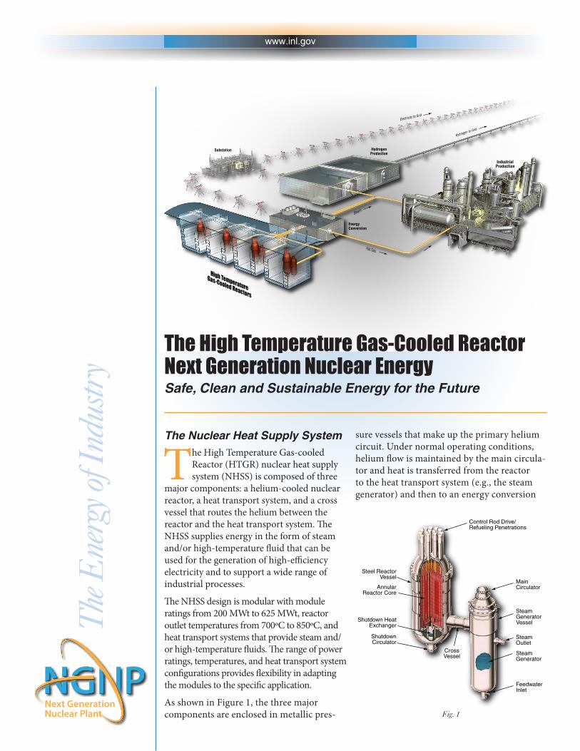
The High Temperature Gas-cooled Reactor (HTGR) nuclear heat supply system (NHSS) is composed of three
major components: a helium-cooled nuclear reactor, a heat transport system, and a cross vessel that routes the helium between the reactor and the heat transport system. The NHSS supplies energy in the form of steam and/or high-temperature fluid that can be used for the generation of high-efficiency electricity and to support a wide range of industrial processes.
The NHSS design is modular with module ratings from 200 MWt to 625 MWt, reactor outlet temperatures from 700ºC to 850ºC, and heat transport systems that provide steam and/or high-temperature fluids. The range of power ratings, temperatures, and heat transport system configurations provides flexibility in adapting the modules to the specific application.
As shown in Figure 1, the three major components are enclosed in metallic pres-
sure vessels that make up the primary helium circuit. Under normal operating conditions, helium flow is maintained by the main circula-tor and heat is transferred from the reactor to the heat transport system (e.g., the steam generator) and then to an energy conversion
Control Rod Drive/Refueling Penetrations
MainCirculator
Steel ReactorVessel
ShutdownCirculator
Shutdown HeatExchanger
AnnularReactor Core
SteamGenerator
FeedwaterInlet
CrossVessel
SteamOutlet
SteamGeneratorVessel
Fig. 1

www.inl.gov
system (e.g., a steam turbine generator) that interfaces with the industrial process and/or the electrical grid. When the reactor and plant are shut down for maintenance or refueling, reactor temperature is maintained by the shutdown cooling system. In the event the heat transport system and shutdown cooling system are not operational (e.g., on loss of all electri-cal power), reactor temperature is maintained via a radial heat transfer path through the reactor pressure vessel to an annular cavity formed between the reactor pressure ves-sel and the reactor building structure, the so-called reactor cavity. The reactor cavity can be actively cooled or cooled by natural circulation. In the event neither of these reactor cavity cooling mechanisms is operational, heat transfer through the reactor building structure to the ground is sufficient to maintain reactor temperatures within acceptable limits.
Achieving the Highest Level of Nuclear SafetyThe principal design objective of the NHSS is to ensure that there is no internal or external event that could lead to substan-tive release of radioactive material from the plant that would require evacuation or sheltering of the public or threaten food and water supplies. This objective is met by provision of:
• Multiplebarrierstothereleaseofradioactivematerialfrom the plant that will not fail under all normal, abnor-mal, and accident conditions whether affected by internal(e.g., loss of all electrical power, a leak in a steam genera-tor tube) or external (e.g., earthquakes, flooding, torna-does) events. These barriers include:
o A robust carbon-based fuel structure that forms theprincipal barrier to release and transport of radioactivematerial. As shown in Figure 2, the fuel is made up ofminute (~1 mm diameter) particles that are composedof multiple ceramic layers surrounding the uranium-based kernels. These ceramic layers are designed toretain the products of nuclear fission and limit releaseto the fuel elements and the helium coolant.
o Distribution and containment of the fuel particles infuel elements (compacts or spheres) of carbon-basedmaterial.
o Enclosure of the fuel elements in a large graphite core.
o Enclosure of the core structure and the helium coolantsystem in ASME Nuclear Grade metallic vessels.
o Enclosure of the NHSS vessels in a robust undergroundreactor building.
Additional reactor characteristics that prevent release of radioactive materials include:
• Extremehigh-temperaturecapabilityoftheceramiccoated and carbon-based fuel and core structure.
• Reactormaterialsincludingthereactorfuelarechemicallycompatible and, in combination, will not react or burn toproduce heat or explosive gases. Helium is inert and thefuel and materials of construction of the reactor core andthe nuclear heat supply system preclude such reactions.
• Plantdesignfeatureslimitintrusionofairorwatersothat the reactor remains shut down and containment ofradioactive materials is maintained.
• Singlephaseandlowheatcapacityminimizesstoredenergy in the helium coolant.
• Inherentnuclearandheattransferpropertiesofthereac-tor design are continuously functional to ensure that thefuel temperatures remain within acceptable limits underall conditions.
• Inherentpropertiesofthereactorcoreregulatenuclearpower so no electrical power, coolant flow or any otheractive systems or operator actions are required to limit
Fig. 2
Pyrolytic CarbonSilicon CarbideUranium Dioxide or Oxycarbide Kernel
Particles CompactsTRISO-coated fuel particles (left) are formed into fuel compacts (center) and inserted into graphite fuel elements (right) for the prismatic reactor
TRISO-coated fuel particles are formedinto fuel spheres for pebble bed reactor
Fuel Element
Prismatic
Pebb
le
HalfSection
5 mm Graphite Layer
Coated Particles Embeddedin Graphite Matrix
Fuel SphereDia 60 mm
Matrix
Fuel-Free ShellFueled Zone
08-50711-01

www.inl.gov
nuclear power levels and fuel temperatures under any condition (Figure 3).
• Reactorsarelocatedundergroundinreinforcedconcretesilos (Figure 4), reducing response to earthquakes andproviding a natural heat transfer path from the core throughthe reactor pressure vessel into the silo and ultimately to thepassive reactor cavity cooling system under loss of all forcedcooling conditions.If the reactor cav-ity cooling systemis unavailable, heattransfer to the ground is sufficient to main-tain fuel temperaturesin the acceptablerange.
• Thegraphitehastheability to absorb largequantities of heat. Ittakes hours or days toreach peak accidenttemperatures (still
well below temperatures that could cause fuel degradation) independent of whether active cooling systems are working or not.
• Theheattransferpathfromthecoretothereactorcavitycooling system and to the ground is continuously functionaland, therefore, available independent of the plant condition.
Spent and Used Fuel Storage• Spentandusedfuelisstoredincasksortanksinunderground
vaults that can be cooled by naturally circulating air (Figure 5).
• Activesystemsarenotrequired to maintainacceptable tempera-tures of stored spentor used (defined asnot completely usedbut removed fromthe core for mainte-nance) fuel due to lowretained energy androbust carbon-basedfuel material.
• Carbon-basedmate-rial used for the fueland fuel elementsfacilitates long-term stable storage.
Clean, Safe Energy with a Wide Range of Applicability:• Anongreenhouse-gas-emittingsourceofenergyforhighly
efficient generation of electricity, steam and high-tempera-ture process heat.
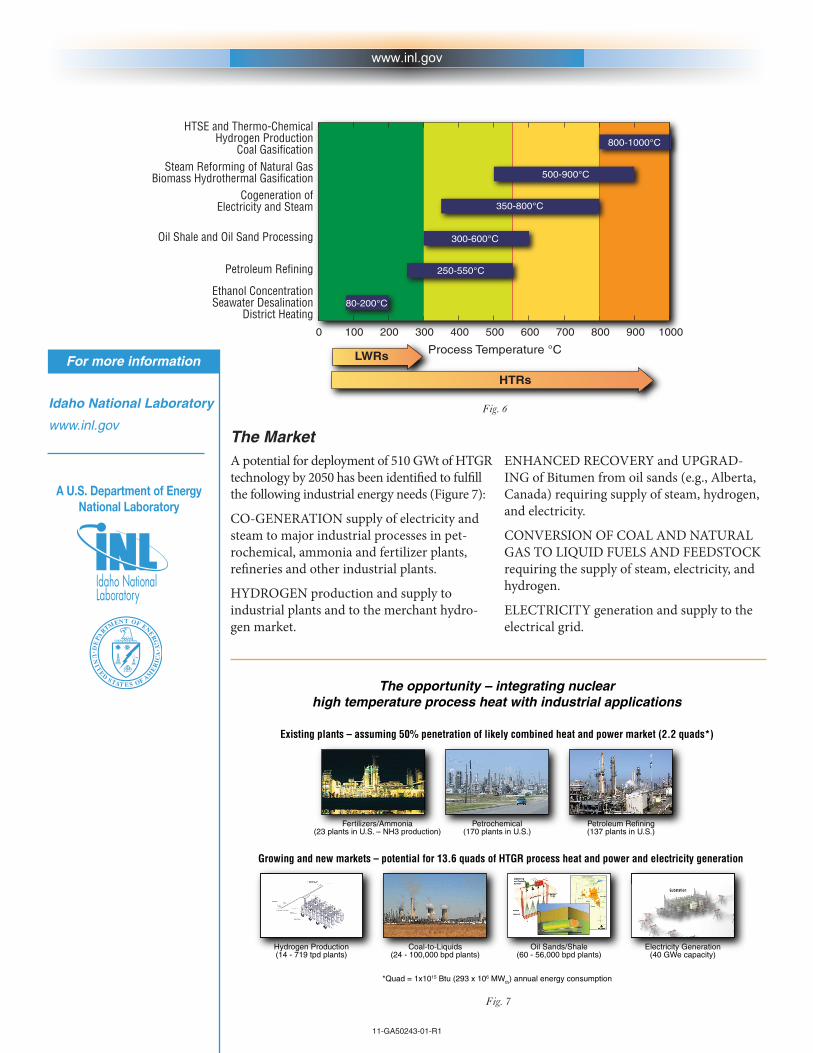
• Anenergysupplythatisapplicabletoawiderangeofhigh-temperature industrial applications beyond production ofelectricity (Figure 6).
• Anenergysupplythatcanbesubstitutedfortheburningof fossil fuels; preserving these natural resources for morebeneficial application (e.g., natural gas feedstock for petro-chemical processing).
• Standardizednuclearheatsupplysystemmodularconfigura-tions with a range of power ratings that provide flexibility inadapting the technology to the application.
• Along-termindigenousenergysupplysystemthatsuppliesenergy at a stable price; eliminating the high volatility inenergy prices experienced over the last several decades.
Fig. 3
B. Boer, D. Lathouwers, J.L. Kloosterman, T.H.J.J. van der Hagen, and G. Strydom, Validation of the DALTON-THERMIX code system with transient analysis of the HTR-10 and application to the PBMR, Nuclear Technology, 170:306-321 (2010)
0 1000 2000 3000 4000 5000 6000 7000−20
−10
0
10
20
30
∆ T
[°C]
t [s]
FuelModRefl
0 1000 2000 3000 4000 5000 6000 70000
0.5
1
1.5
Time [s]
Pow
er [−
]
DALTON−THERMIX
PK−THERMIX
Experiment
A loss of flow test on an experimental reactor (HTR-10) with no control system action – reactor power reduced as a con-sequence of the tempera-ture increase. Calculated differential temperatures are shown for the fuel, moderator, and reflector for first two plus hours after helium flow shutdown. The calculated power response to the temperature varia-tions is shown in compari-son with the test data.
Roof
Grade
Fuel HandlingFloor
Fuel HandlingEquipment
SteamGenerator
Vessel
RCCS InletExhaust Structure
El (-) 28-0”
El (-) 144-0”
Reactor Vessel
OperatingFloor El 0’-5”
Fig. 4
Fig. 5
Fresh Fuel Canisters
PassiveCooling Ducts
Spent FuelTanks
Fuel LiftingLines
Valve Blocks
www.inl.gov
The MarketA potential for deployment of 510 GWt of HTGR technology by 2050 has been identified to fulfill the following industrial energy needs (Figure 7):
CO-GENERATION supply of electricity and steam to major industrial processes in pet-rochemical,ammoniaandfertilizerplants,refineries and other industrial plants.
HYDROGEN production and supply to industrial plants and to the merchant hydro-gen market.
11-GA50243-01-R1
Idaho National Laboratory
www.inl.gov
For more information
A U.S. Department of EnergyNational Laboratory
ENHANCEDRECOVERYandUPGRAD-ING of Bitumen from oil sands (e.g., Alberta, Canada) requiring supply of steam, hydrogen, and electricity.
CONVERSION OF COAL AND NATURAL GAS TO LIQUID FUELS AND FEEDSTOCK requiring the supply of steam, electricity, and hydrogen.
ELECTRICITY generation and supply to the electrical grid.
Fig. 7
HTSE and Thermo-ChemicalHydrogen Production
Coal GasificationSteam Reforming of Natural Gas
Biomass Hydrothermal GasificationCogeneration of
Electricity and Steam
Oil Shale and Oil Sand Processing
Petroleum Refining
Ethanol ConcentrationSeawater Desalination
District Heating0 100 200 300 400 500
Process Temperature °C
600 700 800 900 1000
LWRs
HTRs
800-1000°C
500-900°C
350-800°C
300-600°C
250-550°C
80-200°C
Fig. 6
The opportunity – integrating nuclearhigh temperature process heat with industrial applications
Existing plants – assuming 50% penetration of likely combined heat and power market (2.2 quads*)
Growing and new markets – potential for 13.6 quads of HTGR process heat and power and electricity generation
*Quad = 1x10¹⁵ Btu (293 x 106 MWth) annual energy consumption
Petroleum Refining(137 plants in U.S.)
Electricity Generation(40 GWe capacity)
Hydrogen Production(14 - 719 tpd plants)
Coal-to-Liquids(24 - 100,000 bpd plants)
Fertilizers/Ammonia(23 plants in U.S. – NH3 production)
Petrochemical(170 plants in U.S.)
Oil Sands/Shale(60 - 56,000 bpd plants)