The HDS series pump is a heavy duty pump that is designed to …totalpumpgroup.com/Products/TPG-HDS...
5
HDS Centrifugal Slurry pumps We’re with you every step of the way The HDS series pump is a heavy duty pump that is designed to handle the most abrasive and dense slurries. The HDS series pump offers users a wide range of seal and liner configurations, allowing the pump to be fully customised to meet our customer’s specific application requirements. HDS series pump design features 52 years of pump manufacturing and design experience – In addition to this wealth of experience, we have used the latest and most advanced computer aided engineering software, to ensure that we offer our customers the best performance, longevity and reliability under the toughest conditions. Discharge outlet – The discharge outlet of the HDS series pump has eight (8) positions at 45 degree intervals that can be selected to best meet application and installation requirements. Bearing assemblies – The large diameter shaft uses a unique oil bathed cylindrical bearing to ensure unsurpassed service life and reliability. Only four bolts are required to hold the housing frame in place, further enhancing serviceability and maximising uptime. Oil bathed cylindrical bearings
Transcript of The HDS series pump is a heavy duty pump that is designed to …totalpumpgroup.com/Products/TPG-HDS...

HDS Centrifugal Slurry pumps We’re with you every step of the way
The HDS series pump is a heavy duty pump that is designed to handle the most abrasive and dense
slurries. The HDS series pump offers users a wide range of seal and liner configurations, allowing
the pump to be fully customised to meet our customer’s specific application requirements.
HDS series pump design features
52 years of pump manufacturing and design
experience – In addition to this wealth of
experience, we have used the latest and most
advanced computer aided engineering
software, to ensure that we offer our
customers the best performance, longevity and
reliability under the toughest conditions.
Discharge outlet – The discharge outlet of the
HDS series pump has eight (8) positions at 45
degree intervals that can be selected to best
meet application and installation requirements.
Bearing assemblies – The large diameter shaft
uses a unique oil bathed cylindrical bearing to
ensure unsurpassed service life and reliability.
Only four bolts are required to hold the
housing frame in place, further enhancing
serviceability and maximising uptime.
Oil bathed cylindrical bearings
Additional protection to reduce maintenance and
increase component life
Seals - The HDS series pump provides
customers with a variety of seal options to
meet a broad range of operating conditions
and customer specific requirements. Please
see the following illustrations for some of the
sealing options that are available;
Expeller Dynamic Seal
Packing Seal This sealing system is suitable for a wide range of applications and can be used in high corrosion and high temperature applications. Seals can be made of polytetrafluoroethylene, graphite and other materials depending on the application. For high abrasion conditions, a ceramic shaft sleave is available.
Packing Seal Arrangement
Mechanical Seal
HDS series pumps utilises a world-leading leak-
proof mechanical seal design, that allows for
easy installation and replacement. This seal
configuration is suitable for the toughest
conditions. We utilise special ceramic and
alloys of high strength and hardness on parts
that are subjected to heavy friction. Amongst
the many characteristics of this seal design, is
its excellent resistance to abrasivity and shock
that ensures its effectiveness under the
toughest conditions.
GRJ Mechanical Seal
HRJ Mechanical Seal
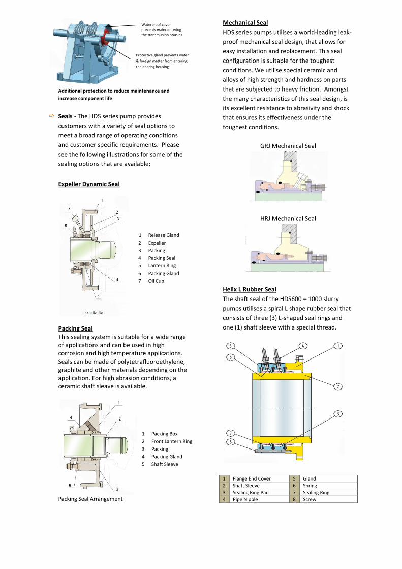
Helix L Rubber Seal
The shaft seal of the HDS600 – 1000 slurry
pumps utilises a spiral L shape rubber seal that
consists of three (3) L-shaped seal rings and
one (1) shaft sleeve with a special thread.
1 Flange End Cover 5 Gland
2 Shaft Sleeve 6 Spring
3 Sealing Ring Pad 7 Sealing Ring
4 Pipe Nipple 8 Screw
Waterproof cover prevents water entering the transmission housing
Protective gland prevents water
& foreign matter from entering
the bearing housing
1 Release Gland
2 Expeller
3 Packing
4 Packing Seal
5 Lantern Ring
6 Packing Gland
7 Oil Cup
1 Packing Box
2 Front Lantern Ring
3 Packing
4 Packing Gland
5 Shaft Sleeve

Material Research
Centrifugal slurry pumps are widely used to transport solids and liquids across many industries such
as metalliferous mining, coal mining, electric power plants, the chemical Industry, the food Industry ,
sewage treatment plants, and channel dredging to name a few. Slurry pumps play a vital role in all of
their applications and must efficiently and economically satisfy the production, serviceability and
durability requirements of both the customer and the application. Due to the broad and stringent
requirements for quality and performance, we have spent considerable time and effort in researching
and testing materials and improved pump designs to ensure that our pumps and components offer
the best service life possible. The Series K range of materials can be adapted to meet any type of
application and specific wear requirements. Series K materials include anti-corrosive, anti-wear,
alloys, metals and non metallic items. Only the best and most suitable materials have been
incorporated into the design of the HDS series pumps. We are fully committed to providing quality
products that are easy to service and maintain and that offer excellent performance and durability
under all conditions.
General Mechanical Properties
TYPE MATERIAL
CODE MATERIAL
BRAND
MECHANICAL PROPERTIES PERFORMANCE APPLICATION δ w/ δ b
(MPa) a k
(j/cm2) HRC
Anti-wear White Iron
KB04 KmTBCCr26 ≥700 6-7 ≥56
Erosion resistance is marginally lower than KB06 and has corrosion resistance
Used for high wear applications with a pH between 5 and 12
KB06 KmTBCr15Mo ≥550 4-8 ≥59
Best erosion resistance but has lower wear resistance than KB03 &KB04
Used for high wear applications
KB01 KmTBCCr8 ≥550 6-8 ≥55 Erosion resistance is 0.9 times that of KB04
Used for mud pumps
KB07 KmTBMnMo ≥400 3-6 38-42
Mild erosion resistance and lower hardness. This material can be drilled and tapped
Used for mid wear applications with fine grain medium
Anti-wear and Anti-corrosive
iron
KB09 ≥600 43
This material has erosive and corrosive resistance in low pH applications. Its wear resistance is similar to KB02
Used for low pH applications of less than 4. This material is particularly suitable for flue gas desulphurisation (FGD) and other mild acidic applications
KB33 45
This material has similar erosion resistance to KB02 and also has good corrosion resistance
This material can be used to transport oxygenated slurries with pH of not less than 1 such as phosphor-plaster, nitric acid, vitriol, phosphate etc
Anti-wear Cast Steel
KM03 ≥1200 HB
350-500
This material has is of high harness and has good anti-erosion properties
Used in high wear, high erosion and high corrosion applications
KM05 ≥1000 HB
≥350
Mild harness material with anti-wear and anti-corrosion resistance. This material is weldable
Used for mild erosion wear applications such transporting water medium with fine granular particles

HDS Slurry Pump Selection Guide (discharge diameter ≤450mm)
Type
Max
Available
Matching
Power
(kW)
Material Performance under Clear Water Impeller
Liner Impeller
Flow Capacity (Q) Head
(m)
Rotational
Speed
(r/min)
Max
Efficiency
(%)
NPSH
(m)
No.
Diameter
(mm) m3/h l/s
20HDS-B 15
M M 12.6-28.8 3.5-8 6-68 1200-3800 40
2-4
5
152
R R 10.8-25.2 3-7 7-52 1400-3400 35 3
20HDSH-C 30 M M 16.2-34.2 4.5-9.5 25-92 1400-2200 20 2-5.5 5 330
40HDS-B 15
M M 32.4-72 9-20 6-58 1200-3200 45 3.5-8
5
184
R R 25.2-54 7-15 5.5-41 1000-2600 50 2.5-5 178
50HDS-C 30
M M 39.6-86.4 11-24 12-64 1300-2700 55 4-6
5
214
R R 36-75.6 10-21 13-46 1300-2300 60 2-4 213
50HDSH-D 60 M M 68.4-136.8 19-38 25-87 850-1400 47 3-7.5 5 457
75HDS-C 30
M M 86.4-198 24-55 9-52 1000-2200 71 4-6
5 245
R R 79.2-180 22-50 5-34.5 800-1800 59 3-5
75HDSH-E 120 M M 126-252 35-70 12-97 600-1400 50 2-5 5 508
100HDS-D 60
M M 162-360 40-100 12-56 800-1550 65 5-8
5
365
R R 144-324 40-90 12-45 800-1350 65 3-5 365
100HDS-F 560 M M 324-720 90-200 30-118 600-1000 64 3-8 5 711
150HDS-E 560 M M 468-1008 130-280 20-94 500-1000 65 4-12 5 711
R150HDS-E 300
M M 360-828 100-230 10-61 500-1140 72 2-9
5
510
R R 324-720 90-200 7-49 400-1000 65 5-10 510
200HDS-E 120 M M 666-1440 185-400 14-60 600-1100 73 4-10 5 549
200HDS-ST 560
M M 612-1368 170-380 11-61 400-850 71 4-10
5 686
R R 540-1188 150-330 12-50 400-750 75 4-12
250HDS-ST 560
M M 936-1980 260-550 7-68 300-800 82 6
5 762
R R 720-1620 200-450 7-45 300-650 80 2.5-7.5
300HDS-ST 560
M M 1260-2772 350-770 13-63 300-600 77 3-10
5 965
R R 1152-2520 320-700 13-44 300-500 79 3-8
350HDS-TU 1200 M M 1368-3060 380-850 11-63 250-550 79 4-10 5 1067
450HDS-TU 1200 M M 2520-5400 700-1500 13-57 200-400 85 5-10 5 1370
Note 1. “R” = rubber “M” = wear resistant alloys
2. Recommended capacity range: 50% Q ≤ Q ≤ 110% Q (Q represents capacity at the highest efficiency point)
3. NPHS corresponds to point Q at the highest recommended speed

Slurry Pump Selection Guide (discharge diameter ≥ 600mm)
TYPE CAPACITY (m3
/h) HEAD (m) SPEED (r/m)
EFFICIENCY (%)
NPSHr (m)
MAX DIAMETER OF
FLOW THROUGH PARTICLES
(mm)
WEIGHT (kg)
M600HDS-A 6500 - 7500 30 - 65 350 - 480 80 ≤6 220 3000
M700HDS-A 8000 - 10000 30 - 70 250 - 400 85 ≤6 280 4500
M800HDS-A 10000 - 13000 30 - 65 250 – 360 81 ≤6 300 4000
M850HDS-A 13000 - 15000 30 - 75 250 - 340 85 ≤6 320 6500
M900HDS-A 13000 - 18000 22 - 78 175 - 290 85 ≤6 340 8000
M1000HDS-A 18000 - 25000 23 -76 180 - 290 85 - 87 ≤6 350 12100
Pump Installation dimensions
TYPE A B C D U E F G H J K L M N V T S n-d
20HDS-B 585 295 248 197 28 79 206 187 98 171 46 - 140 255 191 38 24 4-ф14
40HDS-B 595 295 248 197 28 79 217 205 114 184 30 - 140 255 194 38 24 4-ф14
50HDS-C 770 406 311 255 42 125 280 238 138 210 58 - 170 355 234 48 35.5 4-ф19
75HDS-C 845 406 311 255 42 125 354 292 149 262 15 - 170 355 271 48 35.5 4-ф19
100HDS-E 1180 622 448 457 80 222 433 406 229 338 117 - 260 545 351 76 54 4-ф29
150HDS-F 1510 857 635 610 100 280 539 551 318 460 93 - 350 760 438 98 95 4-ф35
200HDS-S 1745 1150 780 650 120 280 692 677 419 635 28 - 620 900 439 125 80 4-ф48
250HDS-S 1840 1150 780 650 120 280 762 755 464 673 - 85 620 900 461 125 80 4-ф48
300HDS-T 2270 1150 1040 650 150 352 813 944 629 832 - 191 880 900 486 120 80 4-ф48
350HDS-U 2320 1460 1050 900 150 351 953 1075 940 889 - 115 860 1200 597 150 95 4-ф79
450HDS-U 2535 1444 1050 900 150 351 1100 1444 940 1230 - 47 860 1200 615 150 95 4-ф79
Note: for pumps with a discharge diameter greater than ≥600mm the installation dimensions and drawing are to be provided by the
customer.
14 Raine Street Woollahra NSW 2025, AUSTRALIA Mobile: +61 404 089 827 Fax: +61 2 9327 8563 Email: [email protected] Web: www.totalpumpgroup.com
We’re with you every step of the way